effect of high magnetic field on organic light emitting diodes
TRANSCRIPT

12
Effect of High Magnetic Field on Organic Light Emitting Diodes
Toshihiro Shimada Hokkaido University
Japan
1. Introduction
This chapter aims at reviewing magnetic field effects (MFE) in organic light emitting diodes (OLED) with an emphasis on our study under high magnetic field up to 9 T. This subject includes organic spintronics in general, which is a hot subject attracting many researchers recently. Since singlet-triplet conversion in excitons is critically important in the current efficiency of OLEDs, spintronics aspects of OLEDs should be studied in detail. However, due to the difficulty in the fabrication of stable devices, the number of the researches has been limited. We have found two things up to now, by making very stable OLEDs and measuring them under high magnetic fields. (1) Efficiency of OLEDs decreases quadrically with the magnetic field up to 6 T and the rate of decrease becomes smaller between 6T and 9T. (2) Minority carrier conductivity decreases linearly with the magnetic field, whereas that of majority carrier is almost constant. (3) Anomalous behaviors (large magnetoresistance etc.) are only seen in bipolar injection, which agrees with previous reports. Although the mechanisms behind these findings have not been clarified yet, some hypotheses have been made with the analogy with MFE on chemical reactions. In principle, MFE on charge transport and recombination has similarity with chemical reaction under magnetic field, and the terminology and concept should be parallel between these subjects. We will try to combine the current knowledge of organic charge transport, OLEDs, spintronics and MFEs of chemical reaction to make a unified picture of these issues.
2. Spins in organic devices
2.1 Spins in OLEDs The roles of spins in OLEDs and other organic devices are discussed well but have not been clarified quantitatively in experiments. We will review it in terms of OLED efficiency first. Figure 1 shows the schematic mechanism of OLED with the emphasis on the spin states. Since most of the organic semiconductors are used as intrinsic, the charges are transported via HOMO (highest occupied molecular orbital, in the case of holes) or LUMO (lowest unoccupied molecular orbital, in the case of electrons) of organic semiconductor molecules, usually by hopping in amorphous devices. Electrons and holes finally meet in one luminescent molecule and make excited states or excitons. The important thing is that there are two kinds of excitons, namely singlet excitons and triplet excitons. Although singlet
www.intechopen.com

Organic Light Emitting Diode – Material, Process and Devices
312
excitons can be relaxed radiatively, triplet excitons cannot emit light in ordinary materials due to the spin selection rule. Since the charges injected from electrodes are not spin polarized unless spintronics techniques were used, the spin polarizaion statistics is singlet : triplet = 1 : 3. The emission efficiency of OLEDs are governed by this factor and it is well known that incorporation of heavy atoms (Pt, Ir etc.) in the luminescent dye molecule greatly alleviate this burden via intersystem crossing (Baldo et al. 1999). Since the chemical synthesis of the luminescent molecules with heavy atoms is not fully developed and the heavy atoms are costly, other methods such as applying magnetic field to OLED (Kalinowski 1997) or mixing magnetic nanoparticles in the device (Hu et al. 2006, Sun et al. 2007) have been attempted. These approaches uses MFEs on carrier injection, transport and recombination, which are related with spintronics of organic semiconductors. Pure MFE without using magnetic electrodes has been studied. Experimentally, the reports on MFE of OLEDs without ferromagnetic component qualitatively agree with each other, i.e., steep increase in efficiency (2~10%) in the low magnetic field (< 100mT) and gradual decrease in the higher magnetic field. Although the behavior in the low magnetic field region is intensively studied and complicated phenomena including magnetoresistance are being elucidated (Bobbert et al., 2007; Davis & Bussmann, 2004; Desai et al., 2007a, 2007b; Hu & Wu, 2007; Kalinowski, 1997; Kalinowski et al., 2003, 2004; Lei et al., 2009; Liu et al., 2009; Odaka et al., 2006; Sakaguchi et al., 2006; Shakya et al., 2008; Shemg et al. 2007), very few experiments in relation to the MFE on organic semiconductors have been performed under high magnetic field larger than 2T (Reufer et al. 2005).
Fig. 1. Role of spins in organic light emitting diodes (OLEDs).
2.2 Organic spintronics Spintronics study is now extended to all kinds of semiconductor materials. Organic semiconductors are not the exception. Since organic semiconductors consist of light elements such as carbon, hydrogen, oxygen and nitrogen, lifetime of spin polarized carriers might be long in organic semiconductors. After the proposal of this concept (Dediu et al. 2002), many papers have been published on the spin injection and transport in organic semiconductors. Most of the researches have been focused on performance of spin valves and magnetoresistance of organic semiconductors. A spin valve is a two terminal device consisting
www.intechopen.com
Effect of High Magnetic Field on Organic Light Emitting Diodes
313
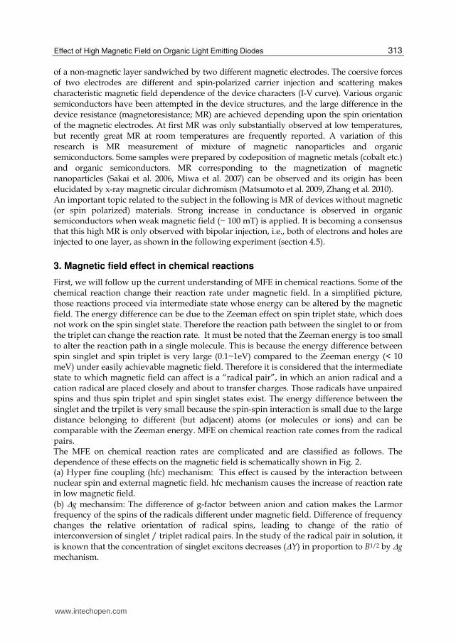
of a non-magnetic layer sandwiched by two different magnetic electrodes. The coersive forces of two electrodes are different and spin-polarized carrier injection and scattering makes characteristic magnetic field dependence of the device characters (I-V curve). Various organic semiconductors have been attempted in the device structures, and the large difference in the device resistance (magnetoresistance; MR) are achieved depending upon the spin orientation of the magnetic electrodes. At first MR was only substantially observed at low temperatures, but recently great MR at room temperatures are frequently reported. A variation of this research is MR measurement of mixture of magnetic nanoparticles and organic semiconductors. Some samples were prepared by codeposition of magnetic metals (cobalt etc.) and organic semiconductors. MR corresponding to the magnetization of magnetic nanoparticles (Sakai et al. 2006, Miwa et al. 2007) can be observed and its origin has been elucidated by x-ray magnetic circular dichromism (Matsumoto et al. 2009, Zhang et al. 2010). An important topic related to the subject in the following is MR of devices without magnetic (or spin polarized) materials. Strong increase in conductance is observed in organic semiconductors when weak magnetic field (~ 100 mT) is applied. It is becoming a consensus that this high MR is only observed with bipolar injection, i.e., both of electrons and holes are injected to one layer, as shown in the following experiment (section 4.5).
3. Magnetic field effect in chemical reactions
First, we will follow up the current understanding of MFE in chemical reactions. Some of the chemical reaction change their reaction rate under magnetic field. In a simplified picture, those reactions proceed via intermediate state whose energy can be altered by the magnetic field. The energy difference can be due to the Zeeman effect on spin triplet state, which does not work on the spin singlet state. Therefore the reaction path between the singlet to or from the triplet can change the reaction rate. It must be noted that the Zeeman energy is too small to alter the reaction path in a single molecule. This is because the energy difference between spin singlet and spin triplet is very large (0.1~1eV) compared to the Zeeman energy (< 10 meV) under easily achievable magnetic field. Therefore it is considered that the intermediate state to which magnetic field can affect is a “radical pair”, in which an anion radical and a cation radical are placed closely and about to transfer charges. Those radicals have unpaired spins and thus spin triplet and spin singlet states exist. The energy difference between the singlet and the trpilet is very small because the spin-spin interaction is small due to the large distance belonging to different (but adjacent) atoms (or molecules or ions) and can be comparable with the Zeeman energy. MFE on chemical reaction rate comes from the radical pairs. The MFE on chemical reaction rates are complicated and are classified as follows. The dependence of these effects on the magnetic field is schematically shown in Fig. 2. (a) Hyper fine coupling (hfc) mechanism: This effect is caused by the interaction between nuclear spin and external magnetic field. hfc mechanism causes the increase of reaction rate in low magnetic field.
(b) g mechansim: The difference of g-factor between anion and cation makes the Larmor frequency of the spins of the radicals different under magnetic field. Difference of frequency changes the relative orientation of radical spins, leading to change of the ratio of interconversion of singlet / triplet radical pairs. In the study of the radical pair in solution, it
is known that the concentration of singlet excitons decreases (Y) in proportion to B1/2 by g mechanism.
www.intechopen.com
Organic Light Emitting Diode – Material, Process and Devices
314
1/2
2Bg Bm
Yp
, (1)
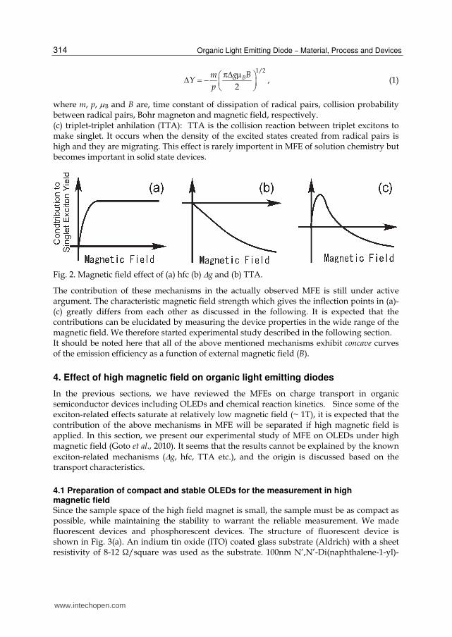
where m, p, B and B are, time constant of dissipation of radical pairs, collision probability between radical pairs, Bohr magneton and magnetic field, respectively. (c) triplet-triplet anhilation (TTA): TTA is the collision reaction between triplet excitons to make singlet. It occurs when the density of the excited states created from radical pairs is high and they are migrating. This effect is rarely importent in MFE of solution chemistry but becomes important in solid state devices.
Fig. 2. Magnetic field effect of (a) hfc (b) g and (b) TTA.
The contribution of these mechanisms in the actually observed MFE is still under active argument. The characteristic magnetic field strength which gives the inflection points in (a)-(c) greatly differs from each other as discussed in the following. It is expected that the contributions can be elucidated by measuring the device properties in the wide range of the magnetic field. We therefore started experimental study described in the following section. It should be noted here that all of the above mentioned mechanisms exhibit concave curves of the emission efficiency as a function of external magnetic field (B).
4. Effect of high magnetic field on organic light emitting diodes
In the previous sections, we have reviewed the MFEs on charge transport in organic semiconductor devices including OLEDs and chemical reaction kinetics. Since some of the exciton-related effects saturate at relatively low magnetic field (~ 1T), it is expected that the contribution of the above mechanisms in MFE will be separated if high magnetic field is applied. In this section, we present our experimental study of MFE on OLEDs under high magnetic field (Goto et al., 2010). It seems that the results cannot be explained by the known
exciton-related mechanisms (g, hfc, TTA etc.), and the origin is discussed based on the transport characteristics.
4.1 Preparation of compact and stable OLEDs for the measurement in high magnetic field Since the sample space of the high field magnet is small, the sample must be as compact as possible, while maintaining the stability to warrant the reliable measurement. We made fluorescent devices and phosphorescent devices. The structure of fluorescent device is shown in Fig. 3(a). An indium tin oxide (ITO) coated glass substrate (Aldrich) with a sheet resistivity of 8-12 Ω/square was used as the substrate. 100nm N’,N’-Di(naphthalene-1-yl)-
www.intechopen.com

Effect of High Magnetic Field on Organic Light Emitting Diodes
315
N,N’ dipheyl-benzidine (-NPD) and 100nm Tris-(8-hydroxyquinolino) aluminum (Alq) were deposited successively as the hole transporting layer and emitting & electron transporting layer, respectively. Then a cathode was deposited, which consisted of a 2 nm Cs layer followed by 150 nm of Al. The ITO substrate was cleaned by ultrasonicating in ethanol and acetone. Following this, the ITO was treated in ozone for 20 min.. The
deposition of the organic layers (-NPD and Alq, Luminescence Technology Corporation) was performed using Knudsen-cells in a vacuum chamber with a base pressure during evaporation of ~10-7 Torr. Cs was deposited with alkali metal dispenser (SAES Getters). The deposition rate of organic materials was about 0.1 nm / s, which was measured by calibrated quartz crystal microbalances. The structure of phosphorescence device is shown in Fig. 3(b). Doping of 5% Btp2Ir(acac) in CBP was performed by controlling the evaporation rate by monitoring the quartz crystal microbalances. The sample OLEDs and unipolar devices were transferred from the deposition chamber to glove box filled with dry N2 without exposing them to air. The electrical connection to the OLED was made using thin Cu wire with In contact. Then the OLED sample was sealed in a glass box (made of O.D. 20 mm x t 3 mm pyrex tube and two t 0.1mm glass plates) using photo-hardening epoxy (Threebond 3124) together with a zeolite desiccant (Shinagawa Kasei Co. LTD). These sealing process was essential to obtain stable devices.
Fig. 3. Structure of (a) fluorescence and (b) phosphorescence devices
4.2 Measurement under magnetic field MFE was measured at 300K in superconducting magnet using Physical Property Measurement System (PPMS; Quantum Design). The magnetic field was perpendicular to the device plane. The magnetic field was increased from 0 T to 9 T and then was decreased from 9 T to 0 T in order to check the temporal changes. The results are shown after confirming pure MFE is observed, unless stated otherwise. The emission intensity was measured with photon counter H7155-21 (Hamamatsu) in magnetic shielding made of thick iron plates and cylinders. The shielding of photon counter was tested and it was confirmed that there was no magnetic field dependence on its output. The bias was applied by the Keithley 6487 picoammeter / voltage source in constant voltage mode.
www.intechopen.com

Organic Light Emitting Diode – Material, Process and Devices
316
4.3 Results of fluorescent OLED First we show the characteristics of the fluorescent device without applying the magnetic field. Figure 4(a) shows the emission intensity and current of the fluorescent OLED as a function of voltage, together with those of a phosphorescent device (Fig.4(b)). It is reported that TTA in Alq-based fluorescent OLEDs occurs when the current density is larger than 100 mA/cm2
(Kondakov 2007) and some of our measurement exceeds this limit. However, since the magnetic field dependence of TTA appears only at low temperatures (Lei et al. 2009, Liu et al. 2009), we consider we can neglect contribution from TTA in the present measurement at 300 K.
Fig. 4. I-V and light emitting properties of (a) fluorescent and (b) phosphorescent devices without magnetic field.
The emission intensity, current and emission efficiency of the same device under the magnetic field are shown in Fig. 5. The emission intensity and current show different magnetic field dependence on the sweep direction (0 -> 9T / 9 -> 0T) (Fig 5 (a)(b)). However, their ratio, i.e. emission efficiency, does not show the hysteresis as shown in Fig. 5(c). It means that the hysteresis comes from the charge injection process from the electrodes to the emission layer. We found that the "hysteresis" is dependent on both of the magnetic field and the time from the start of the current flow. The time dependence is probably due to the bias stress on the device, but the magnetic field dependence might be related with MFE of the trap / detrap processes.
Fig. 5. Magnetic field effect of the fluorescent device (normalized at zero field). ((a) Emission Intensity, (b) Current, (c) Emission Efficiency at 4V). The arrows show the sweep direction.
The emission efficiency (and also the emission intensity and the current) increase steeply as a function of B when it was less than 0.02 T as reported in the literature, and gradually
www.intechopen.com

Effect of High Magnetic Field on Organic Light Emitting Diodes
317
decreases as B was further increased. It should be noted that the decrease in the mid~ high B
region is convex function, which cannot be explained by widely accepted behavior of hfc, g and TTA mechanisms which exhibit concave behavior against B. We will discuss this point later. In order to see dependence on B more clearly, we re-plotted Fig. 5(c) as a function of B2. Figure 6(a) clearly shows the linear decrease of the fluorescent efficiency against B2 in the range of 0.1 T~ 6.5 T. On the other hand, by re-plotting Fig 5(c) as a function of B1/2 (Fig. 6(b)), it is noticed that the decrease of the emission efficiency shows B1/2 dependence in the range of 6.5 T ~ 9 T.
Fig. 6. Normalized emission efficiency of the fluorescent device plotted as a function of (a) B2 (b) B1/2.
4.4 Results on phosphorescent OLED Figure 7 shows the MFE on the emission efficiency of the phosphorescent OLED. In contrast to the results of the fluorescent device, it did not show the magnetic field dependence. Although we changed the driving voltage (4V, 6V, 8V, 10V), the magnetic field dependence did not appear.
Fig. 7. Magnetic field effect of the phosphorescent device (normalized at zero field). The result at 10V is shown.
www.intechopen.com

Organic Light Emitting Diode – Material, Process and Devices
318
4.5 Magnetoconductance measurement of unipolar devices In order to investigate the charge balance factor which might influence the EL efficiency, we
measured the magnetoresistance of the majority and minority carriers in -NPD and Alq by making the unijunction devices with different work function electrodes (Au and Cs). All of the devices showed Ohmic I -V characteristics in the measured range (-10~10V). The results of MFE on the current at constant voltage are shown in Figs. 8(a)-(d). The voltages were
chosen to give current in the range of 10~100 A and the results are shown after normalization at zero field. It is easily noticed that the MFEs on the conductivity of the
majority carriers (holes in -NPD and electrons in Alq) are negligible, whereas linear
decreases in the conductivity was observed for the minority carriers (electrons in -NPD and holes in Alq). Since the I-V characteristics are Ohmic, it shows the carrier mobility values of the minority carriers decrease linearly as a function of the magnetic field.
Fig. 8. Magnetic field effect of conductance of unipolar devices (normalized at zero field).
(a)Au/-NPD/Au (holes) (b)Au/Cs/-NPD/Cs/Au (electrons) (c)Au/Cs/Alq/Cs/Au (electrons) (d)Au/Alq/Au (holes)
Also it should be noted that steep increase around zero field was not observed in unipolar devices, which agrees with previous reports (Yusoff, 2009).
4.6 Discussions – the origin of field dependence We found the decrease in the fluorescent efficiency in organic EL devices proportional to B2 in the range of 0.1~6.5T. Such dependence has not been reported to the authors' knowledge.
The EL efficiency ( ext ) is given by the following:
ext = PL exciton (2)
Here, , PL, exciton, are the light extraction efficiency, quantum efficiency of organic material, exciton formation efficiency, and carrier balance factor, respectively. is related with the magnetic field via Faraday /Kerr effects with interference. The Faraday rotation of the non-magnetic and thin organic layers is not significant even at 9T and
interference would not change as a function of magnetic field. Thus we can neglect . The fluorescent in optically excited organic dyes in the magnetic field has been studied in detail (Katoh & Kotani 1992), but B2 dependence in high magnetic field was not reported in the
literature. Therefore, our result cannot be explained by PL. Since all known mechanism of
www.intechopen.com

Effect of High Magnetic Field on Organic Light Emitting Diodes
319
MFE on exciton gives concave dependence on B as mentioned earlier, we here tentatively
rule out the contribution from exciton as the main mechanism of the present B2 dependence. The remaining factor in eq. (2) is the charge balance factor. We examined various models to
relate the MFE on the charge balance factor, and the following is the only model that can
barely explain the B2 dependence. We observed that the conductance of the minority carrier
changes linearly as a function of magnetic field as shown in Fig. 8. We considered various
models based on our observation that the mobility of the minority carrier () depends upon
the magnetic field (B) as
= 0 (1 - aB) (3)
where 0 and a are materials dependent constants. Since the EL intensity is determined
only by the charge balance if the carrier recombination rate is proportional to the
radiation (Scott et al. 1997), eq. (3) gives the fluorescent efficiency linearly related with B1.
However, our experiments showed that the current remains almost constant as a function
of the magnetic field in the mid ~ high B range. We have found that we can deduce the B2
dependence from eq. (3) with additional two assumptions. The assumptions are as
follows. (i) The emission region is very narrow and only the recombination at this region
contributes to the emission. This is reasonable because Alq layer (200nm) is much thicker
than the thickness of emission region of ordinary devices. The interfacial mixing and the
damage caused by the electrode formation might also justify this assumption. (ii) The hole
current (Jh) and electron current (Je) are balanced in the emission region when B = 0. Since
the mobility of the majority carrier is smaller in Alq than -NPD (Kepler et al. 1995,
Nguyen et al. 2007), it is believed that the recombination and the emission occurs in Alq.
This assumption is also reasonable because the device characteristics (Fig. 4), in which
turn-on voltage of current is almost the same as that of emission intensity, show that this
device has good carrier balance.
Since the current is constant as a function of B, Jh + Je is constant. From the assumption (ii), Jh
= Je at the emission region when B=0. The emission region is in Alq and Eq.(3) becomes
Jh = J0(1-aB), (4)
where J0 is a constant. Because Jh+Je is constant, Je at the emission region can be written as
Je=J0(1+aB). (5)
The recombination rate is proportional to JhJe
JhJe = J02 (1-aB)(1+aB) = J02 (1-a2B2) (6)
and the decrease of the emission proportional to B2 is explained. We understand that the carrier transport of unipolar devices are not the same as the bipolar
devices, for example, charge injection at the electrodes might be strongly involved in the
minority carriers. However, our finding of linear MFE on minority carriers has not been
reported and no theoretical prediction has been made to the author's knowledge. There
might exist other mechanisms which also explain these results, but we hope the present
result and discussions may stimulate the study of MFE on organic semiconductors and
devices. Although TTA is not likely to work at room temperature and hfc will saturate at
www.intechopen.com

Organic Light Emitting Diode – Material, Process and Devices
320
relatively low magnetic field, G works at high magnetic field region and might be
cooperative with other factors.
There is another mechanism which might explain the B2 dependence, although it is not consistent with the results on the unipolar devices (eq.(3)). It is theoretically predicted that the decrease of the conductivity proportional to B2 is characteristics of magnetoresistance of hopping transport and that it levels off to the B1 dependence when the magnetic field is high (Kepler et al. 1995). If it is applicable to the carriers in the emission layer of an OLED, the charge balance of the device will change in the same manner as the conductance and the emission decrease proportional to B2 will be observed. The difficulty of this model is that we did not see such magnetoconductance in unipolar devices with organic single layers. In the range beyond 6.5T, we observed B1/2 dependence (Fig. 6(b)). In the study of the radical pair in solution, it is known that the density of singlet excitons decreases in
proportion to B1/2 by g mechanism (Sakaguchi & Hayashi 1995). The magnetoconductance of the minority carriers shown in Fig. 8 start to saturate in the range beyond 6.5 T. It might
be the reason why B1/2 dependence due to g mechanism start to appear in this region. We did not find observable MFE in phosphorescent OLEDs (Fig.7). This result indicates that intersystem crossing occurs so fast in RPs and excited state molecules that Larmor precession
in g mechanism does not affect the recombination kinetics. It also suggest that the charge balance effect discussed above does not come into play. It will be interesting to measure the magnetoconductance of organic semiconductors doped with phosphorescent dyes.
5. Conclusion
We reviewed recent studies on organic spintronics and MFE on chemical reactions in relation to the MFE on OLEDs. We measured EL efficiency of fluorescent and phosphorescent OLEDs in the magnetic field up to 9T and in the fluorescent device we found quadratic decrease as a function of the magnetic field between 0.1 ~ 6.5T. We also measured magnetoconductance of unipolar devices and observed that only minority carriers show significant magnetoconductance decreasing linearly with the magnetic field (15% at 9T in Alq). B1/2 dependence in the range beyond 6.5T can be explained by MFE on the density
of singlet exciton caused by g mechanism. In contrast, we did not find any MFE in the phosphorescent devices.
6. Acknowledgment
The author is grateful to the collaboration and discussions with Mr. Yuichiro Goto, Mr. Takuya Noguchi, Mr. Utahito Takeuchi, Dr. Kunitada Hatabayashi, Dr. Yasushi Hirose, Prof. Takehiko Sasaki, Prof. Tetsuya Hasegawa (all at the University of Tokyo). He would like to thank Prof. Takayuki Uchida (Tokyo Polytechnic University) for valuable information on the fabrication of OLED.
7. References
Baldo, MA, Lamansky, S., Burrows, PE, Thompson, ME & Forrest, SR (1999) Very high-efficiency green organic light-emitting devices based on electrophosphorescence, Appl Phys Lett 1999, 75, 4-6.
www.intechopen.com

Effect of High Magnetic Field on Organic Light Emitting Diodes
321
Bobbert, P.A.; Nguyen, T.D., van Oost, F.W.A., Koopmans, B. & Wohlgenannt, M. (2007) Bipolaron Mechanism for Organic Magnetoresistance, Phys. Rev. Lett. 99 (2007) 216801/1-216801/4.
Davis, A.H. & Bussmann, K. (2004) Large magnetic field effects in organic light emitting diodes based on tris(8-hydroxyquinoline aluminum) (Alq3)/N,N′-Di (naphthalen-1-yl)-N,N′diphenyl-benzidine (NPB) bilayers , J. Vac. Sci. Technol. A 22 (2004) 1885-1891.
Dediu, V., Murgia, M., Matacotta, F.C., Taliani, C., Barbanera, S. (2002) Room temperature spin polarized injection in organic semiconductor, Solid State Commun., 123, 181-184(2002)
Desai, P.; Shakya, P., Kreouzi, T. & Gillin, W.P. (2007) , The role of magnetic fields on the transport and efficiency of aluminum tris(8-hydroxyquinoline) based organic light emitting diodes, J. Appl. Phys. 102 (2007) 073710/1-073710//5.
Desai, P.; Shakya, P., Kreouzis, T. & Gillin, W.P. (2007) Magnetoresistance and efficiency measurements of Alq3-based OLEDs, Phys. Rev. B 75 (2007) 094423/1-094423/5.
Goto, Y., Noguchi, T., Takeuchi, U., Hatabayashi, K., Hirose, Y., Uchida, T., Sasaki, T., Hasegawa, T., Shimada, T., (2010), High magnetic field effect in organic light emitting diodes, Org. Elec. 11 (2010) 1212-1216.
Hayashi, H.& Sakaguchi, Y. (2005) Magnetic field effects and CIDEP due to the d-type triplet mechanism in intra-molecular reactions , J. Photochem. Photobiol. C : Photochem. Reviews, 6 (2005) 25-36.
Hu, B. & Wu, Y. (2007) Tuning magnetoresistance between positive and negative values in organic semiconductors, Nature Mat. 6 (2007) 985-991.
Kalinouski, J; (1997). in Organic Electroluminescent Materials and Devices, Gordon Publishers (Eds. Miyata, S. & Nalwa, H.S.), New York, 1997. ISBN 2919875108
Kalinouski,J., Cocchi, J., Virgili, D., Marco, P.D. & Fattori, V. (2003). Magnetic field effects on emission and current in Alq3-based electroluminescent diodes, Chem. Phys. Lett. 380 (2003) 710-715.
Kalinowski, J., Cocchi, M., Virgili, D., Fattori ,V.& Marco, P.D. (2004). Magnetic field effects on organic electrophosphorescence, Phys. Rev. B 70 (2004) 205303.
Katoh, R. & Kotani, M. (1992) Fission of a higher excited state generated by singlet exciton fusion in an anthracene crystal, Chem. Phys. Lett. 196 (1992) 108-112.
Kepler, R. G.; Beeson, P. M., Jacobs, S. J., Anderson, R. A., Sinclair, M. B., Valencia, V. S. &
Cahill, P. A. (1995), Electron and hole mobility in tris (8‐hydroxyquinolinolato
‐N1,O8) aluminum, Appl. Phys. Lett, 66 (1995) 3618-3620. Kondakov, D.Y. (2007) Characterization of triplet-triplet annihilation in organic light-
emitting diodes based on anthracene derivatives, J. Appl. Phys. 102 (2007) 114504/1- 114504/5.
Lei, Y.L., Zhang, Y., Lui, R., Chen, P., Song, Q.L. & Xiong, Z.H. (2009), Driving current and temperature dependent magnetic-field modulated electroluminescence in Alq3-based organic light emitting diode, Organic Electronics 10 (2009) 889-894.
Liu, R., Zhang, Y., Lei, Y.L., Chen, P. & Xiong, Z.H. (2009) Magnetic field dependent triplet-triplet annihilation in Alq3-based organic light emitting diodes at different temperatures, J. Appl. Phys. 105 (2009) 093719/1-093719/5.
Matsumoto, Y., Sakai, S. Takagi, Y., Nakagawa , T., Yokoyama, T. , Shimada, T., Mitani, S., Naramoto, H., Maeda, Y. , X-ray absorption spectroscopy and magnetic circular
www.intechopen.com

Organic Light Emitting Diode – Material, Process and Devices
322
dichroism in codeposited C60–Co films with giant tunnel magnetoresistance, Chem. Phys. Lett. 470 (2009) 244–248.
Miwa, S., Shiraishi, M., Tanabe, S., Mizuguchi, M., Shinjo, T., Suzuki, Y. (2007) Tunnel magnetoresistance of C60-Co nanocomposites and spin-dependent transport in organic semiconductors, Phys. Rev. B 76 (2007) 214414/1-214414/7.
Nguyen, N. D.; Schmeits, M. & Loebl, H. P. (2007) Determination of charge-carrier transport in organic devices by admittance spectroscopy: Application to hole mobility in α-NPD, Phys. Rev. B 75 (2007) 075307/1-075307/13.
Odaka, H.; Okimoto Y., Yamada, T., Okamoto, H., Kawasaki, M. & Tokura, Y. (2006). Control of magnetic-field effect on electroluminescence in Alq3-based organic light emitting diodes, Appl. Phys. Lett, 88 (2006) 123501/1-123501/3.
Reufer, M.; Walter, M.J., Lagoudakis, P.G., Hummel, A.B., Kolb, H.S., Roskos, H.G., Scherf, U. & Lupton, J.M. (2005) Spin-conserving carrier recombination in conjugated polymers, Nature Mat. 4 (2005) 340-346.
Sakaguchi, Y.; Iwasaki, Y., Osasa T., Asahi, M. & Matsumura M. (2006). Fractions of singlet and triplet excitons generated in organic light-emitting devices based on a polyphenylenevinylene derivative, Phys. Rev. B 74 (2006) 195209/1-195209/8.
Sakaguchi, Y. & Hayashi, H. (1995), Magnetic field effects on the photodissociation reaction of triphenylphosphine in non-viscous homogeneous solutions , Chem. Phys. Lett. 245 (1995) 591-597.
Sakai,S., Yakushiji, K., Mitani, S., Takanashi, K. Naramoto, H. Avramov, P.V., Narumi K., Lavrentiev, V., Maeda, Y. (2006)., Tunnel magnetoresistance in Co nanoparticle/Co–C60 compound hybrid system Appl. Phys. Lett. 89 (2006) 113118/1-113118/3.
Scott, J.C.; Karg, S. & Carter, S.A. (1997) Bipolar charge and current distributions in organic light-emitting diodes, J. Appl. Phys. 82 (1997) 1454-1460.
Shakya, P.; Desai, P., Somerton, M., Gannaway, G., Kreouzis, T. & Gillin, W.P. (2008) , The magnetic field effect on the transport and efficiency of group III tris(8-hydroxyquinoline) organic light emitting diodes, J. Appl. Phys. 103 (2008) 103175/1-103175/5.
Shemg, Y.; Nguyen, T.D., Veeraraghavan, G.& Mermer, O. (2007) Effect of spin-orbit coupling on magnetoresistance in organic semiconductors, Phys. Rev. B 75 (2007) 035202/1-035202/7.
Sun, C.J., Wu, Y., Xu, Z., Hu, B., Bai, J. Wang, J. P. & Shen, J. (2007) Enhancement of quantum efficiency of organic light emitting devices by doping magnetic nanoparticles , Appl. Phys. Lett. 90 (2007) 232110/1-232110/3.
Yusoff, A.R.B.M., da Silva, W.J., Serbena, J P. M. , Meruvia, M. S. & Hümmelgen, I.A. (2009) Very High Magnetocurrent in Tris-(8-hydroxyquinoline) Aluminum-Based Bipolar Charge Injection Devices – Appl. Phys. Lett. 94 (2009) 253305/1-253305/3.
Zhan, Y., Holmström, E., Lizárraga, R., Eriksson, O., Liu, X., Li, F., Carlegrim, E., Stafström, S. & Fahlman, M., (2010),Efficient Spin Injection Through Exchange Coupling at Organic Semiconductor/Ferromagnet Heterojunctions, Adv. Mater., 22 (2010) 1626.
www.intechopen.com

Organic Light Emitting Diode - Material, Process and DevicesEdited by Prof. Seung Hwan Ko
ISBN 978-953-307-273-9Hard cover, 322 pagesPublisher InTechPublished online 27, July, 2011Published in print edition July, 2011
InTech EuropeUniversity Campus STeP Ri Slavka Krautzeka 83/A 51000 Rijeka, Croatia Phone: +385 (51) 770 447 Fax: +385 (51) 686 166www.intechopen.com
InTech ChinaUnit 405, Office Block, Hotel Equatorial Shanghai No.65, Yan An Road (West), Shanghai, 200040, China
Phone: +86-21-62489820 Fax: +86-21-62489821
This book contains a collection of latest research developments on Organic light emitting diodes (OLED). It is apromising new research area that has received a lot of attention in recent years. Here you will find interestingreports on cutting-edge science and technology related to materials, fabrication processes, and real deviceapplications of OLEDs. I hope that the book will lead to systematization of OLED study, creation of newresearch field and further promotion of OLED technology for the bright future of our society.
How to referenceIn order to correctly reference this scholarly work, feel free to copy and paste the following:
Toshihiro Shimada (2011). Effect of High Magnetic Field on Organic Light Emitting Diodes, Organic LightEmitting Diode - Material, Process and Devices, Prof. Seung Hwan Ko (Ed.), ISBN: 978-953-307-273-9,InTech, Available from: http://www.intechopen.com/books/organic-light-emitting-diode-material-process-and-devices/effect-of-high-magnetic-field-on-organic-light-emitting-diodes

© 2011 The Author(s). Licensee IntechOpen. This chapter is distributedunder the terms of the Creative Commons Attribution-NonCommercial-ShareAlike-3.0 License, which permits use, distribution and reproduction fornon-commercial purposes, provided the original is properly cited andderivative works building on this content are distributed under the samelicense.