effect of fretting wear on preload relaxation in … · 21st international conference on composite...
TRANSCRIPT
21st International Conference on Composite Materials Xi’an, 20-25th August 2017
EFFECT OF FRETTING WEAR ON PRELOAD RELAXATION IN
BOLTED COMPOSITE JOINTS: THEORY AND SIMULATION
Y. Z. Shen, Y. Xiao*, Z. Zhang
School of Aerospace Engineering and Applied Mechanics, Tongji University, Shanghai 200092, China
(* E-mail: [email protected])
Keywords: Preload relaxation, Fatigue damage, Fretting wear, Finite element analysis
ABSTRACT
In this paper, preload relaxation behaviour of a composite joint under cyclic load was investigated
by considering fretting wear in the assemble region (i.e., interfacial wear between metallic fasteners and
joined composites) along with composite material degradation caused by fibre breakage and matrix
cracking. Firstly, a generalized Archard’s model which supplement influence of the change of wear rate
considered localized slid and pressure was developed. The proposed theoretical model was implemented
in ABAQUS synergistically using user subroutine UMEHMOTION and ALE (Arbitrary Lagrangian-
Eulerian) adaptive meshing technology. The fretting wear, manifested as reduces in surface height, was
calculated by UMEHMOTION by adjusting mesh motion using ALE adaptive meshing method. On the
other hand, material degradation is modelled with using UMAT by means of updating the stiffness of
composite material over fatigue cycles. The numerically predicted results regarding preload relaxation
of bolted joints subjected to tensile-tensile fatigue was verified by experimental investigation. The
results showed that the developed model was able to accurately predict preload relaxation of bolted
composite joints under different torques subjected to varied tensile fatigue load.
1. INTRODUCTION
Preload relaxation is a prevailing failure mode of bolted composite joints when subject to cyclic
fatigue loading. The preload degradation mechanisms of the composite joints can be attributed to fibre
breakage, matrix cracking, and interfacial fretting fatigue manifested as localized slid and wear in the
assembled region [1].
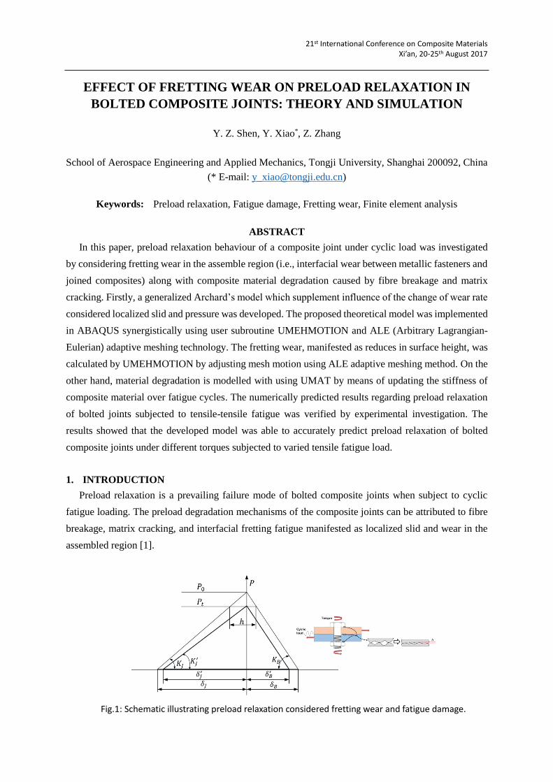
Fig.1: Schematic illustrating preload relaxation considered fretting wear and fatigue damage.
21st International Conference on Composite Materials Xi’an, 20-25th August 2017
2. EXPERIMENTAL INVESTIGATION
2.1 Material and specimen
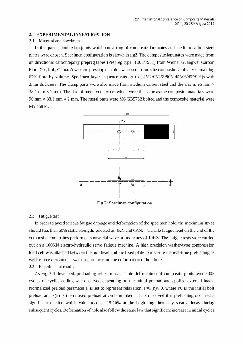
In this paper, double lap joints which consisting of composite laminates and medium carbon steel
plates were chosen. Specimen configuration is shown in fig2. The composite laminates were made from
unidirectional carbon/epoxy prepreg tapes (Prepreg type: T300/7901) from Weihai Guangwei Carbon
Fibre Co., Ltd., China. A vacuum pressing machine was used to cure the composite laminates containing
67% fibre by volume. Specimen layer sequence was set to [-45°2/0°/45°/90°/-45°/0°/45°/90°]s with
2mm thickness. The clamp parts were also made from medium carbon steel and the size is 96 mm ×
38.1 mm × 2 mm. The size of metal connectors which were the same as the composite materials were
96 mm × 38.1 mm × 2 mm. The metal parts were M6 GB5782 bolted and the composite material were
M5 bolted.
Fig.2: Specimen configuration
2.2 Fatigue test
In order to avoid serious fatigue damage and deformation of the specimen hole, the maximum stress
should less than 50% static strength, selected as 4KN and 6KN. Tensile fatigue load on the end of the
composite composites performed sinusoidal wave at frequency of 10HZ. The fatigue tests were carried
out on a 100KN electro-hydraulic servo fatigue machine. A high precision washer-type compression
load cell was attached between the bolt head and the fixed plate to measure the real-time preloading as
well as an extensometer was used to measure the deformation of bolt hole.
2.3 Experimental results
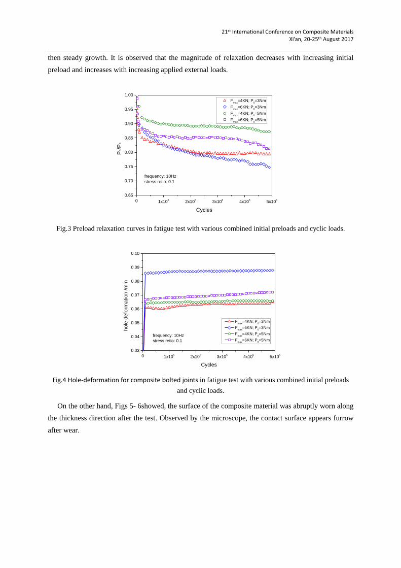
As Fig 3-4 described, preloading relaxation and hole deformation of composite joints over 500k
cycles of cyclic loading was observed depending on the initial preload and applied external loads.
Normalized preload parameter P is set to represent relaxation, P=P(n)/P0, where P0 is the initial bolt
preload and P(n) is the relaxed preload at cycle number n. It is observed that preloading occurred a
significant decline which value reaches 15-20% at the beginning then stay steady decay during
subsequent cycles. Deformation of hole also follow the same law that significant increase in initial cycles
21st International Conference on Composite Materials Xi’an, 20-25th August 2017
then steady growth. It is observed that the magnitude of relaxation decreases with increasing initial
preload and increases with increasing applied external loads.
0 1x10⁵
2x10⁵
3x10⁵
4x10⁵
5x10⁵
0.65
0.70
0.75
0.80
0.85
0.90
0.95
1.00
Fmax
=4KN; P0=3Nm
Fmax
=6KN; P0=3Nm
Fmax
=4KN; P0=5Nm
Fmax
=6KN; P0=5Nm
Pn/P
0
Cycles
frequency: 10Hz
stress retio: 0.1
Fig.3 Preload relaxation curves in fatigue test with various combined initial preloads and cyclic loads.
0 1x10⁵
2x10⁵
3x10⁵
4x10⁵
5x10⁵
0.03
0.04
0.05
0.06
0.07
0.08
0.09
0.10
Fmax
=4KN; P0=3Nm
Fmax
=6KN; P0=3Nm
Fmax
=4KN; P0=5Nm
Fmax
=6KN; P0=5Nm
hole
defo
rmation /m
m
Cycles
frequency: 10Hz
stress retio: 0.1
Fig.4 Hole-deformation for composite bolted joints in fatigue test with various combined initial preloads
and cyclic loads.
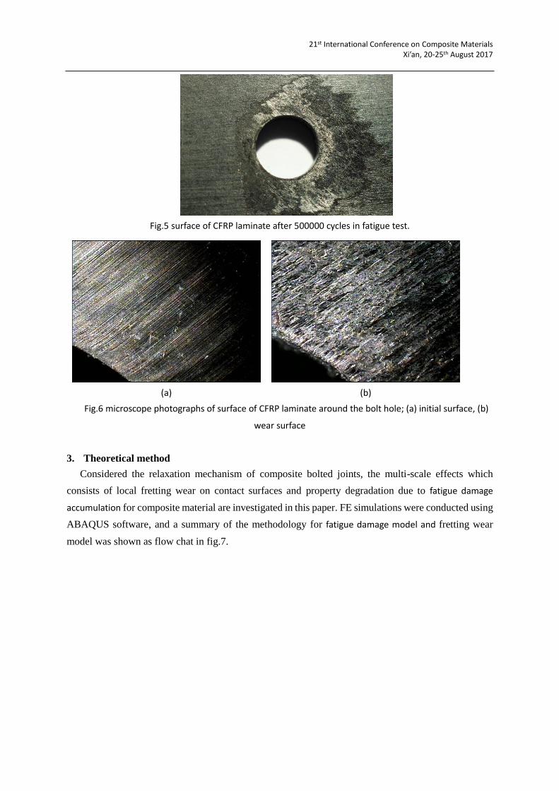
On the other hand, Figs 5- 6showed, the surface of the composite material was abruptly worn along
the thickness direction after the test. Observed by the microscope, the contact surface appears furrow
after wear.
21st International Conference on Composite Materials Xi’an, 20-25th August 2017
Fig.5 surface of CFRP laminate after 500000 cycles in fatigue test.
(a) (b)
Fig.6 microscope photographs of surface of CFRP laminate around the bolt hole; (a) initial surface, (b)
wear surface
3. Theoretical method
Considered the relaxation mechanism of composite bolted joints, the multi-scale effects which
consists of local fretting wear on contact surfaces and property degradation due to fatigue damage
accumulation for composite material are investigated in this paper. FE simulations were conducted using
ABAQUS software, and a summary of the methodology for fatigue damage model and fretting wear
model was shown as flow chat in fig.7.

21st International Conference on Composite Materials Xi’an, 20-25th August 2017
Experimental
tests
Composite laminates
Residual stiffness
Residual strength
Composite joints
Preload relaxation
Hole deformation
Fatigue damage model:
UMAT
Element stiffness
Ki
Archard wear model:
ALE+UMESHMOTION
Wear depth
Ui
Preload
relaxation
FEM
import
verify
Fig.7 Methodology to numerically model the preload relaxation in composite joints.
3.1 Progressive fatigue damage model
This paper uses a three-dimensional model developed by Shokrieh [2] to predict the progressive
fatigue damage of carbon/epoxy laminates in the bolted composite joints. This model describes the
material property degradation considering applied stress and fatigue cycle and can be expressed as
1/
log log 0.25, , 1 0
log log 0.25f
nR n r R
N
(1)
1/
log log 0.25, , 1 0
log log 0.25f f f
nE n r E
N
(2)
where , ,R n r denotes residual strength, , ,E n r denotes residual stiffness, 0R represents
static strength, 0E represents static stiffness, f signifies average strain to failure, α, β, λ and γ
are experimental curve fitting parameters. Those parameters were used in the FEA to predict the preload
relaxation, which are based on the Shokrieh‘s measured data (see Table 1-2).
Table1. The parameters for residual strength in the presented model.
Strength α β
Xt 10.03 0.473
Xc 49.06 0.25
Yt 9.6287 0.1255
21st International Conference on Composite Materials Xi’an, 20-25th August 2017
Yc 67.36 0.0011
S12 0.16 9.11
S13 0.2 12.0
Table2. The parameters for residual stiffness in the presented model.
stiffness λ γ
E11 14.57 0.3024
E22 14.77 0.1155
G12 0.7 11.0
Three-dimensional hashin criterion is used to determine composite material failure. Seven different
failure modes for the unidirectional ply are considered, i.e., fibre tension, fibre compression, fibre-matrix
shearing, matrix tension, matrix compression, normal tension and normal compression failure modes.
3.2 Wear model
When a bolted joint is applied with tightening torque, embedding occurs at the contact interface as a
result of plastic flattening of rough asperities at the contact surfaces [3]. Due to micro reciprocating
relative displacement between contact surfaces which are subject to pressure induced by the torque,
fretting wear presents at the contact interface. According to Archard model[4], the relationship between
local wear depth and sliding distance can be expressed as .
ℎ = 𝐾𝑝𝑝𝑠 (3)
where ℎ denotes wear depth, 𝐾𝑝 represents wear coefficient, 𝑝 signifies contact pressure and 𝑠 is
sliding distance.
Several authors have measured wear coefficient of epoxy composite which value is on the order of
10−8 𝑚𝑚3/𝑁𝑚𝑚. Freidrich et al. [5] investigate the effect of special filler on epoxy composite and
found that wear coefficient is in range of 2 − 22 × 10−9 𝑚𝑚3/𝑁𝑚𝑚. Wan [6] focused on the fiction
and wear characteristics of carbon fibre-epoxy composite under lubricated sliding conditions against a
(Friedrich, Zhang et al. 2005)medium-carbon steel counterface. The experimental result showed the
wear rate range from 2-50× 10−9 𝑚𝑚3/𝑁𝑚𝑚. In this simulation, wear coefficient is set to 2.5 ×
10−9 𝑚𝑚3/𝑁𝑚𝑚.
In bolted joints, load transfer between assembled members is mainly achieved by friction. When
contact surfaces become relatively smooth upon repeated friction, the contact performance of the
interface tends to be stable.
3.3 Numerical simulation
Based on previous analysis, finite element method is used to model preload relaxation of bolted
composite joints subject to tensile-tensile fatigue regarding interfacial fretting wear and material
degradation. The fretting wear, manifested as reduces in surface height, is calculated by
UMEHMOTION for ABAQUS according to Archard model and is modelled by adjusting mesh motion
using ALE adaptive meshing method. On the other hand, material degradation is modelled by updating
the stiffness of composite material over fatigue cycles using UMAT.
21st International Conference on Composite Materials Xi’an, 20-25th August 2017
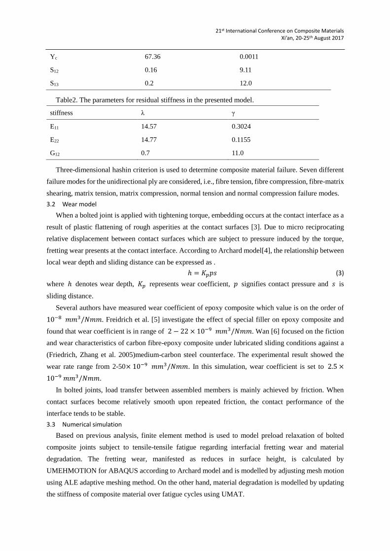
Fig.8 Synergistic implementation of user subroutine UMAT and UMESHMOTION in ABAQUS
4. Finite element analysis
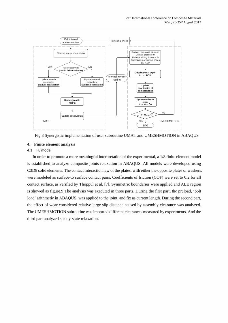
4.1 FE model
In order to promote a more meaningful interpretation of the experimental, a 1/8 finite element model
is established to analyze composite joints relaxation in ABAQUS. All models were developed using
C3D8 solid elements. The contact interaction law of the plates, with either the opposite plates or washers,
were modeled as surface-to surface contact pairs. Coefficients of friction (COF) were set to 0.2 for all
contact surface, as verified by Thoppul et al. [7]. Symmetric boundaries were applied and ALE region
is showed as figure.9 The analysis was executed in three parts. During the first part, the preload, ‘bolt
load’ arithmetic in ABAQUS, was applied to the joint, and fix as current length. During the second part,
the effect of wear considered relative large slip distance caused by assembly clearance was analyzed.
The UMESHMOTION subroutine was imported different clearances measured by experiments. And the
third part analyzed steady-state relaxation.
Call internal
access routine
Element stress, strain status
Failure analysis:
Hashin failure criterion
Update material
properties:
Sudden degradation
Update material
properties:
gradual degradation
internal access
routine
Contact nodes and element:
Contact pressure Pi
Relative sliding distance Si
Coordinates of contact nodes
(xi, yi, zi)
Update jacobin
matrix
Update
coordinates of
contact nodes
Remesh & sweep
end
Update stress,strain ? totalnn ? totalnn
Update number of
cycle:nnn
Update number of
cycle:nnn
Calculate wear depth:
iii SkPh Calculate wear depth:
iii SkPh
UMAT UMESHMOTION
YES NO
NO
YES
21st International Conference on Composite Materials Xi’an, 20-25th August 2017
Fig.9 Finite element model.
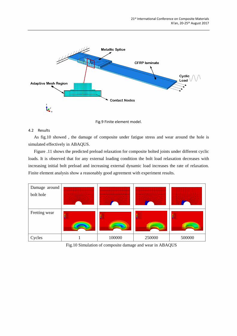
4.2 Results
As fig.10 showed , the damage of composite under fatigue stress and wear around the hole is
simulated effectively in ABAQUS.
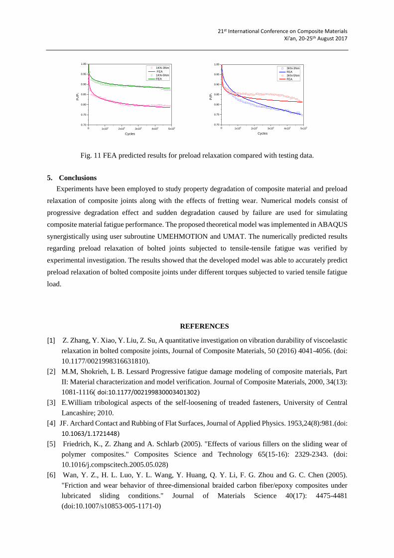
Figure .11 shows the predicted preload relaxation for composite bolted joints under different cyclic
loads. It is observed that for any external loading condition the bolt load relaxation decreases with
increasing initial bolt preload and increasing external dynamic load increases the rate of relaxation.
Finite element analysis show a reasonably good agreement with experiment results.
Damage around
bolt hole
Fretting wear
Cycles 1 100000 250000 500000
Fig.10 Simulation of composite damage and wear in ABAQUS
21st International Conference on Composite Materials Xi’an, 20-25th August 2017
0 1x10⁵
2x10⁵
3x10⁵
4x10⁵
5x10⁵
0.70
0.75
0.80
0.85
0.90
0.95
1.00
1KN-3Nm
FEA
1KN-5Nm
FEAP
n/P
0
Cycles
0 1x10⁵
2x10⁵
3x10⁵
4x10⁵
5x10⁵
0.70
0.75
0.80
0.85
0.90
0.95
1.00
3KN-3Nm
FEA
3KN-5Nm
FEA
Pt/P
0
Cycles
Fig. 11 FEA predicted results for preload relaxation compared with testing data.
5. Conclusions
Experiments have been employed to study property degradation of composite material and preload
relaxation of composite joints along with the effects of fretting wear. Numerical models consist of
progressive degradation effect and sudden degradation caused by failure are used for simulating
composite material fatigue performance. The proposed theoretical model was implemented in ABAQUS
synergistically using user subroutine UMEHMOTION and UMAT. The numerically predicted results
regarding preload relaxation of bolted joints subjected to tensile-tensile fatigue was verified by
experimental investigation. The results showed that the developed model was able to accurately predict
preload relaxation of bolted composite joints under different torques subjected to varied tensile fatigue
load.
REFERENCES
[1] Z. Zhang, Y. Xiao, Y. Liu, Z. Su, A quantitative investigation on vibration durability of viscoelastic
relaxation in bolted composite joints, Journal of Composite Materials, 50 (2016) 4041-4056. (doi:
10.1177/0021998316631810).
[2] M.M, Shokrieh, L B. Lessard Progressive fatigue damage modeling of composite materials, Part
II: Material characterization and model verification. Journal of Composite Materials, 2000, 34(13):
1081-1116( doi:10.1177/002199830003401302)
[3] E.William tribological aspects of the self-loosening of treaded fasteners, University of Central
Lancashire; 2010.
[4] JF. Archard Contact and Rubbing of Flat Surfaces, Journal of Applied Physics. 1953,24(8):981.(doi:
10.1063/1.1721448)
[5] Friedrich, K., Z. Zhang and A. Schlarb (2005). "Effects of various fillers on the sliding wear of
polymer composites." Composites Science and Technology 65(15-16): 2329-2343. (doi:
10.1016/j.compscitech.2005.05.028)
[6] Wan, Y. Z., H. L. Luo, Y. L. Wang, Y. Huang, Q. Y. Li, F. G. Zhou and G. C. Chen (2005).
"Friction and wear behavior of three-dimensional braided carbon fiber/epoxy composites under
lubricated sliding conditions." Journal of Materials Science 40(17): 4475-4481
(doi:10.1007/s10853-005-1171-0)

21st International Conference on Composite Materials Xi’an, 20-25th August 2017
[7] Thoppul, S. D., R. F. Gibson and R. A. Ibrahim (2008). "Phenomenological Modeling and
Numerical Simulation of Relaxation in Bolted Composite Joints." Journal of Composite Materials
42(17): 1709-1729.(doi: 10.1177/0021998308092544)