effect of feed composition on the selection of control...
TRANSCRIPT
Effect of Feed Composition on the Selection of Control Structuresfor High-Purity Binary Distillation
William L. Luyben*
Process Modeling and Control Center, Department of Chemical Engineering, Lehigh University,Bethlehem, Pennsylvania 18015
This paper discusses the selection of an effective control structure for a binary distillation columnproducing high-purity products. Results show that this selection depends on the feed composition.If the concentration of the light component is large, the reflux ratio is small. Control of a singleappropriate tray temperature by manipulating the reboiler heat input and using a fixed feed-to-reflux ratio provides effective control for both feed-rate and feed-composition disturbances.The reflux-drum level is controlled by the distillate flow rate. For intermediate concentrationsof the light component and for high-purity products, this study shows that a two-temperaturecontrol structure with reflux and reboiler heat input manipulated is required to handle feed-composition changes. Small concentrations of the light component yield small distillate flowrates and high reflux ratios. Conventional distillation control wisdom advises that the reflux-drum level should be controlled by the reflux flow rate when the reflux ratio is larger than ∼2.A control structure is frequently recommended in which the flow rate of the distillate is ratioedto the reflux. However, in many columns, a constant reflux-ratio strategy is not as effective asa constant reflux-to-feed strategy for maintaining product purity at both ends of the column inthe face of feed-composition disturbances when a single tray temperature is controlled. Analternative control structure is proposed in this paper that achieves the preferred constant reflux-to-feed strategy by controlling the reflux-drum level with reboiler heat input and manipulatingthe small distillate flow rate to control a tray temperature.
1. Introduction
The distillation control literature is one of the mostextensive in the area of process control. The last half ofthe 20th century produced thousands of papers andseveral books on the subject. The rate of publicationsduring the past decade has slackened significantlybecause of the de-emphasis on research in distillationby the funding agencies, which drives most academicstudies. However, distillation remains the primaryseparation method in the petroleum and chemicalindustries, and its practical importance is unquestion-able.
There are many different types of distillation columnsand many different types of control structures. Theselection of the “best” control structure is not as simpleas some papers claim. Factors that influence the selec-tion include volatilities, product purities, reflux ratio,column pressure, cost of energy, and column size.
This paper explores another factor that impacts theselection of an effective control structure: the composi-tion of the feed. We consider a binary system, with thespecific example of the methanol/water separation. Thissystem is important in itself, but it is also typical ofmany binary separations involving fairly high-purityproducts. In some processes, the concentration of thelight component in the feed is small (<10 mol %). Inother processes, it is large (>90 mol %). Other processeshave intermediate feed compositions.
A large concentration of the light component in thefeed corresponds to moderate reflux ratios, unlessrelative volatilities are quite small, because the distillate
flow rate is large. This means that the reflux-drum levelcan be controlled by either the reflux or the distillate.A control structure often recommended for low tomodest reflux ratio columns is the following:
1. Control the reflux-drum level by manipulating thedistillate.
2. Control an appropriate tray temperature by ma-nipulating the reboiler heat input.
3. Control the reflux-to-feed ratio (R/F) by measuringthe flow rate of the feed, multiplying this signal by thedesired reflux-to-feed ratio, and setting the setpoint ofa remote-set flow controller on the reflux.
4. Control the base level by manipulating the bottomsflow rate.
5. Control the pressure by manipulating the con-denser heat removal.
A small concentration of the light component in thefeed means large reflux ratios because the distillate flowrate is small. Conventional distillation control heuristicsadvise that the reflux-drum level should be controlledby the reflux flow rate when the reflux ratio is largerthan ∼2 or 3. Therefore, a control structure oftenrecommended for high reflux ratio columns is thefollowing:
1. Control the reflux-drum level by manipulating thereflux.
2. Control an appropriate tray temperature by ma-nipulating the reboiler heat input.
3. Control the reflux ratio by measuring the flow rateof the reflux, multiplying this signal by the reciprocalof the desired reflux ratio, and setting the setpoint of aremote-set flow controller on the distillate.
4. Control the base level by manipulating the bottomsflow rate.* Tel.: (610) 758-4256. E-mail: [email protected].
7800 Ind. Eng. Chem. Res. 2005, 44, 7800-7813
10.1021/ie0580147 CCC: $30.25 © 2005 American Chemical SocietyPublished on Web 09/02/2005
5. Control the pressure by manipulating the con-denser heat removal.
When the control structure features the control of asingle temperature, the remaining control degree offreedom must be specified. The two most commonalternatives are constant reflux ratio and constantreflux-to-feed ratio. They are both equally effective inhandling feed flow rate disturbances. In many separa-tions, the constant reflux-to-feed structure (R/F) pro-vides better steady-state product purities for changesin feed composition than the constant reflux ratiostructure (RR)1. This is demonstrated later in this paperfor the specific chemical components used in the ex-ample.
The control of two temperatures instead of a singletemperature is sometimes discussed in the literature,but it is not clear when this more complex controlstructure is really required. The presence of the interac-tion between the two temperature loops makes control-ler tuning more difficult. However, dual-temperaturecontrol has the potential advantage of maintaining thepurities of both the distillate and the bottoms productscloser to the desired specifications.
2. Process Studied
The binary distillation of methanol/water is used asa numerical example in this paper, but the resultsshould be applicable to many binary separations. Theseparation of methanol from water is a very commonand important distillation system. Methanol is usuallyproduced from synthesis gas, a mixture of hydrogen,carbon monoxide, and carbon dioxide, which typicallycomes from a steam/methanol reforming process. Wateris also produced in the methanol reactor and must beremoved.
There has been an enormous interest in the “hydrogeneconomy” in recent years. From a purely technicalperspective, much of this appears to be hype. A “metha-nol economy” seems to be much more realistic techni-cally, since synthesis gas can be produced by the partialoxidation of any combustible hydrocarbon, includingrenewable sources such as trees and agricultural byprod-ucts. Methanol is a convenient fuel for automobiles, asdemonstrated by its use in World War II for tank fuel.The future uses of methanol may be much moreextensive than present consumption. In any event, themethanol/water separation provides a typical exampleof a binary high-purity separation problem.
In the following sections, distillation columns aredesigned for a range of feed compositions: 10, 20, 40,60, 80, and 90 mol % methanol. Each column isoptimized in terms of steady-state economics, yieldingcolumns with different numbers of trays, different feedtrays, and different reflux ratios. Then the dynamiccontrol of each is explored.
The simulations use the rigorous nonlinear modelsin the commercial simulation tools Aspen Plus andAspen Dynamics. The van Laar physical property pack-age is used because of its known ability to closely matchexperimental methanol/water vapor-liquid equilibriumdata. All columns operate at atmospheric pressure witha 0.0068 atm pressure drop per tray. The feed flow rateis 1 kmol/s. The Aspen tray numbering notation is used(stages numbered from the reflux drum down to thereboiler). Total condensers, partial reboilers, and theo-retical trays are used. We consider in this paper acolumn producing high purity products at both ends.
The purities of distillate and bottoms streams are setat 99.9 mol %. The Aspen “Design Spec-Vary” featureis used to adjust the distillate-to-feed ratio and thereflux ratio to achieve these purities.
3. Steady-State Design
The economic objective function is the minimum totalannual cost (TAC), which includes both energy andcapital costs. Table 1 gives the economic parameters.Column diameters are calculated by the Aspen traysizing procedure. Column height is calculated assuminga 0.61-m spacing per tray and 20% additional shelllength for base, feed, and overhead volume.
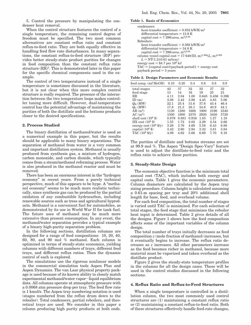
For each feed composition, the total number of stagesis varied until TAC is minimized. For each selection oftotal stages, the feed stage that minimizes the reboilerheat input is determined. Table 2 gives details of allthe designs. Figure 1 shows how the feed compositionaffects some of the important variables of the columndesign.
The total number of trays initially decreases as feedcomposition z (mole fraction of methanol) increases, butit eventually begins to increase. The reflux ratio de-creases as z increases. All other parameters increaseas the feed becomes richer in methanol, because morematerial must be vaporized and taken overhead as thedistillate product.
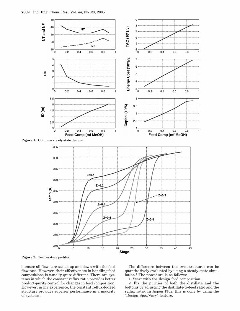
Figure 2 gives the steady-state temperature profilesin the columns for all the design cases. These will beused in the control studies discussed in the followingsections.
4. Reflux Ratio and Reflux-to-Feed Structures
When a single temperature is controlled in a distil-lation column, the two most commonly used controlstructures are (1) maintaining a constant reflux ratioor (2) maintaining a constant reflux-to-feed ratio. Bothof these structures effectively handle feed-rate changes,
Table 1. Basis of Economics
condensers:heat-transfer coefficient ) 0.852 kW/K‚m2
differential temperature ) 13.9 Kcapital cost ) 7 296(area, m2)0.65
Reboilers:heat-transfer coefficient ) 0.568 kW/K‚m2
differential temperature ) 34.8 Kcapital cost ) 7 296(area, m2)0.65
column vessel capital cost ) 17 640(ID, m)1.066(L, m)0.802
L ) NT(1.2)(0.61 m/tray)energy cost ) $4.7 per 106 kJTAC ) [(capital cost)/(payback period)] + energy costpayback period ) 3 years
Table 2. Design Parameters and Economic Results
feed comp. (mf MeOH) 0.10 0.20 0.4 0.6 0.8 0.9
total stages 42 37 32 32 37 32feed stage 13 14 16 19 25 21RR 4.11 2.04 1.00 0.645 0.456 0.396ID (m) 3.08 3.42 3.98 4.45 4.83 5.06QR (MW) 22.1 25.4 31.6 37.6 43.4 46.4QC (MW) 17.8 21.3 28.1 34.6 40.9 44.1AR (m2) 1120 1280 1600 1900 2190 2340AC (m2) 1500 1800 2370 2920 3450 3720shell cost (106 $) 0.879 0.881 0.916 1.83 1.27 1.18HX cost (106 $) 1.55 1.72 2.02 2.29 2.54 2.66energy cost (106 $/y) 3.28 3.76 4.69 5.58 6.43 6.88capital (106 $) 2.42 2.60 2.94 3.32 3.81 3.84TAC (106 $/y) 4.09 4.62 5.66 6.69 7.70 8.16
Ind. Eng. Chem. Res., Vol. 44, No. 20, 2005 7801
because all flows are scaled up and down with the feedflow rate. However, their effectiveness in handling feedcompositions is usually quite different. There are sys-tems in which the constant reflux ratio provides betterproduct-purity control for changes in feed composition.However, in my experience, the constant reflux-to-feedstructure provides superior performance in a majorityof systems.
The difference between the two structures can bequantitatively evaluated by using a steady-state simu-lation.1 The procedure is as follows:
1. Start with the design feed composition.2. Fix the purities of both the distillate and the
bottoms by adjusting the distillate-to-feed ratio and thereflux ratio. In Aspen Plus, this is done by using the“Design-Spec/Vary” feature.
Figure 1. Optimum steady-state designs.
Figure 2. Temperature profiles.
7802 Ind. Eng. Chem. Res., Vol. 44, No. 20, 2005

3. Run a number of steady-state cases with differentfeed compositions.
4. Plot the resulting reflux flow rates and reflux ratiosthat are required to maintain product purities over thisrange of feed compositions.
5. Select the variable with the lesser variability.The results of applying this method to the methanol/
water system are given in Table 3 for design cases withthree different feed compositions. For the 10 mol %methanol feed design case, the feed composition isvaried from 5 to 15 mol %, and the required reflux ratioand reflux-to-feed ratio are calculated. The changes inthe reflux-to-feed ratio are much smaller than those ofthe reflux ratio. The reflux-to-feed ratio only changes∼1% over the entire range of feed compositions, whilethe reflux ratio changes by a factor of 3.
These results indicate that the constant reflux-to-feedstrategy will maintain product purities closer to theirspecified values. Similar results for other design feedcases (40 and 90 mol % methanol) are also shown inTable 3. The higher the feed composition, the smallerthe difference between the two structures. For example,in the 90 mol % case, the change in the reflux ratio is∼34% while the change in the reflux-to-feed is ∼11%.
It is clear that the reflux-to-feed structure is preferredin the methanol/water separation, particularly at lowfeed compositions. The dilemma is that, at the low feedcompositions, the reflux ratio is high. Conventionalwisdom says that, in high reflux ratio columns, thereflux-drum level should be controlled by reflux. Thisprecludes the use of a reflux-to-feed structure. So thereis a conflict between these two suggested control struc-tures. In the next section, we propose a control structurethat satisfies both objectives.
Since the small feed composition case presents themost serious conflict between the RR and R/F struc-tures, we begin with an examination of this case. Thecontrol of a single tray temperature with the two waysto manage the reflux will be tested. In subsequentsections, other feed compositions will be explored, andwe will find that the most effective control structurechanges as the feed composition changes.
5. Feed Composition 10 mol % Methanol
The economic optimum column has 42 total stagesand is fed on Stage 13. The important parameter in thiscase is the reflux ratio, which is high at 4.11 becausethe distillate flow rate is small (only 10% of the feed).
The first issue is the selection of which tray temper-ature to control. A common distillation control heuristicis to select a tray where the change in temperature fromtray to tray is the largest (steep temperature profile).
Figure 2 gives temperature profiles for all the cases. Thez ) 0.1 profile has its maximum slope at Stage 7. Notethat this is above the feed stage in the rectifying section.At this location, either the reflux or the vapor boilupcan be used to control temperature. Changes in vaporrates affect the temperatures on all trays quickly, sovapor boilup can be used to control a temperature atany location in the column. Changes in reflux havesignificant hydraulic lags (3-6 s per tray), so usingreflux to control a temperature far down in the columnshould be avoided. However, in this case, Stage 7 is onlysix trays down in the column, so reflux could be used.
5.1. S7-RR Structure. We start by assuming thatthe high reflux ratio requires the control of the reflux-drum level by manipulating the reflux flow rate. Figure3A gives the Aspen Dynamics flowsheet and shows thecontroller faceplates. The distillate flow rate is ratioedto the reflux flow rate (note in the “FCD” faceplate thatthis controller is on “cascade”). Stage 7 is controlled bymanipulating the reboiler heat input. A 1-min deadtimeis used in the temperature loop, and 100-K temperaturetransmitter spans are used. The relay-feedback test isrun to determine the ultimate gain and period, and theTyreus-Luyben tuning rules are used (KC ) 0.67 andτI ) 13 min). The column base and the reflux drum aresized to give 5-min holdup times when 50% full, basedon the total liquid entering or leaving. Proportional levelcontrollers with KC ) 2 are used.
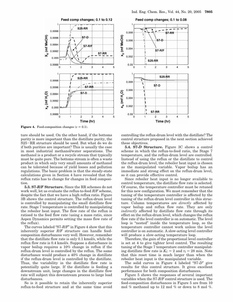
This RR control structure handles changes in feedflow rate quite well. However, it does not handledisturbances in feed composition. Figure 4 gives product-purity results for several control structures. The curveslabeled “S7-RR” refer to the structure in which thereflux ratio and the Stage 7 temperature are controlled.An increase in the feed composition from 10 to 12 mol% methanol (the left two graphs) does not cause aproblem in terms of the purities of both the bottoms anddistillate purities. Both the distillate purity xD and thebottoms purity xB remain near the desired 0.999 mf.However, a decrease in the feed composition from 10 to8 mol % methanol (the right two graphs) produces adrastic drop in the purity of the bottoms. Clearly, thisstructure does not provide effective control of productpurities for feed-composition disturbances.
5.2. S25-RR Structure. Since a temperature nearthe top of the column is being controlled, it is reasonablethat the distillate purity stays fairly close to its speci-fication, while the bottoms purity does not. One mightconclude that a tray down further in the column mightgive better control of the bottoms purity. Looking againat the temperature profile for the z ) 0.1 case in Figure2, we can see another region where the temperature ischanging from tray to tray. This occurs at Stage 25,which is much lower in the column. The temperaturecontroller is retuned, giving KC ) 4.3 and τI ) 5.3 min.Note that this gain is larger than the previous gainwhen Stage 7 temperature is controlled, which is dueto the smaller process gain on Stage 25 (temperatureprofile less steep).
Results for using this control tray are also shown inFigure 4 in the curves labeled “S25-RR.” This structuredoes a good job in controlling the bottoms compositionfor both positive and negative changes in the feedcomposition. However, now the distillate purity dropsdrastically for an increase in feed composition.
We could conclude that, if the distillate purity is moreimportant than the bottoms purity, the S7-RR struc-
Table 3. Comparison of Reflux Ratio and Reflux-to-FeedStructures (for Feed Flow Rate ) 1 kmol/s)
design feed comp. z(mf MeOH) z reflux-to-feed ratio reflux ratio
0.1 0.05 0.4095 8.3410.08 0.4094 5.1720.10 0.4076 4.1090.12 0.4061 3.4060.15 0.4049 2.712
0.4 0.35 0.4068 1.1630.4 0.4013 1.0040.45 0.3981 0.8846
0.9 0.85 0.3676 0.43210.9 0.3567 0.39600.95 0.3303 0.3474
Ind. Eng. Chem. Res., Vol. 44, No. 20, 2005 7803

Figure 3. (A) RR control structure with temperature control using QR. (B) R/F control structure with temperature control using QR. (C)R/F control structure with temperature control using D.
7804 Ind. Eng. Chem. Res., Vol. 44, No. 20, 2005
ture should be used. On the other hand, if the bottomspurity is more important than the distillate purity, theS25-RR structure should be used. But what do we doif both purities are important? This is usually the casein most industrial methanol/water separations. Themethanol is a product or a recycle stream that typicallymust be quite pure. The bottoms stream is often a wasteproduct in which only very small amounts of methanolcan be tolerated because of yield losses and pollutionregulations. The basic problem is that the steady-statecalculations given in Section 4 have revealed that thereflux ratio has to change for changes in feed composi-tion.
5.3. S7-R/F Structure. Since the RR schemes do notwork well, let us evaluate the reflux-to-feed R/F scheme,despite the fact that we have a high reflux ratio. Figure3B shows the control structure. The reflux-drum levelis controlled by manipulating the small distillate flowrate. Stage 7 temperature is controlled by manipulatingthe reboiler heat input. The flow rate of the reflux isratioed to the feed flow rate (using a mass ratio, sinceAspen Dynamics permits setting the mass flow rate ofthe reflux).
The curves labeled “S7-R/F” in Figure 4 show that thisinherently superior R/F structure can handle feed-composition disturbances very well. However, rememberthat the distillate flow rate is only 0.1 kmol/s, while thereflux flow rate is 0.4 kmol/s. Suppose a disturbance invapor boilup requires a 10% change in reflux if thereflux-drum level is controlled by the reflux. The samedisturbance would produce a 40% change in distillateif the reflux-drum level is controlled by the distillate.Thus, the variability in the distillate flow rate ispotentially quite large. If the distillate is feeding adownstream unit, large changes in the distillate flowrate will subject this downstream process to large loaddisturbances.
So is it possible to retain the inherently superiorreflux-to-feed structure and at the same time avoid
controlling the reflux-drum level with the distillate? Thecontrol structure proposed in the next section achievedthese objectives.
5.4. S7-D Structure. Figure 3C shows a controlscheme in which the reflux-to-feed ratio, the Stage 7temperature, and the reflux-drum level are controlled.Instead of using the reflux or the distillate to controlthe reflux-drum level, the reboiler heat input is chosenas the manipulated variable. Vapor boilup has animmediate and strong effect on the reflux-drum level,so it can provide effective control.
Since reboiler heat input is no longer available tocontrol temperature, the distillate flow rate is selected.Of course, the temperature controller must be retunedfor this new configuration. We must remember that thetuning of the temperature controller is affected by thetuning of the reflux-drum level controller in this struc-ture. Column temperatures are directly affected byvapor boilup and reflux flow rate. They are onlyindirectly affected by distillate flow rate through itseffect on the reflux-drum level, which changes the refluxflow rate if the level controller is on automatic. The levelloop is “nested” inside the temperature loop, so thetemperature controller cannot work unless the levelcontroller is on automatic. A slow-acting level controllerwill produce a slow-acting temperature loop.
Therefore, the gain of the proportional level controlleris set at 4 to give tighter level control. The resultingtuning of the Stage 7 temperature controller manipulat-ing distillate flow rate is KC ) 2 and τI ) 28 min. Notethat this reset time is much larger than when thereboiler heat input is the manipulated variable.
The solid curves in Figure 4 labeled “S7-D” giveresults for this control structure. It gives excellentperformance for both composition disturbances.
Figure 5 shows the responses of several importantvariables when the S7-R/F control structure is used. Thefeed-composition disturbances in Figure 5 are from 10mol % methanol up to 12 mol % or down to 8 mol %.
Figure 4. Feed-composition changes (z ) 0.1).
Ind. Eng. Chem. Res., Vol. 44, No. 20, 2005 7805

Note the smooth changes in the flow rates of both ofthe product streams because of the proportional levelcontrollers.
Figure 6 shows the responses of several importantvariables when the S7-D control structure is used forfeed-composition disturbances. The magnitudes of thetransient deviations in Stage 7 temperature are largerthan those for the S7-QR structure, but the deviationsin the purities of the products are about the same.
Now that we have developed an effective controlstructure for the case with a 10 mol % methanol feed
composition, let us see if this structure is required andis effective for higher feed compositions.
6. Feed Composition 20 mol % Methanol
The economic optimum column has 37 total stagesand is fed on Stage 14. The reflux ratio is 2.044, whichis small enough so that the reflux-drum level can becontrolled by either the distillate or the reflux. Thetemperature profile for the z ) 0.2 case, given in Figure2, shows a steep profile at Stage 7 in the rectifying
Figure 5. S7-R/F: feed-composition changes (z ) 0.1).
Figure 6. S7 controlled by D: feed-composition changes (z ) 0.1).
7806 Ind. Eng. Chem. Res., Vol. 44, No. 20, 2005

section. Therefore, we use the reflux-to-feed ratio andcontrol Stage 7 with the vapor boilup.
The effectiveness of this structure is illustrated inFigure 7 for composition disturbances. The feed com-position is changed from 20 mol % methanol to 24 mol% or 16 mol %. The increase in feed composition is well-handled. The decrease causes the bottoms purity to dropfrom 99.9 mol % methanol to a little below 99.6 mol %methanol, which is still reasonably close to specification.
These results indicate that controlling a suitable traytemperature and using a reflux-to-feed ratio providesquite effective control for the 20 mol % feed-compositionsystem.
Now let us see what happens as we go to still higherfeed compositions.
7. Feed Composition 40 mol % Methanol
The economic optimum column has 32 total stagesand is fed on Stage 16. The reflux ratio is 1.044, so thereflux-drum level can be controlled by either the distil-late or the reflux. The temperature profile for the z )0.4 case given in Figure 2 shows that the location ofthe steepest part has shifted to the stripping section ofthe column (Stage 24).
7.1. S24-R/F Structure. We start by evaluating thecontrol structure that uses a reflux-to-feed ratio andcontrols Stage 24 with the vapor boilup. This is a single-end control structure in which one temperature iscontrolled and the other degree of freedom is used toset the reflux flow rate. The temperature controllertuning constants are KC ) 3.8 and τI ) 6.6 min.
Figure 8 gives results for feed-composition distur-bances from 40 mol % methanol up to 48 mol % anddown to 32 mol %. The solid curves labeled “S24” arefor the case when Stage 24 is controlled. The increasein feed composition can be handled, but the decreaseresults in the distillate purity dropping below 98 mol%. Remember that the temperature being controlled is
now in the stripping section, so the control of thebottoms purity should be better than that of the distil-late purity.
Suppose we select a tray in the rectifying sectionwhere there is a reasonably steep temperature profile.The responses shown in the dashed curves in Figure 8labeled “S9” are achieved by using Stage 9 and retuningthe temperature controller (KC ) 4.7 and τI ) 7.9 min).Now the bottoms purity drops below 98 mol % for thefeed-composition decrease.
These results show that, despite using the preferredreflux-to-feed structure, a single-temperature controlstructure cannot maintain the purities of both productsfor feed-composition disturbances. Therefore, for col-umns with a feed composition of 40 mol % methanol, a“dual-temperature” control structure is required.
7.2. Dual-Temperature Structure. The need tocontrol two temperatures creates a more difficult controlproblem because of the potential for interaction betweenthe control loops. The tuning of two controllers in a 2 ×2 multivariable system and the selection of what twotemperatures to control require more analysis than asimple single-temperature SISO (single-input, single-output) structure. Certainly, simplicity is a very desir-able feature in any process control system. However,the requirements of the process dictate that a morecomplex control structure is needed for the methanol/water separation when the feed composition is around40 mol % methanol.
7.2.A. Selection of Control Tray Locations. Thefirst issue is to select two appropriate tray locations fortemperature control. Singular value decomposition2
(SVD) gives some guidance for selecting the mostsensitive tray locations in a multivariable control struc-ture. The first job is to find the steady-state gain matrixrelating all the tray temperatures to the two manipu-lated variables (reflux and reboiler heat input). Thesegains can be found numerically using the steady-statesimulator. Two runs are required, one for each of the
Figure 7. S7 R/F: feed-composition changes (z ) 0.2).
Ind. Eng. Chem. Res., Vol. 44, No. 20, 2005 7807

inputs. A very small change (0.01% of the steady-statevalue) is made in the reflux flow rate with the reboilerheat input fixed. Note that the “Design Spec/Vary”feature is not used for these “open loop” runs. Theresulting temperature on each tray is subtracted fromthe original temperature to calculate the deviation.Dividing this by the change in the reflux gives the open-loop process gain between the tray temperature and thereflux. Then the procedure is repeated for a very smallchange in the reboiler heat input with the reflux flowrate fixed.
These steady-state gains are shown in the uppergraph in Figure 9. The dashed curves are for changesin the reboiler heat input QR. The solid curves are forchanges in the reflux R. As expected, the gains arepositive for QR and negative for R. The steady-state gainmatrix is decomposed, using the SVD function inMatlab. The resulting two vectors of the U matrix aregiven in the lower graph in Figure 9. The peaks in theU curves indicate the most sensitive stages from asteady-state standpoint. Stages 9 and 24, which we usedfor the single-temperature control structures based on
Figure 8. S24 and S9 R/F: feed-composition changes (z ) 0.4).
Figure 9. Gains and SVD analysis; 0.01% changes in R and QR (z ) 0.4).
7808 Ind. Eng. Chem. Res., Vol. 44, No. 20, 2005
simply looking at the shape of the temperature profile,are located at or very near the peaks.
The magnitudes of the R and QR peaks in the Ucurves are not significantly different, so SVD analysissuggests that either set of pairings could be used.However, a common-sense consideration of the dynam-ics suggests that we select the reflux to control thetemperature of Stage 9 near the top of the column andthe reboiler heat input to control the temperature ofStage 24 near the bottom. Note that the Stage 9controller is direct acting, and the Stage 24 controlleris reverse acting.
7.2.B. Controller Tuning. The second issue is totune the controllers in the multivariable environment.A “sequential” method is used in this paper. The refluxflow rate is fixed, and the Stage 24 temperature control-ler is tuned using a relay-feedback test and the Tyreus-Luyben tuning constants (which are KC ) 3.8 and τI )6.6 min, the same as reported previously for SISOcontrol). This loop is selected to tune first because thedynamics between the temperature and the reboilerheat input are faster than the dynamics between thetemperature and the reflux.
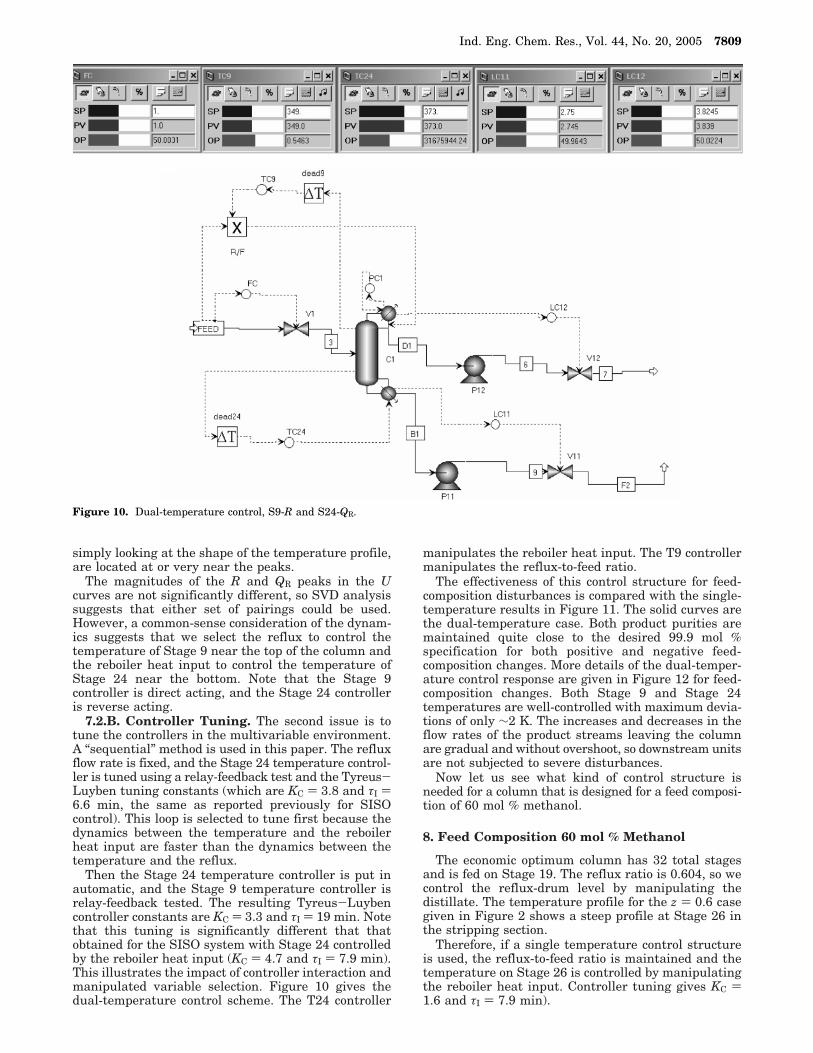
Then the Stage 24 temperature controller is put inautomatic, and the Stage 9 temperature controller isrelay-feedback tested. The resulting Tyreus-Luybencontroller constants are KC ) 3.3 and τI ) 19 min. Notethat this tuning is significantly different that thatobtained for the SISO system with Stage 24 controlledby the reboiler heat input (KC ) 4.7 and τI ) 7.9 min).This illustrates the impact of controller interaction andmanipulated variable selection. Figure 10 gives thedual-temperature control scheme. The T24 controller
manipulates the reboiler heat input. The T9 controllermanipulates the reflux-to-feed ratio.
The effectiveness of this control structure for feed-composition disturbances is compared with the single-temperature results in Figure 11. The solid curves arethe dual-temperature case. Both product purities aremaintained quite close to the desired 99.9 mol %specification for both positive and negative feed-composition changes. More details of the dual-temper-ature control response are given in Figure 12 for feed-composition changes. Both Stage 9 and Stage 24temperatures are well-controlled with maximum devia-tions of only ∼2 K. The increases and decreases in theflow rates of the product streams leaving the columnare gradual and without overshoot, so downstream unitsare not subjected to severe disturbances.
Now let us see what kind of control structure isneeded for a column that is designed for a feed composi-tion of 60 mol % methanol.
8. Feed Composition 60 mol % Methanol
The economic optimum column has 32 total stagesand is fed on Stage 19. The reflux ratio is 0.604, so wecontrol the reflux-drum level by manipulating thedistillate. The temperature profile for the z ) 0.6 casegiven in Figure 2 shows a steep profile at Stage 26 inthe stripping section.
Therefore, if a single temperature control structureis used, the reflux-to-feed ratio is maintained and thetemperature on Stage 26 is controlled by manipulatingthe reboiler heat input. Controller tuning gives KC )1.6 and τI ) 7.9 min).
Figure 10. Dual-temperature control, S9-R and S24-QR.
Ind. Eng. Chem. Res., Vol. 44, No. 20, 2005 7809

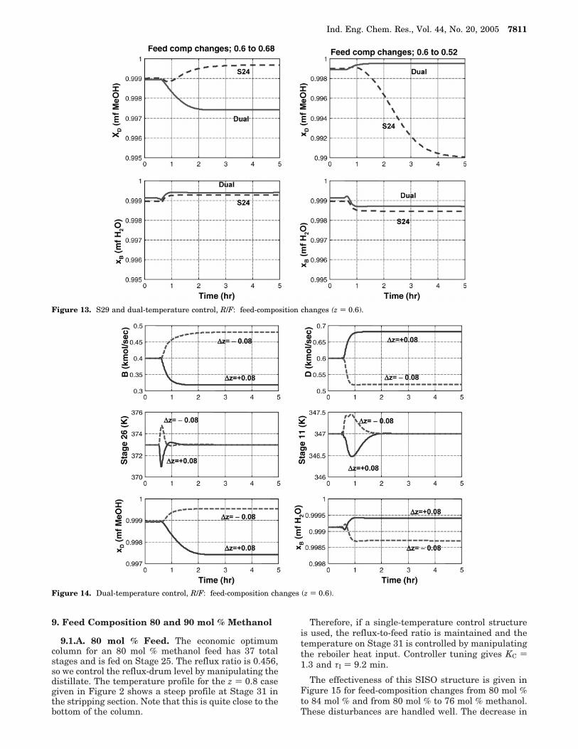
The effectiveness of this SISO structure is given inFigure 13 (the dashed lines) for feed-composition changesfrom 60 mol % to 68 mol % and from 60 mol % to 52mol % methanol. The purity of the distillate drops below99 mol % for the decrease in feed composition. So dual-temperature control is needed.
Stage 11 is selected for the second control tray and iscontrolled by manipulating the reflux-to-feed ratio.Sequential tuning gives controller settings for this loopof KC ) 4.5 and τI ) 21 min.
The effectiveness of this 2 × 2 structure (the solidlines) is compared with the SISO structure in Figure13 for feed-composition changes. The dual-temperaturecontrol structure does an excellent job in maintainingproduct purities. More details are given in Figure 14,which shows the responses to feed-composition distur-bances.
Let us now see what happens for even larger feedcompositions.
Figure 11. S24, S9 and dual-temperature control: feed-composition changes (z ) 0.4).
Figure 12. Dual-temperature control, R/F: feed-composition changes (z ) 0.4).
7810 Ind. Eng. Chem. Res., Vol. 44, No. 20, 2005
9. Feed Composition 80 and 90 mol % Methanol
9.1.A. 80 mol % Feed. The economic optimumcolumn for an 80 mol % methanol feed has 37 totalstages and is fed on Stage 25. The reflux ratio is 0.456,so we control the reflux-drum level by manipulating thedistillate. The temperature profile for the z ) 0.8 casegiven in Figure 2 shows a steep profile at Stage 31 inthe stripping section. Note that this is quite close to thebottom of the column.
Therefore, if a single-temperature control structureis used, the reflux-to-feed ratio is maintained and thetemperature on Stage 31 is controlled by manipulatingthe reboiler heat input. Controller tuning gives KC )1.3 and τI ) 9.2 min.
The effectiveness of this SISO structure is given inFigure 15 for feed-composition changes from 80 mol %to 84 mol % and from 80 mol % to 76 mol % methanol.These disturbances are handled well. The decrease in
Figure 13. S29 and dual-temperature control, R/F: feed-composition changes (z ) 0.6).
Figure 14. Dual-temperature control, R/F: feed-composition changes (z ) 0.6).
Ind. Eng. Chem. Res., Vol. 44, No. 20, 2005 7811

feed composition results in a slow decrease in thedistillate purity, but it only drops to ∼99.75 mol %methanol.
9.1.B. 90 mol % Feed. The economic optimumcolumn for a 90 mol % methanol feed has 32 total stagesand is fed on Stage 21. The reflux ratio is 0.396, so wecontrol the reflux-drum level by manipulating thedistillate. The temperature profile for the z ) 0.9 casegiven in Figure 2 shows a steep profile at Stage 27 inthe stripping section.
Therefore, if a single-temperature control structureis used, the reflux-to-feed ratio is maintained and thetemperature on Stage 27 is controlled by manipulatingthe reboiler heat input. Controller tuning gives KC )1.8 and τI ) 7.9 min.
The effectiveness of this SISO structure is given inFigure 16 for feed-composition changes from 90 mol %to 92 mol % and from 90 mol % to 88 mol % methanol.Both disturbances are handled well.
Figure 15. S31 R/F: feed-composition changes (z ) 0.8).
Figure 16. S27 R/F: feed-composition changes (z ) 0.9).
7812 Ind. Eng. Chem. Res., Vol. 44, No. 20, 2005

These results indicate that a dual-temperature controlstructure is not needed at high feed concentrations.
10. Other Systems
The numerical example used in this study is themethanol/water separation, which has nonideal vapor-liquid equilibrium and relative volatilities that rangefrom ∼2 to 5 over the composition space. We alsoconsider high-purity products (99.9%). Are the resultsapplicable to other systems?
We believe the results can be extended to otherchemical systems that produce high-purity products.Several other systems have been studied, and resultsindicate that there is less need for dual-temperaturecontrol in columns producing low-purity products.
For example, a propane/isobutane separation wasstudied with product purities of 98%. The economicoptimum column for a feed composition of 40 mol %propane has 37 stages and operates at 13.5 atm with areflux ratio of 2.73. The constant reflux-to-feed ratio ispreferred in this system. Controlling a single traytemperature (Stage 7) and changing feed compositionover the range of 32-48 mol % propane resulted inchanges in distillate purity from 98.41 to 97.51 mol %propane and changes in bottoms purity from 98.08 to98.77 mol % isobutane. If these fairly small changes inproduct purities are acceptable, there is no need fordual-temperature control. Similar results were seen inthe benzene/toluene system. The results of this paperare limited to high-purity columns.
11. Conclusion
This paper presents a methodology for exploring theeffect of feed composition on control structure for abinary, high-purity distillation column that depends onthe feed composition. The binary distillation of methanol/water is used as a numerical example in this paper, butthe results should be applicable to many binary separa-tions.
Dual-temperature control is required for intermediatefeed compositions, but single-temperature control isadequate for either low or high feed compositions. Forthe methanol/water separation, the reflux-to-feed struc-ture should be used throughout the range of feedcompositions. At low feed compositions, this presents adilemma because of the high reflux ratio, which nor-mally requires that the reflux be used to control thereflux-drum level. A control structure is proposed thatovercomes this difficulty: control the reflux-drum levelwith the reboiler heat input and control a tray temper-
ature with the distillate. Fortunately, the location of theappropriate control tray is up in the rectifying section,so temperature control using the distillate is effective.
Dynamic simulations have been used to assess controlstructure effectiveness. It should be noted that, if oneis only interested in the steady-state effect of changingfeed composition with a given control structure, asteady-state simulation can be used. For example, if thefixed reflux-to-feed and single-tray-temperature controlstructure is to be evaluated, the “Design Spec-Vary”capability in Aspen Plus can be used with the refluxflow rate fixed and the selected stage temperature fixed.Then feed composition is changed over the expectedrange, and the new steady-state values of xD and xBshow how much change there is in product purities asthe feed composition changes.
Nomenclature
AC ) heat transfer area of condenser (m2)AR ) heat transfer area of reboiler (m2)B ) bottoms flow rate (kmol/sec)D ) distillate flow rate (kmol/sec)HX ) heat exchangerID ) column diameter (m)L ) length of column (m)NF ) feed stageNT ) total number of stagesQC ) condenser heat removal (MW)QR ) reboiler heat input (MW)R ) reflux flow rate (kmol/sec)R/F ) reflux-to-feed ratioRR ) reflux ratio ) R/DSn ) stage number for temperature controlTAC ) total annual cost (106 $/y)xB ) composition of bottoms product (mf water)xD ) composition of distillate product (mf methanol)z ) composition of feed (mf methanol)∆F ) change in feed flow rate∆z ) change in feed composition
Literature Cited
(1) Luyben, W. L. Steady-state energy-conservation aspects ofdistillation control system design. Ind. Eng. Chem. Fundam. 1975,14, 321.
(2) Moore, C. F. Selection of controlled and manipulatedvariables. In Practical Distillation Control; Van Nostrand Rein-hold: New York, 1992; Chapter 8.
Received for review January 26, 2005Revised manuscript received April 15, 2005
Accepted July 22, 2005
IE0580147
Ind. Eng. Chem. Res., Vol. 44, No. 20, 2005 7813