eet manual mining and processing of non-metallic...
TRANSCRIPT

National Pollutant Inventory
Emission Estimation Technique Manualfor
Mining and Processing of Non-Metallic MineralsVersion 2.1
September 2014
First published in November 1999Version 2.1 published September 2014

ISBN: 978-1-921733-97-0
© Commonwealth of Australia 2014
This manual may be reproduced in whole or part for study or training purposes subject to the inclusion of an acknowledgment of the source. It may be reproduced in whole or part by those involved in estimating the emissions of substances for the purpose of National Pollutant Inventory (NPI) reporting. The manual may be updated at any time.
Reproduction for other purposes requires the written permission of:Department of the EnvironmentGPO Box 787Canberra, ACT 2601e-mail: [email protected], web: www.npi.gov.au
DisclaimerThe manual was prepared in conjunction with Australian states and territories according to the National Environment Protection (National Pollutant Inventory) Measure.
While reasonable efforts have been made to ensure the contents of this manual are factually correct, the Australian Government does not accept responsibility for the accuracy or completeness of the contents and shall not be liable for any loss or damage that may be occasioned directly or indirectly through the use of, or reliance on, the contents of this manual.
Mining and Processing of Non-Metallic MineralsV2.1 September 2014
i

Table of contents
1 INTRODUCTION 12 PROCESS DESCRIPTION 22.1 Perlite 22.2 Feldspar 32.3 Phosphate rock 42.4 Clay 5
2.4.1 Clay 52.4.2 Kaolin 62.4.3 Ball clay 92.4.4 Fire clay 92.4.5 Bentonite 122.4.6 Fuller’s earth 132.4.7 Common clay and shale 14
2.5 Vermiculite 172.6 Diatomite 192.7 Talc 202.8 Limestone 222.9 Magnesite 222.10 Silica sand 222.11 Sand and gravel 23
2.11.1 Sand and gravel processing 232.11.2 Industrial sand and gravel 23
2.12 Crushed stone processing 232.13 Gemstones 242.14 Gypsum 242.15 Zeolite 242.16 Barite 242.17 Dimension stone 252.18 Serpentine and rhyolite 253 ESTIMATING EMISSIONS FROM MINING AND PROCESSING OF NON-METALLIC
MINERALS 263.1 Emissions to air 26
3.1.1 Power generation 263.1.2 Vehicle exhaust 263.1.3 Dust emissions 263.1.4 Fuel storage tanks 273.1.5 Explosive detonation 273.1.6 Processing of non-metallic minerals 27
3.2 Emissions to water 363.3 Emissions to land 364 TRANSFERS OF NPI SUBSTANCES 375 REFERENCES 38APPENDIX A: DEFINITIONS AND ABBREVIATIONS 39APPENDIX B: ERRATUM 41
Mining and Processing of Non-Metallic MineralsV2.1 September 2014
ii

List of figures and tablesFigure 1 – Basic Process Flow Diagram for Perlite Manufacturing 3Figure 2 – Process Flow Diagram for Feldspar Processes 4Figure 3 – Flow Diagram for Phosphate Rock Processing 5Figure 4 – Process Flow Diagram for Kaolin Mining and Dry Processing 6Figure 5 – Process Flow Diagram for Wet Process Kaolin for High Grade Products 8Figure 6 – Process Flow Diagram for Ball Clay Processing 10Figure 7 – Process Flow Diagram for Fire Clay Processing 11Figure 8 – Process Flow Diagram for Bentonite Processing 12Figure 9 – Process Flow Diagram for Fuller’s Earth Processing 13Figure 10 – Process Flow Diagram for Common Clay and Shale Processing 15Figure 11 – Process Flow Diagram for Vermiculite Processing 18Figure 12 – Typical Process Flow Diagram for Diatomite Processing 20Figure 13 – Process Flow Diagram for Talc Processing 21
Table 1 – Emission Factors for Perlite Processing 28Table 2 – Emission Factors for Feldspar Processing – Filterable Particulate Matter 28Table 3 – Emission Factors for Phosphate Rock Processing – Combustion Gases 28Table 4 – Emission Factors for Phosphate Rock Processing 29Table 5 – Emission Factors for Phosphate Rock Processing – Fluoride 30Table 6 – Particle Size Distribution of Filterable Particulate Emissions from Phosphate Rock – Dryers
and Calciners 30Table 7 – Emission Factors for Kaolin Processing 30Table 8 – Emission Factor Rating for Ball Clay Processing 30Table 9 – Emission Factors for Fire Clay Processing 31Table 10 – Particle Size Distributions for Fire Clay Processing 31Table 11 – Emission Factors for Bentonite Processing 31Table 12 – Particle Size Distributions for Bentonite Processing 32Table 13 – Emission Factors for Vermiculite Processing 32Table 14 – Emission Factors for Talc Processing 33Table 15 – Emission Factors for Industrial Sand and Gravel Processing 34Table 16 – Emission Factors for Industrial Sand and Gravel Processing – Organic Pollutants 34Table 17 – Emission Factors for Crushed Stone Processing 35
Mining and Processing of Non-Metallic MineralsV2.1 September 2014
iii

1 IntroductionNational Pollutant Inventory (NPI) Emission Estimation Technique (EET) manuals provide guidance to facility reporters to report emissions and transfers of NPI substances to the NPI. This manual describes the procedures and recommended approaches to estimating emissions and transfers from the mining and processing of non-metallic minerals. The activities covered in this manual apply to facilities primarily engaged in the mining, extraction and processing of non-metallic minerals such as perlite, mineral sand, diatomite, feldspars, phosphate rock and other minerals discussed below.
NPI substances are those that, when emitted at certain levels, have the potential to be harmful to human health or the environment. Australian state and territory governments have legislated that industry will report these emissions on an annual basis. Reportable NPI substances are listed in the NPI Guide and are classified into six categories, with different reporting thresholds. If your facility trips a threshold in a reporting year for an NPI substance, all emissions of that substance to air, water and land from your facility must be reported. Transfers of NPI substances must also be reported for each substance tripped in Categories 1, 1b and 3. Reporting of transfers depends on whether the NPI substance is transferred to a mandatory or voluntary reporting transfer destination. For more information on the NPI program, please consult the NPI Guide, which is available from the NPI website at www.npi.gov.au.
EET MANUAL: Mining and Processing of Non-metallic Minerals
2006 ANZSIC code and description
0911 Gravel and Sand Quarrying0919 Other Construction Material Mining0990 Other Non-Metallic Mineral Mining and Quarrying
Mining and Processing of Non-Metallic MineralsV2.1 September 2014
1

2 Process descriptionMost of the non-metallic minerals are extracted by open-pit mining. Open-pit mining methods are used where an ore body lies at or near the surface. To uncover the ore body, the overburden (waste rock and soil lying over it) must be removed. The topsoil and waste rock are stockpiled, and may be used to restore the landscape when the deposit is mined out. In softer ground, machines simply rip up the soil and rock around the ore zone. In harder ground, drilling and blasting is used to open up the pit.
Underground mining is used when the ore body extends far beneath the surface or where the form of the landscape would make it uneconomic to move large quantities of waste material to develop an open pit mine. For many years inclined or vertical shafts were exclusively used to reach deep ore bodies, however, spiralling decline shafts are now the most popular method of accessing underground mines, particularly those exploiting shallower mineral deposits.
For the mining aspect of the non-metallic minerals, similar emissions estimation techniques to those described in the Emission Estimation Technique Manual for Mining will apply.
Processing of the non-metallic minerals on the mine site involves crushing and grinding of the ore, the separation of the valuable minerals from the matrix rock through various concentration steps; and at some operations, the drying, calcining, pelletising and packaging of concentrates to ease further handling or refining. In some cases chemical and physical methods such as magnetic separation, flotation, solvent extraction and leaching may be necessary to separate impurities or to change the physical or chemical nature of the product.
Emissions of particulate matter (PM) and particulate matter equal to or less than 10 micrometres in diameter (PM10) result from mineral plant operations such as crushing and dry grinding ore, drying concentrates, storing and reclaiming ores and concentrates from storage bins, transferring materials, and loading final products for shipment. Fugitive emissions are also possible from roads and open stockpiles. Emissions from dryers and calciners include products of combustion, such as carbon monoxide (CO), oxides of nitrogen (NOx), sulfur dioxide (SO2) in addition to PM2.5 and PM10. Emissions of SO2 may not be an issue when low sulfur fuels such as natural gas are used. Volatile organic compounds (VOCs) associated with the raw materials and the fuel may also be emitted from drying and calcining processes. Cyclones, wet scrubbers, fabric filters and occasionally electrostatic precipitators are used to control PM emissions from non-metallic minerals processing operations.
In the absence of Australian data, this manual has adopted where available, air emission factors for processing of non-metallic minerals from USEPA AP-42, Chapter 11 (1995). The USEPA emission factor rating for most non-metallic processing operations is category D (below average). Australia’s non-metallic processing industries may differ from those in the US. The suitability of USEPA emission factors will depend on the degree of similarity between the equipment and process described by the USEPA document, and the equipment and process actually used on the Australian site.
Australia’s mineral industry is quite diverse and the following sections highlight some of the mining and processing operations in Australia.
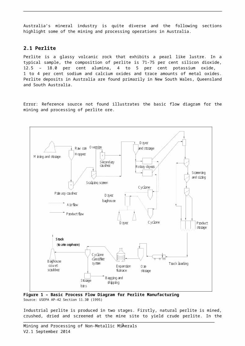
2.1 PerlitePerlite is a glassy volcanic rock that exhibits a pearl like lustre. In a typical sample, the composition of perlite is 71-75 per cent silicon dioxide, 12.5 – 18.0 per cent alumina, 4 to 5 per cent potassium oxide, 1 to 4 per cent sodium and calcium oxides and trace amounts of metal oxides. Perlite deposits in Australia are found primarily in New South Wales, Queensland and South Australia.
Error: Reference source not found illustrates the basic flow diagram for the mining and processing of perlite ore.
Mining and Processing of Non-Metallic MineralsV2.1 September 2014
2

Figure 1 – Basic Process Flow Diagram for Perlite ManufacturingSource: USEPA AP-42 Section 11.30 (1995)
Industrial perlite is produced in two stages. Firstly, natural perlite is mined, crushed, dried and screened at the mine site to yield crude perlite. In the second stage, perlite is rapidly heated for a short time to temperatures between 800oC and 1000oC to yield expanded perlite, a sterile ultra-lightweight aggregate. Bulk densities are typically 50-100 kg/m3. Typical fuel usage in the drying and heating operations (furnaces) comprises of natural gas and possibly propane.
2.2 FeldsparFeldspar minerals are a major component of igneous rocks. Feldspars are aluminosilicate minerals with varying amounts of potassium, sodium and calcium. The feldspar minerals include orthoclase (K[AlSi 3O8]), albite (Na[AlSi3O8]), anorthite (Ca[Al2Si2O8]) and celsian (Ba[Al2Si2O8]).
The alkali feldspars are used in the manufacture of porcelain and pottery fibreglass, glazes, and opalescent glass.
Feldspar and feldspathic materials are principally used as a source of alumina and alkalis in glassmaking and the ceramic industry, with sodium-rich feldspar being preferred for glassmaking and potassium-rich feldspar for ceramic manufacture. Due to the availability of cheaper, alternative materials many Australian consumers have changed to substitutes such as calcined alumina and soda ash for glassmaking.
Mining and Processing of Non-Metallic MineralsV2.1 September 2014
3
Feldspar can be extracted from high purity deposits in Australia by a simple process involving only mechanical separation and grinding. Feldspar is extracted using open cut mining and transported to a primary crusher where it is reduced to 150 millimetres. Lumps of quartz and mica are removed before transfer to a secondary crusher where the material is reduced to 40 millimetres in size. Further size reduction is achieved using a roll crusher or a pebble mill. The main commercial products are materials 1.2 millimetres and 53 micrometre in size.
Figure 2 – Process Flow Diagram for Feldspar ProcessesSource: USEPA AP-42 Section 11.27 (1995).
2.3 Phosphate rockThe term phosphate rock is used to describe sedimentary rock containing a high percentage of minerals from the apatite group – Ca5(PO4)3(F,OH,Cl).
Australia has large phosphate rock resources, (e.g. the Georgina Basin sediments in Queensland and the Northern Territory). Phosphate rock is the basic raw material for the commercial manufacture of phosphoric acid and single- and triple-super-phosphate fertiliser. Emissions of dust (including PM10) will occur during excavation, transport, crushing, screening and stockpiling of the phosphate rock.
Mining and Processing of Non-Metallic MineralsV2.1 September 2014
Particulate emissions
4
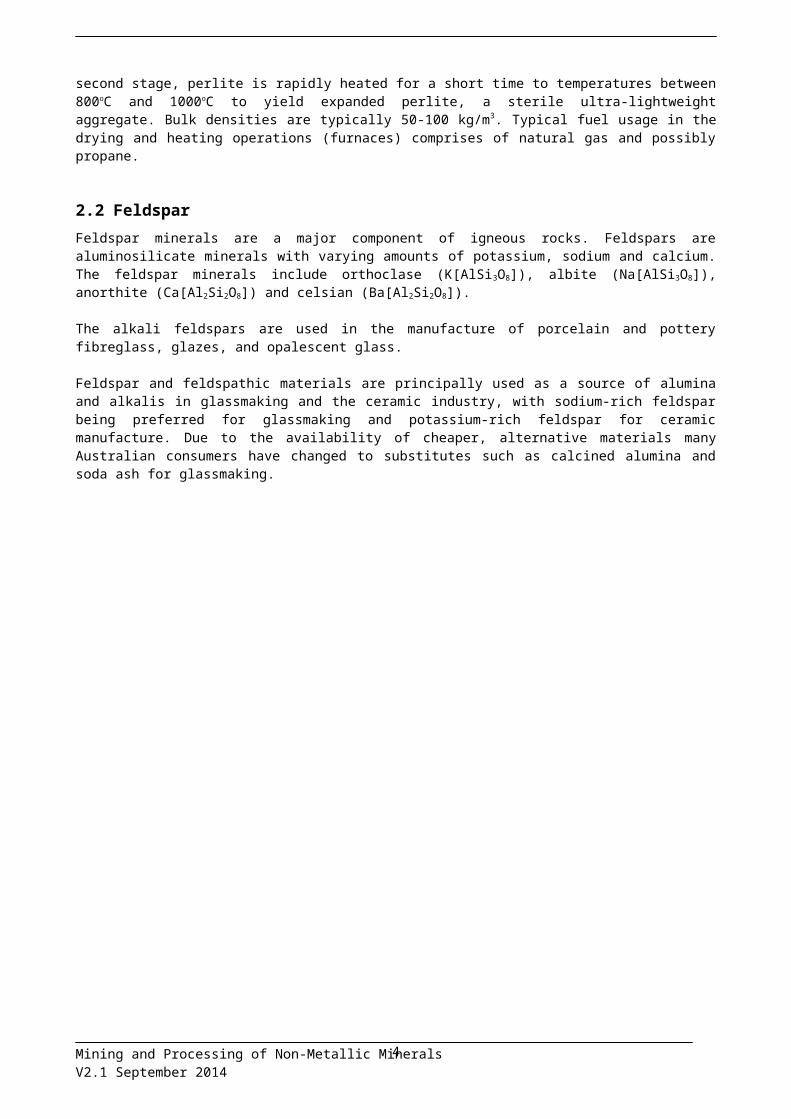
Figure 3 – Flow Diagram for Phosphate Rock ProcessingSource: USEPA AP-42 (1995).
2.4 Clay2.4.1 Clay
Clay is a natural, earthy, fine-grained material composed mostly of clay minerals with varying amounts of quartz, feldspar, micas and iron oxides. The clay minerals are crystalline hydrous aluminium silicates having the Si4O10 sheet structure. Clay minerals may also contain appreciable quantities of iron, sodium, potassium, calcium and magnesium. Clay is usually formed by the mechanical and chemical breakdown of rocks. Clay may be formed in situ or transported and deposited as sediments. Shale is a laminated sedimentary rock that is formed by the consolidation of clay, mud, or silt. Common clay and shale are composed mainly of the clay minerals, illite or chlorite, but also may contain kaolin and montmorillonite.
Most clays, except bentonite and fuller’s earth, have the property of becoming plastic and capable of being moulded when wet and then becoming hard and rock-like when heated to a suitable temperature. Clays may be classified as structural or specialist clays. Structural clays are mined and mainly used for the manufacture of ceramics, bricks, clay tiles and pipes. Other clays such as kaolinite, bentonite and fuller’s earth are mined and processed for specialised uses.
Most domestic clay is mined by open-pit methods using various types of equipment, including drag-lines, power shovels, front-end loaders, backhoes, scraper-loaders, and shale planers. In addition, some kaolin is extracted by hydraulic mining and dredging.
Clays are usually transported by truck from the mine to the processing plants, many of which are located at or near the mine. For most applications, clays are processed by mechanical methods, such as crushing, grinding, and screening, which do not appreciably alter the chemical or mineralogical properties of the material. However, because clays are used in such a wide range of applications, it is often necessary to use other mechanical and chemical processes, such as drying, calcining, bleaching, blunging, and extruding to prepare the material for use.
Primary crushing reduces material size from as much as one metre to a few centimetres in diameter and is typically accomplished using jaw or gyratory crushers. Rotating pan crushers, cone crushers, smooth roll crushers, toothed roll crushers, and hammer mills are used for secondary crushing, which further reduces particle size to 3 millimetres or less. For some applications, tertiary size reduction is necessary and is accomplished by means of ball, rod, or pebble mills, which are often combined with air separators. Screening is typically carried out by means of two or more multi-deck sloping screens that are mechanically or electro-
Mining and Processing of Non-Metallic MineralsV2.1 September 2014
5

magnetically vibrated. Pug mills are used for blunging, and rotary, fluid bed and vibrating grate dryers are used for drying clay materials. Flash, rotary or multiple hearth furnaces may be used to calcine clays.
The following paragraphs describe the various types of clay and procedures for processing them.
2.4.2 KaolinKaolin is clay composed primarily of the hydrated aluminosilicate mineral kaolinite (Al2O3.2SiO2.2H2O) with minor amounts of quartz, feldspar, mica, chlorite and other clay minerals. It is distinguished from other clays by its softness, whiteness and ease of dispersion in water. Primary kaolin deposits were formed by the alteration of in-situ minerals such as feldspar and other aluminium silicates to kaolinite. Secondary deposits were laid down as sediments, usually in fresh water, far from the place of origin. Various types of secondary kaolins may be termed ball clays, fireclays or flint clays depending on their properties or use. Kaolin has applications as a filler and extender in paper, paints and plastics. Ball clay is a plastic white-firing clay that is composed primarily of kaolinite and is used mainly to make ceramic pottery, tiles, insulators and refractories. Fire clays are composed primarily of kaolinite, but may also contain several other materials including diaspore, burley, burley-flint, ball clay, bauxitic clay and shale. Because of their ability to withstand temperatures of 1500°C or higher, fire clays generally are used for refractories or to raise vitrification temperatures in heavy clay products. Flint clay, a hard kaolinitic rock, is used mainly in refractories.
Flow diagrams for dry and wet processing of kaolin are shown in Figure 4 and Figure 5 respectively. The dry process is simpler and produces a lower quality product than the wet process. Dry-processed kaolin is used mainly in the rubber industry, and to a lesser extent, for paper filling and to produce fibreglass and sanitary ware. Wet-processed kaolin is used extensively in the paper manufacturing industry.
In the dry process, the raw material is crushed to the desired size, dried in rotary dryers, pulverized and air-floated to remove most of the coarse grit.
Figure 4 – Process Flow Diagram for Kaolin Mining and Dry ProcessingSource: USEPA AP-42 (1995).
Mining and Processing of Non-Metallic MineralsV2.1 September 2014
6

Wet processing of kaolin begins with blunging to produce a slurry which is then fractionated into coarse and fine fractions using centrifuges, hydro-cyclones, or hydro-separators. At this step in the process, various chemical methods, such as bleaching, and physical and magnetic methods, may be used to refine the material. Chemical processing includes leaching with sulfuric acid, followed by the addition of a strong reducing agent such as hydrosulfite. Before drying, the slurry is filtered and de-watered by means of a filter press, centrifuge, rotary vacuum filter, or tube filter. The filtered de-watered slurry material may be shipped or further processed by drying in apron, rotary, or spray dryers. Following the drying step, the kaolin may be calcined, usually in a multiple hearth furnace, for use as filler or refractory material.
Mining and Processing of Non-Metallic MineralsV2.1 September 2014
7

Figure 5 – Process Flow Diagram for Wet Process Kaolin for High Grade ProductsSource: USEPA AP-42 Section 11.25 (1995)
Mining and Processing of Non-Metallic MineralsV2.1 September 2014
8

2.4.3 Ball clay Ball clay, which typically has a moisture content of approximately 28 per cent, is first stored in drying sheds until the moisture content decreases to 20 to 24 per cent. The clay then is shredded in a disintegrator into small pieces 1.3 to 2.5 centimetres thick. The shredded material is either dried or ground in a hammer mill. Material exiting the hammer mill is mixed with water, and bulk loaded as a slurry for shipping. Figure depicts the process flow for ball clay processing. Indirect rotary or vibrating grate dryers are used to dry ball clay. Combustion gases from the firebox pass through an air-to-air heat exchanger to heat the drying air to a temperature of approximately 300°C. The clay is dried to a moisture content of 8 to 10 per cent. Following drying, the material is ground in a roller mill and shipped. The ground ball clay may also be mixed with water as a slurry for bulk shipping.
2.4.4 Fire clayMined fire clay is first transported to the processing plant and stockpiled. In some cases, the crude clay is weathered for 6 to 12 months, depending on the type of fire clay. Weathering breaks the material up, resulting in smaller particles and improved plasticity. The material is then crushed and ground. At this stage in the process, the clay has a moisture content of 10 to 15 per cent. For certain applications, the clay is dried in mechanical dryers to reduce the moisture content of the material to 7 per cent or less. Rotary and vibrating grate dryers fired with natural gas or fuel oil are typically used for drying fire clay. To increase the refractoriness of the material, fire clay is often calcined. Calcining eliminates moisture and organic material and causes a chemical reaction between the alumina and silica in the clay, producing a material (mullite) that is harder, denser, and more easily crushed than uncalcined fire clay. After the clay is dried and/or calcined, the material is crushed, ground, and screened. After screening, the processed fire clay may be blended with other materials, such as organic binders, before being formed in the desired shapes and fired.
Mining and Processing of Non-Metallic MineralsV2.1 September 2014
9

Figure 6 – Process Flow Diagram for Ball Clay ProcessingSource: USEPA AP-42 Figure 11.25-3 (1995).
Mining and Processing of Non-Metallic MineralsV2.1 September 2014
10

Figure 7 – Process Flow Diagram for Fire Clay ProcessingSource: USEPA, AP-42, Section 11, (1995)
Mining and Processing of Non-Metallic MineralsV2.1 September 2014
11
2.4.5 BentoniteBentonite consists predominantly of the swelling clay montmorillonite, a loosely bound sheet silicate with exchangeable sodium, calcium, and magnesium cations. The most useful properties of bentonite include its ability to exchange cations, its swelling and hydration capacity, its ability to act as a binder and its impermeability.
Applications are extensive as a result of the clay’s different properties. Uses include drilling muds, civil engineering applications, foundry moulds, animal feed, pet litter, sealants, horticulture, wine making, absorbents, catalysts, binders, furnace linings, ceramics, pesticides, paints, purifying and de-colourising fats and oils, medical and pharmaceutical products. Specialised grades of bentonite are used in a wide range of industrial applications for domestic and export markets. Bentonite is a major component in foundry sand and drilling muds and it is widely used in the pelletisation of stockfeeds. Particular types are used to seal dams and for other civil engineering applications and as a moisture absorbent in pet litter. Acid activated bentonite is also used in refining oils, fats and solvents. Particular types have a high absorbency for gaseous, liquid and solid industrial wastes, including heavy metal contaminants in solution and for oil spillages both on land and water. Bentonite is being used increasingly for environmental applications.
Figure 8 shows a flow diagram for bentonite processing. Mined bentonite first is transported to the processing plant and stockpiled. If the raw clay has a relatively high moisture content (30 to 35 per cent), the stockpiled material may be ploughed to facilitate air drying to a moisture content of 16 to 18 per cent. Stockpiled bentonite may also be blended with other grades of bentonite to produce a uniform material. The material is then passed through a grizzly and crusher to reduce the clay pieces to less than 2.5 centimetres in size. Next, the crushed bentonite is dried in rotary or fluid bed dryers fired with natural gas, oil, or coal to reduce the moisture content to 7 to 8 per cent. The temperatures in bentonite dryers generally range from 900°C at the inlet to 100 to 200°C at the outlet. The dried material is then ground by means of roller or hammer mills. At some facilities that produce specialised bentonite products, the material is passed through an air classifier after being ground. Soda ash also may be added to the processed material to improve the swelling properties of the clay.
Figure 8 – Process Flow Diagram for Bentonite ProcessingSource: USEPA AP-42 Section 11.25 (1995)
Mining and Processing of Non-Metallic MineralsV2.1 September 2014
12

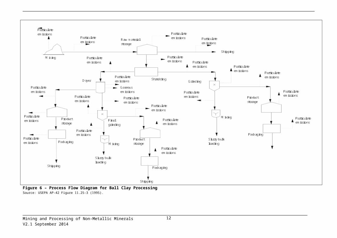
2.4.6 Fuller’s earthFuller’s earth consists of montmorillonite and other hydrous aluminium silicate minerals. It is a non-plastic clay high in magnesium and has specialised decolourising and purifying properties. Fuller’s earth has similar uses to bentonite as an absorbent of pet waste, oil, and grease.
Figure 9 presents a process flow diagram for fuller’s earth. After being mined, fuller’s earth is transported to the processing plant, crushed, ground, and stockpiled. Before drying, fuller’s earth is fed into secondary grinders to reduce further the size of the material. At some plants, the crushed material is fed into a pug mill, mixed with water, and extruded to improve the properties needed for certain end products. The material is then dried in rotary or fluid bed dryers fired with natural gas or fuel oil. Drying reduces the initial moisture content, from 40 to 50 per cent, to 10 per cent or below. The temperatures in fuller’s earth dryers depend on the end use of the product. For colloidal grades of fuller’s earth, drying temperatures of approximately 150°C are used, and for absorbent grades, drying temperatures of 650°C are common. In some plants, fuller’s earth is calcined rather than dried. In these cases, an operating temperature of approximately 675°C is used. The dried or calcined material is then ground by roller or hammer mills and screened.
Figure 9 – Process Flow Diagram for Fuller’s Earth ProcessingSource: USEPA AP-42 Section 11.25 (1995)
Mining and Processing of Non-Metallic MineralsV2.1 September 2014
13

2.4.7 Common clay and shale Common clay is defined as a plastic clay or clay-like material with a vitrification point below 1100°C. Shale is a laminated sedimentary rock that is formed by the consolidation of clay, mud, or silt. Common clay and shale are composed mainly of illite or chlorite, but may also contain kaolin and montmorillonite.
Figure 10 depicts common clay and shale processing. Common clay and shale generally are mined, processed, formed, and fired at the same time to produce the end product. Processing generally begins with primary crushing and stockpiling. The material is then ground and screened. Oversize material may be further ground to produce particles of the desired size. For some applications, common clay and shale are dried to reduce the moisture content to desired levels. Depending on the type of end product further processing may include blunging or mixing with water in a pug mill, extruding and firing in a kiln.
Mining and Processing of Non-Metallic MineralsV2.1 September 2014
14

Figure 10 – Process Flow Diagram for Common Clay and Shale ProcessingSource: USEPA AP-42 Section 11.25 (1995)
Mining and Processing of Non-Metallic MineralsV2.1 September 2014
15
2.5 VermiculiteVermiculite is a hydrous magnesium silicate. The mineral has a sheet structure resembling that of talc but with water molecules present in some of the sheets. When subjected to heat, vermiculite has the unusual property of exfoliating or expanding, due to the inter-laminar generation of steam.
Vermiculite is used for the production of insulating materials lightweight cements and plasters, for refractory purposes, a filler for paints, paper and rubber, and as an absorbent for nitro-glycerine
Vermiculite ore is mined using open-pit methods. Beneficiation includes screening, flotation, drying in rotary or fluid bed dryers, and expansion by exposure to high heat. Vermiculite is dried and sized at the mine site prior to exfoliation.
Figure 11 is a flow diagram for vermiculite processing. Crude ore from open-pit mines is brought to the mill by truck and is loaded onto outdoor stockpiles. Primary processing consists of screening the raw material to remove the waste rock greater than 1.6 centimetres and returning the raw ore to stockpiles. Blending is accomplished as material is removed from stockpiles and conveyed to the mill feed bin. The blended ore is fed to the mill, where it is separated into fractions by wet screening and then concentrated by gravity. All concentrates are collected, de-watered, and dried in either a fluidised bed or rotary dryer. Drying reduces the moisture content of the vermiculite concentrate from approximately 15 to 20 per cent to approximately 2 to 6 per cent. At most facilities, the dryer products are transported by bucket elevators to vibrating screens, where the material is classified. The dryer exhaust is generally ducted to a cyclone for recovering the finer grades of vermiculite concentrate. The classified concentrate is then stored in bins or silos for later shipment or exfoliation.
The rotary dryer is the more common dryer type used in the industry, although fluidised bed dryers also are used. Drying temperatures are 120C to 480C, and fuel oil is the most commonly used fuel. Natural gas and propane also are used to fuel dryers.
After being transported to the exfoliation plant, the vermiculite concentrate is stored. The ore concentrate is then conveyed by bucket elevator or other means and is dropped continuously through a gas- or oil-fired vertical furnace. Exfoliation occurs after a residence time of less than eight seconds in the furnace, and immediate removal of the expanded material from the furnace prevents damage to the structure of the vermiculite particle. Flame temperatures of more than 540C are used for exfoliation. Proper exfoliation requires both a high rate of heat transfer and a rapid generation of steam within the vermiculite particles. The expanded product falls through the furnace and is air-conveyed to a classifier system, which collects the vermiculite product and removes excessive fines. The furnace exhaust is generally ducted through a product recovery cyclone, followed by an emission control device. At some facilities, the exfoliated material is ground in a pulveriser prior to being classified. Finally, the material is packaged and stored for shipment.
Mining and Processing of Non-Metallic MineralsV2.1 September 2014
17

Figure 11 – Process Flow Diagram for Vermiculite ProcessingSource: USEPA AP-42 Section 11.28 (1995)
Mining and Processing of Non-Metallic MineralsV2.1 September 2014
18

2.6 DiatomiteDiatomite is a chalky, sedimentary rock consisting of the skeletons of siliceous organisms, algae and diatoms. The skeletons are essentially amorphous hydrated or opaline silica occasionally with some alumina. Diatomite is used for polishing powder, filtering medium and in cement glazes pigments.
Most diatomite deposits are found at or near the earth's surface and can be mined by open pit methods or quarrying normally using some combination of bulldozers, scraper-carriers, power shovels, and trucks to remove overburden and the crude material. In most cases, fragmentation by drilling and blasting is not necessary. The crude diatomite is loaded on trucks and transported to the mill or to stockpiles.
The processing of uncalcined or natural-grade diatomite consists of crushing and drying. Crude diatomite commonly contains as much as 40 per cent moisture, in many cases over 60 per cent. Primary crushing to aggregate size (normally done by a hammer-mill) is followed by simultaneous milling and drying, in which suspended particles of diatomite are carried in a stream of hot gases. Flash and rotary dryers are used to dry the material to a powder of approximately 15 per cent moisture. Typical flash dryer operating temperatures range from 70C to 430C. The suspended particles exiting the dryer pass through a series of fans, cyclones, and separators to a baghouse. These sequential operations separate the powder into various sizes, remove waste impurities, and expel the absorbed water. These natural-milled diatomite products are then bagged or handled in bulk without additional processing.
For filtration uses, natural grade diatomite is calcined by heat treatment in gas- or fuel oil-fired rotary calciners, with or without a fluxing agent. Typical calciner operating temperatures range from 650 C to 1200C. For straight-calcined grades, the powder is heated in large rotary calciners to the point of incipient fusion, and thus, in the strict technical sense, the process is one of sintering rather than calcining. The material exiting the kiln is then further milled and classified. Straight calcining is used for adjusting the particle-size distribution for use as a medium flow-rate filter aid. The product of straight calcining has a pink colour from the oxidation of iron in the raw material, which is more intense with increasing iron oxide content.
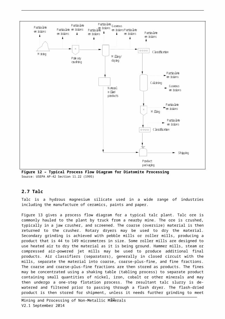
Further particle size adjustment is brought about by the addition of a flux, usually soda ash, before the calcining step. Added fluxing agent sinters the diatomite particles and increases the particle size, thereby allowing increased flow rate during liquid filtration. The resulting products are called "flux-calcined". Flux-calcining produces a white product, believed to be coloured by the conversion of iron to complex sodium-aluminium-iron silicates rather than to the oxide. Further milling and classifying follow calcining. Particulate matter is emitted from crushing, drying, calcining, classifying, materials handling, and transfer operations. Emissions from dryers and calciners include products of combustion, such as carbon oxides, nitrogen oxides, sulfur oxides and PM10. Figure 12 shows a typical process flow diagram for diatomite processing.
Mining and Processing of Non-Metallic MineralsV2.1 September 2014
19

Figure 12 – Typical Process Flow Diagram for Diatomite ProcessingSource: USEPA AP-42 Section 11.22 (1995)
2.7 TalcTalc is a hydrous magnesium silicate used in a wide range of industries including the manufacture of ceramics, paints and paper.
Figure 13 gives a process flow diagram for a typical talc plant. Talc ore is commonly hauled to the plant by truck from a nearby mine. The ore is crushed, typically in a jaw crusher, and screened. The coarse (oversize) material is then returned to the crusher. Rotary dryers may be used to dry the material. Secondary grinding is achieved with pebble mills or roller mills, producing a product that is 44 to 149 micrometres in size. Some roller mills are designed to use heated air to dry the material as it is being ground. Hammer mills, steam or compressed air-powered jet mills may be used to produce additional final products. Air classifiers (separators), generally in closed circuit with the mills, separate the material into coarse, coarse-plus-fine, and fine fractions. The coarse and coarse-plus-fine fractions are then stored as products. The fines may be concentrated using a shaking table (tabling process) to separate product containing small quantities of nickel, iron, cobalt or other minerals and may then undergo a one-step flotation process. The resultant talc slurry is de-watered and filtered prior to passing through a flash dryer. The flash-dried product is then stored for shipment, unless it needs further grinding to meet customer specifications. The classified material may also be pelletised prior to packaging for specific applications. In the pelletising step, processed talc is mixed with water to form a paste and is extruded as pellets.
Talc deposits containing organic impurities must be calcined prior to additional processing to yield a product with uniform chemical and physical properties. Prior to calcining, the mined ore passes through a crusher and is ground to a specified screen size. After calcining in a rotary kiln, the material passes through a rotary cooler. The cooled calcined talc (0 per cent free water) is then either stored for shipment or further
Mining and Processing of Non-Metallic MineralsV2.1 September 2014
20

processed. Calcined talc may be mixed with dried talc from other product lines and passed through a roller mill prior to bulk shipping.
The primary pollutant of concern in talc processing is particulate matter. Particulate matter is emitted from drilling, blasting, crushing, screening, grinding, drying, classifying, materials handling, transfer operations, packaging and storage.
Figure 13 – Process Flow Diagram for Talc ProcessingSource: USEPA AP-42 Section 11.26 (1995)
Mining and Processing of Non-Metallic MineralsV2.1 September 2014
21

2.8 LimestoneThe term limestone is used to describe sedimentary rocks containing calcium carbonate, which is present as the minerals calcite and aragonite. Limestone may contain varying amounts of dolomite (calcium-magnesium carbonate) as well as silica and alumina. Limestone is mainly used for manufacturing Portland cement and lime, as a flux in steel making, in copper and lead smelting, in glass manufacturing, alumina refining and in agriculture. Most consumers of limestone rely on being able to obtain raw material that meets certain specifications in terms of physical properties (crystal size) or chemical content. Special grades of high-quality white calcium oxide are used for paper coating. Calcium oxide (quick lime) is derived from limestone by calcining to expel carbon dioxide. Cement clinker is produced by burning a slurry of limestone, clay, sand, iron stone and water in a kiln. The clinker is then ground with gypsum to make cement.
Mining and processing of limestone typically involves removal of overburden, blasting, shovelling and transport by truck to the crushing and blending plant.
2.9 MagnesiteMagnesite is a mineral composed of magnesium carbonate, (MgCO3). After removal of over-burden, magnesite is extracted by open-pit mining and crushed, screened, washed and sorted at the mine site. Raw magnesite is used in paints, and as a filler in plastics and paper. It is used for surface coatings, landscaping, ceramics, and as a fire retardant. It can also be mixed with limestone to form a synthetic dolomite for use an agricultural fertiliser.
Magnesite is the most important source mineral for producing magnesia (MgO). Raw magnesia is converted to calcined magnesia (MgO) by heating to 700C - 1000C. Calcined (or caustic magnesia) is used in the manufacture of paints, paper, plastics, rubber, oil, pharmaceutical products, fertiliser and animal feed. It is also used in building materials, as a fire retardant, and for acid neutralisation.
With further processing, calcined magnesia is made into pellets and heated to 1500 C - 2000C in shaft kilns forming dead-burned magnesia. Dead-burned magnesia, also known as sintered magnesia or clinker, is used to make refractory bricks to line steel making furnaces. When calcined magnesia is heated to 2750C - 3000C in electric furnaces, electro-fused magnesia is produced. Electro-fused magnesia has higher strength, abrasion resistance, and chemical inertness than dead-burned magnesia. It is used for premium grade refractory bricks, electrical substrates, high temperature insulators, and ceramics. Electro-fused magnesia is also used for special refractory applications in the nuclear and space industries.
Magnesite can also be used to produce magnesium metal by the electrolytic reduction of magnesium chloride, or by the reduction of magnesium compounds with ferrosilicon.
Particulates and combustion gases from machinery used in the mining process are the major air pollutants emitted from the mining and beneficiation of magnesite. Combustion gases from the heating processes become an important consideration in the production of calcined magnesia, dead-burned magnesia and electro-fused magnesia but these processes are not usually carried out at the mine site.
2.10 Silica sandThe mineral silica (SiO2) occurs in abundance as sand, sandstone, quartz, quartzite, and quartz gravel.
In Australia, high-grade industrial silica is mined from surface deposits (dunes). High quality silica is used for the manufacture of glass, refractories, cement, foundry sand, metallurgical flux, for silicon metal and other silicon containing products.
Sand is scooped up from surface deposits, transferred by conveyer to an up-grading plant where it is sieved wet, the water is drained using a drier belt and the product is stock-piled and then transferred to ships. The sand deposits at Cape Flattery contain less than 0.01 per cent of fine particles less than 50 micrometres in diameter and the processed product is 99.8 per cent pure silica.
Mining and Processing of Non-Metallic MineralsV2.1 September 2014
22
2.11 Sand and gravel2.11.1 Sand and gravel processing
Sand and gravel are siliceous and calcareous products of the weathering of rock and stone. Deposits of sand and gravel are generally found in near-surface alluvial deposits and in subterranean and subaqueous beds. Construction sand and gravel are typically mined in a moist or wet condition by open pit excavation or by dredging. Open pit excavation is carried out with power shovels, drag lines, front-end loaders, and bucket wheel excavators. Mining by dredging involves mounting the equipment on boats or barges and removing the sand and gravel from the bottom of a body of water by suction or bucket type dredges. After mining, the materials are transported to the processing plant by suction pump, earthmover, barge, truck, belt conveyers or other means.
The processing of sand and gravel for a specific market involves the use of different combinations of washers, screens, and classifiers to segregate particle sizes; crushers to reduce oversized material; and storage and loading facilities.
2.11.2 Industrial sand and gravelIndustrial sand and gravel typically are mined from open pits of naturally occurring quartz rich sand and sandstone. Mining methods depend primarily on the degree of cementation of the rock. After mining, the rock is crushed in several stages. Gyratory crushers, jaw crushers, roll crushers, and impact mills are used for primary and secondary crushing. The size of the material is further reduced to 50 micrometres or smaller by grinding, using smooth rolls, media mills, autogenous mills, hammer mills, or jet mills. The ground material then is classified by wet screening, dry screening, or air classification. Impurities may be removed by washing or froth flotation. The final product is dried, classified and stored.
Emissions from the production of sand and gravel consist primarily of particulates, which are emitted by many operations at sand and gravel processing plants, such as conveying, screening, crushing, and storing operations. Generally, the materials are wet or moist when handled, and process emissions are often negligible. A substantial portion of the emissions may consist of heavy particles that settle out within the plant.
Emissions from dryers include PM2.5 and PM10, as well as typical combustion products including CO and NOx. In addition, dryers may be sources of VOCs or sulfur oxides (SO2) emissions, depending on the type of fuel used to fire the dryer.
2.12 Crushed stone processingMajor rock types processed by the rock and crushed stone industry include limestone, granite, dolomite, sandstone, quartz, and quartzite. Rock and crushed stone products are loosened by drilling and blasting, and then loaded by power shovel or front-end loader into large haul trucks that transport the material to the processing operations. Techniques used for extraction vary with the nature and location of the deposit.
Processing operations may include crushing, screening, size classification, material handling, and storage operations. All of these processes can be significant sources of particulate emissions if uncontrolled. A substantial portion of these emissions consists of heavy particles that may settle out within the plant. Typical size classifications that occur as a result of crushing and screening processes are:
Primary crushing 7.5 to 30 cmSecondary crushing 2.5 to 10 cmTertiary crushing 0.5 to 2.5 cmFines screening < 0.5 cmFines crushing < 0.5 cm
Crushed stone emission sources may be categorised as either process sources or fugitive dust sources. Process sources include those for which emissions are amenable to capture and subsequent control. Fugitive dust sources generally involve the re-entrainment of settled dust by wind or machine movement. Emissions from process sources should be considered fugitive unless the sources are vented to a baghouse or are contained in an enclosure with a forced-air vent or stack. Factors affecting emissions from either source category include the stone size distribution and surface moisture content of the stone processed; the process throughput rate; the type of equipment and operating practices used; and topographical and climatic factors. Fugitive emissions typically increase at higher wind speeds. Both fugitive and process emissions may increase with lower moisture content of the material processed.
Mining and Processing of Non-Metallic MineralsV2.1 September 2014
23
A variety of material, equipment, and operating factors can influence emissions from crushing. These factors include:
(1) stone type; (2) feed size and distribution;(3) moisture content;(4) throughput rate; (5) crusher type; (6) size reduction ratio; and (7) fines content.
2.13 GemstonesGemstones mined in Australia include opal, sapphire, diamond, chrysoprase, garnet and zircon.
Sapphire is a variety of the mineral corundum, which consists of aluminium oxide. The presence of small amounts of oxides of iron, titanium and chromium can impart a wide range of colours to the mineral. Sapphire occurs in alluvial deposits. Mining of sapphires varies from simple hand mining of surface and shallow wash through digging shafts in deeper ground to large-scale open cuts operations involving heavy machinery.
Opal is a hydrated form of silica in which water is chemically bonded. There are two main forms of opal: precious opal and common opal. Precious opal exhibits the characteristic play of spectral colours and is comparatively rare. Common opal shows no play of colours. It may be colourless or coloured and can be transparent to opaque. Opal is mined from underground shafts but the larger mines are open-cut operations. Ironstone boulders are carefully removed from the ground for processing.
Garnet comprises a group of complex aluminium silicate minerals, some varieties are used as a gemstone. Garnet is being increasingly used as a high quality abrasive for sandpaper, in sand blasting, on non-skid surfaces and as a filtration medium. Mining involves drilling and blasting. The material is reduced in size using two-stage crushing and rolling to produce 3 millimetre size material. The material is then dried. Magnetic separation gives a 99 per cent pure product.
2.14 GypsumThe mineral gypsum is composed of calcium sulfate CaSO4.2H2O. In its natural state, gypsum is generally associated with impurities such as sand, clay and limestone. South Australia, with deposits located close to ports, is the major producer of gypsum. Gypsum is used as a soil conditioner, while calcined gypsum is used widely for plaster sheets and finishings in the building industry.
The gypsum that occurs as sedimentary deposits together with salt is excavated and pushed up into stockpiles. After natural rainfall has leached the salt from the stockpiles, the gypsum is crushed to size and shipped to plasterboard manufacturing plants located in the major population centres.
2.15 ZeoliteZeolite is a calcium aluminium silicate mineral derived from volcanic ash, which has been highly compressed by the weight of sedimentary layers and coal deposits. Deposits of zeolite may be lifted to the surface by earthquake activity over geological time scales of hundreds of millions of years. Zeolite is used as a cation exchanger, an absorbent for odours, a flocculant for wastewater and a soil conditioner. Zeolite is extracted from surface deposits by drilling and blasting. The product is crushed to various sizes and packaged in 20 kilograms and one tonne quantities. A powdered form (50 micrometres) which may be transported by tanker is also produced using a ball mill.
2.16 BariteThe mineral barite (barytes) is a soft dense mineral consisting of barium sulfate. It is used primarily as a weighting agent in oil drilling muds, as a filler and extender in paint and plastics, as a flux in glassmaking and as a source material for barium chemicals.
Mining and Processing of Non-Metallic MineralsV2.1 September 2014
24

2.17 Dimension stoneDimension stone is natural stone that has been cut or shaped to a specific size for a particular building or decorative application. The term encompasses a large variety of rock types; the most popular of which are granite, sandstone, marble and slate.
Dimension stone is usually obtained from surface quarries. In many cases, overburden is removed using bulldozers or other earth moving equipment. The stone is then cut into blocks by drilling, cutting or blasting. Large blocks are then cut into sheets using gang saws. These sheets are then trimmed to the required size and shape. Depending on the application, the stone is then given a surface finish, which may range from a rough non-slip texture to a polished mirror surface.
2.18 Serpentine and rhyolite Serpentine is a rock composed largely of serpentine, a magnesium-rich silicate mineral associated with ultrabasic igneous rocks. Its prime use is as a flux for steel making.
Rhyolite is a fine-grained volcanic rock consisting mainly of quartz and feldspar minerals. It is typically used as a fluxing agent in ceramic manufacture.
Mining and Processing of Non-Metallic MineralsV2.1 September 2014
25
3 Estimating emissions from mining and processing of non-metallic minerals
Before you start estimating your facility’s emissions it may be helpful to draw a process flow diagram of your facility’s operations. This will help you to identify all the possible emission points of NPI substances such as output and emission streams. After you have identified all the emission sources of NPI substances you can start to estimate emissions.
Five methods for estimating emissions are available:- Mass balance- Fuel analysis or engineering calculations- Sampling or direct measurement- Emission factors- Approved alternative*
*Your state or territory environment agency must give you written approval to use techniques that are not specified in the industry reporting materials
Further information on these emission estimation techniques is available in the NPI Guide.
3.1 Emissions to airProcess emissions can be either Point Source or Fugitive emissions, depending on the process and ventilation system.
Point source emissions are emissions which flow into a vent or stack and are emitted through a single point source into the atmosphere. Point source emissions at a non-metallic mineral mining facility may occur from:
emissions from fuel combustion processes from stationary equipment (e.g. stationary engines for power generation)
non-metallic mineral processing
Fugitive emissions are not released via a vent or stack. Fugitive emissions at a non-metallic mineral mining facility may occur from:
windblown dust materials handling fuel storage fuel combustion (e.g. explosives and vehicle exhaust) non-metallic mineral processing
3.1.1 Power generationFor facilities with on-site power generation, emission estimation techniques can be found in the EET Manual for Fossil Fuel Electric Power Generation. For sites that use diesel engines, emission estimation techniques can be found in the EET Manual for Combustion Engines.
3.1.2 Vehicle exhaustThe latest version of the EET Manual for Combustion Engines provides emission estimation techniques associated with fuel combustion in vehicles.
3.1.3 Dust emissions The major fugitive emission from non-metallic mineral mining is dust, of which PM10 is reportable if triggered by on-site fuel burning (see the NPI Guide for further information). Emissions of metals will also need to be reported if fuel combustion exceeds defined thresholds, or if NPI-listed metals are present in the mined ore, or waste, in quantities that exceed the Category 1 threshold. If Category 1 is exceeded, total suspended particulate (TSP) emissions will need to be calculated (in addition to emissions of PM10) to determine metal emissions.
Fugitive dust emissions can be generated by a number of sources including the movement of vehicles, blasting, materials handling and wind erosion of exposed areas. In most cases fugitive air emissions can be estimated using emission factors combined with site-specific information such as the silt and moisture
Mining and Processing of Non-Metallic MineralsV2.1 September 2014
26

content of material being handled. Emission estimation techniques for dust sources can be found in the EET Manual for Mining and the EET Manual for Fugitive Emissions.
3.1.4 Fuel storage tanks Fugitive emissions from storage tanks include evaporative losses from filling and transfer operations, as well as standing losses. For the purposes of fugitive emissions estimation, storage tanks are:
fixed roof tanks floating roof tanks variable vapour space tanks.
The latest version of the EET Manual for Fuel and Organic Liquid Storage provides guidance on the estimation of emissions from facilities storing liquid fuels and organic liquids. Emission factors are listed for each tank type, by climatic zone and fuel type, in the Appendix of that manual.
The EET Manual for Fuel and Organic Liquid Storage also provides reference to the US EPA TANKS 4.09D software to estimate emissions from fuel and organic liquid storage, which can be used to produce more accurate estimates of emissions from fuel and organic liquid storage. A user manual for TANKS 4.09D is provided in an Appendix of the Manual.
TANKS 4.09D requires information such as the physical characteristics of the storage tanks, typical atmospheric conditions (such as wind speeds and temperatures), the contents of the tank, and throughput.
Emissions of volatile solvents can be estimated on the basis of annual usage, assuming that all solvents are volatilised. Any vapour recovery system should be accounted for in controls.
3.1.5 Explosive detonationFuel used during blasting activities needs to be considered when assessing if 1 tonne or more fuel or waste has been burnt in an hour during the reporting period. The latest version of the EET Manual for Explosives detonation and firing ranges provides guidance on the estimation of combustion emissions explosive detonation.
3.1.6 Processing of non-metallic mineralsThe Tables in this section have been extracted from US EPA (1998), AP-42, Chapter 11. They present emission factors for some aspects of the processing of various non-metallic minerals.
The Tables give emissions factors for filterable PM and condensable PM. These terms originate from the USEPA emissions test method 5 for emissions of particulate matter from stacks. The terms refer to particulate matter collected in the heated and cooled parts respectively, of the sampling train. The factors do not allow emissions of the PM10 fraction to be calculated directly unless data on particle size distribution is also available. US EPA (1988) provides particle size distribution data for filterable PM for phosphate rock dryers and calciners and the processing of bentonite and fire clay. This information is included in Table 6, Table 10 and Table 12 of this manual. USEPA AP-42, Appendix B2 (1995) provides information on generic particle size distributions and typical control efficiencies for various particle control devices. This information may be applied to estimate PM10 emissions from some of the non-metallic minerals processes. Some of the tables include emission factors for combustion gases for drying and calcining processes.
Mining and Processing of Non-Metallic MineralsV2.1 September 2014
27
PerliteTable 1 – Emission Factors for Perlite Processinga
Process
Filterable PMb
kg/tPerlite
Expanded
Emission Factor Rating
Expansion furnace NDExpansion furnace with wet cyclone 1.1 DExpansion furnace with cyclone and baghouse 0.15 DDryer NDDryer with baghouse 0.64 DDryer with cyclones and baghouses 0.139 D
Source: USEPA AP-42 Table 11.30-1 (1995)ND No Dataa All emission factors represent controlled emissions.b Filterable PM is that PM collected on or prior to the filter of an USEPA Method 5 (or equivalent) sampling train.
FeldsparTable 2 – Emission Factors for Feldspar Processing – Filterable Particulate Matter
ProcessFilterable Particulate
kg/tFeldspar
Dried
EmissionFactorRating
Dryer with scrubber and demisters 0.60 DDryer with mechanical collector and scrubber 0.041 D
Source: USEPA AP-42 Table 11.27-1 (1995).
Phosphate RockTable 3 – Emission Factors for Phosphate Rock Processing – Combustion Gases a
Process S02 CO Emission Factor Ratingkg/t of Total
Feedkg/t of Total
FeedDryer ND 0.17 DCalciner with scrubber 0.0034 ND D
Source: USEPA AP-42 Table 11.21-2 (1995)ND No Dataa Factors represent uncontrolled emissions unless otherwise noted.
Mining and Processing of Non-Metallic MineralsV2.1 September 2014
28

Table 4 – Emission Factors for Phosphate Rock Processinga
Filterable PMb Condensable PMc
PM PM10 Inorganic OrganicProcess kg/t of
Total FeedEmission
Factor Rating
kg/t of Total Feed
Emission Factor Rating
kg/t of Total Feed
Emission Factor Rating
kg/t of Total Feed
Emission Factor Rating
Dryer 2.9 D 2.4 E ND NDDryer with scrubber
0.035 D ND 0.015 D ND
Dryer with ESP
0.016 D ND 0.004 D ND
Grinder 0.8 C ND ND NDGrinder with fabric filter
0.0022 D ND 0.0011 D ND
Calciner 7.7 D 7.4 E ND NDCalciner with scrubber
0.10 C ND 0.0079 C 0.044 D
Transfer and storage
2 E ND ND ND
Source: USEPA AP-42 Table 11.21-3 (1995)ND No Dataa Factors represent uncontrolled emissions unless otherwise stated.b Filterable PM is that PM collected on or prior to the filter of an USEPA Method 5 (or equivalent) sampling train. PM10 values are based on cascade impaction particle size distribution.c Condensable PM is that PM collected in the impinger portion of a PM sampling train.
Mining and Processing of Non-Metallic MineralsV2.1 September 2014
29

Table 5 – Emission Factors for Phosphate Rock Processing – Fluoride a
ProcessFluoride, H20-Soluble Fluoride, Total
kg/t of Total Feed
Emission Factor Rating
kg/t of Total Feed
Emission Factor Rating
Dryer 0.00085 D 0.037 DDryer with scrubber
0.00048 D 0.0048 D
Grinder ND NDGrinder with fabric filter
ND ND
Calciner with scrubber
ND 0.00081 D
Source: USEPA AP-42, Section 11.21, Table 11.21-6 (1995)ND No Dataa Factors represent uncontrolled emission unless otherwise noted.
Table 6 – Particle Size Distribution of Filterable Particulate Emissions from Phosphate Rock – Dryers and Calciners
Diameter, m Per cent Less Than SizeDryers Calciners
105210.80.5
82 9660 8127 5211 26
7 103 5
Source: USEPA AP-42, Section 11.21, Table 11.21-5 (1995)Emission Factor Rating: E
KaolinTable 7 – Emission Factors for Kaolin Processinga
Source Filterable PMb Filterable PM10c Emission Factor
RatingSpray dryer with fabric filter 0.12 ND DApron dryer 0.62 ND DMultiple hearth furnace 17 8.2 DMultiple hearth furnace with venturi scrubber
0.12 ND D
Flash calciner 550 280 DFlash calciner with fabric filter 0.028 0.023 D
Source: USEPA AP-42, Section 11.25, Table 11.25-2 (1995)ND No Dataa Factors are kg/t produced. Emissions are uncontrolled unless noted.b Filterable PM is that PM collected on or before the filter of an USEPA Method 5 (or equivalent) sampling train.c Based on filterable PM emission factor and particle size data.
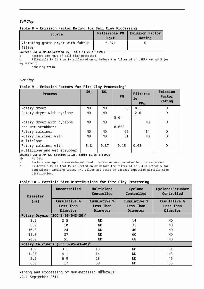
Ball ClayTable 8 – Emission Factor Rating for Ball Clay Processing
Source Filterable PMkg/t
Emission Factor Rating
Vibrating grate dryer with fabric filter 0.071 DSource: USEPA AP-42 Section 25, Table 11.25-5 (1995)a Factors are kg/t of ball clay processed.b Filterable PM is that PM collected on or before the filter of an USEPA Method 5 (or equivalent)
sampling train.
Mining and Processing of Non-Metallic MineralsV2.1 September 2014
30

Fire ClayTable 9 – Emission Factors for Fire Clay Processinga
Process S02 NOx
PM FilterablePM10
Emission Factor Rating
Rotary dryer ND ND 33 8.1 DRotary dryer with cyclone ND ND 5.6 2.6 DRotary dryer with cyclone and wet scrubbers
ND ND 0.052 ND D
Rotary calciner ND ND 62 14 DRotary calciner with multiclone ND ND 31 ND DRotary calciner with multiclone and wet scrubber
3.8 0.87 0.15 0.03 D
Source: USEPA AP-42, Section 11.25, Table 11.25-6 (1995)ND No Dataa Factors are kg/t of raw material feed. Emissions are uncontrolled, unless noted.b Filterable PM is that PM collected on or before the filter of an USEPA Method 5 (or equivalent) sampling train, PM10 values are
based on cascade impaction particle size distribution.
Table 10 – Particle Size Distributions for Fire Clay Processing
DiameterUncontrolled Multiclone
ControlledCyclone
ControlledCyclone/Scrubber
Controlled
(m) Cumulative %Less ThanDiameter
Cumulative %Less ThanDiameter
Cumulative %Less ThanDiameter
Cumulative %Less ThanDiameter
Rotary Dryers (SCC 3-05-043-30)b
2.56.0
10.015.020.0
2.510243751
NDNDNDNDND
1431466068
NDNDNDNDND
Rotary Calciners (SCC 3-05-43-40)b
1.01.252.56.0
10.015.020.0
3.14.16.9
17345062
13142339506381
NDNDNDNDNDNDND
31434655698191
Source: USEPA Table 11.25-8ND No Dataa For filterable PM only. Emission Factor Rating: Db Six digit classification code.
BentoniteTable 11 – Emission Factors for Bentonite Processinga
Source Filterable PMb Emission Factor Rating PM10
c Emission Factor Rating
Rotary dryer 140 D 10 DRotary dryer with fabric filter
0.050 D 0.037 D
Rotary dryer with ESP 0.016 E NDSource: USEPA AP-42, Section 11.25, Table 11.25-9a Factors are kg/t produced. Emissions are uncontrolled unless noted.b Filterable PM is that PM collected on or before the filter of an USEPA Method 5 (or equivalent) sampling train.c Based on filterable PM emission factor and particle size data.
Mining and Processing of Non-Metallic MineralsV2.1 September 2014
31

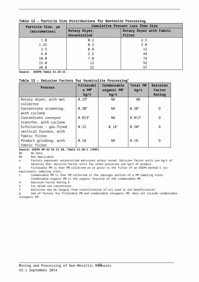
Table 12 – Particle Size Distributions for Bentonite ProcessingParticle Size, m
(micrometres)Cumulative Precent Less Than Size
Rotary Dryer, Uncontrolled Rotary Dryer with Fabric Filter1.01.252.56.0
10.015.020.0
0.20.30.82.27.0
1225
2.53.0
1244749297
Source: USEPA Table 11.25-11
Table 13 – Emission Factors for Vermiculite Processinga
Process Filterable PMb
kg/t
Condensable organic PMc
kg/t
Total PMkg/t
Emission Factor Rating
Rotary dryer, with wet collector 0.29d ND NDConcentrate screening, with cyclone
0.30e NA 0.30e D
Concentrate conveyor transfer, with cyclone
0.013e NA 0.013e D
Exfoliation - gas-fired vertical furnace, with fabric filter
0.32 0.18f 0.50g D
Product grinding, with fabric filter 0.18 NA 0.18 DSource: USEPA AP-42 Ch 11.28, Table 11.28-1 (1995)ND No DataNA Not Applicablea Factors represent uncontrolled emissions unless noted. Emission factor units are kg/t of material fed; emission factor units for
other processes are kg/t of product.b Filterable PM is that PM collected on or prior to the filter of an USEPA method 5 (or equivalent) sampling train.c Condensable PM is that PM collected in the impinger portion of a PM sampling train. Condensable organic PM is the organic
fraction of the condensable PM.d Emission Factor Rating E.e For dried ore concentrate.f Emissions may be largely from volatilisation of oil used in ore beneficiation.g Sum of factors for filterable PM and condensable inorganic PM; does not include condensable inorganic PM.
Mining and Processing of Non-Metallic MineralsV2.1 September 2014
32

TalcTable 14 – Emission Factors for Talc Processinga
ProcessTotal PM
kg/tbEmission
Factor Rating
Natural gas-fired crude ore drying with fabric filterc 0.0020 DPrimary crushing with fabric filter 0.00074 DCrushed talc railcar loading 0.00049 DScreening with fabric filterd 0.0043 DGrinding with fabric filter 0.022 DGrinding with heated makeup air, with fabric filter 0.022 DClassifying, with fabric filtere 0.00077 DPellet drying, with fabric filterf 0.032 EPneumatic conveyor venting, with fabric filterg 0.0018 DPackaging, with fabric filter 0.0090 DCrushed tale storage bin loading, with fabric filterh 0.0036 DGround talc storage bin loading, with fabric filteri 0.0016 DFinal product storage bin loading, with fabric filterh 0.0035 D
Source: USEPA AP-42 Ch 11.26, Table 11.26-1 (1995)a Units are kg/t of production unless noted.b Total PM includes the PM collected in the front half and the inorganic PM caught in the back half (impingers) of an USEPA
Method 5 sampling train.c Filterable PM faction is 60 per cent, and condensable inorganic fraction is 40%.d For crushed talc ore.e For ground talc.f Filterable PM fraction is 56%, and condensable inorganic fraction is 44%.g For final product. Units are kg/t of material conveyed.h Units are kg/t of material loaded into storage bin.i Units are kg/t of material loaded into storage bin.
Table 15 gives emission factors for NPI substance emissions, while Table 16 gives emission factors for organic pollutants emissions, from industrial sand and gravel processing. Table 15 and Table 16 were adapted from USEPA, AP-42, Chapter 11 (1995). In the absence of other data, the emission factors presented in Table 17 for “crushed stone processing” can be used to estimate emissions from corresponding sand and gravel processing sources. The emission factors presented in Table 15 for industrial sand and gravel processing are not recommended as surrogates for construction sand and gravel processing as these materials are processed at much higher moisture contents.
Mining and Processing of Non-Metallic MineralsV2.1 September 2014
33
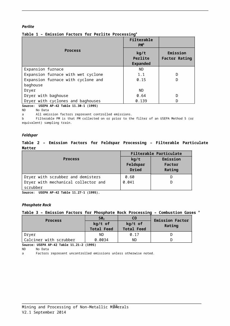
Table 15 – Emission Factors for Industrial Sand and Gravel Processinga
Source Total PM kg/t
NOx
kg/tEmission Factor
RatingSand dryer 0.98b 0.016 E
Sand dryer with wet scrubber
0.019b c C
Sand dryer with fabric filter
0.0053b c D
Sand handling, transfer, and storage with wet scrubber
0.00064d ND D
Sand screening with venturi scrubber
0.0042e ND D
Source: USEPA AP-42 Ch 11.19.1, Table 11.19.1 (1995)ND No dataa Factors represent uncontrolled emissions unless noted. Dryer emission factors in units of kg/t of dried material produced;
other factors in units of kg/t of material stored or screened.b Factors are for filterable PM only. Filterable PM is that PM collected on or prior to the filter of an EPA Method 5 sampling
train. Condensable organic and inorganic PM emission factors are not available. Factors can be considered a conservative underestimate of total PM.
c Control device has no effect on emissions. See factor for uncontrolled emissions.d For dried sand.e Screening of dried sand.
Table 16 – Emission Factors for Industrial Sand and Gravel Processing – Organic Pollutantsa
Source Pollutant Emission Factorkg/t
Emission Factor Rating
Diesel-fired rotarysand dryer with fabric filter (SCC 3-05-027-22)
Formaldehyde 0.0021 D
PAH B[a]Peq 1.54 * 10-7 DSource: USEPA AP-42, Section 11.19.1, Table 11.19-2 (1995)a Factors represent uncontrolled emissions unless noted. Dryer emission factors in units of
kg/tonne of material dried. SCC = Source Classification Code.
As PM10 emissions from limestone and granite processing operations are similar, the emission factors developed from the emission data gathered at limestone and granite processing facilities are considered to be representative of typical crushed stone processing operations. Emission factors for filterable PM and PM10
emissions from crushed stone processing operations are presented in Table 17, adapted from USEPA, AP-42, Chapter 11, (1995).
Mining and Processing of Non-Metallic MineralsV2.1 September 2014
34
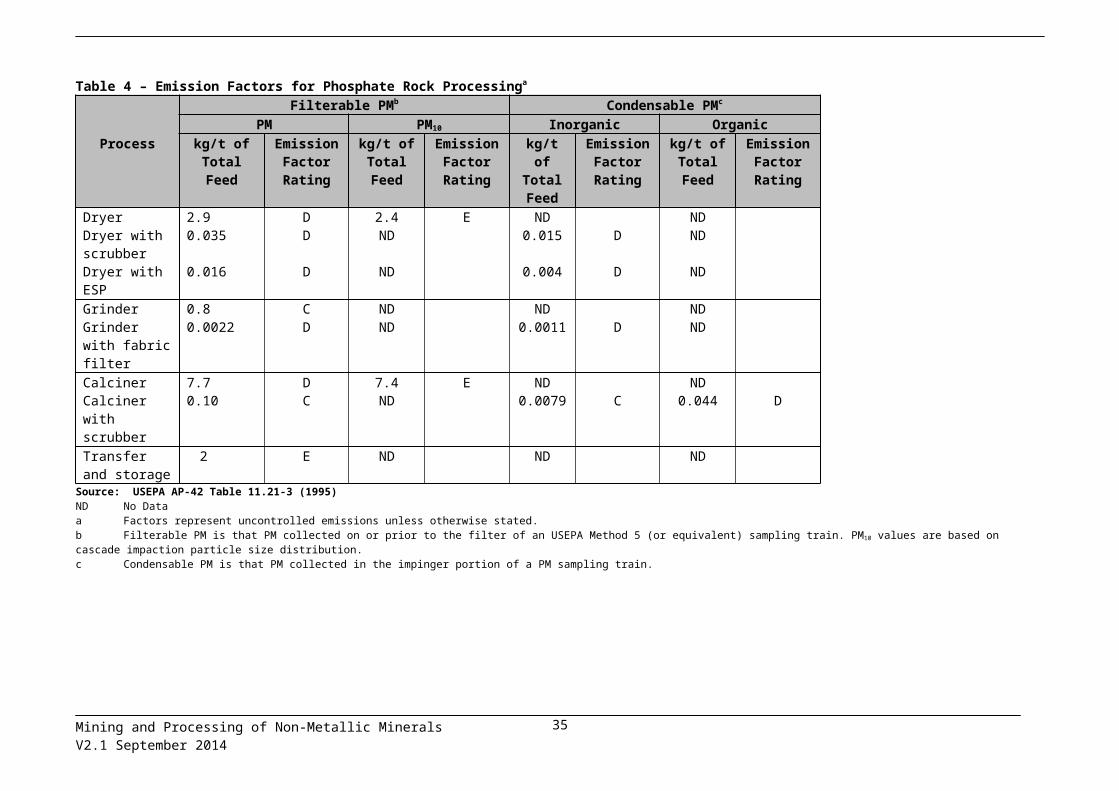
Table 17 – Emission Factors for Crushed Stone Processinga
Sourceb Total Particulate
Matterkg/t
Emission Factor Rating Total
PM10
kg/t
Emission Factor Rating
Screening 0.0125 E 0.0043 CScreening (controlled) 0.0011 E 0.00037 CPrimary crushing ND NDc
Secondary crushing ND NDc
Tertiary crushing 0.0027 E 0.0012 CPrimary crushing (controlled) ND NDc
Secondary crushing (controlled) ND NDc
Tertiary crushing (controlled) 0.0006 E 0.00027 CFines crushing 0.0195 E 0.0075 EFines crushing (controlled) 0.0015 E 0.0006 EFines screening 0.15 E 0.036 EFines screening (controlled) 0.0018 E 0.0011 EConveyor transfer point 0.0015 E 0.00055 DConveyor transfer point (controlled)
0.00007 E 2.3 * 10-5 D
Wet drilling: unfragmented stone ND 4.0 * 10-5 ETruck unloading: fragmented stone
ND 8.0 * 10-6 E
Truck loading: conveyor: crushed stone
ND 5.0 * 10-5 E
Source: USEPA AP-42 Ch11.19.2, Table 11.19.2-1 (2004)ND No dataa Emission factors represent uncontrolled emissions unless noted. Emission factors in kg/t of material throughput.b Controlled sources (with wet suppression) are those that are part of the processing plant that employs current wet
suppression technology similar to the study group. The moisture content of the study group without wet suppression systems operating (uncontrolled) ranged from 0.21 to 1.3 per cent and the same facilities operating wet suppression systems (controlled) ranged from 0.55 to 2.88 per cent. Due to carry over or the small amount of moisture required, it has been shown that each source, with the exception of crushers, does not need to employ direct water sprays. Although the moisture content was the only variable measured, other process features may have as much influence on emissions from a given source. Visual observations from each source under normal operating conditions are probably the best indicator of which emission factor is most appropriate. Plants that employ sub-standard control measures as indicated by visual observations should use the uncontrolled factor with an appropriate control efficiency that best reflects the effectiveness of the controls employed.
c No data available, but emission factors for PM10 emission factors for tertiary crushing can be used as an upper limit for primary and secondary crushing.
Mining and Processing of Non-Metallic MineralsV2.1 September 2014
35

3.2 Emissions to waterEmissions of toxic substances to waterways may pose environmental hazards. Most facilities emitting NPI substances to water are required by their state or territory environment authority to closely monitor and measure these emissions. Existing sampling data can be used to calculate annual emissions to the NPI.
Discharges of triggered NPI substances are considered emissions to water if emitted to surface waters (lakes, rivers, dams, estuaries), coastal or marine waters, or contained in stormwater runoff. The discharge of NPI listed substances to a sewer or tailings dam is not regarded as an emission but a transfer and as such is reportable to the NPI as a transfer
Information concerning emissions to water from the mining and processing of non-metallic minerals can be sourced from the EET Manual for Mining.
3.3 Emissions to landEmissions of substances to land include solid wastes, slurries, sediments, spills and leaks, storage and distribution of liquids, and such emissions may contain NPI-listed substances. Emission sources can be categorised as:
- surface impoundments of liquids and slurries, or - unintentional leaks and spills.
Information concerning emissions to land from the mining and processing of non-metallic minerals can be sourced from the EET Manual for Mining.
Mining and Processing of Non-Metallic MineralsV2.1 September 2014
36
4 Transfers of NPI substances
It is mandatory to report NPI substances that are transferred in waste to a final destination. Transfers are required to be reported if a Category 1, Category 1b or Category 3 reporting threshold is exceeded. For example, if the threshold has been exceeded for the Category 1 substance - lead and compounds - as a result of use of this substance on site, transfers to final destination as well as emissions are reportable. Both emissions and transfers are reportable in kilograms.
There is no requirement to report transfers of:
- substances that are exclusively Category 2a or Category 2b; - substances which are both Category 2a or Category 2b and Category 1 (e.g. copper and
compounds) or Category 1b, in the event that the substance has tripped the Category 2a and 2b threshold only; or
- Total VOC (Category 1a, Category 2a and Category 2b).
General information regarding transfers of NPI substances can be located in the NPI Guide and the Transfers Information Booklet.
Further information concerning transfers of materials from the mining and processing of non-metallic mines can be found in the EET Manual for Mining.
Mining and Processing of Non-Metallic MineralsV2.1 September 2014
37

5 References
Buonicore A J and Davis W T (1992), “Air Pollution Engineering Manual” Published by the (US) Air & Waste Management Association, Van Nostrand Reinhold, New York
Environment Australia (1999), “Emission Estimation Technique Manual for Mining”
Holmes Air Sciences (1998), "Review of Load Based Licensing requirements and exploration of alternative approaches", study carried out for the Minerals' Council of NSW, April 1998
New South Wales Environment Protection Authority (NSWEPA) (1997), "Metropolitan Air Quality Study: Air Emissions Inventory, NSWEPA, Sydney
NERDDC (1988), "Air pollution from surface coal mining: Volume 2 Emission factors and model refinement", National Energy Research and Demonstration Council, Project 921
SPCC (1986), "Air Pollution from Coal Mining and Related Developments", ISBN 0 7240 5936 9
US EPA (1985), "Compilation of Air Pollutant Emission Factors", AP-42, Fourth Edition United States Environmental Protection Agency, Office of Air and Radiation Office of Air Quality Planning and Standards, Research Triangle Park, North Carolina, 27711http://www.ep a .go v / t t n chi e 1 / ap42 . html
US EPA (1998), "Compilation of Air Pollutant Emission Factors", AP-42, Fourth Edition United States Environmental Protection Agency, Office of Air and Radiation Office of Air Quality Planning and Standards, Research Triangle Park, North Carolina, 27711
US EPA, 2006, Emission Factor Documentation for AP-42, Section 11.19.2 Crushed Stone Processing and Pulverized Mineral Processing, United States Environmental Protection Agency, Office of Air Quality Planning and Standards. Research Triangle Park, NC, USAhttp://www.epa.gov/ttn/chief/ap42/ch11/final/c11s1902.pdf
The following EET Manuals are available at the NPI Homepage (http://www. npi.gov.au ):
Emissions Estimation Technique Manual for Fossil Fuel Electric Power GenerationEmissions Estimation Technique Manual for Combustion in BoilersEmissions Estimation Technique Manual for Combustion EnginesEmissions Estimation Technique Manual for Sewage and Wastewater TreatmentEmissions Estimation Technique Manual for Explosives DetonationEmissions Estimation Technique Manual for Mining
Mining and Processing of Non-Metallic MineralsV2.1 September 2014
38
Appendix A: Definitions and abbreviationsTerm Definition
ANZSIC Australian and New Zealand Standard Industrial Classification
AP-42 AP-42, Fifth Edition, Compilation of Air Pollutant Emission Factors
EET Emission Estimation Technique
EF Emission factor
Emission For the purpose of NPI reporting means the release of a substance to the environment, whether in pure form or contained in other matter, and whether in solid, liquid or gaseous form. It does not include the transfer of a substance; however, it does include the release of a substance to the environment, during transfer and from a transfer destination.
Facility Any building, land or offshore site from which an NPI substance may be emitted, together with any machinery, plant, appliance, equipment, implement, tool or other item used in connection with any activity carried out.
Mandatory reporting transfer destination
For the purposes of NPI reporting, mandatory reporting transfer destination means destination for containment, including landfill, tailings storage facility, underground injection or other long term purpose-built waste storage structure; an off-site destination for destruction; an off-site sewage system; or an off-site treatment facility which leads solely to one or more of the above.
NPI National Pollutant Inventory
ORS Online reporting system
PM Particulate Matter
PM2.5 Particulates which have an aerodynamic diameter equal to or less than 2.5 micrometres (2.5m)
PM10 Particulates which have an aerodynamic diameter equal to or less than 10 micrometres (10m)
t Tonne
TET Transfer emission technique
Total VOC Total Volatile Organic Compounds
The NPI defines volatile organic compounds (VOC) as any compound containing carbon that:
1. Has a vapour pressure greater than 0.01 kPa at 293.15 K (20 degrees centigrade), i.e., readily vapourises under normal indoor atmospheric conditions of temperature and pressure; and
2. Is photochemically reactive, i.e., can contribute to photochemical smog production.
Specifically excluded are: carbon monoxide methane acrylamide benzene hexachloro biphenyl chlorophenols
Mining and Processing of Non-Metallic MineralsV2.1 September 2014
39

n-dibutyl phthalate ethylene glycol di-(2-ethylhexyl) phthalate (DEHP) 4,4-methylene bis 2,4 aniline (MOCA) Methylenebis phenol, and toluene-2,4-diisocyanate.
The inclusion of Total VOCs is in recognition of the combined effect of compounds that contribute to smog formation that may not otherwise have been captured due to individual substances not meeting a usage threshold in their own right. The most common sources of Total VOCs emissions are from the storage and use of liquid and gaseous fuels, the storage and use of solvents and the combustion of fuels.
Transfer The transport or movement, on-site or off-site, of substances contained in waste for:
containment;
destruction;
treatment that leads to:
o reuse, recycling or reprocessing;
o purification or partial purifications;
o remediation; or
o immobilisation;
energy recovery.
Usage The handling, manufacture, import, processing, coincidental production or other use of the substance.
USEPA United States Environmental Protection Agency
VOC Volatile Organic Compounds
Voluntary reporting transfer destination
Means a destination for reuse, recycling, reprocessing, purification, partial purification, immobilisation, remediation or energy recovery.
Mining and Processing of Non-Metallic MineralsV2.1 September 2014
40

Appendix B: Erratum
Mining and Processing of Non-Metallic Minerals manual erratum (Version 2.1 – September 2014) – Previous version 2.0 issued August, 2000Page Outline of alterationThroughout Reformatted in line with manual template v1.4
Throughout Removed unnecessary information already covered in other documents. Including: Generic reporting advice (referred to NPI Guide) Mining manual equations, examples, emission factors, control factors, (referred to
Mining Manual) Combustion engines emission factors and references (referred to Combustion
Engines Manual) Combustion in Boilers references (referred to Combustion in Boilers Manual) Transfers information (referred to Transfers Booklet) Removed dated mining examples/references.
1 ANZSIC Codes changed to reflect 2006 codes
Section 3 Added references to other sources of emissions for this industry. Edited content and structure for ease of reading, and limit repetition.
34 Table 16: Polycyclic Aromatic Hydrocarbon emission factor updated to B[a]Peq.
35 Table 17: Emissions factors updated to most recent US EPA Crushed Stone Processing Operations (2004).
Mining and Processing of Non-Metallic MineralsV2.1 September 2014
41