eemmppiirriiccaall ssttuuddyy oonn nneeww bbaassee
TRANSCRIPT

© Daffodil International University i
EEmmppiirriiccaall ssttuuddyy oonn NNeeww BBaassee TTrraannsscceeiivveerr
SSttaattiioonn iinnssttaallllaattiioonn
FFoorr 44GG
By
Shamsuzzaman Shamim
ID: 151-19-1735
This Internship Report is presented in partial fulfillment of the requirements of the Degree
of Bachelor of Science in Electronics and Telecommunication Engineering
Supervised By
Engr. Md. Zahirul Islam
Assistant Professor
Department of ICE
Daffodil International University
DAFFODIL INTERNATIONAL
UNIVERSITY DHAKA-1207, BANGLADESH
December, 2018

© Daffodil International University ii
© Daffodil International University iii
© Daffodil International University iv
© Daffodil International University v
ACKNOWLEDGMENTS
At First, I am like to convey my gratitude to the Almighty for charitable me the right path
while trying the duty.
The real sprit of achieving a goal is finished the way of quality and austere castigation. I
would have never thrived in effecting my task without the teamwork, help and support
provided to me by many personalities.
This internship report would not consume been possible without the provision and direction
of Engr. Md. Zahirul Islam, Assistant Professor, Department of Information and
Communication Engineering, Daffodil International University, Dhaka, under whose
direction I chose this topic.
I would like to rapid my heartiest gratitude to Md. Taslim Arefin, Associate Professor and
Head, Department of Information and Communication Engineering, for his kind help to
surface our thesis and also to other faculty participants, the staffs of the ICE Department of
Daffodil International University.
I must grant with due esteem the perpetual support and endurance of my family members for
final this internship.
Shamsuzzaman Shamim
© Daffodil International University vi
Abstract
Base transceiver station (BTS) support multiple conversation with mobile station on different
frequencies, each carrier signal must be amplified separately. It is possible to provide a signal
power amplifier for each carrier, along with a frequency selective combiner. In the report, a new
BTS installation process is described for 4G in order to provide more coverage by with best deal
and best cellular technologies like 3Gor 4G. To install a new BTS, some indoor and outdoor
equipment id needed which is studied empirically and mentioned their role in this report.
Introduction of GSM antenna, microwave antenna, different types of transmission cars is
addressed empirically.

© Daffodil International University vii
TABLE OF CONTENT
Chapter Page
Chapter 1: Introduction
1.1 Introduction 1
1.2 About Starlink Engineering Limited 1
1.3 Company profile 2
1.4 Environmental health and safety 2
1.5 Objective of the Report 3
1.6 Summary of the Report 3
Chapter 2 Cullular System and GSM Techology
2.1 Cellular System 4
2.2 What is cell? 5
2.3 Concept 6
2.4 Frequency Reuse 7
2.5 Handover 8
2.6 Traffic Engineering 9
2.7 GSM (Global System for Mobile Communications) 10
2.8 GSM system overview 10
2.9 GSM system architecture 11
2.10 Mobile station 12
2.11 The SIM 13
2.12 Base Station Subsystem (BSS) 14
2.12.1 Base Transceiver Station (BTS 14
2.13 Network Switching Subsystem (NSS) 14
2.13.1 Mobile Services Switching Centre (MSC) 15
2.13.2 Home Location Register (HLR) 16
2.13.3 Visitor Location Register (VLR) 16
2.13.4 Equipment Identity Register (EIR) 16
2.13.5 Authentication Centre (AuC) 16
2.13.6 Gateway Mobile Switching Centre (GMSC) 16
© Daffodil International University viii
2.13.7 SMS Gateway (SMS-G) 17
2.14 Operation and Support Subsystem (OSS) 17
2.15 GSM network interfaces list 17-18
2.16 GSM security 19
2.17 GSM frame structure 20
Chapter 3: Types of Cullular Network Tcehologies
3.1 Definition 21
3.2 First generation 21
3.3 2G second-generation 21-22
3.3.1 2.5G (GPRS) 22
3.3.2 2.75G (EDGE) 22
3.4 3G third generation 23
3.5 4G fourth generation 23-24
3.6 Fifth Generation (5G) 23-23
Chapter 4:New Base Trenscevier Station Installation
4.1 Introduction 25
4.2 Why 25
4.3 Indoor Equipment of BTS 25-26
4.3.1 BTS Cabinet 27
4.3.2 BBU-Base Band Unit 27
4.3.3 MRFU 31-32
4.3.4 Rectifier 32
4.3.5 Automatic Voltage Regulator (AVR) 33
4.3.6 Battery Rack 34
4.3.7 Circuit breaker 34
4.3.8 Fuse 35
4.3.9 Ground Bars 36
4.3.10 Direct Current Distribution Unit 36-37
4.4 Transmission Rack 37-38
4.5 Other indoor unit 39

© Daffodil International University ix
4.5.1 Smoke Detectors and Fire alarm 39
4.5.2 Door Alarm 40
4.5.3 Water Sensor 40
4.5.4 Temperature Sensor and Air-Condition 41
4.5.5 Ladder and Feeder Hole 41
4.6 Outdoor Equipment 42
4.6.1 RRU 42
4.6.2 GSM Antenna 43-44
4.6.3 Microwave Antenna 43-43
4.6.4 Feeder Cable 44
4.6.5 CPRI Cable 45
4.6.6 Connector 45
4.6.7 Thundering Arrestor 45
4.7 BTS Commissioning 45
4.7.1 BTS Commissioning procedure 46-49
Chapter 5: Conclusion
5.1 Conclusion 50
5.2 Limitation of the work 50
Refarences 51-52
© Daffodil International University x
List of Figures
Figure Name Page
Fig 2.1 Cellular system 4
Fig 2.2: Cell 5
Fig 2.3: Small Cell 5
Fig 2.4: Cellular Concept 6
Fig 2.5: Frequency Reuse 8
Fig 2.6: 4 types of handover 8
Fig 2.7: Handover decision 9
Fig 2.8: GSM system architecture 12
Fig 2.6: User device 13
Fig 2.9: SIM 13
Fig 2.10: BSC 14
Fig 2.11: MSC 15
Fig 3.1: 5G 23
Fig 4.1: BTS Cabinet 26
Fig 4.2: BBU 27
Fig 4.3: UBBP 28
Fig 4.4: UMPT 29
Fig 4.5: UPEU 30
Fig 4.6: WMPT 30
Fig 4.7: GMPT 31
Fig 4.8: MRFU 31
Fig 4.9: Rectifier 33
Fig 4.10: AVR 34
Fig 4.11: Battery rack 34
Fig 4.12: Generator 35
Fig 4.13: Fuse 36
Fig 4.14: Ground Bars 36
Fig 4.15: DCDU 37
© Daffodil International University xi
Fig 4.15: Transmission Rack 38
Fig 4.16: Smoke sensor 39
Fig 4.18 Door alarm 40
Fig 4.19: Water Sensor 40
Fig 4.20: Air con and temperature sensor 41
Fig 4.22: RRU 42
Fig 4.23: GSM antenna 44
Fig 4.25: Connector 45

© Daffodil International University 1
Chapter1
Introduction
1.1 Introduction
This paper contains what is telecommunication? Telecommunication system, types of cellular
network generation. What is base transceiver station. How is install new base transceiver for 4G
cellular network. telecommunication define as transmit and receive all type of data like voice
information, video information data etc over significant distances by cellular network. To transmit
and receive information in telecom system use different type of media like cable which can be
optical fiber, different types of wave with different frequency wave must be electromagnetic
wave. BTS full form is base transceiver station. BTS provide connection between mobile user and
mobile operator. Bangladesh mobile operator are GP, Robi, Airtel, teltalk. To communicate
properly have to communication technologies like GSM. CDMA in Bangladesh basically use
GSM also have other communication method like Wi-Fi, LAN, WAN, WiMAX. BTS is basically
install for GSM system. New Base Transceiver Station install for cover that area where no
network is existing before. Increase the network coverage to connect more user or MS to the
network.
1.2 About Starlink Engineering Limited.
Starlink Engineering Limited is an Engineering servicing company providing full scope of
engineering services like initial Site Survey, Planning, Installation, Commissioning, Operation
and Maintenance as well as network optimization in the field of Telecommunication and Info-
rmation Technology. Starlink Engineering Limited was started in 2008 by a group of young and
passionate Engineering Team to partnership with different vendors, Telecom operators and
corporate enterprises in Bangladesh. Starlink Engineering Limited was established in 2008.
Company have won many Achievement awards over the years, most recently the 2011 Excellent
Development Award in GP Swap Project from the Huawei Technologies (Bangladesh) Ltd. These
complement similar awards in 2007, 2009 and 2010.

© Daffodil International University 2
1.3 Company Profile
Name :
Starlink Engineering Limited.
Address : Flat# A-1, House# 83, Road# 23, Gulshan, Dhaka-1212
Telephone : +88029862208
Email : E-mail: [email protected]
Website : http://www.starlinkengineering.com
1.4 Environmental health and safety
Star Link understands the risk involved in working onsite. Hence it is our top most priority to
ensure proper security and precautions for the employees.
Star Link strongly maintains the rules and regulations for on-site technical persons. Also, Star
Link is committed to its customer as well as its employees to provide them all the safety manuals
and materials while working.
StarLink proudly announces that at the beginning of this year a board meeting decides that
following are the key safety precautions that all the employees must follow during work
All the employees must use Helmet while working in BTS/MW or Tower sites
All the employees must use SHOES while working
All the employees must use SFETY BELT while working on TOWER
All the employees must use HAND GLOVES while working
All the employees must be educated or informed enough so that they can understand and
oblige by any safety requirements that are imposed by the CUSTOMER
All the employees must not wear any metallic or conductive equipment’s while working
on power materials
© Daffodil International University 3
Concern persons must arrange meeting or training in each 3 months or beginning of a
major project to train the employees about maintaining the safety and quality of
installation and commissioning
Consecutive breach of safety regulations will result in punishment or termination of any
employee.
1.5 Objective of the Report
The main objectives of this report are as follows:
1. Cellular network: GSM System.
2. Types of cellular network technologies.
3. New BTS installation for 4G
1.6 Summary of the Report
The objective of this Internship is to improve an effective knowledge in Subcon in Sterlink
Engineering limited. In The First chapter, I have termed the Details & objective an overall view
that I am going to instrument during this internship work and I would describe the background of
sterlink Engineering Limited. company EHS rule.
The Second Chapter, Cellular System and GSM Technology
The Third chapter is describing, Cellular network generation
The last one is Chapter Four that is BTS installation for 4G and
Chapter five Conclusion.
© Daffodil International University 4
Chapter 2
Cellular System and GSM Technology.
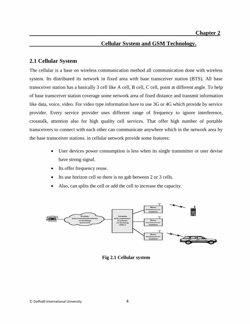
2.1 Cellular System
The cellular is a base on wireless communication method all communication done with wireless
system. Its distributed its network in fixed area with base transceiver station (BTS). All base
transceiver station has a basically 3 cell like A cell, B cell, C cell, point at different angle. To help
of base transceiver station coverage some network area of fixed distance and transmit information
like data, voice, video. For video type information have to use 3G or 4G which provide by service
provider. Every service provider uses different range of frequency to ignore interference,
crosstalk, attention also for high quality cell services. That offer high number of portable
transceivers to connect with each other can communicate anywhere which in the network area by
the base transceiver stations. in cellular network provide some features:
User devices power consumption is less when its single transmitter or user devise
have strong signal.
Its offer frequency reuse.
Its use horizon cell so there is no gab between 2 or 3 cells.
Also, can splits the cell or add the cell to increase the capacity.
Fig 2.1 Cellular system

© Daffodil International University 5
2.2 What is cell?
Larger area divided into small no.of area.
Shape is hexagonal.
Each with its own base station and set of frequencies.
Fig 2.2 Cell
Small cells, which have a smaller coverage area than base stations, are categorized as follows:
Microcell range 2 km
Picocell range 200 m
Femtocell almost 10 m
Fig2.3 Small Cell
© Daffodil International University 6
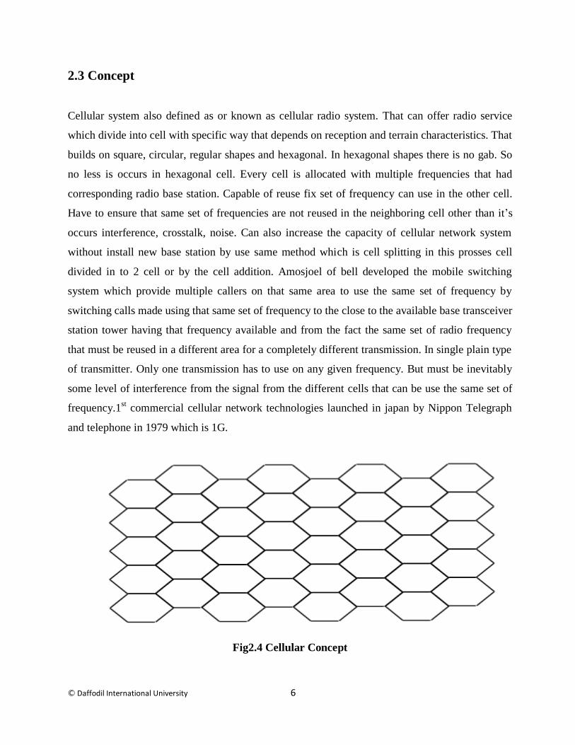
2.3 Concept
Cellular system also defined as or known as cellular radio system. That can offer radio service
which divide into cell with specific way that depends on reception and terrain characteristics. That
builds on square, circular, regular shapes and hexagonal. In hexagonal shapes there is no gab. So
no less is occurs in hexagonal cell. Every cell is allocated with multiple frequencies that had
corresponding radio base station. Capable of reuse fix set of frequency can use in the other cell.
Have to ensure that same set of frequencies are not reused in the neighboring cell other than it’s
occurs interference, crosstalk, noise. Can also increase the capacity of cellular network system
without install new base station by use same method which is cell splitting in this prosses cell
divided in to 2 cell or by the cell addition. Amosjoel of bell developed the mobile switching
system which provide multiple callers on that same area to use the same set of frequency by
switching calls made using that same set of frequency to the close to the available base transceiver
station tower having that frequency available and from the fact the same set of radio frequency
that must be reused in a different area for a completely different transmission. In single plain type
of transmitter. Only one transmission has to use on any given frequency. But must be inevitably
some level of interference from the signal from the different cells that can be use the same set of
frequency.1st commercial cellular network technologies launched in japan by Nippon Telegraph
and telephone in 1979 which is 1G.
Fig2.4 Cellular Concept
© Daffodil International University 7
2.4 Frequency Reuse
In the frequency reuse, use the same frequency aging and aging to avoid the miss use of
frequency. Frequency reuse procedure become easier with hexagonal cell shape. In GSM system
frequency reuse factor is 1/K. In CDMA its 1. Config cells to assigned different frequencies to
avoid interference or crosstalk. Basically, frequency reuse in closer cells. Minimum 10 to high 50
frequency allow for each cell.
Cellular system on of the beauty or most important part is frequency reuse. That Increase the
cellular system coverage and capacity without add extra base transceiver station. Frequency reuse
in only closer cell which shape is hexagonal. Adjacent cells have to use different frequencies.is
the tow cells far ways from to each other than there is no problem to frequency reuse there no
tension for crosstalk. This prosses consume the less power. There are 2 things require to observe
frequency reuse that is distance D and reuse factor. Now D is obtaining by:
√
R is known as cell radius and N is known as cells per cluster.
Now the frequency reuse factor which is 1/K. In here K is the number of cells that don’t use the
same set of frequency which use for transmission. Basic number of frequency reuse factor age
1by3,1by4,1by7,1by9 and 1/12. In same BTS site if each of the cell direction is different in case
can use same frequency in each of cell. Basically, a base transceiver station has 3 cell which is A
cell, B cell, C cell. Each cell allows to use a number of frequency channels corresponding to the
bandwidth of B/K. Where B is available bandwidth. In same way each sector can be use
bandwidth of B/NK,
Advantage of frequency reuse:
Require low bandwidth.
Minimize the number BTS
Low cost and maintenance so easy.
© Daffodil International University 8
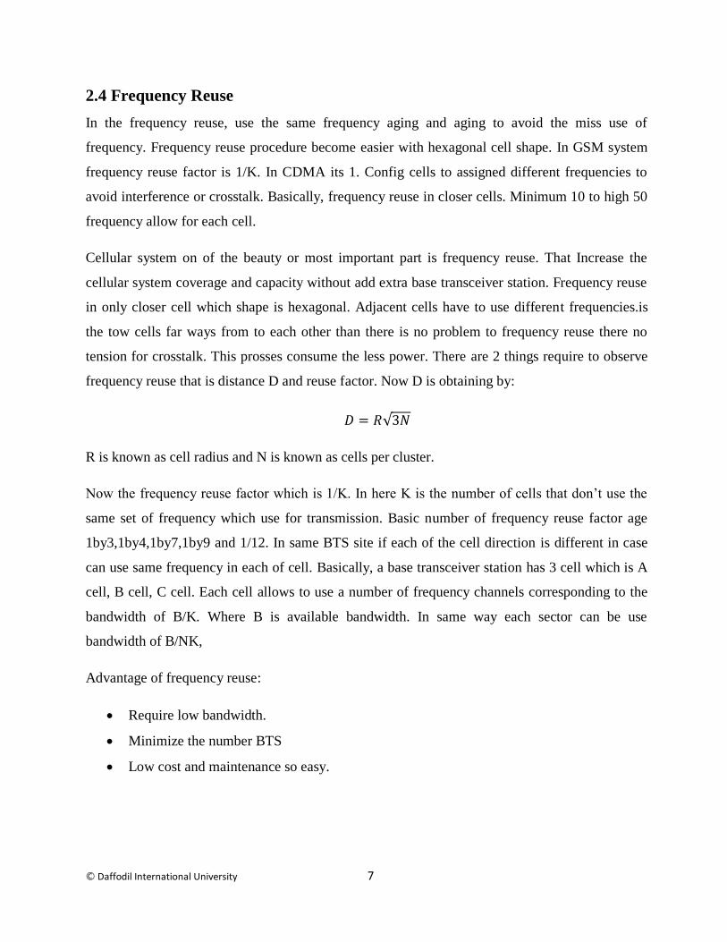
Fig2.5Frequency Reuse
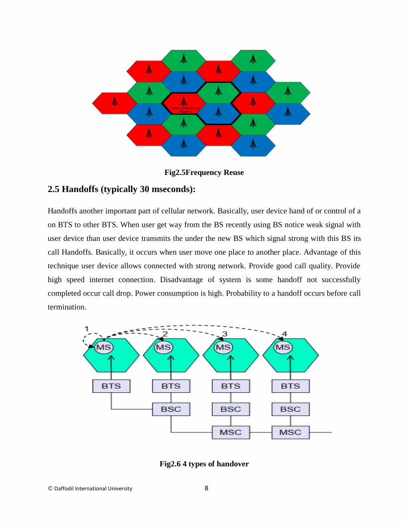
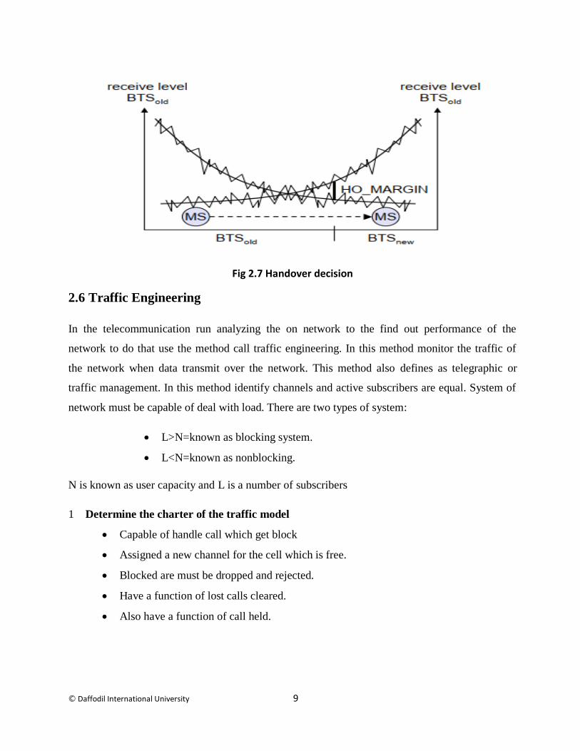
2.5 Handoffs (typically 30 mseconds):
Handoffs another important part of cellular network. Basically, user device hand of or control of a
on BTS to other BTS. When user get way from the BS recently using BS notice weak signal with
user device than user device transmits the under the new BS which signal strong with this BS its
call Handoffs. Basically, it occurs when user move one place to another place. Advantage of this
technique user device allows connected with strong network. Provide good call quality. Provide
high speed internet connection. Disadvantage of system is some handoff not successfully
completed occur call drop. Power consumption is high. Probability to a handoff occurs before call
termination.
Fig2.6 4 types of handover
© Daffodil International University 9
Fig 2.7 Handover decision
2.6 Traffic Engineering
In the telecommunication run analyzing the on network to the find out performance of the
network to do that use the method call traffic engineering. In this method monitor the traffic of
the network when data transmit over the network. This method also defines as telegraphic or
traffic management. In this method identify channels and active subscribers are equal. System of
network must be capable of deal with load. There are two types of system:
L>N=known as blocking system.
L<N=known as nonblocking.
N is known as user capacity and L is a number of subscribers
1 Determine the charter of the traffic model
Capable of handle call which get block
Assigned a new channel for the cell which is free.
Blocked are must be dropped and rejected.
Have a function of lost calls cleared.
Also have a function of call held.
© Daffodil International University 10
Traffic intensity
Load of the system define as:A=yh
y=unit per time attempted of rate of calls.
h=call successfully hold par time.
A=in hold period number of calls arriving.
2.7 GSM (Global System for Mobile Communications)
European telecommunication standards institute the introduce advance wireless mobile
communication system which is GSM (Global System for Mobile Communications). GSM is
second generation cellular network system. This system uses the circuit switching system to data
transport. Than get update it became 2.5G(GPRS) that can provide call plus data services. Then
came 2.7G(EDGE) in here improved the data and voice quality. Then UMTS standard introduce
the 3G third generation cellular network system. It’s also part of GSM technologies. As usual
network became 4G and 5G almost ready to run. They all part of GSM system. Bangladesh
basically used GSM. CDMA is no more used in BD. All BTS tower are installation for GSM type
network. BTS interconnection between user device and service provider like robi, gp airtell,
teletalk. BTS user different type of transmission card to transmission for 2G used GMPT. For 3G
used UMPT or WMPT. For 4G used UMPT card for transmission.
2.8 GSM system overview
The GSM system run on the method of frequency and time division modulation. Data and voice
must be carrier by the frequency carrier and time slot number (TDM). Cellular system are radius
the signal with low power by each of BTS cell, Acell,Bcell,cell. Frequency Division Duplex
(FFD) use for user uplink and downlink which assigned with different frequencies. For data used
Time division access. (TDMA) frame. Easy to say system divided into time slots.
© Daffodil International University 11
2.9 GSM system architecture
Before build something needs the architecture to build in proper way and what element use to
build to right architecture. In cellular system use the same method to build right architecture for
cellular network. As same GSM, to create right architecture. To build right architecture of GSM
system require same element. GSM is 2G architecture but it’s still uses on the cellular network.4G
3G,5G also use that architecture. Can say muster structure of cellular system is GSM architecture.
This system was introduced in 1990s and element of this also introduce in this year. Basic
element use in system are:
Mobile station (MS)
1. User device
2. Subscriber identity module
Network switching subsystem (NSS)
1. Mobile switching center (MSC)
2. Home location register (HLR)
3. Equipment identity register (EIR)
4. Authentication center (AUC)
5. Visitor location register (VLR)
Base station subsystem (BSS)
1. Base transceiver station (BTS)
2. Base station controller (BSC)
Operation and support subsystem (OSS or RSS)
In this GSM structure mobile station connected with the base station subsystems then BSS
connected with the NSS. Network switching subsystems is connected with the another NSS. The
architecture of GSM system given blow:

© Daffodil International University 12
Fig2.8 GSM system architecture
2.10 Mobile station
User device, computer, device which connected with the network are call Mobile station.
Basically, is a cell phones other types of device which have sim inside in. User device increased
in those year. Mobile station basically connected with the base transceiver station on the BSS.
communicate between mobile station and base transceiver station must need SIM. To power the
SIM or boost the signal need device which is mobile station or user device. Without SIM and
mobile station GSM structure is incomplete.

© Daffodil International University 13
Fig 2.7 user device
2.11 The SIM
Sin is known as a subscriber identity module. Also call subscriber identification module (SIM). In
the SIM a electric cheap build on or can say an integrated circuit inside the SIM. The SIM
basically have subscriber or user identity. Can say user information like SIM number which
depend of the operator. In Bangladesh first 3 number +088 is Bangladesh code next 3 number is
operator identity and last 6 six number for user identity. The cant fun alone needs a device to run
which call user device. Without sim card MS is useless. SIM must be needed to complete the
GSM structure. A SIM card have few thing or programmer like personal identity (PIN) which
given by user. If user forgot the PIN use PIN unblocking KEY (PUK) which given by the
operator. Also have mobile station ISDN number (MSISDN), Temporary Mobile Subscriber
Identity (TMSI) and if SIM is stolen than have International Mobile Subscriber Identity (IMSI) is
can’t be change. Also have same security for data like The individual key (Ki), The algorithm for
authorization and ciphering and the last one is The Cipher key (Kc).
Fig2.9SIM
© Daffodil International University 14
2.12 Base Station Subsystem (BSS)
After the mobile station GSM architecture have the base station subsystem (BSS) part. Inside this
have 2 impotent elements which is base transceiver station (BTS) and Base Station Controller
BSC.
2.12.1 Base Transceiver Station (BTS):
The base transceiver station (BTS) is a part of BSS in the GSM cellular system. BTS transmit
signal in fix area which assigned for it. BTS receive the signal from the MS unit. Transmit the
Signal in the MSC in the GSM architecture. Use Um interface to concoction between mobile
station unit and base transceiver station. BTS run on commercial power, electrical generator, Soler
energy and battery. BTS have 4 type Pole site, green field, roof top, guy mast towers.
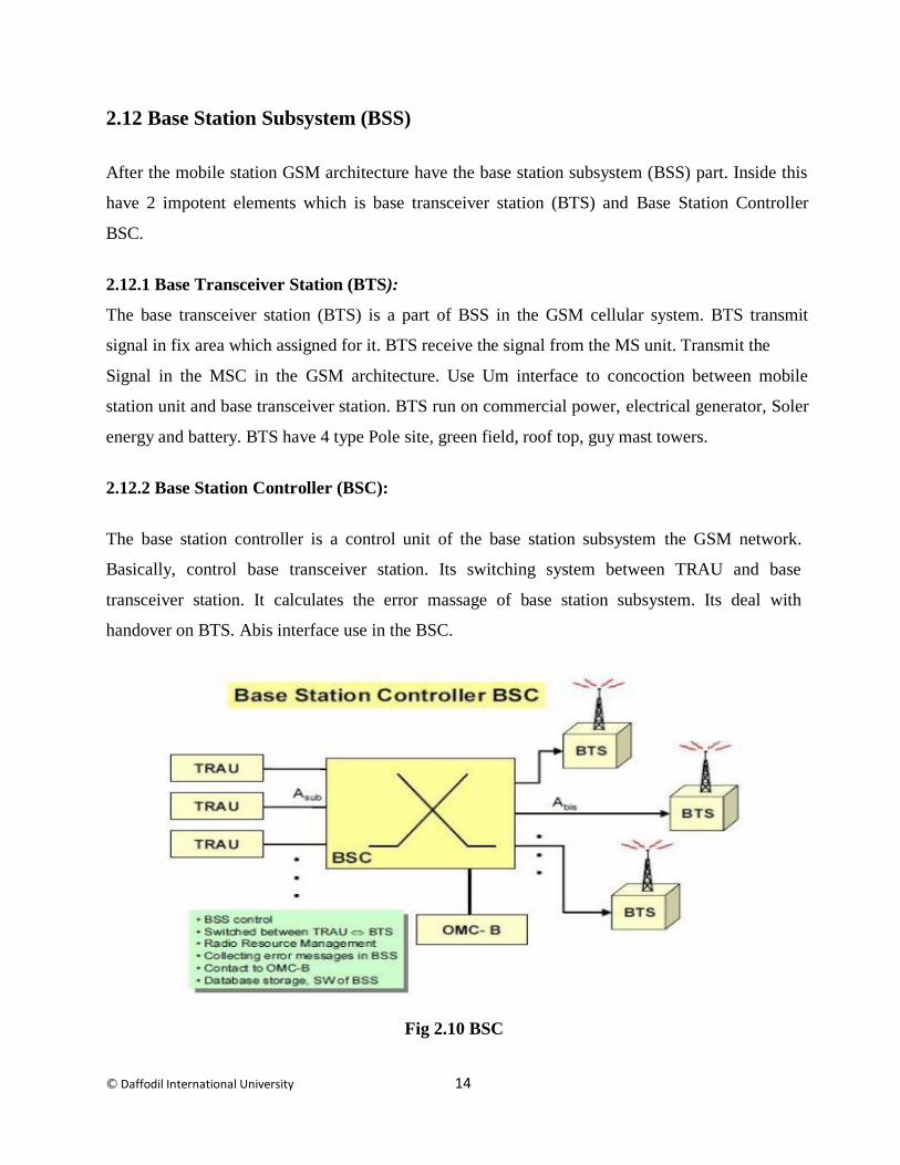
2.12.2 Base Station Controller (BSC):
The base station controller is a control unit of the base station subsystem the GSM network.
Basically, control base transceiver station. Its switching system between TRAU and base
transceiver station. It calculates the error massage of base station subsystem. Its deal with
handover on BTS. Abis interface use in the BSC.
Fig 2.10 BSC
© Daffodil International University 15
2.13 Network Switching Subsystem (NSS)
Network switching subsystem is one of the most part of the GSM architecture. It’s also known as
core part of the system. It’s have major element of the network which is MSC,HLR,VLR,EIR,
AuC etc
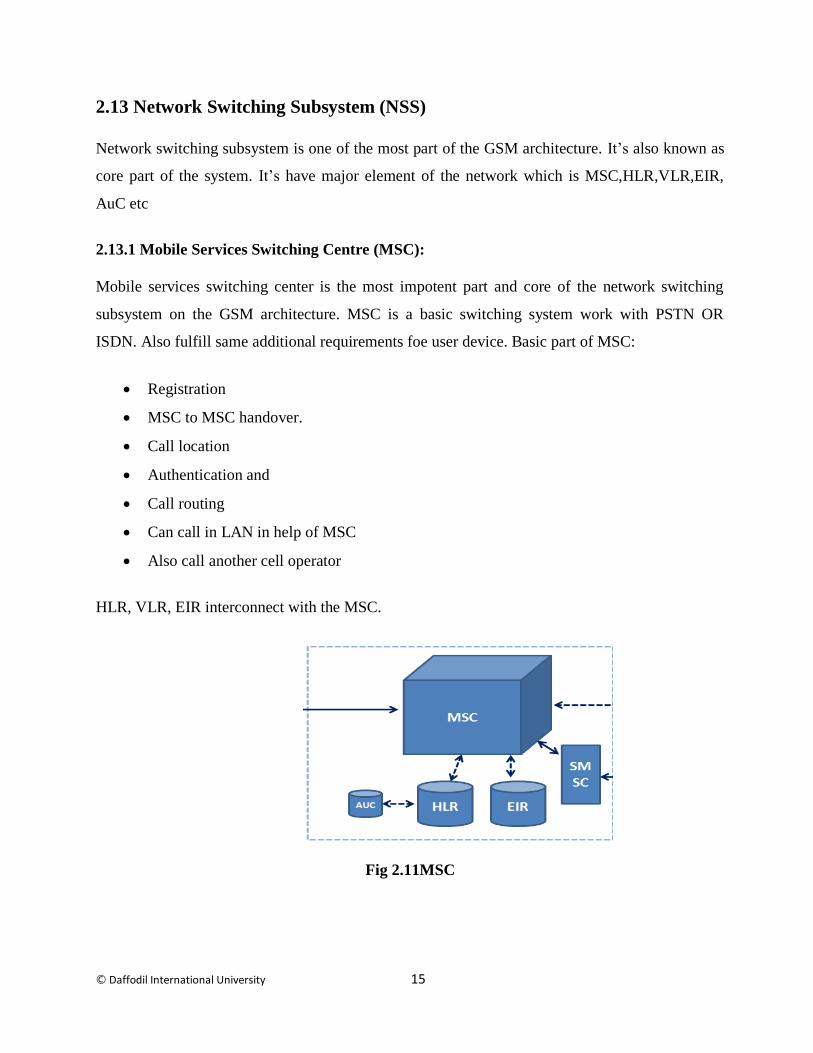
2.13.1 Mobile Services Switching Centre (MSC):
Mobile services switching center is the most impotent part and core of the network switching
subsystem on the GSM architecture. MSC is a basic switching system work with PSTN OR
ISDN. Also fulfill same additional requirements foe user device. Basic part of MSC:
Registration
MSC to MSC handover.
Call location
Authentication and
Call routing
Can call in LAN in help of MSC
Also call another cell operator
HLR, VLR, EIR interconnect with the MSC.
Fig 2.11MSC
© Daffodil International University 16
2.13.2 Home Location Register (HLR):
Home location register is part of NSS of GSM cellular network. HLR interconnection between the
MSC. When a user stays maximum under the same network or in the same exchange it can call
home network. HLR have all the information of the user or home device in the database. Home
location register have user device location, call information, call routing information. If the user
changes the device HLR update the information on system. HLR also contain IMEI number.
2.13.3 Visitor Location Register (VLR):
When the user far away from the home network and going to stay on the other network for short
time its call visitor location register. When user in the VLR HLR transfer all information of the
user in VLR. Than VLR take care from the user. It’s an impotent part of NSS system on GSM.
VLR Interconnection with MSC.
2.13.4 Equipment Identity Register (EIR):
When same user device tries to inter the network have to verify on EIR. EIR entity the user device
information. Make decision about whether that device allowed for the network or not. Every cell
phone has international mobile equipment identity. By the IMEI number can know about user
device location if the user change the SIM also can trace the cell phone. EIR block the unregister
mobile. Bangladesh don’t have EIR number. EIR connected with MSC.
2.13.5 Authentication Centre (AuC):
The AuC is a database, that contains the user SIM secret key. It’s so protected database. It is used
for ciphering on the radio channel and authentication.
2.13.6 Gateway Mobile Switching Centre (GMSC):
The GMSC is the point to which a ME ending call is at first steered, with no information of the
MS's area. The GMSC is in this manner responsible for getting the MSRN (Mobile Station
Roaming Number) from the HLR dependent on the MSISDN (Mobile Station ISDN number, the
"index number" of a MS) and directing the call to the right visited MSC. The "MSC" some
© Daffodil International University 17
portion of the term GMSC is deluding, since the passage task does not require any connecting to a
MSC.
2.13.7 SMS Gateway (SMS-G):
The SMS-G or SMS portal is the term that is utilized to altogether depict the two Short Message
Services Gateways characterized in the GSM benchmarks. The two portals handle messages
coordinated in various ways. The SMS-GMSC (Short Message Service Gateway Mobile
Switching Center) is for short messages being sent to a ME. The SMS-IWMSC (Short Message
Service Inter-Working Mobile Switching Center) is utilized for short messages started with a
portable on that arrange. The SMS-GMSC job is like that of the GMSC, though the SMS-IWMSC
gives a settled passage to the Short Message Service Center.
2.14 Operation and Support Subsystem (OSS)
The operation support subsystem provided operational support hole GSM cellular system
network. That do monitor and control parts in hole GSM system. Also maintains the traffic of the
BSS. It must be noticed that as the quantity of BS increments with the scaling of the supporter
populace a portion of the upkeep errands are exchanged to the BTS Its interconnection between
BSC and NSS. Minimums the system cost.
2.15 GSM network interfaces.
Various type of interface is given blow.
Um interface To communication or concoction between user device and base transceiver
station have use that interface which Um interface. that interface connate the user with the
network. Also used ISDN LAPD for signaling.
Abis interface To communicate or connate between BSC and BTS use the Abis interface.
Control radio frequency which assigned for BTS and radio equipment.
A interface To maintain good communication between the BSS and the MSC have to use
protocol or interface in that case can use A interface. Carries information use that interface
© Daffodil International University 18
with enable channels. BSS serviced the mobile equipment to timeslots and like to be
allocated channel.
B interface To maintain communication between the MSC and the VLR have use
interface or the protocol which is B interface. This interface also known as the MAP/B
protocol. The MSC need access from data regarding a MS located in its area to use that B
interface.
C interface To maintain communication between GMSC or HLR and SMS-G have to
user that interface which is C interface. When same user make call from out side of the
network like LAN or another area have to pass the gateway to do that required the routing
information to make successful call. This interface also known as MAP/C protocol.
.D interface To maintain communication between VLR and HLR have to use that
interface which D interface. That also known as the MAP/D protocol. Exchange the data
uses that interface to the management and to the location of the ME.
E interface To communicate with another network MSC or communication between 2
MSC have use that interface which E interface also known as the MAP/E interface.
F interface To maintain communication between EIR and MSC have to be use the F
interface. Also known as the interface is MAP/F protocol. The correspondences along this
interface are utilized to affirm the status of the IMEI of the ME accessing the system.
G interface When one exchange VLR try to communicate with another exchange VLR
have to use G interface. Using that interface VLR transfer information of user to another
VLR during Location update. Also known as the MAP/G protocol.
H interface To send short message use H interface. To communication between SMS-G
and MSC use that interface and is also known as MAP/H
I interface To communication between MSC and ME use that interface which is I
interface. Also known as MAP/I protocol.
© Daffodil International University 19
2.16 GSM security
GSM was planned to be a protected remote framework. It has considered the client verification
utilizing a pre-shared key and test reaction, and over-the-air encryption. Nonetheless, GSM is
powerless against various sorts of assault, every one of them went for an alternate piece of the
system.
The improvement of UMTS presented a discretionary Universal Subscriber Identity Module
(USIM), that utilizes a more drawn out verification key to give more noteworthy security, and
commonly validating the system and the client, while GSM just verifies the client to the system
(and not the other way around). The security display in this way offers secrecy and verification,
yet constrained approval abilities, and no non-revocation.
GSM utilizes a few cryptographic calculations for security. The A5/1, A5/2, and A5/3 stream
figures are utilized for guaranteeing over-the-air voice protection. A5/1 was produced first and is
a more grounded calculation utilized inside Europe and the United States; A5/2 is more fragile
and utilized in different nations. Genuine shortcomings have been found in the two calculations: it
is conceivable to break A5/2 progressively with a ciphertext-just assault, and in January 2007,
The Hacker's Choice began the A5/1 splitting task with plans to utilize FPGAs that permit A5/1 to
be broken with a rainbow table assault. The framework bolsters various calculations so
administrators may supplant that figure with a more grounded one. Since 2000 unique endeavors
have been made so as to split the A5 encryption calculations. Both A5/1 and A5/2 calculations
have been broken, and their cryptanalysis has been uncovered in the writing. For instance,
Karsten Nohl [de] built up various rainbow tables (static qualities which diminish the time
expected to do an assault) and have discovered new hotspots for He said that it is conceivable to
manufacture "a full GSM interceptor...from open-source segments" however that they had not
done as such in light of lawful concerns. Nohl asserted that he had the ability to catch voice and
content discussions by mimicking another client to tune in to phone message, make calls, or send
instant messages utilizing a seven-year-old Motorola cellphone and decoding programming
accessible for nothing on the web. GSM utilizes General Packet Radio Service (GPRS) for
information transmissions like perusing the web. The most generally sent GPRS figures were
openly broken in 2011. The scientists uncovered blemishes in the normally utilized GEA/1 and

© Daffodil International University 20
GEA/2 figures and distributed the open-source "gprsdecode" programming for sniffing GPRS
systems. They likewise noticed that a few transporters don't scramble the information (i.e.,
utilizing GEA/0) so as to recognize the utilization of traffic or conventions they don't care for
(e.g., Skype), leaving clients unprotected. GEA/3 appears to remain generally difficult to break
and is said to be being used on some progressively present-day systems. Whenever utilized with
USIM to avert associations with phony base stations and downsize assaults, clients will be
secured in the medium term, however movement to 128-piece GEA/4 is still suggested.
2.17 GSM frame structure
The most impotent part is GSM architecture is GSM frame. Its have 8 time slots, each of them
used for different users within the TDMA system in millisecond. That minimum the number of
slots. In this system mobile equipment can’t transmit and receive at the same time.
Burst period is the fundamental unit. It’s existed for approximately 57 milliseconds. Those type of
8 burst period build together in a TDMA frame or time slots which exist for approximately 4.61
millisecond. For one physical channel of each TDMA frame one burst channel is assigned.
Traffic and control two types of channel assigned for BTS. This channel basic architecture
divided into 2 different types of frame one is assigned for control on the frequency and another
one is assigned for traffic carrier frequency.

© Daffodil International University 21
Chaptere 3
Types of cellular network technologies
3.1 Definition
With the time cellular network types change for good. It came with generation. Each of
generation came with new technique, New schemas, improve uplink and downlink speed. In this
chapter we talk about each of mobile telecommunication generation. Which is 1G,2G,3G,4G as
well as 5G.
3.2 First generation
In early 1982 world was introducing with first wireless cellular network which finally done in
1990 its known as 1G. its only offer voice services no data services in this network. Allows to
calls in one country. It’s based on full analog system. This named the technology Advanced
mobile phone system (AMPS). Consume high power to operated and poor handoff system. User
device come with big size. Channel capacity only 30 kHz and frequency band can use for this
system only 824-894 MHz Use FDMA and frequency modulation (FM)
The Push to Talk (PTT). It has low capacity, unreliable handoff, poor voice links, and no security
at all since voice calls were played back in radio towers, making these calls susceptible to
unwanted eavesdropping by third parties.
3.3 2G second-generation
After the few years’ time of 1G Finland By Radiolinja launched 1st commercial network GSM
which also call 2G 2nd
generation cellular network in 1991. It’s a big innovation in cellular
network. It provides voice and data service.2G first introduce data transform system in the
network.in 2nd
generation network can send text messages. Also add new service like MMS,
picture messages. Provide good quality voice services. Data transform speed in 26kbps to 64

© Daffodil International University 22
kbps. Run on the system in full digital way here is 1G is analog. Increases big number of
capacities in the network. No video steaming service in the network.
2.3.1 2.5G (GPRS)
Few year later 2G get updated to 2.5 which also call as second and half generation cellular
network. This system uses packet-switching and circuit-switching. In this way data speed become
so high no extra technique needs to use. This generation also known as GPRS. It’s provided 64
to144 kbps. Faster wap browsing than 2G. Possible send E-mail with this speed. Base in this
generation start to build camera phone.
3.3.2 2.75G (EDGE)
In 2003 2G generation add new technique in this family which is 2.75G. Also known as EDGE
cellular network. This generation speed is higher than 2.5G. Its use 8PSK encoding to increases
the internet speed. In this technique can possible video steaming. 2.75G or EDGE is developed by
AT&T in the United States. Also known as Enhanced GPRS.
3.4 3G third generation
The international telecommunication Union introduce third generation or 3G cellular network for
mobile telecommunication. It’s come form 2.5G and 2.75G GSM system. This generation internet
speed is so high up to 7mbps maximum 21mbps. With this speed can do many things like online
TV. Online video, online sport, video calls etc. Many new devices have been built to run with this
speed on this generation network like laptop which have high configuration. Life become so easy
with is generation. Also develops round this generation are communication Global Positioning
System (GPS), Video Conferencing and Mobile TV. To run 3G in tower have install WMPT or
UMPT transmission card in the BTS. Its full digital technique. This technique used packet-
switching. Data cost is very low in this generation.

© Daffodil International University 23
3.5 4G fourth generation
After 3G few year later 4G add in GSM technology. 4G or fourth generation is broadband in
cellular network technology. Fourth generation capable of offer ITU in IMT advance. Its use
UMPT transmission card in BTS to RUN. This generation internet speed so higher than other
generation. This generation internet speed up to 100Mbps. Almost every country in the world
run this generation. Can do with this speed are online gaming, HDTV, 3DTV, clear video
conferencing. Its ca offers 1Gbps speed, high quality video streaming, multi-media news sport,
High security. In carrier use frequency-division multiplexing(OFDM), code division multiple
access (CDMA) and time division multiple access (TDMA). 4G have 4G advance which is
LTE Long Term Evolution its have extra additional service.
3.6 Fifth Generation (5G)
8 year ago in 2010 world introduce with 5G or fifth generation on cellular network. 5G offer
more coverage and provide good connectivity. 5G limited now few centuries used that
technology. 5G come with WWWW wireless world wide wab. It’s the most advance technique
in the world in GSM cellular network. Its supported speed is Gbps almost unbelievable speed in
the world on GSM cellular network. Online service become so popular in sech technique. Online
tv, game all became full HD and 4K version. It came in the market in the 2020. Now it’s in
research mode. Its maybe 15% to 20% faster and advance than 4G GSM cellular network.
Fig 3.1 5G

© Daffodil International University 24
Technology 1G 2G 3G 4G 5G
Start 1970-80 1990-2004 2004-2010 Now Soon (2020)
Data
bandwidth
1Kbps 64kbps 2Mbps 1Gbps Higher than 1
Gb
Core network PSTN PSTN Packet N/W Internet WWWW
Technology Analog Digital CDMA 2000,
UMTS
Wi-max, LTE Internet
Multiplexing FDMA TDMA/CDMA CDMA CDMA CDMA
Switching Circuit Circuit and
packet
Packet All packet All packet
Primary
service
Analog phone
calls
Digital phone
calls and
massaging
Phone call
massaging data
All-IP Higher speed,
Capacity, data
rete in Gb
Key
differentiator
Mobility Secure, mass
adoption
Better internet
experience
Faster
broadband
internet, lower
latency
Better
coverage,
performance
and no droped
calls
Weakness Poor spectral
efficiency,
major security
issue
Limited data
rates, difficult of
support demand
for internet and
Real performance
fail to match
type, failure of
WAP for internet
access
Battery uses
more, required
expansive
hardware.
?
Table 3.1 evolution of 1G to 5G
1G to 5G big change in cellular network. Speed increase so mush 2kbps to 1Gbps. Used Packet
switching over Circuit switching. Communication become so easy. Decrease the dropped call,
power consumption, data cost par bit. More coverage of the network. High spectral efficiency.
High security. Lower latency.
© Daffodil International University 25
Chapter 4
NNeeww BBaassee TTrraannsscceeiivveerr SSttaattiioonn ((BBTTSS)) iinnssttaallllaattiioonn FFoorr 44GG
4.1 Introduction
The base transceiver station (BTS) is a part of BSS in the GSM cellular system. BTS transmit
signal to cover the fix area. BTS receive the Call from the MS unit. Transmit the call in the MSC
in the GSM architecture. Use Um interface to concoction between mobile station unit and base
transceiver station. BTS run on commercial power, electrical generator, Soler energy and battery.
BTS have 4 type Pole site, green field, roof top, guy mast towers. In BTS install communication
device to communicate on user to another user. A GSM BTS have GSM antenna, microwave
antenna, different type of transmission card like UMPT, WMPT, GMPT, UBBP, UBRI etc. Use
rectifier to convert ac to dc power. Without BTS cellular system is useless.
4.2 Why
New Base Transceiver Station (BTS) install for cover that area where no network is existing
before. Increase the network coverage. To connect more user or MS to the network. In the
Bangladesh have 5 mobile network operators. Each of them tries to take more coverage by their
network with best deal and best cellular technologies like 3G,4G. That’s why have installed more
base transceiver station (BTS) with 4G support equipment.
4.3 Indoor Equipment of BTS
To install new base transceiver station, we have ensured that indoor equipment on the BTS site.
List of equipment:
BTS Cabinet
BBU (Baseband Unit)
MRFU/DRFU/GRFU
Rectifier
DCDU
Automatic Voltage Regulator (AVR)

© Daffodil International University 26
Battery Rack
Generator
Circuit Breaker
Fuse
Grounding Bar
4.3.1 BTS Cabinet
A BTS cabinet is a cabinet where main is equipment install like BBU, transmission card, DCDU.
4.3.2 BBU-Base Band Unit
Base band unit is very important part of the BTS. It’s a main processing unit of BTS. Can also say
mother of the BTS. Without Base band unit BTS is impassable. Main function of BBU is
processes the signal un-modulated frequency before modulated. It’s can convert analog signal to
digital signal or digital to analog signal using DSP (digital signal processor). In BBU install
transmission card, Power card for 2G to 4G. Have cooling FAN.
Fig 4.1 BTS Cabinet

© Daffodil International University 27
Fig 4.2 Base band unit
Functions of BBU:
1) BBU have CPRI port for CPRI cable (optical fiber) this cable connect BBU and RRU for
processes downlink and uplink baseband signal.
2) Gives S1 ports to correspondence between an E-baseUTRAN NodeB (eNodeB) and an
MME/S-GW, and X2 ports for correspondence between eNodeBs.
3) Gives clock ports to clock synchronization, alert checking ports for condition observing, and a
Universal Serial Bus (USB) port for dispatching utilizing a USB streak drive.
4) Deals with the eNodeB through operation (OM) and signaling message handling. Maintaining
part.
can show in the figure BBU basically have Power, Transmission card and FAN. Brief description
of those element is given below:
FAN: In BBU FAN is use for to decrease the heat. Depend on the temperature FAN wing is
rotated. If the temperature is high FAN rotation is fast. If the temperature is low fan rotation is
low. In winter no need for fan. In summer fan become use full.
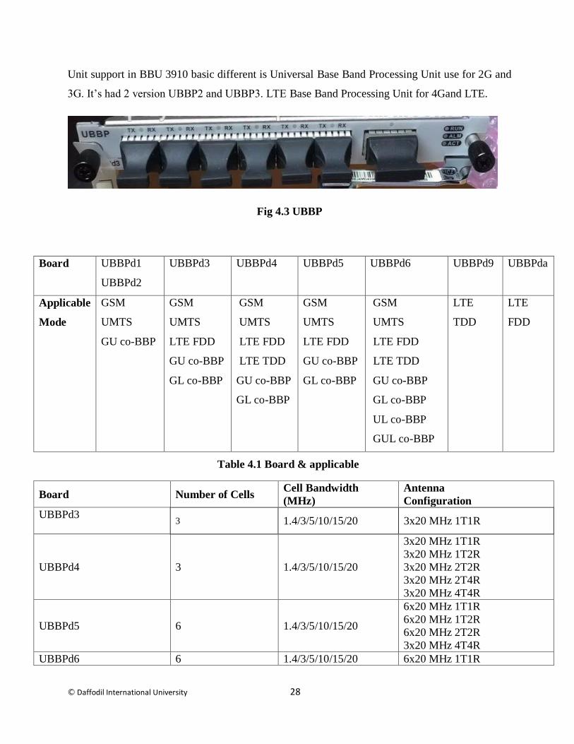
LBBP/UBBP: In the BTS on the BBU found UBBP Universal Base Band Processing Unit or
LBBP LTE Base Band Processing Unit. LBBP LTE Base Band Processing Unit used in BBU
version 3900 it’s had 3 version LBBPa, LBBPb, and LBBPc. Universal Base Band Processing
© Daffodil International University 28
Unit support in BBU 3910 basic different is Universal Base Band Processing Unit use for 2G and
3G. It’s had 2 version UBBP2 and UBBP3. LTE Base Band Processing Unit for 4Gand LTE.
Fig 4.3 UBBP
Board UBBPd1
UBBPd2
UBBPd3 UBBPd4 UBBPd5 UBBPd6 UBBPd9 UBBPda
Applicable
Mode
GSM
UMTS
GU co-BBP
GSM
UMTS
LTE FDD
GU co-BBP
GL co-BBP
GSM
UMTS
LTE FDD
LTE TDD
GU co-BBP
GL co-BBP
GSM
UMTS
LTE FDD
GU co-BBP
GL co-BBP
GSM
UMTS
LTE FDD
LTE TDD
GU co-BBP
GL co-BBP
UL co-BBP
GUL co-BBP
LTE
TDD
LTE
FDD
Board Number of Cells Cell Bandwidth
(MHz)
Antenna
Configuration
UBBPd3
3 1.4/3/5/10/15/20 3x20 MHz 1T1R
UBBPd4 3 1.4/3/5/10/15/20
3x20 MHz 1T1R
3x20 MHz 1T2R
3x20 MHz 2T2R
3x20 MHz 2T4R
3x20 MHz 4T4R
UBBPd5 6 1.4/3/5/10/15/20
6x20 MHz 1T1R
6x20 MHz 1T2R
6x20 MHz 2T2R
3x20 MHz 4T4R
UBBPd6 6 1.4/3/5/10/15/20 6x20 MHz 1T1R
Table 4.1 Board & applicable

© Daffodil International University 29
6x20 MHz 1T2R 6x20 MHz 2T2R
6x20 MHz 2T4R
6x20 MHz 4T4R
UBBPda 6 1.4/3/5/10/15/20
6x10 MHz 2T4R
6x20 MHz 1T1R
6x20 MHz 1T2R
6x20 MHz 2T2R
UMPT: In the BTS on the BBU found UMPT Universal Main processing and transmission unit.
Its functions are:
1) UMPT dealing with signal processing, monitoring performance, management of
equipment and active switchover.
2) Gives clock reference, transmission ports, and the support interface associating with the
OMC. The OMC can be the LMT or M2000 customer.
3) It’s a universal transmitter transmit all kind of network like 2G, 3G, 4G.
Table 4.2 Cell specifications of a UBBP
Working principle of a UBBP
Fig 4.4 UMPT

© Daffodil International University 30
UPEU: In BTS on the BBU found UPEU Universal Power and Environment interface unit card.
It’s a basically power card. Main function is:
1) Its convert input power at -48v to protect the BTS equipment. Minus power don’t harm
the equipment. Its protect from thundering
2) It takes EMUB call data through RS485 sequential correspondence and changes over.
Fig 4.5 UPEU
WMPT: In the BTS on BBU found at slots3 WMPT Main Processes and Transmission unit card.
This card only use for 3G GSM cellular network. It’s transmit and processes the signal. This card
also provide control and management unit for 3G. It’s have USB port to software upgrade and
data configuration. Card consist of ATM and IP protocols and Provides the reference clock. Offer
monitoring performance, configuration management, equipment management, signaling
processing.
Fig 4.6 WMPT

© Daffodil International University 31
GMPT: In the BTS on BBU found GMPT card. It’s a 2G Transmission card. Its install in BBU
5th
card slots. Offer monitoring performance for 2G. configuration management for 2G.
equipment management for 2G, signaling processing for 2G.
Fig 4.7 GMPT Card
BBU comprises of GPS sensors or gadget which track the BBU introduced area and if BBU is
stolen or burglary the GPS arrange is followed and send back to telecom administrator control
room.
There are numerous BBU models made by different telecom administrators. The best 5 telecom
gear producer are Ericsson, Alcatel-Lucent, Huawei Technologies, Cisco Systems and ZTE
Corporation. These sellers have their own kind sort BBU demonstrate however the fundamental
learning is same. The distinctive is that of their capacity proficiency and preparing and working
pace.
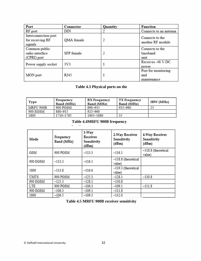
4.3.3 MRFU
The MRFU 900B can be used in an indoor cabinet or a protective outdoor cabinet. RF signal can
be modulate help of MRFU. RF signal can be demodulate with MFRU. Combine two RF signal
and can divide. It’s had Software Defined Radio (SDR) technology that processes baseband and
RF signal. Install in BTS cabinet with side of BBU.
Fig 4.8 MRFU
© Daffodil International University 32
Table 4.3 Physical ports on the
MRFU 900B
Table 4.5 MRFU 900B receiver sensitivity
Table 4.4MRFU 900B frequency
band
© Daffodil International University 33
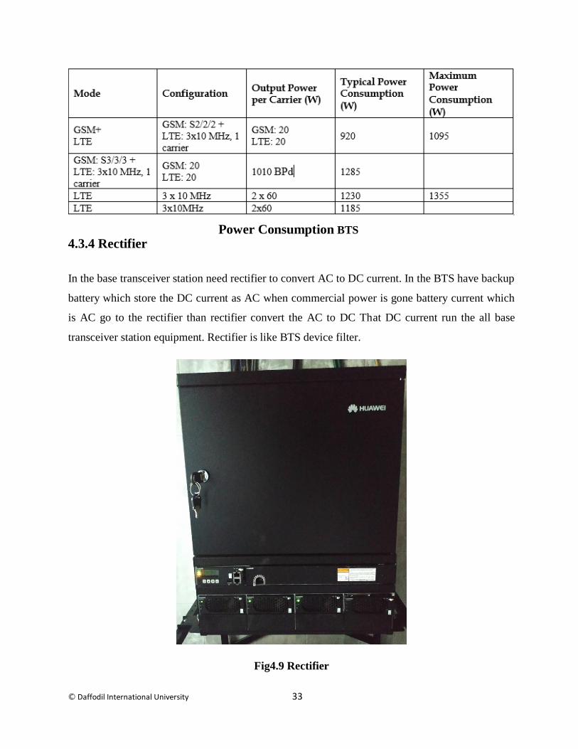
4.3.4 Rectifier
In the base transceiver station need rectifier to convert AC to DC current. In the BTS have backup
battery which store the DC current as AC when commercial power is gone battery current which
is AC go to the rectifier than rectifier convert the AC to DC That DC current run the all base
transceiver station equipment. Rectifier is like BTS device filter.
Fig4.9 Rectifier
Power Consumption BTS
© Daffodil International University 34
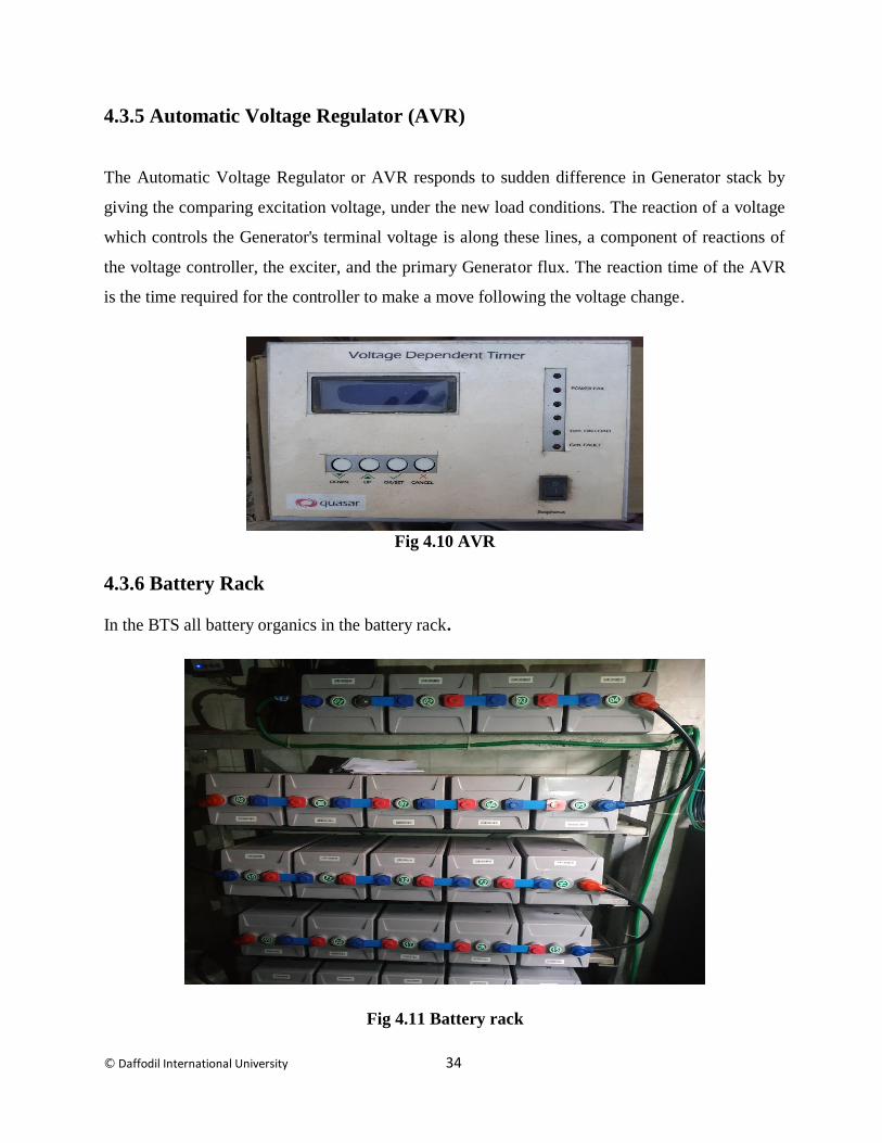
4.3.5 Automatic Voltage Regulator (AVR)
The Automatic Voltage Regulator or AVR responds to sudden difference in Generator stack by
giving the comparing excitation voltage, under the new load conditions. The reaction of a voltage
which controls the Generator's terminal voltage is along these lines, a component of reactions of
the voltage controller, the exciter, and the primary Generator flux. The reaction time of the AVR
is the time required for the controller to make a move following the voltage change.
Fig 4.10 AVR
4.3.6 Battery Rack
In the BTS all battery organics in the battery rack.
Fig 4.11 Battery rack
© Daffodil International University 35
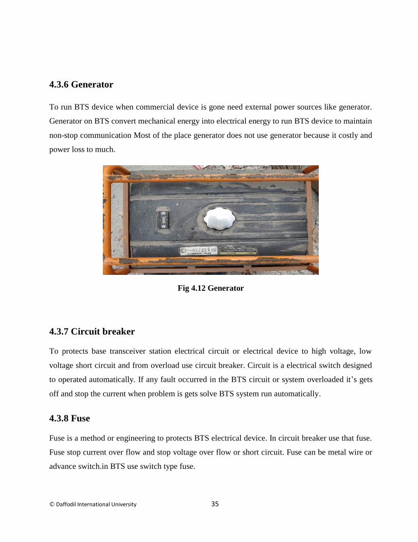
4.3.6 Generator
To run BTS device when commercial device is gone need external power sources like generator.
Generator on BTS convert mechanical energy into electrical energy to run BTS device to maintain
non-stop communication Most of the place generator does not use generator because it costly and
power loss to much.
Fig 4.12 Generator
4.3.7 Circuit breaker
To protects base transceiver station electrical circuit or electrical device to high voltage, low
voltage short circuit and from overload use circuit breaker. Circuit is a electrical switch designed
to operated automatically. If any fault occurred in the BTS circuit or system overloaded it’s gets
off and stop the current when problem is gets solve BTS system run automatically.
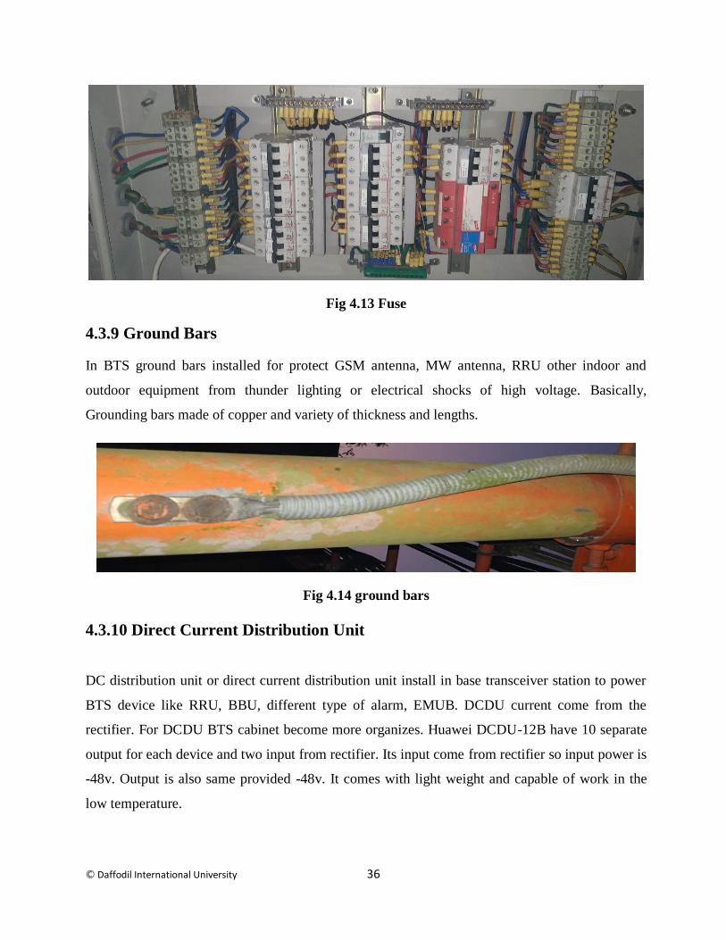
4.3.8 Fuse
Fuse is a method or engineering to protects BTS electrical device. In circuit breaker use that fuse.
Fuse stop current over flow and stop voltage over flow or short circuit. Fuse can be metal wire or
advance switch.in BTS use switch type fuse.
© Daffodil International University 36
Fig 4.13 Fuse
4.3.9 Ground Bars
In BTS ground bars installed for protect GSM antenna, MW antenna, RRU other indoor and
outdoor equipment from thunder lighting or electrical shocks of high voltage. Basically,
Grounding bars made of copper and variety of thickness and lengths.
Fig 4.14 ground bars
4.3.10 Direct Current Distribution Unit
DC distribution unit or direct current distribution unit install in base transceiver station to power
BTS device like RRU, BBU, different type of alarm, EMUB. DCDU current come from the
rectifier. For DCDU BTS cabinet become more organizes. Huawei DCDU-12B have 10 separate
output for each device and two input from rectifier. Its input come from rectifier so input power is
-48v. Output is also same provided -48v. It comes with light weight and capable of work in the
low temperature.

© Daffodil International University 37
Fig 4.14 DCDU
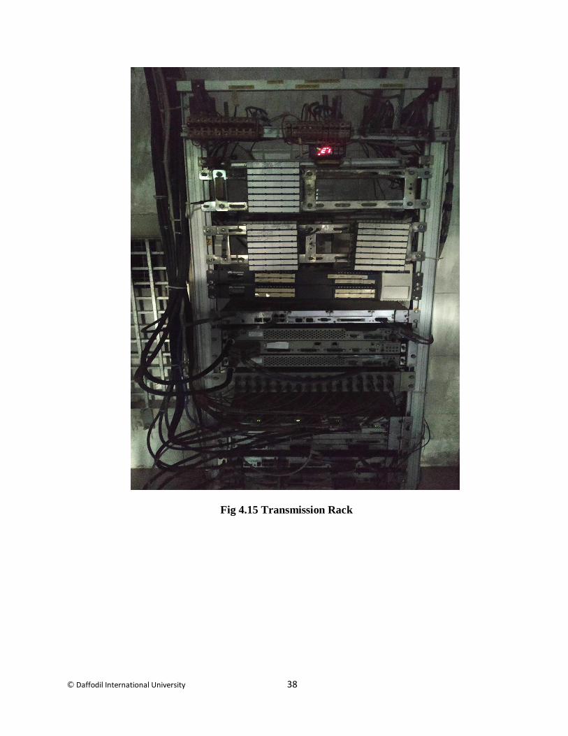
4.4 Transmission Rack
In base transceiver station Transmission rack install to organize transmission device. It’s an
indoor unit like telephone exchanges. This rack build on ETSI standards have the RU or SU
device rails. ETSI follow 19” or 21” rack size.
Features
Have MW antenna transmission unit
BUS BAR GND
Have positive fuse and
The negative fuse.
Various latches to encourage establishment
Variety of extras
© Daffodil International University 38
Fig 4.15 Transmission Rack
© Daffodil International University 39
4.5 Other indoor unit
Smoke Detectors
Door Alarm
Water Sensor
Fire alarm
Temperature Sensor
Cascade Cable
Air-Condition
Ladder
Rox-tec / Feeder Hole
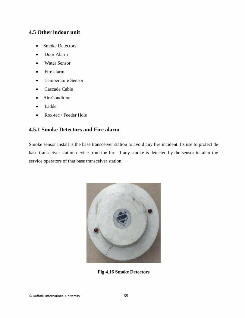
4.5.1 Smoke Detectors and Fire alarm
Smoke sensor install is the base transceiver station to avoid any fire incident. Its use to protect de
base transceiver station device from the fire. If any smoke is detected by the sensor its alert the
service operators of that base transceiver station.
Fig 4.16 Smoke Detectors
© Daffodil International University 40
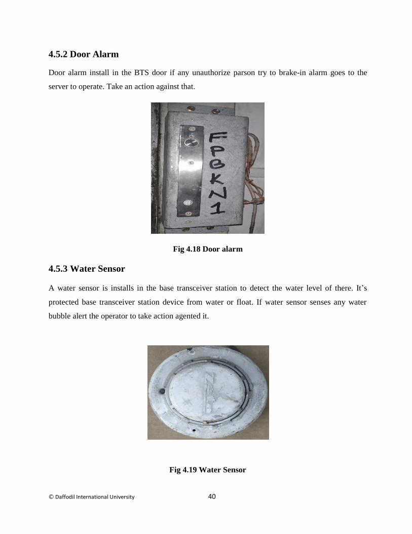
4.5.2 Door Alarm
Door alarm install in the BTS door if any unauthorize parson try to brake-in alarm goes to the
server to operate. Take an action against that.
Fig 4.18 Door alarm
4.5.3 Water Sensor
A water sensor is installs in the base transceiver station to detect the water level of there. It’s
protected base transceiver station device from water or float. If water sensor senses any water
bubble alert the operator to take action agented it.
Fig 4.19 Water Sensor
© Daffodil International University 41
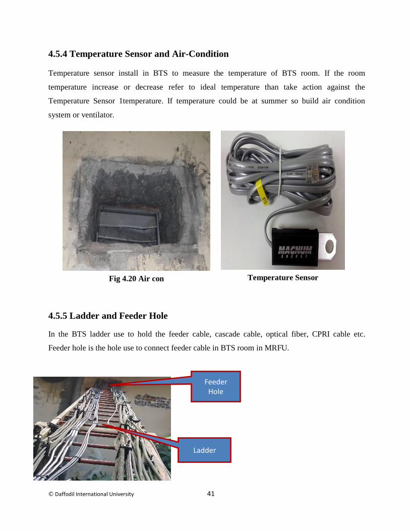
4.5.4 Temperature Sensor and Air-Condition
Temperature sensor install in BTS to measure the temperature of BTS room. If the room
temperature increase or decrease refer to ideal temperature than take action against the
Temperature Sensor 1temperature. If temperature could be at summer so build air condition
system or ventilator.
4.5.5 Ladder and Feeder Hole
In the BTS ladder use to hold the feeder cable, cascade cable, optical fiber, CPRI cable etc.
Feeder hole is the hole use to connect feeder cable in BTS room in MRFU.
Feeder Hole
Ladder
Temperature Sensor Fig 4.20 Air con

© Daffodil International University 42
4.6 Outdoor Equipment
Outdoor equipment installs in the outside BTS tower Like:
RRU
GSM Antenna
Microwave Antenna
Feeder Cable (½ super flex 10m,½ Flex 28m,7/8 Flex 78m,15/8 flex 96m)
CPRI Cable
Connector
Thundering Arrestor
Grounding Bar
4.6.1 RRU
RRU is install in the outdoor unit of the base transceiver station to interaction between user
and operator and distributed integrated frequency unit. It’s full from radio remote unit is
Radio Remote Unit. For 4G have to use RRU 1800. Radio Remote Unit call take capacity
mush higher then MRFU almost twice. RRU take call through GSM antenna which is
connected with RRU by ½ Feeder cable also known as short jumper. The EM received signal
can be process and control by RRU. Then RRU connected with BBU by the CPRI cable
(optical fiber).
Fig 4. 21 RRU

© Daffodil International University 43
4.6.2 GSM Antenna
Most important equipment of outdoor BTS is GSM antenna it’s come with different types of band
of frequency like 850 and 900 for 2G,1800 for 4G and 2100 for 3G. It’s an omnidirectional
antenna. Cover fix area. GSM antenna connect with RRU by short jumper ½ feeder flex cable or
with MRFU by 7/8 or 15/8 feeder cable. It’s come with single band, dual band and tri band for 4G
batter use tri band GSM antenna. Without GSM antenna can’t think about GSM architecture. 2G
to 4G use GSM antenna
Fig4.22 GSM Antenna
4.6.3 Microwave Antenna
After install Base transceiver station have link with to connect others Base transceiver station to
inter the network. That can be done with two way one is microwave or optical fiber link. To
Microwave link have install MW antenna in outdoor unit in the Base transceiver station. It’s have
been short distance and no objective should be allowed between two MW antenna. Kind of line of
side communication.

© Daffodil International University 44
Fig 4.23 MW antenna
MW have 2 unit
Indoor: Indoor unit do MUX or DEMUX process of IF signal
Outdoor: Outdoor unit power the IF signal
Indoor unit and outdoor unit are interconnected by IF cable.
4.6.4 Feeder Cable
Feeder cable use BTS to connection between GSM antenna to MRFU and RRU. It’s had excellent
flexibility. Its camas with this configuration:
1/2 super flex use distant in 10m high basically use into connection between RRU and
GSM antenna.
1/2 Flex use in distant 28m high also use into connection between RRU and GSM
antenna.
7/8 Flex use in distant 78m high use into connection between MRFU and GSM antenna.
15/8 Flex use in distant 96m high use into connection between MRFU and GSM antenna.

© Daffodil International University 45
4.6.5 CPRI Cable
The Common Public Radio Interface (CPRI) is an industry cooperation aimed at defining a
publicly available specification for the key internal interface of radio base stations between the
Radio Equipment Control (REC) and the Radio Equipment (RE). Use to connection between
RRU to BBU.
4.6.6 Connector
There is two type of connector use in BTS technologies in connecting or feeder cable which is:
L type
I type
4.6.7 Thundering Arrestor
A lightning arrester (alternative spelling lightning arrestor) (also called lightning diverter) is a
device used on electric power systems and telecommunication systems to protect the insulation
and conductors of the system from the damaging effects of lightning.
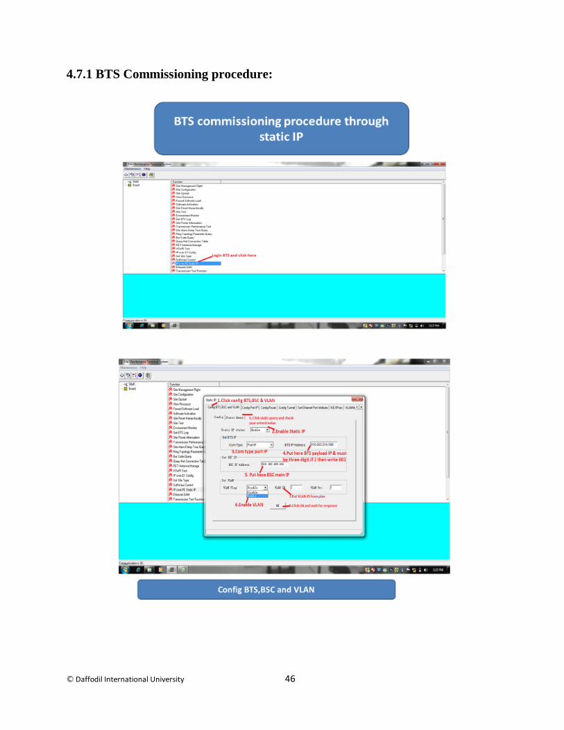
4.7 BTS Commissioning
After the install to all equipment successfully now have to do BTS commissioning part to run
BTS successful.
It is most important part of BTS installation
In this part we have to upload the script in the BTS.
Then service operator active that BTS by server.
L connector
I connector
Fig4.24connector
© Daffodil International University 46
4.7.1 BTS Commissioning procedure:
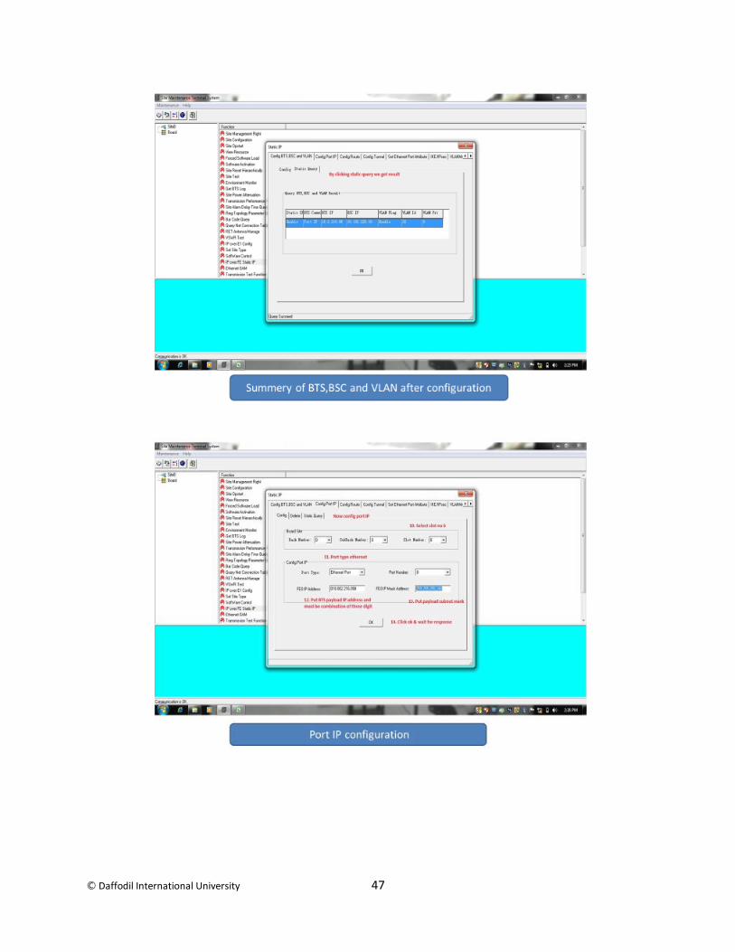
© Daffodil International University 47
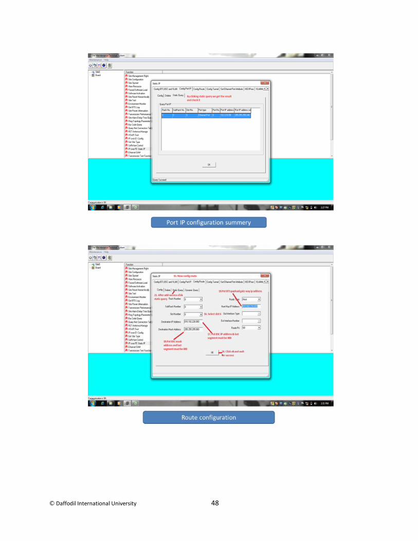
© Daffodil International University 48

© Daffodil International University 49
© Daffodil International University 50
Chapter5
Conclusion
5.1 Conclusion
Working in Starlink Engineering Limited big opportunity me . It’s a first experience of corporate
life. Every day is new experience. Have to go new site every day in full new places. Work we
doing in the company new BTS site, cell splitting etc. Every day known about new kind of BTS
device like GSM antenna, RRU, microwave antenna, BBU. MRFU, rectifier etc.
How they function. How to install dose device in BTS site. How to Commissioning BTS tower.
5.2 Limitation of the work
If the BTS tower in the roof top have get permission from building owner some time we get problem with permission matter.
Same time deal with local people on the site.
I don’t allow to deal with the commissioning part

© Daffodil International University 51
REFERENCE
1. https://en.wikipedia.org/wiki/Cellular_network [Accessed Time: 9:39 PM 12-Dec-18]
2. http://telecombase.blogspot.com/2016/07/bbu-baseband-unit-in-telecom.html[Accessed
Time: 9:40 PM 12-Dec-18]
3. https://edoc.site/rru3908-pdf-free.html[Accessed Time: 9:45 PM 12-Dec-18]
4. http://telecombase.blogspot.com/2016/09/remote-radio-unit-rru-functions-details.html
[Accessed Time: 9:40 PM 12-Dec-18]
5. https://www.electronics-notes.com/articles/connectivity/2g-gsm/network-interfaces.php
[Accessed Time: 9:50 PM 12-Dec-18]
6. https://en.wikipedia.org/wiki/2G [Accessed Time: 9:53 PM 12-Dec-18]
7. https://pdfs.semanticscholar.org/4dfd/40cc3a386573ee861c5329ab4c6711210819.pdf[Access
ed Time: 9:56PM 12-Dec-18]
8. http://www.gyantemple.com/full.php?ID=191 [Accessed Time: 9:59 PM 12-Dec-18]
9. http://www.cathayradio.org/news/newslet_July2015.pdf [Accessed Time: 10:03 PM 12-Dec
18]
10. https://www.mobilemark.com/antenna-solutions/gsm-antennas/gsm-antenna-esign/[Accessed
Time: 10:10 PM 12-Dec-18]
11. http://docplayer.net/2385900-Cellular-network-organization.html [Accessed Time: 10:25 PM
12-Dec-18)
12. http://www.honorcup.ru/upload/iblock/164/2.pdf[Accessed Time: 10:50 PM 12-Dec-18]
13. http://beprojectreport.com/download/E3-AUTOMATIC-WATER-LEVEL-MONITORING-
SYSTEM-USING-GSMTECHNOLOGY.pdf [Accessed Time: 11:01 PM 12-Dec-18]
14. http://telecombase.blogspot.com/2015/12/dcdu-dc-distribution-unit-of-huawei.html
[Accessed Time: 11:25PM 12-Dec-18]
15. https://www.scribd.com/document/230045961/Telecom-concepts [Accessed Time: 11:50 PM
12-Dec-18]
16. https://www.slideshare.net/naveenjakhar12/gsm-base-transceiver-station [Accessed Time:
12:12 PM 12-Dec-18]
17. http://xa.yimg.com/kq/groups/23369832/1949447783/name/project+book2.docx[Accessed
Time: 12:25 PM 12-Dec-18]
18. http://tlclab.unipv.it/downloads/Sistemi%20di%20Trasmissione%20Radio/20080416/06_Sist
emi_radiomobili_cellulari.p [Accessed Time: 01:25 PM 12-Dec-18]
19. https://pt.scribd.com/document/240243228/Huawei-Bts-3900-Training[Accessed Time: 1:50
PM 13-Dec-18]
20. http://docslide.us/documents/3900-series-base-station-technical-description-06pdf-en.html
[Accessed Time: 2:03 PM 13-Dec-18]
21. http://dlibrary.univ-boumerdes.dz:8080/bitstream/123456789/3278/1/MC112015pdf.
[Accessed Time: 2:50 PM 13-Dec-18]
22. http://www.rroij.com/open-access/prepaid-power-billing-using-adaptive-
meter.php?aid=44235 [Accessed Time: 3:50 PM 13-Dec-18]
© Daffodil International University 52
23. https://repository.unikom.ac.id/47216/1/Bab%202%20Cellular%20System.pdf[Accessed
Time: 4:50 PM 13-Dec-18]
24. .http://www.basicelectricalengineering.com/ [Accessed Time: 5:50 PM 13-Dec-18]
25. https://searchmobilecomputing.techtarget.com/definition/4G [Accessed Time: 6:50 PM 13-
Dec-18]
26. http://etheses.saurashtrauniversity.edu/341/1/vandra_kh_thesis_computer%20Engineering1.p
df [Accessed Time: 7:57 PM 13-Dec-18]
27. https://www.coursehero.com/file/19777743/GSMHuwaie/[Accessed Time: 8:54 PM 13-Dec-
18]
28. http://pet.ece.iisc.ernet.in/downloads/uc2008/PDFs/Day14.pdf [Accessed Time: 8:00 AM 15-
Dec-18]
29. https://en.m.wikipedia.org/wiki/Smoke_detector[Accessed Time: 8:30AM 15-Dec-18]
30. http://www.ecpowersystems.com/resources/ground-bars/examination-of-ground-bars-and-
their-purposein-electrical-systems/ [Accessed Time: 9:53 AM 15-Dec-18]
31. http://de.slideshare.net/AchmadFauzi24/huawei-gsm-principles[Accessed Time: 8:00PM 15-
Dec-18]
32. http://docplayer.net/39826471-Openmsc-product-report.html [Accessed Time: 8:30 PM 15-
Dec-18]
33. http://brenclosures.com.au/telecoms_trans.htm[Accessed Time: 9:35 PM 15-Dec-18]
34. http://www.esru.strath.ac.uk/EandE/Web_sites/10-11/Mobile_mast/bts.htm[Accessed Time:
9:56 PM 15-Dec-18]
35. http://www.dieselserviceandsupply.com/How_Generators_Work.aspx [Accessed Time: 10:09
PM 15-Dec-18]
36. https://en.wikipedia.org/wiki/Microwave_antenna (11:50 PM 15-Dec-18)
37. http://www.cinterion.com/m2m-glossary.html(6:00AM 16-Dec-18)
38. http://www.scribd.com/doc/10326000/Putas-Asesinas-Bolanos-Roberto[Accessed Time:
8:00 AM 16-Dec-18]
39. https://www.daenotes.com/electronics/microwave-radar/digital-microwave-communication-
equipment[Accessed Time: 8:50 AM 15-Dec-18]
40. https://wikivisually.com/wiki/TalkTalk_Group[Accessed Time: 6:00 AM 16-Dec-18]
41. http://www.lexproducts.com/specfeed.htm[Accessed Time: 7:30 AM 16-Dec-18]
42. http://www.jbisa.nl/download/?noGzip=1&id=15043720[[Accessed Time: 7:50 AM 16-
Dec-18]
43. http://www.scribd.com/doc/37142214/Ei-Gsm-Ericsson-Bts-At[Accessed Time: 8:05 AM
16-Dec-18]
44. https://www.journalajst.com/sites/default/files/6041.pdf [Accessed Time: 8:50 AM 16-Dec-
18]
45. http://www.randakksblog.com/comprehensive-gl1000-charging-system-
troubleshoot[Accessed Time: 9:00 AM 13-Dec-18]

© Daffodil International University 53
46. http://docslide.us/documents/3900-series-base-station-technical-description-draft-apdf-
en.html[Accessed Time: 9:50 AM 17-Dec-18]
47. https://howlingpixel.com/i-en/3G [Accessed Time: 1:50 PM 17-Dec-18]