eelliittee ll - trp.uk.com l 12 eng.pdf · mulching grass, branches and ... y blade (for cutting...
TRANSCRIPT

INO BREŽICE d.o.o.
8262 Krška vas 34 b, Slovenija
Tel.: ++386 (0) 749 59 233;
Fax: ++ 386 (0) 749 59 151
E-mail: [email protected]
Internet: www.inobrezice.com
FFLLAAIILL MMOOWWEERR
EELLIITTEE LL
OOPPEERRAATTIINNGG IINNSSTTRRUUCCTTIIOONNSS SSPPAARREE PPAARRTTSS LLIISSTT
IITT IISS MMAANNDDAATTOORRYY TTOO RREEAADD AANNDD FFOOLLLLOOWW TTHHEESSEE
IINNSSTTRRUUCCTTIIOONNSS BBEEFFOORREE CCAARRRRYYIINNGG OOUUTT AANNYY
OOPPEERRAATTIIOONN!!

2
CONTENT
1. General information……………………………………………….. 4
Purpose of use………………………………………………………. 5
Warranty...………………………………………………………….. 5
Identification of the machine ……………………………………… 6
2. Technical data ……………………………………………………... 7
Noise ………………………………………………………………… 7
Technical specification …………………………………………….. 8
Optional equipment………………………………………………… 8
3. Safety………………………..………………………………………. 9
General safety rules………………………………………………... 9
Attachment on the tractor and transport.………………………... 10
PTO drive……………………..………………………………….… 11
Hydraulic system...……………………………………………..….. 12
Safety rules during use…………………………………………….. 13
Warning decals…………………………………………………….. 14
List of guards…..…………………………………………………... 15
4. Description and operating of the machine……………………….. 15
5. Transport and attachment of the machine………………………. 17
Transport to the customer.………………………………………... 17
Attachment and detachment from the tractor…………………... 18
Fitting the PTO shaft………………………..…………………….. 19
Stability of the tractor…………………………………………….. 20
6. Adjustment and setting up………………………………………… 21
Regulating the height of cut……………………………………….. 21
Offsetting ………………………………………………………….. 22
Belt tension adjustment……………………………………………. 22
7. Operating….…….…………………………………………………. 23
8. After the job done…………………………………………………. 24
Cleaning……………………………………………………………. 25
9. Maintenance.……………………………………………………….. 26
Belt tension control………………………………………………… 27
Oil level control…………………………………………………….. 28
Greasing…………………………………………………………….. 29
Plan of maintenance jobs……….…………………………………. 30
Replacement of working tools…………………………………….. 31
At the end of the season……………………………………….…… 31
Demolition when out of order…………………………………….. 31
10. Trouble shooting……………………………………...…..……….. 32
11. Spare parts……………………………..………………….……….. 33

3
DDDeeeaaarrr CCCuuussstttooommmeeerrr!!!
WWWeee aaarrreee ggglllaaaddd ttthhhaaattt yyyooouuu dddeeeccciiidddeeeddd tttooo bbbuuuyyy ooouuurrr ppprrroooddduuucccttt ,,, ffflllaaaiii lll mmmooowwweeerrr EEELLLIIITTTEEE LLL... WWWeee
wwwooouuulllddd lll iiikkkeee tttooo ttthhhaaannnkkk yyyooouuu fffooorrr yyyooouuurrr ttt rrruuusss ttt ... WWWeee aaarrreee sssuuurrreee ttthhhaaattt yyyooouuu wwwooonnn ''' ttt bbbeee
dddiiisssaaappppppoooiiinnnttteeeddd wwwiii ttthhh yyyooouuurrr ccchhhoooiiiccceee... AAA qqquuuaaalll iii tttyyy ooofff ttthhheee mmmaaattteeerrr iiiaaalll ,,, aaapppppprrroooppprrr iiiaaattteee ttteeeccchhhnnniiicccaaalll
ccchhhaaarrraaacccttteeerrr iiisssttt iiicccsss aaannnddd aaafff ttteeerrr sssaaallleeesss ssseeerrrvvviiiccceeesss gggooo tttooogggeee ttthhheeerrr wwwiii ttthhh yyyooouuurrr ccchhhoooiiiccceee... FFFooorrr eeevvveeennntttuuuaaalll
qqquuueeesssttt iiiooonnnsss ooouuurrr ssstttuuufff fff iii sss aaalllwwwaaayyysss aaattt yyyooouuurrr dddiiissspppooosssaaalll ...
WWWeee wwwiii lll lll ssspppeeeccciiiaaalll lllyyy rrreeessspppeeecccttt yyyooouuurrr sssuuuggggggeeesssttt iiiooonnnsss aaannnddd ooobbbssseeerrrvvvaaattt iiiooonnnsss ttthhhaaa ttt cccaaannn bbbeee ooofff aaa
gggrrreeeaaattt hhheeelllppp fffooorrr fffuuutttuuurrreee dddeeevvveeelllooopppmmmeeennnttt ooofff ttthhheee mmmaaaccchhhiiinnneee TTThhhrrrooouuuggghhh aaalll lll ttthhheee pppaaasssttt ooofff ooouuurrr
cccooommmpppaaannnyyy eeexxxpppeeerrr iiiaaannnccceeesss fffrrrooommm ttthhheee ppprrraaaxxxiiisss rrreeeppprrreeessseeennnttt aaa bbbaaassseeemmmeeennnttt ooofff dddeeevvveeelllooopppmmmeeennnttt aaannnddd
iiinnnnnnooovvvaaattt iiiooonnnsss...
IIINNNOOO ddd...ooo...ooo...,,, GGGeeennneeerrraaalll MMMaaannnaaagggeeerrr
BBBrrraaannnkkkooo KKKooosss

4
1. General information
This operation and maintenance manual is intented to the operator. It
consists of operating instructions, maintenance part and spare parts list for
the machine.
It is mandatory to follow these instructions in order to prevent events
which could endanger the operator's, other people's and animal's safety,
apart from the correct functioning of the machine. In case of doubt do not
experiment, call INO after-sales service instead, or a specialized INO
dealer.
It is mandatory to read these instructions to understand
the operating of the machine!
In the case of re-sale of the machine it is necessary to give
these instructions to the new owner!
A meaning of decals in this book
Very important information!
Technical warning!
Safety warning!
5
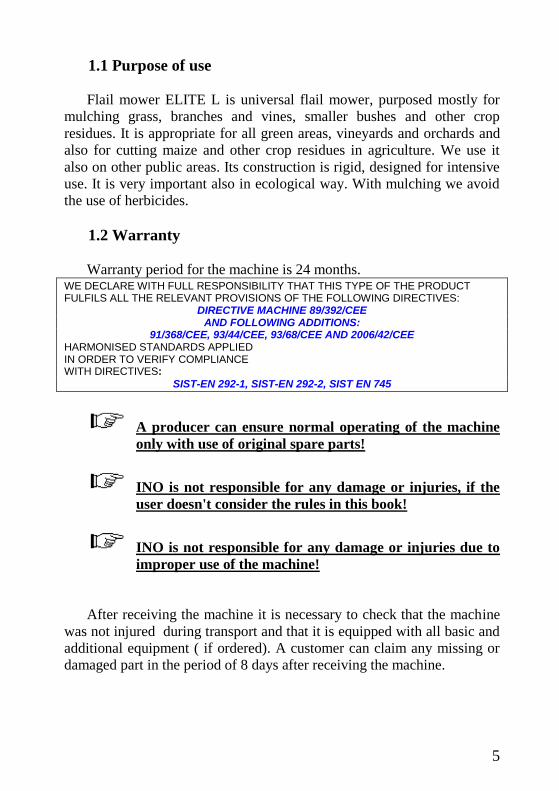
1.1 Purpose of use
Flail mower ELITE L is universal flail mower, purposed mostly for
mulching grass, branches and vines, smaller bushes and other crop
residues. It is appropriate for all green areas, vineyards and orchards and
also for cutting maize and other crop residues in agriculture. We use it
also on other public areas. Its construction is rigid, designed for intensive
use. It is very important also in ecological way. With mulching we avoid
the use of herbicides.
1.2 Warranty
Warranty period for the machine is 24 months. WE DECLARE WITH FULL RESPONSIBILITY THAT THIS TYPE OF THE PRODUCT FULFILS ALL THE RELEVANT PROVISIONS OF THE FOLLOWING DIRECTIVES:
DIRECTIVE MACHINE 89/392/CEE AND FOLLOWING ADDITIONS:
91/368/CEE, 93/44/CEE, 93/68/CEE AND 2006/42/CEE HARMONISED STANDARDS APPLIED IN ORDER TO VERIFY COMPLIANCE WITH DIRECTIVES:
SIST-EN 292-1, SIST-EN 292-2, SIST EN 745
A producer can ensure normal operating of the machine
only with use of original spare parts!
INO is not responsible for any damage or injuries, if the
user doesn't consider the rules in this book!
INO is not responsible for any damage or injuries due to
improper use of the machine!
After receiving the machine it is necessary to check that the machine
was not injured during transport and that it is equipped with all basic and
additional equipment ( if ordered). A customer can claim any missing or
damaged part in the period of 8 days after receiving the machine.

6
INO does not accept any responsibility in the case of:
Improper maneuvring the machine,
Improper maintenance,
Unauthorized repairing or modifications on the machine or
use of non-genuine spare parts,
Non-respecting these rules,
Overloading of the machine (see Table nr.1 – limited values)
1.3 Identification of the machine
Each machine is fitted with an identification plate with the following
data: producer and address, CE sign, name of the machine, type, weight,
identification number and year of production.
Fig. 1
MULČER
ELITE L 190
385 kg
2005 123

7
2 Technical data
Fig. 2
1. frame
2. gear box
3. belt drive
4. 3-point linkage
5. rear roller
6. support foot
7. skid
8. sliding tubes
2.1 Noise
The sound level of this machine, as measured at the operator's ear,
ranges from 70 to 90 dB when the rear window of tractor is open. We
recommend the use of ear protectors
4 6
7
1 5
3
2 7
4
8
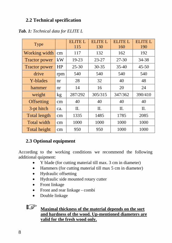
2.2 Technical specification
Tab. 1: Technical data for ELITE L
Type ELITE L
115
ELITE L
130
ELITE L
160
ELITE L
190
Working width cm 117 132 162 192
Tractor power kW 19-23 23-27 27-30 34-38
Tractor power HP 25-30 30-35 35-40 45-50
drive rpm 540 540 540 540
Y-blades nr 28 32 40 48
hammer nr 14 16 20 24
weight kg 287/292 305/315 347/362 390/410
Offsetting cm 40 40 40 40
3-pt hitch ca. II. II. II. II.
Total length cm 1335 1485 1785 2085
Total width cm 1000 1000 1000 1000
Total height cm 950 950 1000 1000
2.3 Optional equipment
According to the working conditions we recommend the following
additional quipment:
Y blade (for cutting material till max. 3 cm in diameter)
Hammers (for cutting material till max 5 cm in diameter)
Hydraulic offsetting
Hydraulic side mounted rotary cutter
Front linkage
Front and rear linkage - combi
Double linkage
Maximal thickness of the material depends on the sort
and hardness of the wood. Up-mentioned diameters are
valid for the fresh wood only.

9
3. Safety
3.1 General safety rules
1. Before starting, checks on the tractor and the machine must be
carried out as regards: functionality, road safety, accident
prevention rules.
2. Together with the operating and maintenance rules for the
machine it is necessary to consider general health and security
rules and warnings.
3. Before starting it is mandatory to know everything regarding the
equipment and operating of the machine. Reading instructions
among operating is too late.
4. Security and warning decals on the machine are very important.
Respect them always.
5. Even when using the machine correctly, stones or other objects
may be thrown on a long distance. Therefore nobody must stand
within the danger area. Special attention must be paid when
working near roads or buildings.
6. Use tractor with the cabin.
7. Whenever using public roads, respect traffic rules.
8. Never wear loose or fluttering clothes.
9. Keep the machine clean to avoid fire danger.
10. Before starting check the surrounding area for the likely presence
of children and/or animals.
11. Never carry passengers on the machine.
10
12. At connecting the machine on the tractor put a support foot into
the working position (up). After removal put the support foot into
the standing position (down). Take care about the stability of the
machine when it is removed.
13. Never overload the machine and the tractor. Use the ballast if
necessary.
14. Start the machine only if all guards of the machine are fit on
proper places .
15. It is forbidden to stand in the range of operating of the machine.
16. Do not enter the working zone of the PTO shaft. It is dangerous to
approach the rotating parts of the machine.
17. Keep a safety distance from drive parts outside of the machine
(PTO shaft, hydraulic pipes).
18. Before leaving the tractor with the machine attached disconnect
the tractor, put the machine steadily on the ground (with the
hydraulic lift), apply the hand brake and if the ground is steeply
slooping, wedge the tractor.Take out the starting key.
19. Do not enter the zone between the tractor and the machine. It is
strongly forbidden to be in this zone if the tractor is not properly
disconnected, hand brake applied and starting key taken out.
Attachment on the tractor and transport
1. Before attaching the machine on or detaching it of the tractor be
sure that hydraulic lift system is in a neutral position.
2. check that a category of 3-point linkage on the tractor
corresponds to that one on the machine.
3. Be careful! There is a danger of injuries when working near or
with 3-point linkage.
11
4. It is forbidden to be in the zone between the tractor and the
machine while working with the hydraulics.
5. Put the 3-point linkage into the position that moving of the
machine during transport is not possible.
6. During transport secure the lever of hydralic lift to avoid any
unplanned moving the machine.
7. Never leave the tractor cab when the tractor is working.
8. Adjust driving speed to the road conditions.
PTO drive
1. Use only PTO shafts with all guards, as directed by the producer.
2. All guards on PTO shaft must be in good order .
3. Take care that all guards on the PTO shaft are in proper position
during transport or operating. Respect the producer's instructions.
4. The PTO shaft must be assembled or diassambled only with the
engine stopped and the starting key removed.
5. The guards of the PTO shaft must be fixed to the machine and to
the tractor with chains, to prevent rotation.
6. Before starting always check that the speed and the rotational
direction correspond to those on the machine.
7. At some tractors a number of rotations depends on the speed and
a direction of rotating depends on the direction of driving. Take
care about that.
8. Before starting the PTO shaft be sure, that noone is in the danger
area.
12
9. Never try to start the PTO shaft when the tractor engine is
disconnected.
10. It is forbidden to be in the zone of drive axle exit, when it is
engaged.
11. After the drive is disconnected wait that the drive axle stops to
rotate completely. Never approach before it stops.
12. Never carry out maintenance of a machine or tractor whilst the
engine is running. The engine should be switched off and the key
removed.
13. If the PTO shaft is damaged, immediately stop with any
operating.
Hydraulic system (optional equipment)
1. Take care! Hydraulics is under very high pressure.
2. At connecting the pipes on the tractor check that the pressure is
not too low.
3. We recommend that an official service tests the pipes before
operating and than at least ones per year. Damaged or worn pipes
should be replaced immediately with others of the same
specification.
4. at checking pipes it is necessary to wear protection clothes and
gloves to avoid injuries.
5. The oil under high pressure may sweep into the skin causing
serious infections. In this case contact a doctor immediately.
6. Before working on the hydraulic system lower the machine, take
pressure out and stop the tractor.

13
7. Approximate using period of the pipes is 6 years. After that the
pipes should be replaced to avoid any damage.
8. Used oils and greases must be stored and disposed of according to
antipollution rules.
Safety rules during use
1. Never start or continue to work with the machine if the tractor or
the drive axle are engaged
2. Always remove the starting key after you stopped the tractor.
3. Periodically check that bolts and nuts are tighten properly.
4. At maintaining it is sometimes necessary to lift the machine. It is
mandatory to put under the machine an appropriate support to
avoid falling the machine at eventual damage on hydraulics.
5. Use the gloves and appropriate tools at changing sharp parts of
the machine to avoid injuries.
6. Used oils and greases should be removed according to the rules.
7. Always disconnect electric cables on the tractor before any
welding or other operation when using electricity is necessary.
8. Only original spare parts should be installed.

14
Warning decals
1. Always take off previously the machine of
the tractor and read the instructions carefully
before starting servicing and or lubrification
operations.
2. Keep at a safety distance from the machine to
avoid the risk of projection of objects.
3. Never remove the guards while the parts of
the machine are moving. It is dangerous to
injure the hands.
4. Keep at a safety distance from the machine to
avoid the risk of cutting the feet.
5. It is forbidden to mount on the machine
because of the risk of fall.

15
List of guards
Fig. 3
1. PTO shaft shield
2. belt shield
3. warning decals
4. Protecting flaps
4. Description and operating of the machine
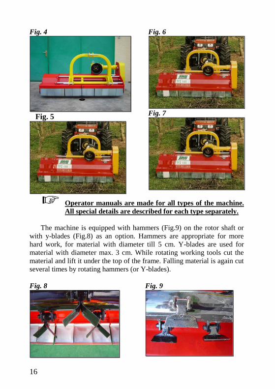
Standard machine is rear mounted. As an option the machines can be
also front mounted (Fig.4), rear and front mounted (fig.5) and rear and
front mounted with 2-linkages (Fig.6).
Optionally a side mounted rotary cutter can be mounted on one or
both sides of the machine.(Fig.7).
1
3
2 4 2
16
Fig. 4
Fig. 5
Fig. 6
Fig. 7
Operator manuals are made for all types of the machine.
All special details are described for each type separately.
The machine is equipped with hammers (Fig.9) on the rotor shaft or
with y-blades (Fig.8) as an option. Hammers are appropriate for more
hard work, for material with diameter till 5 cm. Y-blades are used for
material with diameter max. 3 cm. While rotating working tools cut the
material and lift it under the top of the frame. Falling material is again cut
several times by rotating hammers (or Y-blades).
Fig. 8
Fig. 9
17
Fig. 10
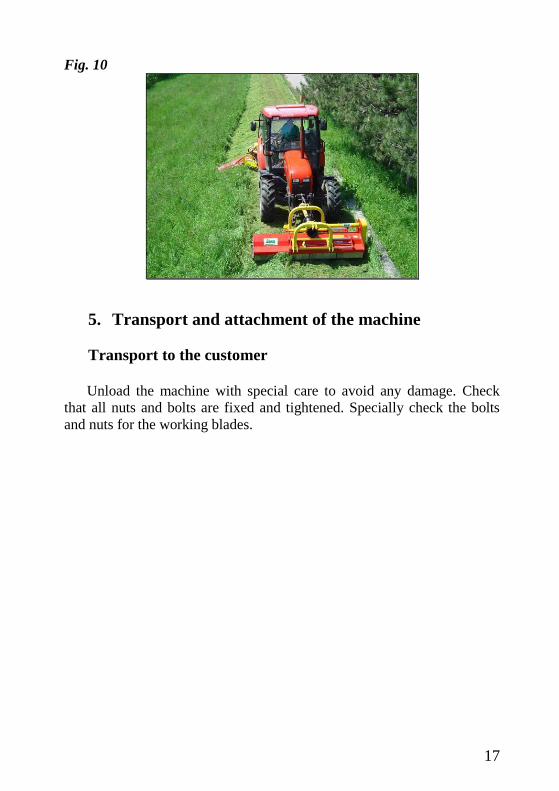
5. Transport and attachment of the machine
Transport to the customer
Unload the machine with special care to avoid any damage. Check
that all nuts and bolts are fixed and tightened. Specially check the bolts
and nuts for the working blades.
18
5.2. Attachment and detachment from the tractor
Before any operation check:
That the machine is in good condition,
That all guards are on proper places and in good condition,
That working blades are complete and undamaged,
That all greasing points are greased well and that in gearbox
is oil enough,
Appropriate tensioned belts,
That rpm and direction of rotation on the drive axle
correspond to those on the machine.
To attack the machine to the tractor, bring the tractor lower lines near
the machine, to the points corresponding to the pins. Insert the pins and
secure them with the spring clips. Fit the top link, raise the machine to a
perpendicular position with the ground. Adjust the two tractor lower
linkage stabilizers thus fixing the machine to the tractor in a central
position. Connect the hydraulic cylinders and check if it works.
3-point hitch of the machine must be in a simetrical
position with the tractor.
At the machine attached put the support foot in a
transport position.
Top linkage point has two working modes: floating (Fig. 12/1) and
fixed linkage (Fig. 12/2). Use floating position whenever working on
hilly, uneven terrain to avoid damaging the machine or linkage.

19
Fig.12
It is mandatory to use floating linkage on hilly or sloping
terrain!
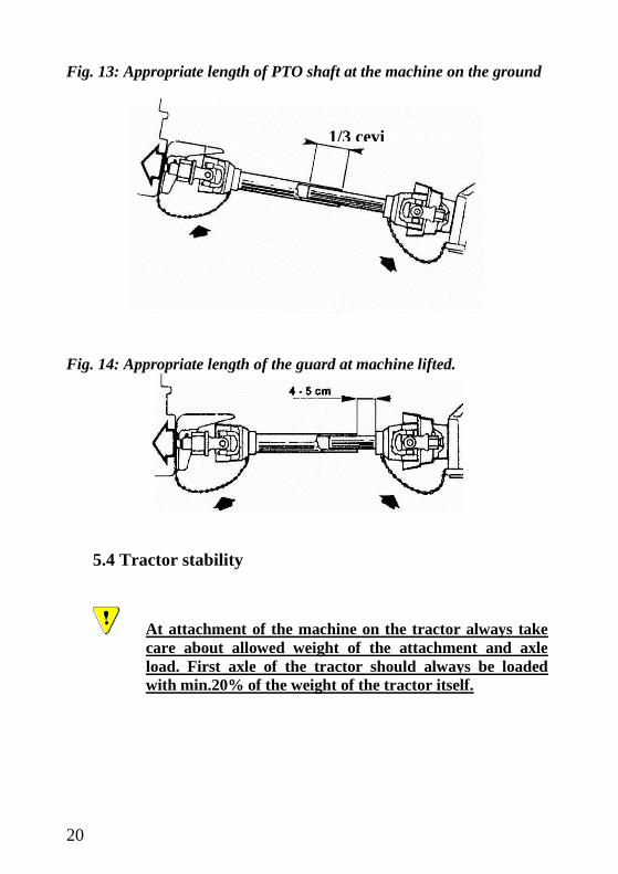
5.3 Fitting the PTO shaft
Attack the machine on the tractor. Split the tubes into both parts and
put one part on the tractor and another on the machine. At the machine
laying on the ground, minimum overlapping of the tubes mustn't be less
than 1/3 of total length. Cut too long part of the tube and clean the edges.
Cut on the proper length also the guard as on fig. 14. Measure the length
when the PTO shaft is in horisontal position. Grease before putting them
together.
Too long PTO shaft can seriously damage tractor or flail
mower.
Never put PTO shaft on the tractor without all guards.
2
1
20
Fig. 13: Appropriate length of PTO shaft at the machine on the ground
Fig. 14: Appropriate length of the guard at machine lifted.
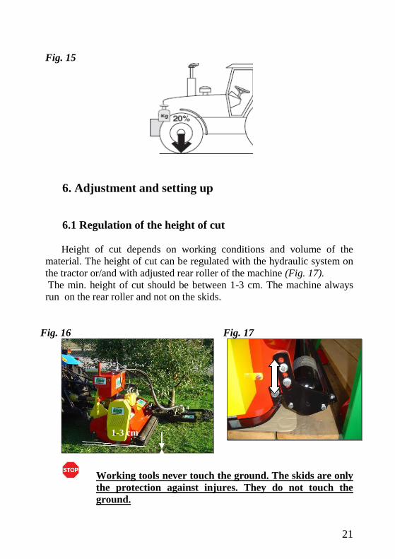
5.4 Tractor stability
At attachment of the machine on the tractor always take
care about allowed weight of the attachment and axle
load. First axle of the tractor should always be loaded
with min.20% of the weight of the tractor itself.
1/3 cevi
21
Fig. 15
6. Adjustment and setting up
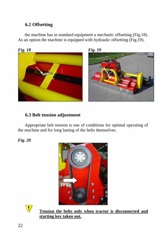
6.1 Regulation of the height of cut
Height of cut depends on working conditions and volume of the
material. The height of cut can be regulated with the hydraulic system on
the tractor or/and with adjusted rear roller of the machine (Fig. 17).
The min. height of cut should be between 1-3 cm. The machine always
run on the rear roller and not on the skids.
Fig. 16
Fig. 17
Working tools never touch the ground. The skids are only
the protection against injures. They do not touch the
ground.
1-3 cm
22
6.2 Offsetting
the machine has in standard equipment a mechanic offsetting (Fig.18).
As an option the machine is equipped with hydraulic offsetting (Fig.19).
Fig. 18
Fig. 19
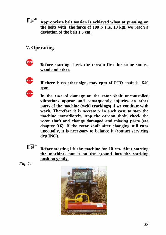
6.3 Belt tension adjustment
Appropriate belt tension is one of conditions for optimal operating of
the machine and for long lasting of the belts themselves.
Fig. 20
Tension the belts only when tractor is disconnected and
starting key taken out.
10 kg
23
Appropriate belt tension is achieved when at pressing on
the belts with the force of 100 N (i.e. 10 kg), we reach a
deviation of the belt 1,5 cm!
7. Operating
Before starting check the terrain first for some stones,
wood and other.
If there is no other sign, max rpm of PTO shaft is 540
rpm.
In the case of damage on the rotor shaft uncontrolled
vibrations appear and consequently injuries on other
parts of the machine (weld crackings) if we continue with
work. Therefore it is necessary in such case to stop the
machine immediately, stop the cardan shaft, check the
rotor shaft and change damaged and missing parts (see
chapter 9.6). If the rotor shaft after changing still runs
unequally, it is necessary to balance it (contact servicing
dep.INO).
Before starting lift the machine for 10 cm. After starting
the machine, put it on the ground into the working
position gently.
Fig. 21
24
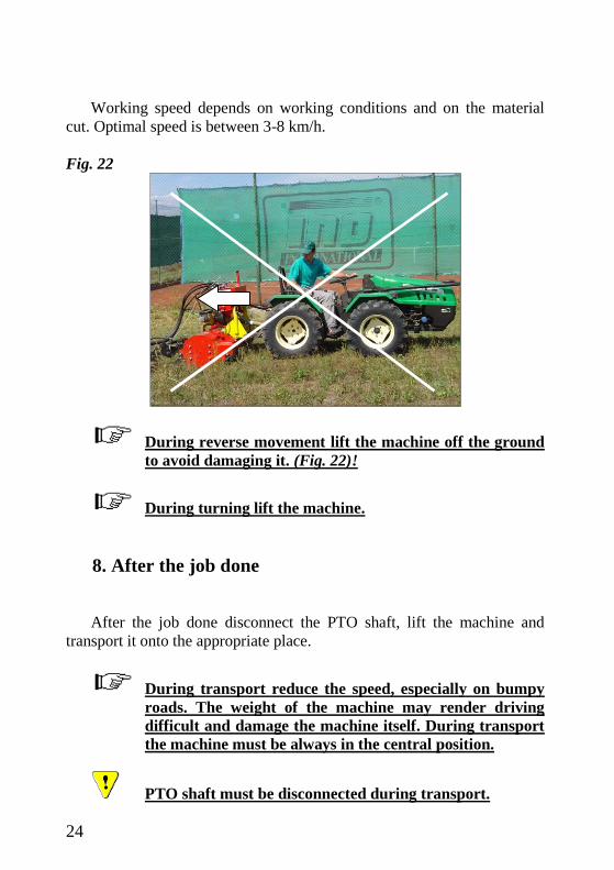
Working speed depends on working conditions and on the material
cut. Optimal speed is between 3-8 km/h.
Fig. 22
During reverse movement lift the machine off the ground
to avoid damaging it. (Fig. 22)!
During turning lift the machine.
8. After the job done
After the job done disconnect the PTO shaft, lift the machine and
transport it onto the appropriate place.
During transport reduce the speed, especially on bumpy
roads. The weight of the machine may render driving
difficult and damage the machine itself. During transport
the machine must be always in the central position.
PTO shaft must be disconnected during transport.

25
At disconnecting the machine respect the warning rules
for connecting the machine.
Check the condition of the rotor shaft, working blades and if
they are tightened well (nuts, washers).
Put the machine on the flat not soft ground. Put the support foot into
the appropriate position. (Fig. 23).To avoid a corrosion store the machine
on a dry place.
Fig. 23
At disconnecting the machine from the tractor block the
rear roller with a piece of wood for stability of the
machine.
8.1 Cleaning
To avoid any corrosion clean the machine after each working day,
especially working tools, bearings etc. Be careful to avoid damaging
hydraulic pipes, bearings and colour.
26
Fig. 24
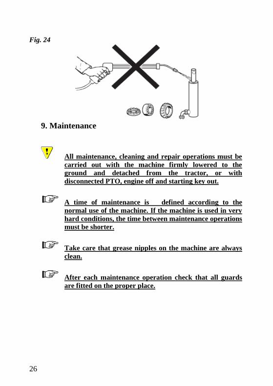
9. Maintenance
All maintenance, cleaning and repair operations must be
carried out with the machine firmly lowered to the
ground and detached from the tractor, or with
disconnected PTO, engine off and starting key out.
A time of maintenance is defined according to the
normal use of the machine. If the machine is used in very
hard conditions, the time between maintenance operations
must be shorter.
Take care that grease nipples on the machine are always
clean.
After each maintenance operation check that all guards
are fitted on the proper place.

27
9.1. Belt tension adjustment
Remove the belt shield (Fig. 27) and check the belt tension. To
tension the belts, loose the nut on the bolt (Fig. 25/1), the bolt (Fig. 25/3)
and four bolts under the gearbox (Fig. 26). Tighten the bolt for tensioning
(Fig. 25/1), the nut and the bolts under gearbox. Put the belt shield back
on the machine.
Fig. 25
Fig. 26
Fig.27
Appropriate belt tension is achieved when at pressing on
the belts with the force of 100 N (i.e. 10 kg), we reach a
deviation of the belt 1,5 cm.
After first two hours of work check the belt tension and if
necessary tighten the taper lock (Fig. 27/1, 2)!
1
1 2
2 3

28
9.2. Oil level control
Use always the same type of oil, SAE 90. For gearbox we need cca 2 l of
oil.Use the hole on the top of gearbox for filling in (Fig. 28/1) and on the
top of the half axle (Fig.28/2 ). For pouring in use a funnel. Pour in the
oil till the level of the control plug on the gearbox and on the half axle.
(Fig.28/3). A plug for oil control is placed under the PVC shield for PTO
shaft on the gearbox. At changing oil unscrew the plug under the gearbox
and let the oil off (Fig. 29/2).
Fig. 28
Fig. 29
1
2
3
1
29
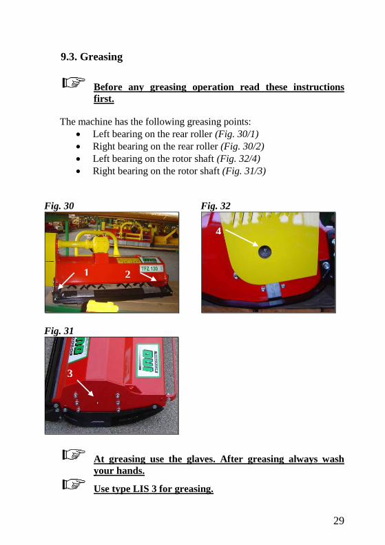
9.3. Greasing
Before any greasing operation read these instructions
first.
The machine has the following greasing points:
Left bearing on the rear roller (Fig. 30/1)
Right bearing on the rear roller (Fig. 30/2)
Left bearing on the rotor shaft (Fig. 32/4)
Right bearing on the rotor shaft (Fig. 31/3)
Fig. 30
Fig. 31
Fig. 32
At greasing use the glaves. After greasing always wash
your hands.
Use type LIS 3 for greasing.
3
2 1
4

30
9.4. Plan for maintenance jobs
1. After first two hours of work always:
Check the belt tension
Check if all bolts and taper locks are tightened enough
Do the same also after each belt changing.
2. After every 8 hours always check:
If the nuts are tightened enough,
A wear and condition of working tools,
Belts and taper locks,
A condition of safe guards,
Oil level in the gearbox,
That any foreign parts are not stuck on the rotor shaft,
That the frame and the 3-point hitch are in good condition,
That all parts are greased well.
3. On every 100 hours we recommend to:
Check and grease the PTO shaft
4. On every 12 months we recommend to:
Change the oil in the gearbox and check the belts tension.
31
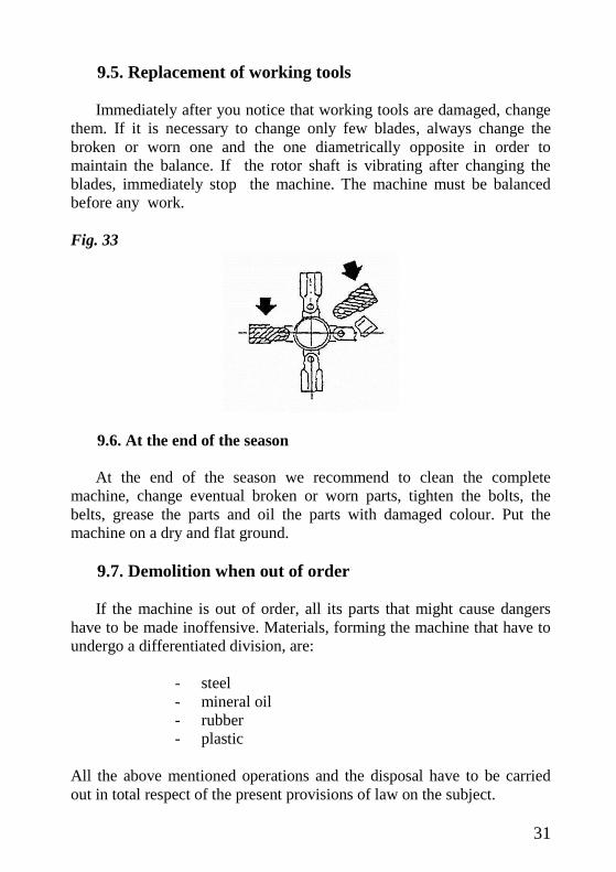
9.5. Replacement of working tools
Immediately after you notice that working tools are damaged, change
them. If it is necessary to change only few blades, always change the
broken or worn one and the one diametrically opposite in order to
maintain the balance. If the rotor shaft is vibrating after changing the
blades, immediately stop the machine. The machine must be balanced
before any work.
Fig. 33
9.6. At the end of the season
At the end of the season we recommend to clean the complete
machine, change eventual broken or worn parts, tighten the bolts, the
belts, grease the parts and oil the parts with damaged colour. Put the
machine on a dry and flat ground.
9.7. Demolition when out of order
If the machine is out of order, all its parts that might cause dangers
have to be made inoffensive. Materials, forming the machine that have to
undergo a differentiated division, are:
- steel
- mineral oil
- rubber
- plastic
All the above mentioned operations and the disposal have to be carried
out in total respect of the present provisions of law on the subject.
32
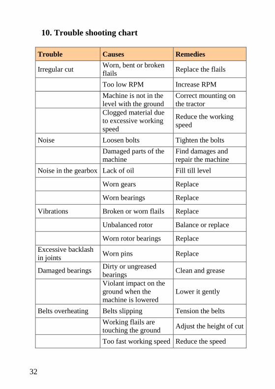
10. Trouble shooting chart
Trouble Causes Remedies
Irregular cut Worn, bent or broken
flails Replace the flails
Too low RPM Increase RPM
Machine is not in the
level with the ground
Correct mounting on
the tractor
Clogged material due
to excessive working
speed
Reduce the working
speed
Noise Loosen bolts Tighten the bolts
Damaged parts of the
machine
Find damages and
repair the machine
Noise in the gearbox Lack of oil Fill till level
Worn gears Replace
Worn bearings Replace
Vibrations Broken or worn flails Replace
Unbalanced rotor Balance or replace
Worn rotor bearings Replace
Excessive backlash
in joints Worn pins Replace
Damaged bearings Dirty or ungreased
bearings Clean and grease
Violant impact on the
ground when the
machine is lowered
Lower it gently
Belts overheating Belts slipping Tension the belts
Working flails are
touching the ground Adjust the height of cut
Too fast working speed Reduce the speed

33
11. SPARE PARTS
We reserve to modify the technical data and
characteristics of the machines at any moment without
prior notice.
A producer is obliged to supply the spare parts min.7
years after the sael of the machine.
At ordering the spare parts always add the following
details: type of the machine, serial number and year of the
production. All data are on the identification plate. See
the sample order below.
machine type Serial nr year Pos. Part nr name pc
f.mower ELITE L 333 2006 4 010863 gearbox 1
Servicing:
Tel.: ++386 (0)7 49 59 233; (0)7 49 59 306

34
A

35
A
Pos. Name Part nr Quantity
115 130 160 190
A FLAIL MOWER ELITE L nnnn
1 FRAME 115 011749 1
FRAME 130 011750 1
FRAME 160 011751 1
FRAME 190 011752 1
FRAME 190 LEFT H 017703 1
1a FRAME 115 FRONT 010530 1
FRAME 130 FRONT 010532 1
FRAME 160 FRONT 110534 1
FRAME 190 FRONT 110535 1
1b FRAME 115 COMB 010525 1
FRAME 130 COMB 010526 1
FRAME 160 COMB 010527 1
FRAME 190 COMB 010528 1
2a SLIDING TUBE 011685 2 2
SLIDING TUBE 011714 2 2
2b LINKAGE 115-130 011754 1 1
2c LINKAGE 160-225 011755 1 1
2d BUSHING 017356 4 4 4 4
2e SPRING RING fi 47 017471 4 4 4 4
2f HOOK 019024 1 1 1 1
3
3a ROTOR 115 HAMMER 011593 1
ROTOR 115 Y-BLADE 010974 1
ROTOR 130 H 010773 1
ROTOR 130 Y 010975 1
ROTOR 160 H 010987 1
ROTOR 160 Y 011009 1
ROTOR 190 H 010988 1
ROTOR 190 Y 011010 1
4 GEARBOX 311-500 PS 019966 1 1 GEARBOX 311-500 PS-COMB 021214 1 1
GEARBOX 311-615 PS 019967 1 1
36
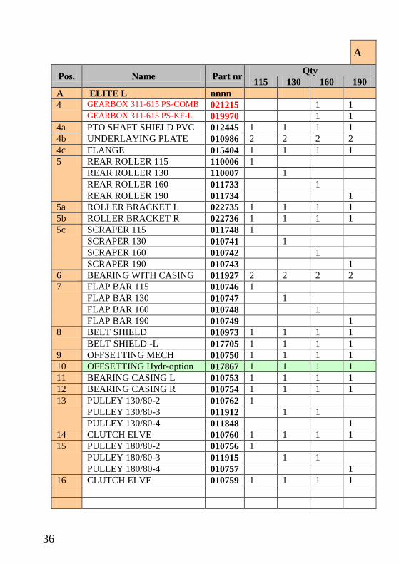
A
Pos. Name Part nr Qty
115 130 160 190
A ELITE L nnnn
4 GEARBOX 311-615 PS-COMB 021215 1 1 GEARBOX 311-615 PS-KF-L 019970 1 1
4a PTO SHAFT SHIELD PVC 012445 1 1 1 1
4b UNDERLAYING PLATE 010986 2 2 2 2
4c FLANGE 015404 1 1 1 1
5 REAR ROLLER 115 110006 1
REAR ROLLER 130 110007 1
REAR ROLLER 160 011733 1
REAR ROLLER 190 011734 1
5a ROLLER BRACKET L 022735 1 1 1 1
5b ROLLER BRACKET R 022736 1 1 1 1
5c SCRAPER 115 011748 1
SCRAPER 130 010741 1
SCRAPER 160 010742 1
SCRAPER 190 010743 1
6 BEARING WITH CASING 011927 2 2 2 2
7 FLAP BAR 115 010746 1
FLAP BAR 130 010747 1
FLAP BAR 160 010748 1
FLAP BAR 190 010749 1
8 BELT SHIELD 010973 1 1 1 1
BELT SHIELD -L 017705 1 1 1 1
9 OFFSETTING MECH 010750 1 1 1 1
10 OFFSETTING Hydr-option 017867 1 1 1 1
11 BEARING CASING L 010753 1 1 1 1
12 BEARING CASING R 010754 1 1 1 1
13 PULLEY 130/80-2 010762 1
PULLEY 130/80-3 011912 1 1
PULLEY 130/80-4 011848 1
14 CLUTCH ELVE 010760 1 1 1 1
15 PULLEY 180/80-2 010756 1
PULLEY 180/80-3 011915 1 1
PULLEY 180/80-4 010757 1
16 CLUTCH ELVE 010759 1 1 1 1

37
A
Pos. Name Part nr Qty
115 130 160 190
A FLAIL MOWER ELITE L nnnn
17 SKID L 015175 1 1 1 1
17 SKID R 015174 1 1 1 1
18 SUPPORT 010846 1 1 1 1
19 OIL WASHER 012241 1 1 1 1
20 PIN fi 8 011598 1 1 1 1
20a PIN fi 14x100 011597 1 1 1 1
21 PIN CONNECT 010991 1 1 1 1
22 PIN CONNECT 011015 2 2
22a PIN CONNECT 010940 2 2
23 PIN fi 10 010328 3 3 3 3
24 PIN R3 010327 2 2 2 2
25 FLAP 140 010769 8 8 11 12
FLAP 130 110008 1 1
FLAP 30 011435 1
FLAP 40 011014 1
FLAP 50 011434 1
FLAP 70 011442 1
26 BLADE Y-OPTION 010867 28 32 40 48
26a HAMMER 011806 14 16 20 24
27 BUSHING Y 012462 14 16 20 24
28 SPACER 010771 56 64 80 96
29 BELT 010447 2 3 3 4
30 BEARING 011054 2 2 2 2
31 SLIDE PC EXT 45 010404 2 2 2 2
32 SLIDE PC INT 100 010417 1 1 1 1
34 BEARING CASING 010934 1 1 1 1
35 BEARING CASING 010935 1 1 1 1
36 BOLT M10x30 010259 1 1 1 1
36a BOLT M10x 65 010264 2 2 2 2
37 BOLT M 8x 16 012024 4 4 4 4
38 BOLT M14x 40 011835 4 4 4 4
39 BOLT M10x 35 010260 4 4 4 4
40 BOLT M12x 30 010998 4 4 4 4
40a BOLT M12x 35 010270 1 1 1 1
41 BOLT M14x 50 011006 1 1 1 1
42 BOLT M14x 35 010325 16 16 16 16

38

39

40
INO BREŽICE d.o.o.
8262 Krška vas 34 b, Slovenija
Tel.: ++386 (0) 749 59 233;
Fax: ++ 386 (0) 749 59 151
E-mail: [email protected]
www.inobrezice.com
V 05/2012