effect of tempering upon the tensile properties of a ... · effect of tempering upon the tensile...
TRANSCRIPT
Effect of tempering upon the tensile properties of a
nanostructured bainitic steel
H.S. Hasana, M.J. Peetb,∗, M-N. Avettand-Fenoelc, H.K.D.H. Bhadeshiab
aUniversity of Technology, Baghdad, IraqbDepartment of Materials Science and Metallurgy, 27 Charles Babbage Road, Cambridge,
CB3 0FS, UKcUnite Materiaux Et Transformations (UMET) UMR CNRS 8207, Universite; Lille 1,
59655 VILLENEUVE D’ASCQ, FRANCE
Abstract
The tensile properties of a nanostructured carbide–free bainitic steel formedat 200–250◦C are compared against those after tempering sufficiently to removethe retained austenite. Although significant ductility is observed following tem-pering, a comparison of tempered and untempered samples shows that it is infact reduced when a comparison is made at identical strength. The shape of thestress-strain curves shows clear evidence that the capacity for work hardening isreduced with the loss of austenite. The nanostructure of the steel transformedat 250◦C is examined by transmission electron microscopy, to compare the as–transformed to the tempered structure. In this case after tempering at 500◦Cthe energy absorbed during the tensile test is lower, due to the lower strength.Reduction of strength is caused by the slight coarsening of the bainite plates,and lower dislocation density after tempering. Considering the formation ofcarbide particles in high strength steel, impressive ductility is exhibited even inthe tempered condition.
Keywords: tempering, tensile properties, nanostructured steel, carbide–freebainite, transformation induced plasticity.
1. Introduction
Strong steels with a nanostructure of bainitic ferrite and austenite can bemanufactured by isothermal transformation from austenite at temperaturesaround 200–250◦C [1]. In these steels the strengthening due to the small sizeof the bainite plates dominates other mechanisms [1, 2]. The transformationby shear [3] at temperatures around 200◦C takes more than one week to reachan asymptotic limiting fraction, or hours at higher temperatures. Careful al-loy design is the only demonstrated method that can be used to accelerate thetransformation while retaining the fine structure [4, 5].
In the earliest work on these steels it was observed that the hardness isrelatively insensitive to quite severe tempering [1], when compared to marten-sitic steels of similar composition. This is because the latter derive most of
∗Corresponding authorEmail address: [email protected] (M.J. Peet)
Preprint submitted to Materials Science and Engineering A July 27, 2014
*Detailed Response to ReviewersClick here to view linked References
Materials Science and Engineering A 615 (2014) 340--347

their strength from interstitial carbon, which on precipitation leads to a largedecrease in hardness. In the case of nanostructured bainite, intense precipita-tion of carbides due to the decomposition of carbon-enriched retained austeniteoccurs at lath boundaries – preventing the ferrite from coarsening and thuspreserving the hardness and strength [6].
The fact that the austenite can decompose on tempering might be a cause forconcern if the steel is to be used at elevated temperatures. Early work demon-strated that when carbide-free microstructures of bainitic ferrite and carbon-enriched austenite are tempered, the decomposition of the austenite, and asso-ciated carbide precipitation, leads to a decrease in toughness [7, 8]. The generalphilosophy is that the austenite helps improve ductility via the classical TRIPeffect, in which the plasticity associated with martensitic transformation helpsdelay the onset of plastic instabilities during tensile testing [9–11]. The motiva-tion for the present work was, therefore, to study the effect of severe temperingon the tensile properties of nanostructured bainite.
2. Methodology
After homogenisation for 48 h at 1200◦C, steel of composition
Fe-0.78C-2.02Mn-1.01Cr-1.6Si-1.37Al-3.83Co-0.25Mo wt%
was transformed at a range of temperatures under vacuum in the Thermecmastor-Z thermomechanical simulator, with which cylindrical samples of 8mm diameterand 12mm in length can be induction heated under vacuum, and then rapidlycooled using inert gas. The temperature is controlled by feedback from anR-type thermocouple, and dimensional changes due to thermal expansion andsolid state phase transformations can be monitored using a laser dilatometer. Aportion of the samples were subjected after transformation to tempering heattreatments in a small tube furnace, and the resultant changes characterised us-ing hardness testing, microscopy and X-ray diffraction. Vickers hardness testsare reported as the average of at least five indentations conducted using a 30 kgload.
Tensile samples with gauge length of 60mm length and 5mm diameter cylin-drical cross section were transformed after austenitisation at 950◦C for 30 min-utes at 200◦C for 3 days, 220◦C for 3 days and 250◦C for 16 h. For directcomparison half of these samples were subjected additionally to tempering at500◦C for 24h. X-ray results (presented later) confirmed that this is sufficientto decompose all retained austenite in the steel. Transformation of the ma-chined tensile samples was achieved by austenitisation at 950◦C in a tube fur-nace purged with a positive pressure of argon gas, before manual transfer to anoven with temperature stability better than 0.1◦C for isothermal transformationat the various temperatures.
Tensile tests were conducted at room temperature using an Instron 2527-111machine with a crosshead speed of 0.1mmmin−1. A strain gauge was attachedto the gauge length with an initial distance between the strain gauge knife edgesof 25mm. The area under the stress–strain curve was integrated to assess thework of fracture.
Fracture surfaces were examined using scanning electron microscopy (Cam-scan MX2600 FEGSEM), and inspection of the cross section of the sample
2

perpendicular to the fracture surface was made using a JEOL 6340 FEGSEMoperated at 15 kV.
X-ray diffraction experiments were conducted using a Philips PW1830 counterdiffractometer with CuKα radiation, at a scan rate of 0.03 ◦ min−1 over therange 35 ≤ 2θ ≤ 105◦ and the system operating at 40kV and 40mA. Rietveldanalysis was applied to fit the whole diffraction pattern using Philips X’PertHighScore plus software, to determine austenite and ferrite phase fractions.
Transmission electron microscopy (TEM) with an accelerating voltage of200kV was also performed on thin foils for the specimen homogenised at 1200◦Cfor 2 days, austenised at 950◦C for 30min under argon and isothermally held at250◦C for 16 h. Thin foils were ground to 50 µm and finally electrochemicallythinned using a Struers Electropol twin jet polishing system to produce anelectron transparent volume. The electrolyte was composed in volume of 5%perchloric acid, 15% glycerol and 80% of methanol. Polishing occurred witha potential of 32V at -34◦C and a current density of 5.7 Amm−2 for the as–transformed bainitic structures. For the specimens tempered at 500◦C for 1 daythe conditions were 22.5V, -17.7◦C.
3. Results
Figure 1 shows the change in hardness with tempering time for samplestransformed at different transformation temperatures (200, 220 and 250◦C) andthen tempered at 500◦C for different times. Based on previous experience, tem-pering for 24 h was estimated to be sufficient to ensure that retained austenitehad decomposed fully [6, 12–14]. X-ray diffraction was used to investigate theaustenite fraction after tempering, finding none present. As seen in the figure,most of the hardness decrease had occurred by 24 h.
There is a marked change in tensile behaviour as a consequence of the tem-pering (Figure 2 and Table 1). Rather than the classical shape of parabolichardening following gradual yielding, linear hardening at a lower rate is ob-served after a distinct yield point until fracture. At the same time the elonga-tion observed is higher in comparison to the as–transformed condition in eachcase. This behaviour was observed regardless of the transformation tempera-ture used. The tensile results for the samples transformed at 250◦C are notable,in that samples before and after tempering both have around 10% elongation.Toughness as measured by the area under the stress–strain curve is reduced,due to the lower tensile strength.
In the as-transformed state the hardness is observed to increase with decreas-ing transformation temperature, while the elongation decreases. Upon temper-ing the hardness values began to converge. Despite this, the tensile propertiesstill had a strong dependence upon the isothermal transformation temperature.
X-ray diffraction patterns were collected from samples before and after tem-pering at 500◦C for 1 day (Figure 3). They show, as expected from the in-crease in driving force as a function of undercooling, that the volume fractionof austenite in the as-transformed samples decreased as the isothermal trans-formation temperature was reduced and show that the tempering reduced theretained austenite to negligible amounts in all cases (Table 2). No austenitepeaks could be distinguished after tempering, considering the isolated austenite(220) peak the lowest fraction of austenite detectable at the 99% confidencelevel is calculated to be 0.04% assuming a peak width of 2 degree 2θ.
3

The larger quantity of austenite associated with the 250◦C sample is con-sistent with its greater ductility in the as-transformed condition. The highercarbon supersaturation of the austenite in this sample is unexpected on the ba-sis of thermodynamic criteria alone; although a similar trend has been observedpreviously [1, 15, 16]. It is clear from Table 2 that Vγxγ+(1−Vγ)xα = x, wherex is the average concentration of carbon in the steel, i.e. 0.79wt%.
These issues can be resolved with the knowledge, consistent with atom-probeobservations, that carbon is not just present in solid solution in the bainitic fer-rite [17, 18] but also located at defects such as dislocations. Such trapped carbonis located at positions where the lattice is already dilated due to the strain fieldof the defect [19]. We assume that the expansion of the lattice parameter asdetected by measuring the lattice parameter using X-ray diffraction, does notaccount for heterogeneous strains due to defects since such defects lead to peakbroadening, but is largely due to carbon in solid solution. It follows that theresidue xρ = x−Vγxγ−(1−Vγ)xα is the trapped carbon, then the data indicatethat the defect density must increase as the transformation temperature is re-duced. This, of course, is exactly as expected since both the dislocation densityand the amount of interfacial area per unit volume increase as the bainite is pro-duced at a lower temperature [20]. Notice that carbon is known to be trappedin defects within both ferrite and austenite, so the values of xρ in Table 2 arenot particularly large. This hypothesis would also explain the larger xγ of thesample transformed at 250◦C, because less carbon is trapped in the defects inits coarser and softer structure, making more available for partitioning into theaustenite. The concept described here, and the concentrations involved, areconsistent with early work [21] that demonstrated quantitatively that high con-centrations of carbon (< 0.45wt%) can be associated with dislocation densitiestypical of lath martensite; the new aspect here is to claim that the segregationof carbon to such defects does not lead to significant lattice expansion.
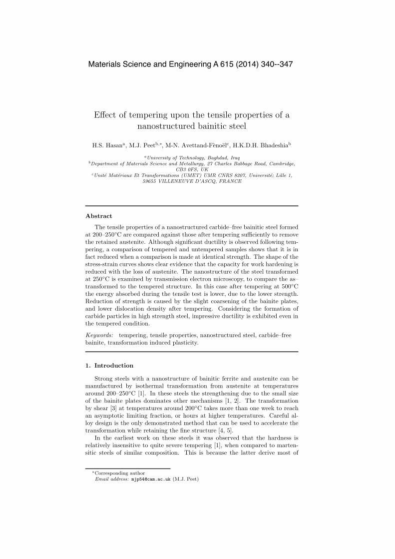
Figure 4 shows the fractographs for the as-transformed samples at differenttransformation temperatures (220, 250◦C) and also after subsequent temperingfor 1 day at 500◦C. The fracture surfaces of the untempered samples consist ofmany microvoids and dimples, with a small amount of intergranular separationat the austenite grain boundaries. The major mechanism of ultimate failure inthe untempered sample is by ductile nucleation and growth of voids, and thefinal shearing of the specimen produces a cup and cone fracture as seen fromFigure 5.
As previously observed, and shown in the transmission electron microscopypresented later, a fine dispersion of carbides results from the decomposition ofretained austenite completely into a mixture of ferrite and carbides during tem-pering. In the tempered samples the dimples observed on the fracture surfaceare much finer, consistent with the presence of many carbides from which voidnucleation can occur. Crack propagation along the grain boundaries is moreprevalent and the major mechanism of ultimate failure is by quasi-cleavage. Inquasi-cleavage, cleavage occurs on a very fine scale between the array of car-bide particles. A fine network of cracks initiates and as the stress increases thecleavage extends by tearing into the ferrite matrix around it by microvoid coa-lescence. This failure mechanism has sufficient toughness to allow the temperedsample to possess a higher elongation than the as–transformed condition as seenin Figure 2. Figure 6 shows the microstructure for the area within 200 µm ofthe fracture surface of the as transformed sample at 250◦C and the tempered
4

sample at 500◦C for 1 day. The plasticity before failure is demonstrated by theexistence of voids just below the fracture surface, and the observation of neckingat the macroscopic scale.
Figure 7 shows the structure of the untempered specimen homogeneised at1200◦C for 2 days, austenised at 950◦C for 30min under argon and isothermallyheld at 250◦C for 16 h. The selected area electron diffraction pattern proves theexistence of bainitic ferrite crystals (two orientations), together with austenitethat is intercalated between the ferrite platelets (Figure 7). The thin plates ofbainitic ferrite are highlighted in figure 7c, which shows an example dark fieldimage taken using the spot indexed as [101]α in Figure 7c.
The influence of tempering is illustrated in Figure 8 with some indications ofbainitic ferrite plate coarsening, as established quantitatively. The mean linearintercept (L
αT ) measured normal to the projected long directions of thin plates
is related to their true thickness as follows [22, 23]:
LαT = πt/2 with the 95% confidence error E = ±2σα
L/(π√N) (1)
where σαL standard deviation of the intercepts, N the number of measurements.
For the specimen isothermally held at 250◦C for 16 h, the true thickness ofthe plates is close to 38±3nm whereas the value is found to be 43±4nm for thesample tempered at 500◦C for 1 day. These values are similar within the confi-dence limits, consistent with previous work [12] that indicated the remarkableresistance of the nanostructure to coarsening.
A comparison of Figures 8a and 8b further shows that instead of austenite atthe interface of the bainitic ferrite plates, some fine carbides have precipitatedduring tempering at 500◦C for 1 day. Accounting for stereology [24, 25] fromthe analysis of 182 precipitates, the volume fraction and the interspacing ofprecipitates were estimated as 2.47% and 60 nm, respectively with a mean radiusof 5.8 nm. These calculations were performed assuming that precipitates are areequiaxed and that the thin foil had a thickness of 50 nm.
4. Discussion
In order to better understand the change in mechanical properties upontempering, calculations were performed to evaluate the strength contributionsto the bainitic ferrite in the material transformed at 250◦C in the as-transformedand tempered condition. The strength in MPa has been expressed in previouswork by equation 2 [26, 27] for 0.4Cwt% alloys. Although this formulation isnot directly applicable to the total strength in this case, especially as it neglectscomposite effects due to a microstructure containing retained austenite, it pro-vides a useful indication of the magnitude of the various strength contributions.
σ = σFe +!
i
σSS,i + σC +115
LαT
+ 7.34× 10⁻⁶√ρD +42
λpMPa (2)
where σFe is the strength of pure annealed iron, σSS,i the solid solution strength-ening due to substitutional solute i and σC the solid solution due to carbon.σSS,i = 84.%Si + 32.%Mn + 13.%Mo - 30.%Cr [28, 29], σC = 1722.5
√%C
where the alloying elements are all in solution in the bainitic ferrite [26]; the
5
concentrations are in wt%. LαT is the mean lineal intercept of bainitic ferrite
plates expressed in µm, ρD the dislocation density in m−2, and λp the distancebetween carbide particles on the slip plane in µm.
Smith and Hehemann [30] studied hardening by cementite precipitation in0.4C-1.8Ni-Cr-Mowt% carbon martensitic steel (AISI 4340). They expressedthe particle strengthening (σp in MPa) in terms of the average distance betweentwo particles on the slip plane (λp). Assuming a cubic distribution they providedthe formulation;
σp =42
λp=
42
r
"
#
2π3f
$1/2%
− π2
MPa (3)
where r is the radius and f is the volume fraction of precipitates.Calculation of the interparticle spacing on the slip plane is necessary for
the formulation applied to particle strengthening; this is different to the trueparticle spacing which can be calculated following Frommeyer [25], also fromthe radius and volume fraction, as 60 nm.
From measurements of precipitate radius of 5.8 nm and using the thermo-dynamically calculated volume fraction of cementite of 0.0025, the predictedcontribution due to precipitate strengthening is 265MPa.
Table 3 summarises the individual strengthening contributions for the spec-imen in two conditions: isothermally held at 250◦C for 16 h, and also subse-quently tempered at 500◦C for 1 day. The purpose is to illustrate the relativemagnitudes of the individual contributions to yield strength, rather than to cal-culate the actual strength in a tensile test. On tempering the small increasein the bainite plate size leads to a proportional decrease in the strength con-tribution. Strength contribution due to other factors is greatly reduced, andpartially compensated for by the addition of precipitate strengthening.
It is noticeable that the strength of the as-transformed material is greatlyoverestimated, assuming that the individual contributions can simply be summed.In reality, similar analyses indicate a power-weighted sum, σk =
&
σik, where k
is essentially a fitting constant [31, 32, e.g.]. If, for example, we choose k ≈ 3,then the strength levels predicted are close to those observed, but the choice ofk is empirical so this approach is not generally recommended at this time.
Secondly, the calculation neglects the presence of austenite; nanoindentationexperiments on nanostructured bainite similar to the present work, and followingtransformation at 250◦C, have demonstrated that the austenite is much weaker[33]. Indeed, the ratio of the hardness of austenite to ferrite was found to be 0.69[33]. Composite theory [34, 35] indicates that because of a stress focusing effect,deformation in such a mixed structure will begin at a stress less than 0.69 of thecalculated strength of the ferrite, i.e. < 0.69× 3249 = 2256MPa. Furthermore,as deformation progresses, the TRIP effect continues to provide a hardeningmechanism until the austenite content loses percolation resulting in fracture[11]. There is nevertheless, a need for further understanding of the deformationbehaviour of such fine structures containing plate-like grains, because it is notclear whether the terms listed in Table 3 are strictly additive. For example, thestrong solid-solution contribution from carbon may override any smaller barriersdue to dislocation forests.
Transformation at 250◦C resulted in a fraction of 0.21 retained austenite, asa result of ductile fracture around 0.1 fraction is expected to remain after the
6
tensile test. As noted in the results section, the difference in strain hardeningwith and without austenite present results in higher total energy absorbed (87−75 = 12MJm−3 or 86 Jmol−1). This value is equivalent to the transformingaustenite absorbing an energy of 782 Jmol−1, a value similar to the stored energyresulting from martensite transformation (usually around 700–1200 Jmol−1).
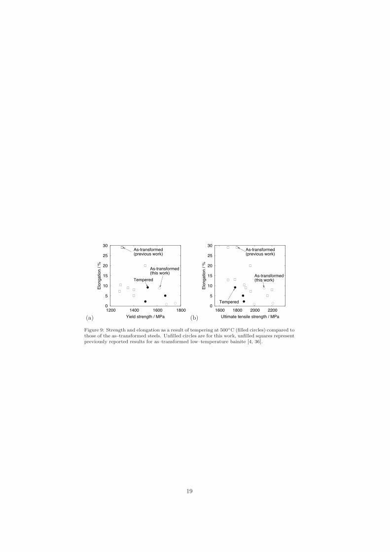
A key difference also is that the strain hardening capacity in the untemperedsamples is clearly greater than after tempering, consistent with the role of re-tained austenite via the TRIP effect. As a consequence, the combinations ofproperties after tempering are not improved in comparison to as–transformednanostructures of the same strength level as demonstrated in Figure 9.
5. Conclusions
The present work shows that tempering of hard–nanostructured–bainiticsteels to remove austenite can result in steels which maintain or have improvedelongation in spite of an intense precipitation of carbides at the plate bound-aries. This comes at the cost of lowering the strength of the steel, just as occursclassically in the tempering of quenched martensitic steels.
After tempering the strength contribution from the scale of the bainite platesbecomes increasingly dominant. Quite severe tempering leads to a removal ofcarbon that has remained in solid solution in the bainitic ferrite, and a recoveryof the structure without significant coarsening of the plates. The contributionto the strength made by the carbide particles is relatively small.
Comparison of the stress–strain curve of as–transformed and tempered nanos-tructure vividly illustrates the benefit of retained austenite in achieving addi-tional strain hardening, with strain hardening resulting from the additionalenergy needed to transform austenite to martensite during deformation.
The observation bodes well for the design of nanostructured steel for useat elevated temperatures. Whilst the retention of austenite has been demon-strated to be beneficial, useful mechanical properties are still possible even upontempering.
6. Acknowledgements
The authors would like to thank Professor A. L. Greer for the provisionof laboratory facilities at the University of Cambridge and also express theirgratitude to the Scholars Rescue Fund of International Institute of Educationin Washington DC, for supporting Hala Salman Hasan’s work in Cambridge.We also thank Dr. Yan Pei and Dr. Lucy Fielding for helpful discussion.
References
[1] F. G. Caballero, H. K. D. H. Bhadeshia, K. J. A. Mawella, D. G. Jones,and P. Brown. Very strong, low–temperature bainite. Materials Scienceand Technology, 18:279–284, 2002.
[2] C. G. Mateo and F. G. Caballero. Ultrahigh–strength bainitic steels. ISIJInternational, 45:1736–1740, 2005.
7

[3] M. Peet and H. K. D. H. Bhadeshia. Surface relief due to bainite transfor-mation at 473 K. Metallurgical & Materials Transactions A, 42:3344–3348,2011.
[4] C. Garcia-Mateo, F. G. Caballero, and H. K. D. H. Bhadeshia. Accelerationof low–temperature bainite. ISIJ International, 43:1821–1825, 2003.
[5] H. S. Hasan, M. Peet, H. K. D. H. Bhadeshia, S. Wood, and E. Watson.Temperature cycling and the rate of the bainite transformation. MaterialsScience and Technology, 26:453–456, 2010.
[6] M. Peet. Transformation and tempering of low–temperature bainite. PhDthesis, University of Cambridge, Cambridge, U. K., 2010.
[7] H. K. D. H. Bhadeshia and D. V. Edmonds. Bainite in silicon steels: a newcomposition property approach I. Metal Science, 17:411–419, 1983.
[8] H. K. D. H. Bhadeshia and D. V. Edmonds. Bainite in silicon steels: a newcomposition property approach II. Metal Science, 17:420–425, 1983.
[9] M. Sherif, C. Garcia-Mateo, T. Sourmail, and H. K. D. H. Bhadeshia.Stability of retained austenite in TRIP–assisted steels. Materials Scienceand Technology, 20:319–322, 2004.
[10] M. Y. Sherif. Characterisation and development of nanostructured, ultra-high strength, and ductile bainitic steels. University of Cambridge, 2005.
[11] H. K. D. H. Bhadeshia. Nanostructured bainite. Proceedings of the RoyalSociety of London A, 466:3–18, 2010.
[12] C. Garcia-Mateo, M. Peet, F. G. Caballero, and H. K. D. H. Bhadeshia.Tempering of a hard mixture of bainitic ferrite and austenite. MaterialsScience and Technology, 20:814–818, 2004.
[13] H. S. Hasan, M. J. Peet, and H. K. D. H. Bhadeshia. Severe temperingof bainite generated at low transformation temperatures. InternationalJournal of Materials Research, 103:1319–1324, 2012.
[14] C. N. Hulme-Smith, I. Lonardelli, M. J. Peet, A. C. Dippel and H. K.D. H. Bhadeshia. Enhanced thermal stability in nanostructured bainiticsteel. Scripta Materialia, 69:191-194, 2013.
[15] C. Garcia-Mateo, F. G. Caballero, and H. K. D. H. Bhadeshia. Low–temperature bainite. Journal de Physique Colloque, 112:285–288, 2003.
[16] C. Garcia-Mateo and F. G. Caballero. Role of retained austenite on tensileproperties of steels with bainitic microstructures. Materials Transactions,46:1839–1846, 2005.
[17] F. G. Caballero, M. K. Miller, C. Garcia-Mateo, and J. Cornide. Newexperimental evidence of the diffusionless transformation nature of bainite.Journal of Alloys and Compounds, 577:S626–S630, 2013.
[18] F. G. Caballero, M. K. Miller, C. Garcia-Mateo, J. Cornide, and M. J.Santofimia. Temperature dependence of carbon supersaturation of ferritein bainitic steels. Scripta Materialia, 67:846–849, 2012.
8

[19] A. Seegar and P. Haasen. Density changes of crystals containing disloca-tions. Philosophical Magazine, 3:470–475, 1958.
[20] H. K. D. H. Bhadeshia. Bainite in Steels, 2nd edition. Institute of Materials,London, U.K., 2001.
[21] D. Kalish and M. Cohen. Structural changes and strengthening in thestrain tempering of martensite. Materials Science and Engineering, 6:156–166, 1970.
[22] L. C. Chang and H. K. D. H. Bhadeshia. Austenite films in bainitic mi-crostructures. Materials Science and Technology, pages 874–881, 1995.
[23] H.K.D.H. Bhadeshia. Introduction to quantitative metallography. Part IIlecture notes, 2013.
[24] J. W. Cahn and J. Nutting. Transmission quantitative metallography.Transations of the Metallurgical Society of AIME, 15:526–528, 1959.
[25] G. Frommeyer. Physical Metallurgy, eds R. W. Cahn and P. Haasen, vol-ume 2. Elsevier, Amsterdam, Holland, 1983.
[26] C. H. Young and H. K. D. H. Bhadeshia. Strength of mixtures of bainiteand martensite. Materials Science and Technology, 10:209–214, 1994.
[27] J. Daigne, M. Guttmann, and J. P. Naylor. Influence of lath boundaries andcarbide distribution on the yield strength of 0.4%C tempered martensiticsteels. Materials Science and Engineering, 56:1–10, 1982.
[28] F. B. Pickering and T. Gladman. Metallurgical developments in carbonsteels. Technical Report Special Report no. 81, Iron and Steel Institute,London, U.K., 1963.
[29] G. R. Speich and H. Warlimont. Yield strength and transformation sub-structure of low carbon martensite. J. Iron and Steel Institute, 206:385–392,1968.
[30] D. W. Smith and R. F. Hehemann. Influence of structural parameters onthe yield strength of tempered martensite and lower bainite. Journal Ironand Steel Institute, 209(6):476–481, 1971.
[31] K. L. Kendig and D. B. Miracle. Strengthening mechanisms of an Al-Mg-Sc-Zr alloy. Acta Materialia, 20:4165–4175, 2002.
[32] S. Schanzer and E. Nembach. The critical resolved shear stress of γ′-strengthened nickel-based superalloys with γ′-volume fractions between0.07 and 0.47. Acta Metall. Mater., 40(4):803–813, 1992.
[33] H. F. Lan, X. H. Liu, and L. X. Du. Ultra–hard bainitic steels processedthrough low temperature heat treatment. Advanced Materials Research,156–157:1708–1712, 2011.
[34] Y. Tomota, K. Kuroki, T. Mori, and I. Tamura. Tensile deformation of twoductile phase alloys: flow curves of α/γ Fe–Cr–Ni alloys. Materials Scienceand Engineering, 24:85–94, 1976.
9

[35] H. K. D. H. Bhadeshia and D. V. Edmonds. Analysis of the mechanicalproperties and microstructure of a high–silicon dual phase steel. MetalScience, 14:41–49, 1980.
[36] H. Lan, L. Du, and X. Liu. Effect of austempering route on microstructuralcharacterization of nanobainitic steel. Acta Metallurgica Sinica (EnglishLetters), 2014. DOI:10.1007/s40195-013-0006-2.
10

400
500
600
700
0 50 100 150 200 250 300
Har
dnes
s/ H
V50
Time / hr
220oC
250oC200oC
Tempering 500oC200oC bainite220oC bainite250oC bainite
Figure 1: Hardness evolution during tempering at 500◦C.
11

0
500
1000
1500
2000
0 1 2
Stre
ss /
MPa
Strain / %
+ temperat 500oC
As-transformed at 200oC
0 1 2 3 4 5Strain / %
+ tempered at 500oC
As-transformed at 220oC
0 1 2 3 4 5 6 7 8 9 10Strain / %
Tensile tests at 23oC
+ tempered at 500oC
As-transformed at 250oC
Figure 2: Stress–strain curves of steels in as–transformed (at 200, 220, 250◦C) and as–tempered state (500◦C for 1 day).
12

(a)
40 50 60 70 80 90 100
Rel
ativ
e In
tens
ity
Angle / 2θ
α{110}
α{002} α{121} α{022}
γ{111}
γ{200} γ{113}γ{220}
200oC
220oC
250oC
As-transformed
(b)
40 50 60 70 80 90 100
Rel
ativ
e In
tens
ity
Angle / 2θ
α{110}
α{002} α{121} α{022}
200oC
220oC
250oC
Tempered at 500oC
Figure 3: X-ray diffraction pattern of the alloy steel specimen transformed at different trans-formation temperatures (200, 220, 250◦C) before (a) and after (b) tempering at 500◦C for1 day.
13

(a) (b)
(c) (d)
Figure 4: Scanning electron micrographs of the fracture surfaces of untempered samples atdifferent transformation temperatures (a) 220◦C, (b) 250 ◦C, and corresponding temperedsamples (c) 220◦C (d) 250◦C after 500◦C for 1 day.
14
(a) (b)
Figure 5: Tensile Samples before (a) and after (b) tempering.
15

(a) (b)
Figure 6: Scanning electron micrographs of the area below the fracture surfaces of (a) as-transformed (250◦C) sample and (b) after tempering at 500◦C for 1 day. Austenite blockshave been removed by tempering process and carbide precipitation has occurred, as confirmedby transmission images presented later. Microvoids evident in the tempered tensile samplecould not be confidently associated with microstructural features.
16

(a) (b)
(c)
Figure 7: Structure of the specimen isothermally held at 250◦C for 16 h without tempering,(a) bright field micrograph, (b) dark field micrograph corresponding to ferrite [101]α as shownin (c) indexed electron diffraction pattern for the [111] zone axis of bainitic ferrite and the[110] zone axis of austenite.
17

(a) (b)
Figure 8: Structure of the specimen isothermally held at 250◦C for 16 h without tempering(a) and with tempering at 500◦C for 1 day (b)
18
(a)
0
5
10
15
20
25
30
1200 1400 1600 1800
Elon
gatio
n / %
Yield strength / MPa
Tempered
As-transformed(previous work)
As-transformed(this work)
(b)
0
5
10
15
20
25
30
1600 1800 2000 2200
Elon
gatio
n / %
Ultimate tensile strength / MPa
Tempered
As-transformed(previous work)
As-transformed(this work)
Figure 9: Strength and elongation as a result of tempering at 500◦C (filled circles) compared tothose of the as–transformed steels. Unfilled circles are for this work, unfilled squares representpreviously reported results for as–transformed low–temperature bainite [4, 36].
19

Table 1: Mechanical properties observed for the as-transformed, and also after tempering at500◦C.
Transformation Hardness Yield strength Tensile Elongation Energytemperature/ ◦C, / HV50 strength strength / % absorbedcondition / MPa / MPa / MJm−3
200 666±4 1880 1996 0.8 6.6220 636±4 1755 2210 1.3 10.5250 597±5 1620 2110 8.7 87.2
200, tempered 509±6 1500 1680 2.2 13.0220, tempered 530±3 1670 1870 5.1 43.6250, tempered 525±2 1520 1780 9.2 75.1
20
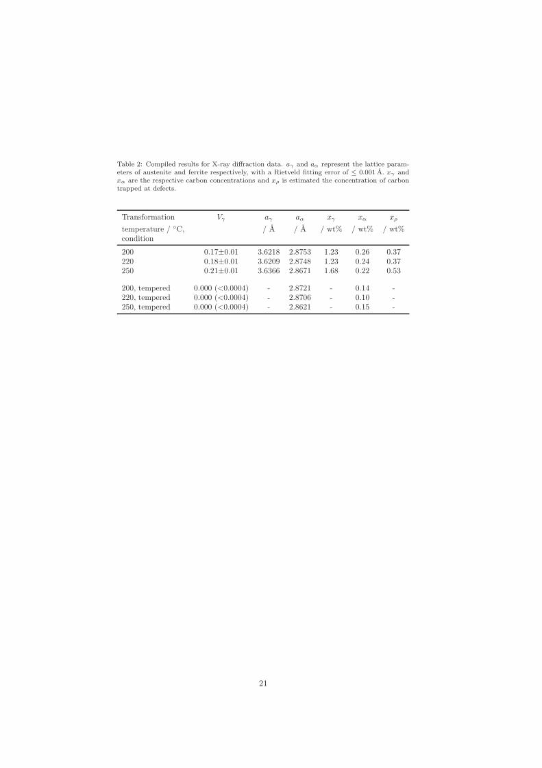
Table 2: Compiled results for X-ray diffraction data. aγ and aα represent the lattice param-eters of austenite and ferrite respectively, with a Rietveld fitting error of ≤ 0.001 A. xγ andxα are the respective carbon concentrations and xρ is estimated the concentration of carbontrapped at defects.
Transformation Vγ aγ aα xγ xα xρ
temperature / ◦C, / A / A / wt% / wt% / wt%condition
200 0.17±0.01 3.6218 2.8753 1.23 0.26 0.37220 0.18±0.01 3.6209 2.8748 1.23 0.24 0.37250 0.21±0.01 3.6366 2.8671 1.68 0.22 0.53
200, tempered 0.000 (<0.0004) - 2.8721 - 0.14 -220, tempered 0.000 (<0.0004) - 2.8706 - 0.10 -250, tempered 0.000 (<0.0004) - 2.8621 - 0.15 -
21

Table 3: Effect of tempering on the respective contributions of various factors to the strength-ening of the specimen isothermally held at 250◦C for 16 h. The dislocation densities of theuntempered and tempered samples have been taken to be 6.3×10¹⁵ m−2 [26] and 7×10¹³ m−2
respectively. A 50 nm thin foil has been assumed with respect to the stereological determina-tions for carbides.
Structural Component Strengthening contributions / MPa
As-transformed Tempered
Fe 168 168Solid solution of C and other solutes 986 178Thickness of the bainitic ferrite plates 1513 1337Dislocations 583 60Carbides 0 265
Sum of contributions σ =!
σi 3250 2008Power-weighted sum σk =
!
σik, k = 3.0 1666 1324
22