ee301 electronic circuits - dunia ilmiah · ee301 electronic circuits chapter 5 : filters ... the...
TRANSCRIPT
EE301
ELECTRONIC CIRCUITS
CHAPTER 5 : FILTERS
LECTURER : Engr. Muhammad Muizz
Electrical Engineering Department
Politeknik Kota Kinabalu, Sabah.
5.1 INTRODUCTION
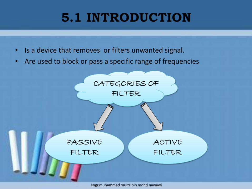
• Is a device that removes or filters unwanted signal.
• Are used to block or pass a specific range of frequencies
CATEGORIES OF FILTER
PASSIVE FILTER
ACTIVE FILTER
engr.muhammad muizz bin mohd nawawi

5.1 INTRODUCTION (cont…)
PASSIVE FILTERS ACTIVE FILTERS
Do not contain an amplifying device.
Contain some type of amplifyingdevice.
Use resistors, capacitors and / or inductors.
Use a transistor and / or operational amplifier in combination with resistors and capacitors to obtain the desired filtering effect.
Always has insertion loss Have very low insertion loss
DIFFERENCE BETWEEN PASSIVE FILTER & ACTIVE
FILTER
engr.muhammad muizz bin mohd nawawi
WHAT IS INSERTION LOSS?
• Passive filters never have a power output equal to or greater than the input because the filter always has insertion loss.
• This loss represents the difference between the power received at the load before insertion (installation) of a filter and the power after insertion.
• Is stated as the log of a ratio of power output to power input and is the result of power loss because of resistance in the circuit.
5.1 INTRODUCTION (cont…)
engr.muhammad muizz bin mohd nawawi
• Use only passive components such as inductors, capacitors and resistors.
• To minimize distortion in the filter characteristic, it is desirable to use inductors with high quality factors.
• However these are difficult to implement at frequencies below 1 kHz.
• Disadvantages:
– They are particularly non-ideal (lossy)
– They are bulky and expensive
5.2 PASSIVE FILTERS
engr.muhammad muizz bin mohd nawawi
5.2 PASSIVE FILTERS (cont…)
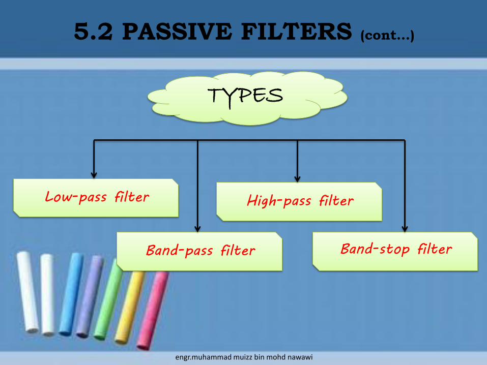
TYPES
Low-pass filter
Band-pass filter Band-stop filter
High-pass filter
engr.muhammad muizz bin mohd nawawi
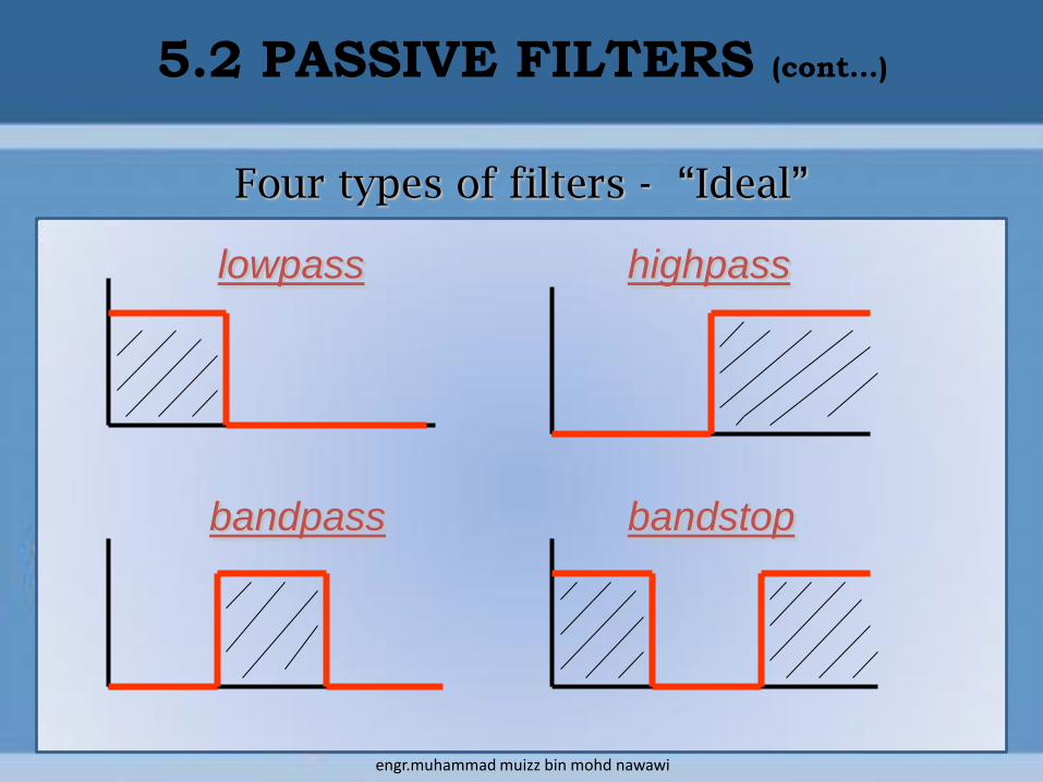
Four types of filters - “Ideal”
lowpass highpass
bandpass bandstop
5.2 PASSIVE FILTERS (cont…)
engr.muhammad muizz bin mohd nawawi
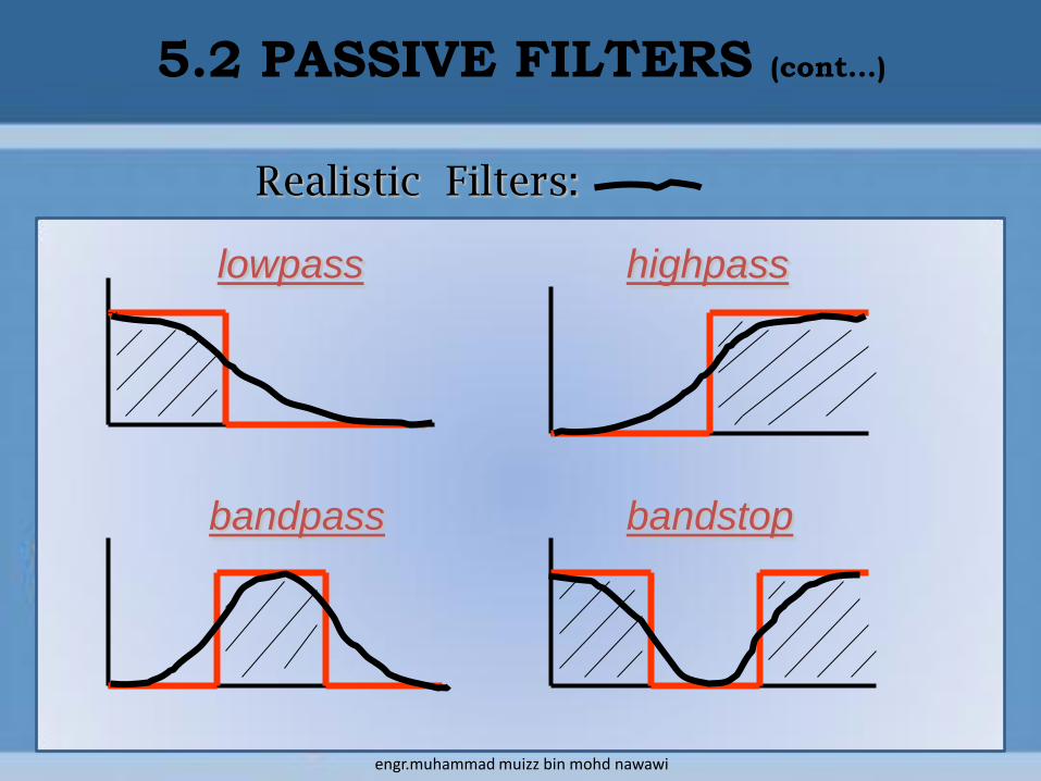
Realistic Filters:
lowpass highpass
bandpass bandstop
5.2 PASSIVE FILTERS (cont…)
engr.muhammad muizz bin mohd nawawi

5.2 PASSIVE FILTERS (cont…)
INTERACTIVE LEARNING
Ideal Filters
http://www.wisc-online.com/Objects/ViewObject.aspx?ID=ACE2603
ideal filter.swf
engr.muhammad muizz bin mohd nawawi

• Is a circuit that has a constant output voltage up to a cut-off or critical frequency, fc.
• The frequencies above fc are effectively shorted to ground and are described as being in the attenuation band, or stop-band.
• The frequencies below fc are said to be in the pass-band.
• Designed using combinations of resistors, inductors and capacitors.
5.2.1 LOW-PASS FILTER
engr.muhammad muizz bin mohd nawawi
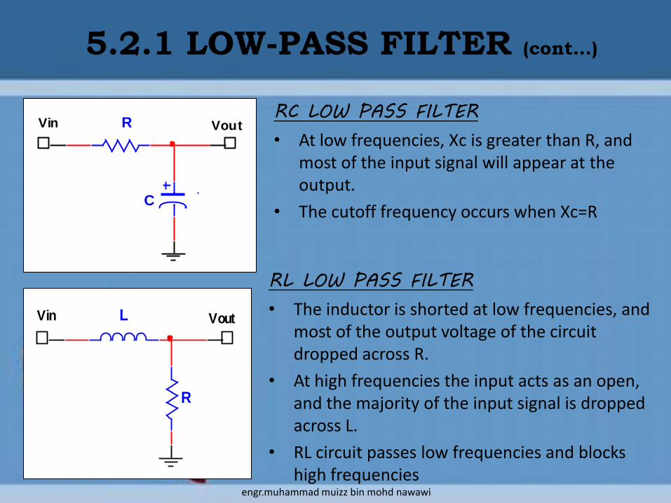
RC LOW PASS FILTER
• At low frequencies, Xc is greater than R, and most of the input signal will appear at the output.
• The cutoff frequency occurs when Xc=R
R
C
Vin Vout
5.2.1 LOW-PASS FILTER (cont…)
R
Vin VoutL
RL LOW PASS FILTER
• The inductor is shorted at low frequencies, and most of the output voltage of the circuit dropped across R.
• At high frequencies the input acts as an open, and the majority of the input signal is dropped across L.
• RL circuit passes low frequencies and blocks high frequencies
engr.muhammad muizz bin mohd nawawi

5.2.1 LOW-PASS FILTER (cont…)
RCfc
2
1
Response curve for low-pass filter
Cutoff frequency
L
Rfc
2
fc
0.707 -3 dB
• When output voltage is 0.707 of the input, the power output is 50% of the input power.
• This condition exists at fc (cutoff frequency)
• If Pout = ½ Pin, then a 3 dB loss of signal has occurred.
Passes low frequenciesAttenuates high frequencies
engr.muhammad muizz bin mohd nawawi
5.2.1 LOW-PASS FILTER (cont…)
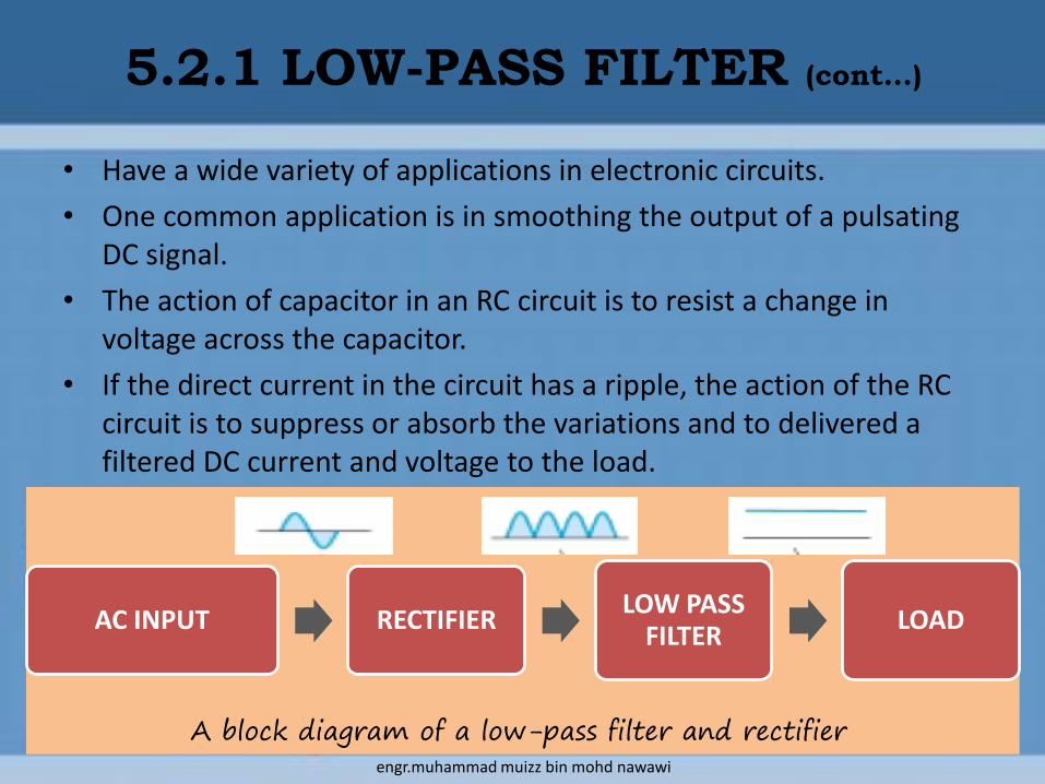
AC INPUT RECTIFIERLOW PASS
FILTERLOAD
• Have a wide variety of applications in electronic circuits.
• One common application is in smoothing the output of a pulsating DC signal.
• The action of capacitor in an RC circuit is to resist a change in voltage across the capacitor.
• If the direct current in the circuit has a ripple, the action of the RC circuit is to suppress or absorb the variations and to delivered a filtered DC current and voltage to the load.
A block diagram of a low-pass filter and rectifierengr.muhammad muizz bin mohd nawawi

Example 1
Determine the cutoff frequency of the
circuit.
Answer : 7.23 kHz
5.2.1 LOW-PASS FILTER (cont…)
Vin VoutL
10mHR
33kohm
Vin VoutR
2.2kohm
C 0.01µF
Example 2
For the circuit, calculate the half-power
frequency.
Answer : 52.52 kHz
engr.muhammad muizz bin mohd nawawi
• Allows frequencies above the cutoff frequency to appear at the output, but blocks or shorts to ground all those frequencies below the -3dB point on the curve.
5.2.2 HIGH-PASS FILTER
engr.muhammad muizz bin mohd nawawi
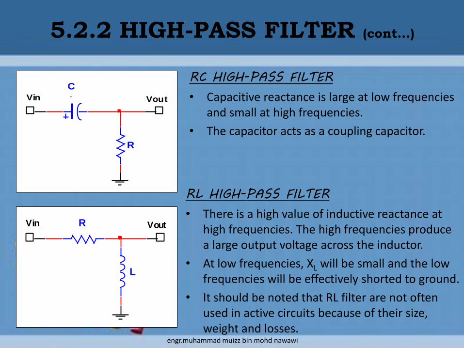
RC HIGH-PASS FILTER
• Capacitive reactance is large at low frequencies and small at high frequencies.
• The capacitor acts as a coupling capacitor.
5.2.2 HIGH-PASS FILTER (cont…)
RL HIGH-PASS FILTER
• There is a high value of inductive reactance at high frequencies. The high frequencies produce a large output voltage across the inductor.
• At low frequencies, XL will be small and the low frequencies will be effectively shorted to ground.
• It should be noted that RL filter are not often used in active circuits because of their size, weight and losses.
Vin VoutR
L
Vin Vout
R
C
engr.muhammad muizz bin mohd nawawi
5.2.2 HIGH-PASS FILTER (cont…)
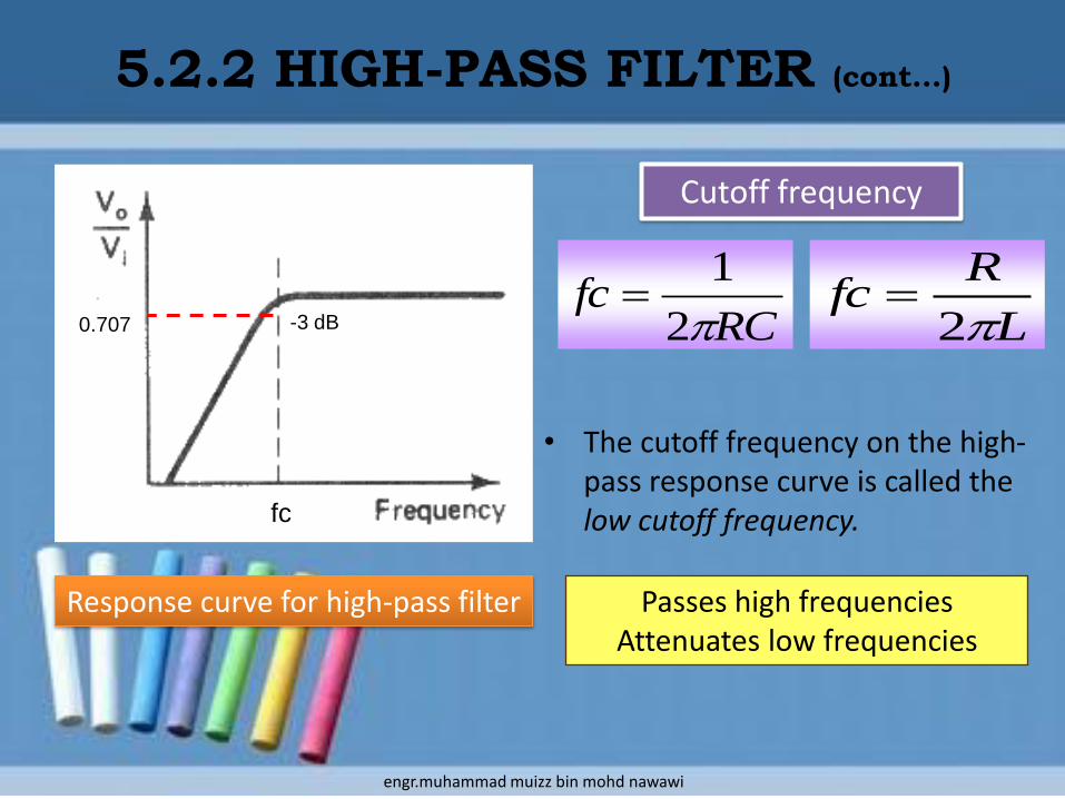
RCfc
2
1
Response curve for high-pass filter
Cutoff frequency
L
Rfc
2
• The cutoff frequency on the high-pass response curve is called the low cutoff frequency.fc
0.707 -3 dB
Passes high frequenciesAttenuates low frequencies
engr.muhammad muizz bin mohd nawawi

Example 3
Design an RL high-pass filter that will have a cutoff frequency of 1500 Hz.
Assume R = 1 kΩ
Answer : 106.1 mH
5.2.2 HIGH-PASS FILTER (cont…)
engr.muhammad muizz bin mohd nawawi
• Allows a certain range or band of frequencies to pass through it relatively unattenuated.
• Designed to have a very sharp, defined frequency response.
• Equivalent to combining a low-pass filter and a high-pass filter.
• The impedance of the circuit increases as the frequencies increase and decrease from the resonant frequency.
• Only the frequencies close to resonance are passed.
• All others are blocked because of high circuit impedance.
5.2.3 BAND-PASS FILTER
engr.muhammad muizz bin mohd nawawi

5.2.3 BAND-PASS FILTER (cont…)
C L
R
IO1
IO2
IO3
IO4
LCfr
2
1
Resonant frequency
CL R
Series resonant band-pass filter
Parallel resonant band-pass filter
engr.muhammad muizz bin mohd nawawi
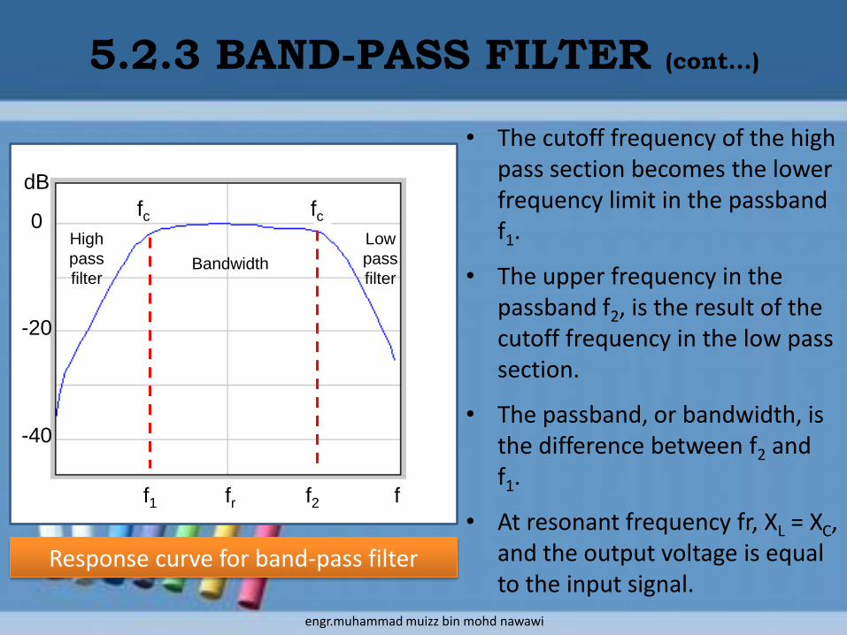
• The cutoff frequency of the high pass section becomes the lower frequency limit in the passband f1.
• The upper frequency in the passband f2, is the result of the cutoff frequency in the low pass section.
• The passband, or bandwidth, is the difference between f2 and f1.
• At resonant frequency fr, XL = XC, and the output voltage is equal to the input signal.
f1 fr f2 f
fcfcHigh
pass
filter
Low
pass
filterBandwidth
dB
0
-20
-40
5.2.3 BAND-PASS FILTER (cont…)
Response curve for band-pass filter
engr.muhammad muizz bin mohd nawawi
• Depending on the design and purpose of the band-pass filter, the bandwidth may be very wide or very narrow.
• Some of common uses of band-pass filters are:
i. Audio – to equalize sound levels
ii. Communications – to select a narrow band of radio frequencies.
iii. Audio – to produce speaker crossover networks.
5.2.3 BAND-PASS FILTER (cont…)
engr.muhammad muizz bin mohd nawawi
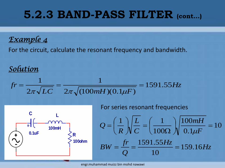
Example 4
For the circuit, calculate the resonant frequency and bandwidth.
Solution
5.2.3 BAND-PASS FILTER (cont…)
C
0.1uF
L
100mH
R
100ohm
HzFmHLC
fr 55.1591)1.0)(100(2
1
2
1
HzHz
Q
frBW
F
mH
C
L
RQ
16.15910
55.1591
101.0
100
100
11
For series resonant frequencies
engr.muhammad muizz bin mohd nawawi

Example 5
A parallel resonant band-pass filter has a lower cutoff frequency of 6.3 kHz
and an upper cutoff frequency of 8 kHz. Determine the bandwidth and
resonant frequency
Solution
5.2.3 BAND-PASS FILTER (cont…)
kHzkHzkHzfffr
kHzkHzkHzffBW
cc
cc
1.7)3.6)(8(
7.13.68
21
21
engr.muhammad muizz bin mohd nawawi

• Rejects signals at frequencies within a special band and passes signals at all other frequencies.
• Also referred to as a band-reject, notch, wave-trap, band-elimination, or band-suppression filter.
• Like the band-pass filter, the band-stop filter may also be formed by combining a low-pass and high-pass filter.
5.2.4 BAND-STOP FILTER
Low-
pass
filter
High-
pass
filter
Band
stop
fc fc• The band-stop filter is designed so
that the cutoff frequency of the low-pass filter is below that of the high-pass filter
engr.muhammad muizz bin mohd nawawi

SERIES RESONANT BAND-STOP FILTER
• When a series resonant LC circuit is connected in parallel with a load resistor, the LC network provides a low impedance shunt path.
• At resonance, the LC circuits acts as a short circuit and the signal does not pass through R.
• At frequencies above or below resonance, the LC circuit offer high resistance and current flow through the load.
5.2.4 BAND-STOP FILTER (cont…)
PARALLEL RESONANT BAND-STOP FILTER
• When the parallel LC network is at resonance, the impedance is very high and virtually no current flows to the load.
• The impedance decrease above and below resonance, so all other signals are passed through the filter.
C
L
R
C
L
R
engr.muhammad muizz bin mohd nawawi

• Popular in variety of applications, particularly audio electronics.
• These filters can be used in groups to provide equalization of the entire audio spectrum.
• For example, a typical one-third octave equalizer will contain 28 band-rejection filters.
• Each filter section is designed to remove a specific band of frequencies and provides up to 15 dB attenuation at its resonant frequency.
5.2.4 BAND-STOP FILTER (cont…)
engr.muhammad muizz bin mohd nawawi

Example 6
For the circuit, calculate the resonant frequency. Given L = 200 mH and
C = 0.01 µF.
Solution
5.2.4 BAND-STOP FILTER (cont…)
kHzFmHLC
fr 56.3)01.0)(200(2
1
2
1
C
L
R
engr.muhammad muizz bin mohd nawawi
5.3 ACTIVE FILTERS
• Use active components or devices such as transistors and op-amps, that can amplify.
• First order filter – use one resistor and one reactive component, which is either an inductor or capacitor.
• Second order filter – use two resistors and two reactive components.
engr.muhammad muizz bin mohd nawawi
5.3 ACTIVE FILTERS (cont…)
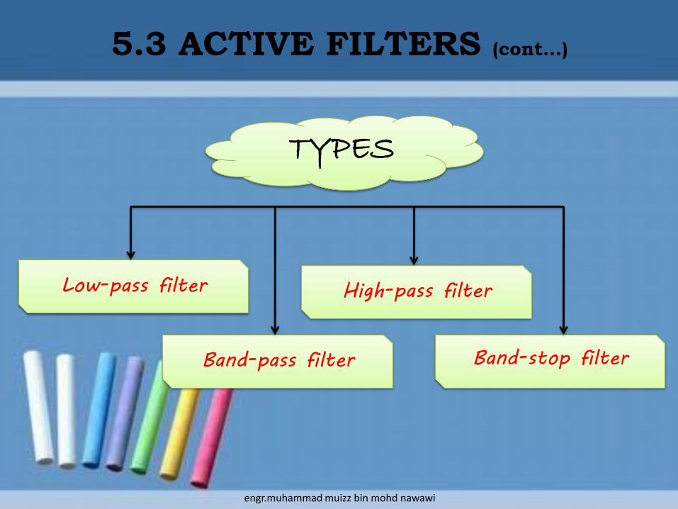
TYPES
Low-pass filter
Band-pass filter Band-stop filter
High-pass filter
engr.muhammad muizz bin mohd nawawi

• Advantages of active filters include:
– reduced size and weight, and therefore parasitic
– increased reliability and improved performance
– simpler design than for passive filters and can realize a wider range of functions as well as providing voltage gain
– in large quantities, the cost of an IC is less than its passive counterpart
5.3 ACTIVE FILTERS (cont…)
engr.muhammad muizz bin mohd nawawi

• Active filters also have some disadvantages:– limited bandwidth of active devices limits the highest attainable
pole frequency and therefore applications above 100 kHz (passive RLC filters can be used up to 500 MHz)
– the achievable quality factor is also limited
– require power supplies (unlike passive filters)
– increased sensitivity to variations in circuit parameters caused by environmental changes compared to passive filters
5.3 ACTIVE FILTERS (cont…)
• For many applications, particularly in voice and data communications, the economic and performance advantages of active filters far outweigh their disadvantages.
engr.muhammad muizz bin mohd nawawi

• At low frequencies, the capacitor has an extremely high capacitive reactance.
• Therefore, the circuit acts as an inverting amplifier with a voltage gain of –Rf/R1.
• At higher frequencies, the capacitive reactance of Cf decreases.
• This causes the voltage gain to decrease due to the increased amount of negative feedback.
• When Xcf = Rf, the voltage gain equals 70.7% of its midband value.
• This is the cutoff frequency fc:
5.3.1 ACTIVE LOW-PASS FILTER
Cf
Rf1
2
3R1
Vin
Vo
20 dB/decade
fc ff CRfc
2
1
engr.muhammad muizz bin mohd nawawi
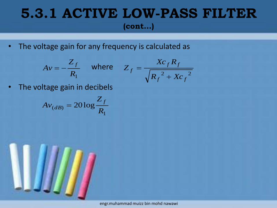
• The voltage gain for any frequency is calculated as
where
• The voltage gain in decibels
5.3.1 ACTIVE LOW-PASS FILTER (cont…)
1R
ZAv
f
22ff
ff
f
XcR
RXcZ
1)( log20
R
ZAv
f
dB
engr.muhammad muizz bin mohd nawawi
5.3.1 ACTIVE LOW-PASS FILTER (cont…)
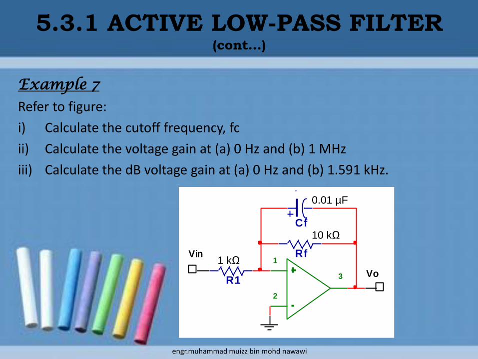
Example 7
Refer to figure:
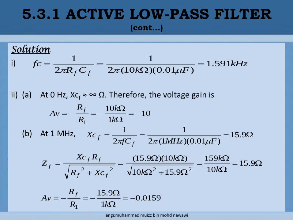
i) Calculate the cutoff frequency, fc
ii) Calculate the voltage gain at (a) 0 Hz and (b) 1 MHz
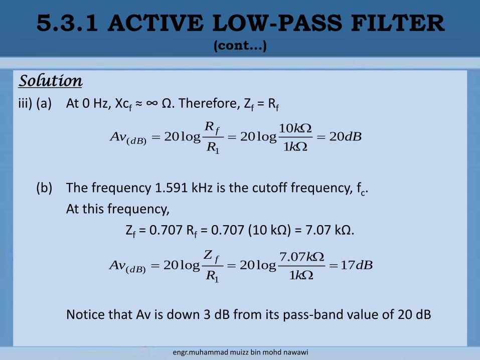
iii) Calculate the dB voltage gain at (a) 0 Hz and (b) 1.591 kHz.
Cf
Rf1
2
3R1
Vin
Vo
1 kΩ
0.01 µF
10 kΩ
engr.muhammad muizz bin mohd nawawi
Solution
i)
ii) (a) At 0 Hz, Xcf ≈ ∞ Ω. Therefore, the voltage gain is
(b) At 1 MHz,
101
10
1
k
k
R
RAv
f
9.1510
159
9.1510
)10)(9.15(
2222 k
k
k
k
XcR
RXcZ
ff
ff
f
5.3.1 ACTIVE LOW-PASS FILTER (cont…)
kHzFkCR
fcff
591.1)01.0)(10(2
1
2
1
9.15)01.0)(1(2
1
2
1
FMHzfCXc
ff
0159.01
9.15
1
kR
RAv
f
engr.muhammad muizz bin mohd nawawi
Solution
iii) (a) At 0 Hz, Xcf ≈ ∞ Ω. Therefore, Zf = Rf
(b) The frequency 1.591 kHz is the cutoff frequency, fc.
At this frequency,
Zf = 0.707 Rf = 0.707 (10 kΩ) = 7.07 kΩ.
Notice that Av is down 3 dB from its pass-band value of 20 dB
dBk
k
R
RAv
f
dB 201
10log20log20
1)(
5.3.1 ACTIVE LOW-PASS FILTER (cont…)
dBk
k
R
ZAv
f
dB 171
07.7log20log20
1)(
engr.muhammad muizz bin mohd nawawi
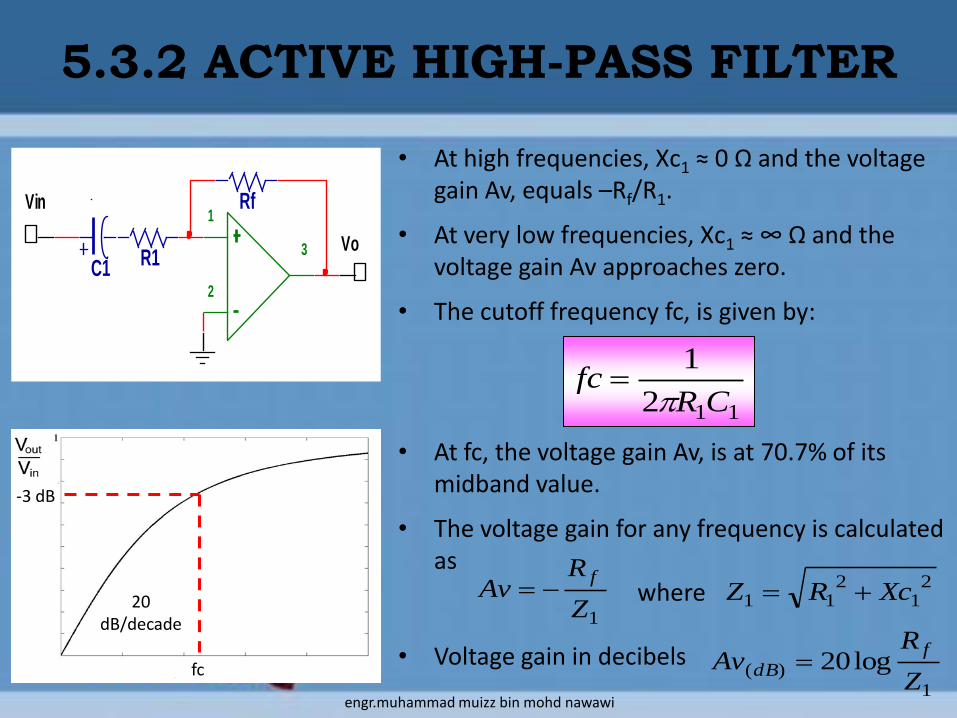
• At high frequencies, Xc1 ≈ 0 Ω and the voltage gain Av, equals –Rf/R1.
• At very low frequencies, Xc1 ≈ ∞ Ω and the voltage gain Av approaches zero.
• The cutoff frequency fc, is given by:
• At fc, the voltage gain Av, is at 70.7% of its midband value.
• The voltage gain for any frequency is calculated as
where
• Voltage gain in decibels
5.3.2 ACTIVE HIGH-PASS FILTER
112
1
CRfc
C1
Rf1
2
3R1
Vin
Vo
20 dB/decade
-3 dB
fc
1Z
RAv
f 2
12
11 XcRZ
1)( log20
Z
RAv
f
dB
engr.muhammad muizz bin mohd nawawi

5.3.2 ACTIVE HIGH-PASS FILTER(cont…)
Example 8
Refer to figure, calculate the cutoff frequency, fc.
Given C1 = 0.1 µF and R1 = 1 kΩ
Solution
C1
Rf1
2
3R1
Vin
Vo
kHzFkCR
fc 591.1)1.0)(1(2
1
2
1
11
engr.muhammad muizz bin mohd nawawi

• Besides low-pass and high-pass filters, other common types are band-pass filter (rejects high and low frequencies, passing only signal around some intermediate frequency).
• The simplest band-pass filter can be made by combining the first order low pass and high pass filters that we just looked at.
5.3.3 ACTIVE BAND-PASS FILTER
engr.muhammad muizz bin mohd nawawi

5.3.3 ACTIVE BAND-PASS FILTER(cont…)
• This circuit will attenuate low frequencies (ω<<1/R2C2) and high frequencies (ω >>1/R1C1), but will pass intermediate frequencies with a gain of -R1/R2.
• However, this circuit cannot be used to make a filter with a very narrow band. To do that requires a more complex filter.
engr.muhammad muizz bin mohd nawawi
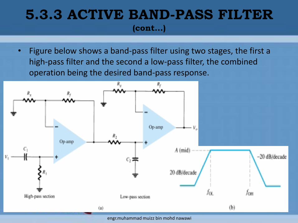
• Figure below shows a band-pass filter using two stages, the first a high-pass filter and the second a low-pass filter, the combined operation being the desired band-pass response.
5.3.3 ACTIVE BAND-PASS FILTER(cont…)
engr.muhammad muizz bin mohd nawawi
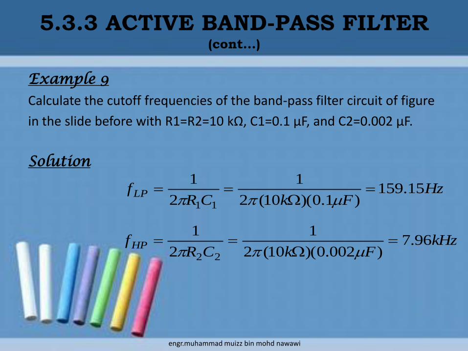
Example 9
Calculate the cutoff frequencies of the band-pass filter circuit of figure
in the slide before with R1=R2=10 kΩ, C1=0.1 µF, and C2=0.002 μF.
Solution
5.3.3 ACTIVE BAND-PASS FILTER(cont…)
HzFkCR
fLP 15.159)1.0)(10(2
1
2
1
11
kHzFkCR
fHP 96.7)002.0)(10(2
1
2
1
22
engr.muhammad muizz bin mohd nawawi

• In analyzing filters, the decibel (dB) unit is often used to describe the amount of attenuation offered by the filter.
• In basic terms, the decibel is a logarithmic expression that compares two power levels.
• The power gain or loss in decibels can also be computed from a voltage ratio if the measurement are made across equal resistance.
5.4 DECIBELS & FREQUENCY
RESPONSE CURVE
in
outdB
V
VN log20
Where Ndb = gain or loss in decibelsVin = input voltageVout = output voltage
engr.muhammad muizz bin mohd nawawi

Example 9
In figure below, calculate the attenuation, in decibels, at the following
frequencies: (a) 0 Hz, (b) 1.592 kHz, (c) 15.92 kHz.
Assume that Vin = 10 Vpp at all frequencies.
Solution:
a) At 0 Hz, Vout=Vin=10 Vpp,
since the capacitor C appears as an open.
Therefore,
5.4 DECIBELS & FREQUENCY
RESPONSE CURVE (cont…)
R
C
Vin Vout
dBV
V
P
PN
pp
pp
in
outdB 01log20
10
10log20log20
Solution:
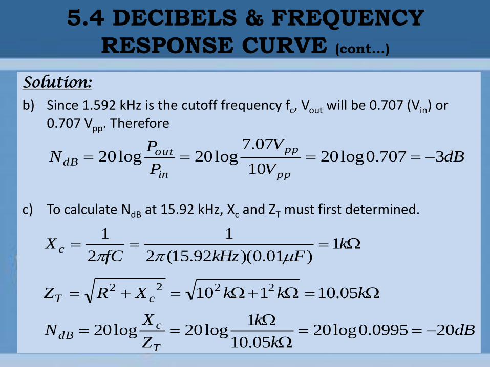
b) Since 1.592 kHz is the cutoff frequency fc, Vout will be 0.707 (Vin) or 0.707 Vpp. Therefore
c) To calculate NdB at 15.92 kHz, Xc and ZT must first determined.
5.4 DECIBELS & FREQUENCY
RESPONSE CURVE (cont…)
dBV
V
P
PN
pp
pp
in
outdB 3707.0log20
10
07.7log20log20
kFkHzfC
X c 1)01.0)(92.15(2
1
2
1
kkkXRZ cT 05.10110 2222
dBk
k
Z
XN
T
cdB 200995.0log20
05.10
1log20log20

5.4 DECIBELS & FREQUENCY
RESPONSE CURVE (cont…)
• In Example 9, notice that NdB is 0 dB at a frequency of 0 Hz, which is in the filter’s pass-band.
• This may seem unusual, but the 0 dB value simply indicates that there is no attenuation at this frequency.
• For an ideal passive filter, NdB = 0 dB in the pass-band.
• As another point of interest, NdB is -3 dB at the cutoff frequency of 1.592 kHz.
• Since Vout = 0.707 Vin at fc for any passive filter, NdB is always -3 dB at the cutoff frequency of a passive filter
• The NdB value of loss can be determined for any filter if the values of Vin and Vout are known

engr.muhammad muizz bin mohd nawawi