e&e syllabus 9-7-2015programs. it consists of six m.tech programs, which are affiliated to vtu....
TRANSCRIPT

SYLLABUS (With effect from 2013-2014) Out Come Based Education
¥ÀoÀåPÀæªÀÄ(±ÉÊPÀëtÂPÀªÀμÀð 2013-14)
¥sÀ°vÁA±À DzsÁjvÀ ²PÀët
V and VI Semester Bachelor Degree
inElectrical and Electronics Engineering
P.E.S. College of Engineering Mandya - 571 401, Karnataka
(An Autonomous Institution Affiliated�to VTU, Belagavi) Grant -in- Aid Institution
(Government of Karnataka) Accredited by NBA, New Delhi
Approved by AICTE, New Delhi.
¦.E.J¸ï. vÁAwæPÀ ªÀĺÁ«zÁå®AiÀÄ ªÀÄAqÀå-571 401, PÀ£ÁðlPÀ
(«.n.AiÀÄÄ, ɼÀUÁ« CrAiÀÄ°è£À ¸ÁéAiÀÄvÀÛ ÀA ÉÜ) Ph : 08232- 220043, Fax : 08232 – 222075,Web : www.pescemandya.org

Preface
PES College of Engineering, Mandya, started in the year 1962, has become autonomous in the academic year 2008-09. Since, then it has been doing the academic and examination activities successfully. The college is running eight undergraduate and eight Postgraduate programs. It consists of six M.Tech programs, which are affiliated to VTU. Other postgraduate programs are MBA and MCA.
India has recently become a Permanent Member by signing the Washington Accord. The accord was signed by the National Board of Accreditation (NBA) on behalf of India on 13th June 2014. It enables not only the mobility of our degree globally but also establishes equivalence to our degrees with that of the member nations such as Taiwan, Hong Kong, Ireland, Korea, Malaysia, New Zealand, Russia, Singapore, South Africa, Turkey, Australia, Canada and Japan. Among other signatories to the international agreement are the US and the UK. Implementation of Outcome Based Education (OBE), has been the core issue for enabling the equivalence and of Indian degrees and their mobility across the countries.
Our Higher Educational Institution has adopted the semester structure with OBE scheme and grading system.
The credit based OBE semester system provides flexibility in designing curriculum and assigning credits based on the course content and hours of teaching.
The OBE, emphasize setting clear standards for observable, measurable outcomes of programs in stages. There lies a shift in thinking, teaching and learning processes moving towards Students Centric from Teacher Centric education. OBE standards focus on mathematics, language, science, attitudes, social skills & moral values.
The key features which may be used to judge, if a system has implemented an outcome based education system is mainly Standard based assessments that determines whether students have achieved the stated standard. Assessments may take any form, so long as the process actually measure whether the student knows the required information or can perform the required task. Outcome based education is a commitment that all students of all groups will ultimately reach the same minimum standards. Outcome Based Education is a method or means which begins with the end in mind and constantly emphasizes continuous improvement.
In order to increase the Industry/Corporate readiness, many Soft Skills and Personality Development modules have been added to the existing curriculum of 2013-14.Industry Interactions have been made compulsory to enhance the field experience. In order to enhance creativity and innovation Mini Project is included in all undergraduate programs.
(Dr.H.V.RAVINDRA) Dean (Academic) Professor, Dept. of Mechanical Engg.
(B.DINESH PRABHU) Deputy Dean (Academic)
Associate Professor, Dept. of Automobile Engg

V & VI Semester Syllabus 2013-2014�
P.E.S.COLLEGE OF ENGINEERING, MANDYA-57140 (An Autonomous Institution under VTU, Belagavi)
Vision“An institution of high repute, imparting quality education to develop innovative and Humane engineers”
Mission“Committed to develop students potential through high quality teaching- learning processes and state of the art infrastructure”
DEPARTMENT OF ELECTRICAL & ELECTRONICS ENGINEERING
� Vision :Nurturing excellence in Electrical & Electronics Engineering by imparting professional education with values through innovative learning solutions to develop competent engineers.
� Mission:
� Enhance the competence of faculty and staff through FDP. � Provide students with strong theoretical foundation, research and innovation skills. � Develop interpersonal communication, team work and ethics. � Promote entrepreneurial qualities among students.
A. Program Educational Objectives (PEO)PEO1: Excel in professional career and/or higher education by acquiring knowledge in mathematical, computing and engineering principles
PEO 1.1.Progressing professional career PEO 1.2.Higher education
PEO2: Analyze real life problems, design computing systems appropriate to its solutions that are technically sound, economically feasible and socially acceptable
PEO 2.1.Analyzereal life problem PEO 2.2.Design and develop economically feasible and socially acceptable Computing Solutions
PEO3: Exhibit professionalism, ethical attitude, communications kills, team work in their profession and adapt to current trends by engaging in lifelong learning.
PEO 3.1.Professional conduct and interpersonal skills PEO 3.2.Adapting to current trends in technology

�
V & VI Semester Syllabus 2013-2014� �
B. Programme Outcomes (PO)
PO-1: Graduates will apply the knowledge of mathematics, Physics, chemistry and allied engineering subjects to solve problems in Electrical and Electronics Engineering.
PO-2: Graduates will Identify, formulate and solve Electrical and Electronics Engineering problems.
PO-3: Graduates will design Electrical and Electronics systems meeting the given specifications for different problems taking safety and precautions into consideration.
PO-4: Graduates will design, conduct experiments, analyze and interpret data
PO-5: Graduates will use modern software tools to model and analyze problems, keeping in view their limitations.
PO-6: Graduates will understand the impact of local and global issues / happenings on Electrical Engineers.
PO-7: Graduates will provide sustainable solutions for problems related to Electrical and Electronics Engineering and also will understand their impact on environment.
PO-8: Graduates will have knowledge of professional ethics and code of conduct as applied to Electrical engineers.
PO-9: Graduates will work effectively as an individual and as a member or leader in diverse teams and in multi-disciplinary settings.
PO-10: Graduates will communicate effectively in both verbal and written form.
PO-11: Graduates will have the ability for self- education and lifelong learning.
PO-12: Graduates will plan, execute and complete projects
�

P.E.S COLLEGE OF ENGINEERING, MANDYA (An Autonomous Institution under VTU)
SCHEME OF TEACHING AND EXAMINATION
V & VI Semester Syllabus 2013-2014� �
V Semester B.E Electrical & Electronics EngineeringSl. No. Course Code Course
TitleTeaching
Dept.
HoursPattern L:T:P:H
Credits Examination
Marks Exam
Durationin hours CIE SEE Total
1. P13EE51 Power Electronics E&E 4:0:0:4 4 50 50 100 3 2. P13EE52 Linear Automatic Control Systems E&E 3:2:0:5 4 50 50 100 3 3. P13EE53 Digital Signal Processing E&E 3:2:0:5 4 50 50 100 3 4. P13EE54 Power Transmission & Distribution E&E 4:0:0:4 4 50 50 100 3 5. P13EE55 Management & Entrepreneurship E&E 3:0:0:3 3 50 50 100 3 6. P13EE56 Operational Amplifiers & Linear
Integrated Circuits E&E 4:0:0:4 4 50 50 100 3
7. P13EEL57 Power Electronics Lab E&E 0:0:3:3 1.5 50 50 100 3 8. P13EEL58 Electrical Machines Lab-II E&E 0:0:3:3 1.5 50 50 100 3 9. P13HU59 Professional and Efficient
Avocation-I (PEA-I) HS&M 2:0:0:2 0 (50) --- --- ---
10. P13EEL510 Industry visit and interaction-II CS 0:0:1:1 -- (50) -- -- -- Total 26 400 400 800
VI Semester B.E Electrical & Electronics Engineering
Sl. No
Course Code Course Title Teaching
Dept.
HoursPattern
L:T:P:HCredits
ExaminationMarks
ExamDurationin hours CIE SEE Total
1. P13EE61 Power System Analysis and Stability. E&E 4:0:0:4 4 50 50 100 3 2. P13EE62 Switchgear & Protection E&E 4:0:0:4 4 50 50 100 3 3. P13EE63 Modern Control Theory E&E 3:2:0:5 4 50 50 100 3 4. P13EE64 Electrical Machine Design E&E 3:2:0:5 4 50 50 100 3 5. P13EE65 Microcontrollers & PLC E&E 3:0:0:3 3 50 50 100 3 6. P13EE66 Elective – A E&E 4:0:0:4 4 50 50 100 3 7. P13EEL67 Control Systems & DSP Lab E&E 0:0:3:3 1.5 50 50 100 3 8. P13EEL68 Microcontrollers & PLC Lab E&E 0:0:3:3 1.5 50 50 100 3
9. P13HU69 Professional and Efficient Avocation-I (PEA-II) * HS&M 2:0:0:2 0 (50) --- --- --
10. P13EEL610 Mini Project - II* E&E 0:0:1:1 -- (50) -- -- -- 11. P13EEL611 Power Plant & Industrial Visit* E&E ---- ---- --- ---- ----
Total 26 400 400 800 * PEA-I, , Industry visit and interaction-II, PEA-II, Mini Project & Power Plant & Industrial Visit: All students shall have topass this mandatory learning courses before completion of VIII-Semester
* MLC (Mandatory Learning Course) - Power plant & Industrial visit for 3 days during the Academic Semester. A brief report need to be submitted by the students.
Elective – A:Sl no. Course Code Course 1. P13EE661 Programmable Logic Controllers & SCADA 2. P13EE662 OOPS with C++ 3. P13EE663 Operations Research 4. P13EE664 Fuzzy Logic Systems
EVALUATION SCHEMEScheme Weightage Marks Event Break Up
CIE 50% 50 Test I Test II Quiz I Quiz II Assignment 35 35 5 5 10
SEE 50% 100 Questions to Set: 10 Questions to Answer: 5Scheme of SEE Question Paper (100 Marks)
Duration: 3Hrs Marks: 100 Weightage: 50% � Each of the two questions set shall be so comprehensive as to cover the entire contents of the unit. � There will be direct choice between the two questions within each Unit � Total questions to be set are 10. All carry equal marks of 20 � The number of subdivisions in each main question shall be limited to three only � Number of questions to be answered by students is 5

Department of Electrical & Electronics Engineering,
V & VI Semester Syllabus 2013-2014 Page 1
Course Title: Power Electronics Course Code: P13EE51 Semester: V L-T-P-H: 4-0-0-4 Credits - 4 Contact period : Lecture: 52 Hrs., Exam 3 Hrs. Weightage : CIE:50%; SEE:50%
Course Learning Objectives (CLOs) This course aims is to:
1. To get overview of various types of power semiconductor devices, their control and switching characteristics.
2. To understand the principle of operation, characteristics and performance parameters of controlled rectifiers and inverters.
3. To get overview of various types of commutations and understand the various types of 4. To study the operation and basic topologies of Ac-dc converters, Dc-Ac inverters, Dc-Dc
Choppers and Ac-Ac voltage controllers. 5. Developing the students with mathematical, scientific and computational skills to design,
analyze and solve problems related to various types of power converter systems
Course Content Unit – I
Power Semiconductor Devices: Introduction, Applications of Power Electronics, Power semiconductor devices, Control characteristics, Types of power electronics circuits, Peripheral effects. Power Transistors: Introduction, Power bipolar junction transistors Power MOSFETs, IGBTs and their Switching characteristics. 10 Hrs.
Unit – II Power Transistors: Base-drive control, Gate drive, di/dt and dv/dt limitations, Isolation of gate and base drives Thyristors: Introduction, Construction and Static V-I characteristics ; Two transistor model of thyristor, Turn-on and Turn-off, di/dt and dv/dt protection, Thyristor types, Series and parallel operation of thyristors, Thyristor firing circuits. 10 Hrs.
Unit – III Thyristor Commutation Techniques: Introduction, Commutation - natural, forced, self, impulse, resonant pulse & complementary AC Voltage Controllers: Introduction, Principle of ON-OFF control, Principle of phase control - single phase and bi-directional controller with resistive load and Inductive load. 10 Hrs.
Unit – IV DC Choppers: Introduction, Principle of step-down and step-up choppers, Step-down chopper with RL load and their analysis, Chopper classifications and their operations. Inverters: Introduction, Principle of operation, Performance parameters, Single phase half & full bridge inverters, Analysis of single phase inverters, voltage control of single phase inverters, 3phase voltage source inverters. 11 Hrs.
Unit –V Controlled Rectifiers: Introduction, Principle and operation of single phase controlled converter - half wave, Semi-converter, full wave, dual converter; 3 phase half wave & full wave converters.(excluding problems on three phase converters). 11 Hrs. TEXT BOOKS:-
1. Rashid, ”Power Electronics”, Prentice Hall India Pvt Ltd,2nd edition,2005. 2. P S Bhimbra, ”Power Electronics”, Khanna publishers,3rd edition,1999
REFERENCE BOOKS:- 1. G.K. Dubey, etal “Thyristorised Power Controllers”, Wiley Eastern edition,4th edition,1986 2. M.D. Singh &Kanchandoni,”Power Electronics”, TMH Publishers Company, reprint 2001.

Department of Electrical & Electronics Engineering,
V & VI Semester Syllabus 2013-2014 Page 2
Course Outcomes
After learning all the units of the course, the student is able to CO1. Select various types of power semiconductor devices to develop different types of
Power converter systems based on control characteristics. CO2. Analyze the different base drive control methodologies and various types of
Protection Circuits needed for converter system. CO3. Distinguish between various types of power converter systems, compare and analyze them. CO4. Understand and analyze the various types of commutation circuits and implement them. CO5. Design and develop different types of converter and inverter system.
Topic Learning Objectives
After learning all the topics of UNIT-I, the student is able to 1. Understand the basic concepts Power Electronics converter systems 2. Explain the operation of different types of power converter systems 3. Explain the control characteristics of semiconductor devices and peripheral effects 4. Explain the basic concepts of Bipolar transistor and their characteristics
After learning all the topics of UNIT-II, the student is able to
1. Explain the need of base drive control and their control techniques 2. Explain the constructions and working of a MOSFET, IGBT & Thyristor. 3. Explain the switching characteristics of a MOSFET, IGBT & Thyristor 4. Explain the various types of Gate drive and protection circuits 5. Explain the various types of Isolation circuits 6. Use of series & parallel operation of thyristor and their firing circuits
After learning all the topics of UNIT-III, the student is able to
1. Explain the need of commutation and different methods of commutation circuits 2. Analyze natural, forced and load commutation circuits 3. Understand the basic principle of Ac voltage controllers 4. Analyze the Ac voltage controller operation with various loads 5. Compare and select the different types commutation circuits 6. Compare and select the different types of Ac voltage controller circuits
After learning all the topics of UNIT-IV, the student is able to
1. Describe the basic principle of chopper configurations 2. Analyze and distinguish among various choppers configuration 3. Describe the basic principle of Inverter configurations 4. Analyze and distinguish among various inverter configurations 5. Compare and select the different types of chopper configuration 6. Compare and select the different types of inverter configuration
After learning all the topics of UNIT-V, the student is able to
1. Describe the basic principle of converter configurations 2. Analyze and distinguish the various converter configurations 3. Analyze and understand the idea of generating gating pattern for converter system Compare
and select the different types of converter system

Department of Electrical & Electronics Engineering,
V & VI Semester Syllabus 2013-2014 Page 3
Review Questions: 1. What do you mean by power Electronics? 2. With the help of block diagram explain the power converter system. 3. Mention the peripheral effects of Power converter system & what are their remedies? 4. With reference to control characteristics what is the difference between a Thyristor & GTO. 5. With reference to control characteristics what is the difference between a MOSFET & BJT. 6. With relevant circuit & waveform explain Ac-Dc conversion. 7. With relevant circuit & waveform explain Dc-Ac conversion. 8. Draw the circuit symbol their V-I characteristics of two semi conductor devices. 9. What are the advantages of Power Semiconductor devices?
10. Mention the Ideal characteristics of a semiconductor device. 11. Why the transistor is called as Bi polar device? 12. Explain the switching characteristics of a BJT. 13. What is the need of Base drive control? 14. Explain anti saturation control. 15. What is a need of Isolation circuits? 16. What is a need of protection circuits for semiconductor devices? 17. What is a Thyristor? Explain the construction details 18. Explain the static V-I characteristics of a Thyristor. 19. Why high dv/dt should able to trigger thyristor into conduction? 20. Why is pulse triggering is preferred for thyristors? 21. Name the various causes of over voltages in thyristors. 22. Why special heat sinks are necessary for thyristors? 23. Why does the thyristors required to be connected in series? 24. What is the difference between converter grade & inverter grade thyristors? 25. What do you mean by commutations? 26. What are the conditions to be satisfied to turn-off a thyristor 27. Which current among latching current and holding current is larger? 28. What is a need of two transistor analogy of a thyristor? 29. What is the need of understanding various voltage and current ratings? 30. What do you mean by natural commutation? 31. What do you mean by complementary commutation? 32. What is the difference between Auxiliary and main device? 33. What do you mean by an Ac voltage controller? 34. What is the difference between Ac voltage controller and Inverter? 35. Why short duration pulses are not sufficient for an Ac voltage controller for an RL load? 36. Distinguish between half & full wave Ac voltage control. 37. What are the two methods of control of an Ac voltage controller? 38. What is a Chopper? 39. Mention the applications of choppers. 40. What are the methods of duty cycle control in choppers? 41. Distinguish between step-up and step-down chopper. 42. What is the basis on which the choppers are classified? 43. What is an Inverter? What are their applications? 44. Distinguish between half & full bridge inverters. 45. Mention the methods of Voltage control in inverters. 46. What are the two possible modes of operation of 3-ph inverter? 47. What are the applications of controlled rectifiers? 48. Classify the different types of controlled rectifiers. 49. What is the effect of connecting a freewheeling diode in an half wave rectifier? 50. How in full bridge converter the role of converter and inverter can be interchanged

Department of Electrical & Electronics Engineering,
V & VI Semester Syllabus 2013-2014 Page 4
Lesson Plan Unit- I
1. Introduction to power electronics and their applications. 2. Description of Various types of semiconductor devices, their V-I chars, symbols and their
applications. 3. Explanation of various types of power converter systems 4. Power semiconductor devices and control chars 5. Power converter systems explanation, peripheral effects and their remedies 6. Introduction to power transistors, types of power transistors, construction and their
applications. 7. Principle of operation of BJTs with input and output chars 8. Switching characteristics of MOSFET. 9. Switching chars of IGBT and comparison between MOSFET and IGBT
10. Problems Unit-II
1. Description of various types of base drive control circuits, merits and demerits of each 2. Description of various limits and their protection circuits 3. Description of Isolation circuits 4. Introduction to thyristors and their families with the applications 5. Constructional features of thyristors and its principle of operations 6. Static chars of thyristors 7. Two transistor model of thyristors 8. Turn on and turn-off chars of thyristors 9. Series and parallel operations of thyristors
10. Thyristor firing circuits and problems Unit- III
1. Introduction to commutation and their requirement. Classification of commutation circuits 2. Types of commutation circuits-natural commutation and self-commutation 3. Types of commutation circuits-Impulse and resonant commutation 4. Types of commutation circuits- Complementary commutation and problems 5. Problems 6. Introduction to AC voltage controller, types and applications 7. Principle of on/off control and problems 8. Principle of phase control with resistive load 9. Principle of phase control with inductive load
10. Problems. Unit- IV
1. Introduction to choppers, classification and applications 2. Types of choppers A, B, C, D 3. Four quadrant chopper operation 4. Principle of Step-down and step-up chopper configurations 5. Problems. 6. Introduction to inverters, classification and their applications. Description of Performance
parameters of inverters 7. Various types of inverters with R and RL load 8. Three phase bridge inverters.120 degree mode 9. Three phase bridge inverters: 180 degree Mode
10. Numerical Problems 11. Numerical Problems

Department of Electrical & Electronics Engineering,
V & VI Semester Syllabus 2013-2014 Page 5
Unit- V 1. Introduction to rectifiers, classification and their applications 2. Principle of operation of half wave converter with R load. 3. Principle of operation of half wave converter with RL load and with freewheeling diode. 4. Half controlled converter operation 5. Full controlled converter operation. 6. Dual converter operation. 7. Problems. 8. Problems. 9. Three phase half wave converter operation
10. Three phase half wave converter operation
Course Articulation Matrix (CAM) Course Outcome – CO Program Outcome (ABET/NBA-(3a-k))
a b c d e f g h i j k 1 Select various types of power semiconductor devices to develop
different types of Power converter systems based on control characteristics.
L1 L M H _ L _ _ _ _ L
2 Analyze the different base drive control methodologies and various types of Protection Circuits needed for converter system.
L2 M L H _ L _ _ _ _ M
3 Distinguish between various types of power converter systems, compare and analyze them L3 M M H _ L _ _ _ _ M
4 Understand and analyze the various types of commutation circuits and implement them. L4 H M H _ H _ _ _ _ H
5 Design and develop different types of converter and inverter system. L3 H H M _ M _ _ _ _ _ M
L-Low, M-Moderate, H-High Course Assessment Matrix (CAM)
Course Outcome – CO Program Outcome (ABET/NBA-(3a-k)) a b c d e f g h i j k
1 To get overview of various types of power semiconductor devices, their control and switching characteristics
L1 1 2 3 _ 1 _ _ _ _ _ 1
2 To understand the principle of operation, characteristics and performance parameters of controlled rectifiers and inverters
L2 2 1 3 _ 1 _ _ _ _ _ 2
3 To study the operation and basic topologies of dc-dc switching regulators, inverters dc-ac and Ac-ac voltage controllers.
L3 2 2 3 _ 1 _ _ _ _ _ 2
4 Developing the students with mathematical, scientific and computational skills to analyze and solve problems related to various power converter systems.
L4 3 2 3 _ 3 _ _ _ _ _ 3
5 Design and develop different types of converter and inverter system. L3 3 3 2 _ 2 _ _ _ _ _ 2
1-Low, 2-Moderate, 3-High

Department of Electrical & Electronics Engineering,
V & VI Semester Syllabus 2013-2014 Page 6
Course Title: Linear Automatic Control Systems Course Code: P13EE52 Semester: V L-T-P-H: 3-2-0-5 Credits – 4 Contact period : Lecture: 52 Hrs., Exam 3 Hrs. Weightage : CIE:50%; SEE:50%
Course Learning Objectives (CLOs) This course aims to: 1. Derive the transfer function and mathematical model for a variety of electrical, mechanical
and electromechanical systems. 2. Find the time domain specifications and time response for a given system for various inputs. 3. Analyze the performance and stability of a given system through root locus, Polar plots,
Nyquist plots and Bode plots. Course Content
Unit – I Fundamental Concepts of Control Systems: Basic definitions of control systems, Classification, Open loop and Closed loop systems, types of feedback, effects of feedback on overall gain, stability, sensitivity and external disturbance or noise, Servomechanism. Modeling of Systems: Differential equations of physical systems, Determinations of transfer function models for Electrical, Mechanical, Electromechanical systems and Analogous systems. Block diagrams and Signal flow graphs: Transfer functions, Block diagram algebra, Signal Flow graphs (State variable formulation excluded). 10 Hrs.
Unit – II Transient and Steady State Response Analyses of Feedback Control Systems: Standard test signals, Unit step response of First and second order systems. Time response specifications: Transient response specifications of second order systems, steady state errors and static error constants. Effect of adding poles and zeros to open loop and closed loop transfer function, concepts of dominant poles of transfer function. 10 Hrs.
Unit – III Stability analysis: Concepts of stability, Asymptotic stability, impulse response stability, BIBO stability, necessary conditions for stability, Routh-Hurwitz stability criterion, Routh’s tabulation, special cases when Routh’s tabulation terminates prematurely. Root–Locus Techniques: The root locus concepts, summary of general rules for constructing Root Loci, Stability analysis, determination of transient performance specifications and the value of K for specified ξ , gain margin, Effects of adding poles and zeros to the product of G(S)H(S) on shape of the Root locus, Root contour. 10 Hrs.
Unit – IV Frequency-Response Analysis: Introduction, advantages and limitations of frequency domain methods, correlation between time response and frequency response, frequency response specifications- resonant peak, resonant frequency and bandwidth. Graphical Analysis of Frequency –Response: (i) Bode Plots: Gain margin, Phase Margin and stability, determination of K for different Gain margin and Phase Margin, determination of transfer function from Bode magnitude plot, Relative stability analysis. 10 Hrs.
Unit –V (ii) Polar plots: Gain margin and Phase Margin and stability, determination of K for different Gain margin and Phase Margin, effects of addition poles and zeros to G(S) on shape of the polar plots, Relative stability analysis. (iii) Nyquist plots: Pole-zero configurations, concept of encirclement, analytical function and singularities, mapping theorem, Nyquist stability criteria, and determination of stability from the Nyquist plot. 12 Hrs.

Department of Electrical & Electronics Engineering,
V & VI Semester Syllabus 2013-2014 Page 7
Text Books: 1. Benjamin .C Kuo and Farid Golnaraghi “Automatic Control Systems”,
8th edition, Wiley India, 2010. 2. I.J Nagrath& M. Gopal “Control System Engineering”, New Age International
Private Ltd, 5th edition 2012 Reference Books: 1. Katsuhiko Ogata, “Modern Control Engineering”, PHI Learning Private Limited,
5th edition, 2011 2. Norman S. Nise “Control System Engineering”, 5th edition, ISV,Wiley India, 2010.
Course Outcomes
After learning all the units of the course, the student is able to CO1. Do the linear modeling (Transfer Function) for Electrical, Mechanical
&Electromechanical systems with the analogy. CO2. Do the analysis of the second order system with the transient & steady
state performance specification & its importance CO3. Do the stability analysis of different systems with RH criterion &
Root locus technique CO4. Do the frequency response analysis using analytical & Bode diagram CO5. Do the relative stability analysis using Polar & Nyquist diagrams.
Topic Learning Objectives After learning all the topics of UNIT-I, the student is able to
1. Define (i) System (ii) Control System 2. Explain how control systems are classified? 3. Define and differentiate open loop and closed loop system by giving suitable examples 4. Explain the effects of feedback on overall gain, stability, sensitivity and external
disturbance and noise 5. Define the Transfer function of a system. 6. Explain the significance of a transfer function stating its advantages and features 7. Define and explain the following terms related to the transfer function of a system (i) Poles
(ii) Zeros (iii) Characteristic equation (iv) Pole -zero plot (v) Order 8. What is transfer function modeling of Control systems? 9. Derive the transfer function modeling of (i) Electrical (ii) Mechanical (iii) Electro
mechanical systems. 10. Explain the derivation of analogues networks using
(i) Force Voltage (ii) force Current analogy. 11. Derive the analogous electrical networks based on (i) Force Voltage (ii) force Current
analogy for different mechanical systems. 12. Derive the transfer function for field control and armature controlled DC motor. 13. What is block diagram representation? Explain with suitable example. 14. Block Diagram representation for different electrical and Mechanical systems. 15. State advantages and Disadvantages of the block diagram reduction technique. 16. Explain the block diagram reduction rules. 17. Deducing the Transfer Function of a Block Diagram using Black Diagram Reduction rules. 18. Define signal flow graph. 19. Define the different terms related to signal flow graph. 20. Explain the various properties of signal flow graph representation. 21. . Derive the signal flow graph for different systems? 22. Explain how to construct signal flow graph from (i) set of equations (ii) Block diagram with
suitable example.

Department of Electrical & Electronics Engineering,
V & VI Semester Syllabus 2013-2014 Page 8
23. Derive transfer function for different signal flow graphs using Mason’s gain formula.
After learning all the topics of UNIT-II, the student is able to 1. Define time response (transient response and steady state response) of a control system. 2. Explain the Impulse, step and ramp response of first order systems. 3. Explain how the damping ratio affects the time response of a second order system? 4. Define the following systems sketching their output waveform for a unit step input: (i)
under damped system (ii) undamped system (iii) Over damped system (iv) critically damped system
5. With a neat sketch explain all time domain specifications? 6. Derive the expressions for maximum overshoot, peak time, settling time and rise time in
terms of and ωn for a second order control system. 7. Determine the time domain specifications for second order systems 8. Explain how steady state error of control system is determined 9. Derive the expression for static error coefficients for different systems
10. Explain the effect of adding poles and zeros to open loop and closed loop transfer Function 11. Explain the importance of dominant poles of transfer function
After learning all the topics of UNIT-III, the student is able to
1. Define the following terms (i) stable system (ii) unstable system (iii) critically stable system (iv)Conditionally stable system
2. Explain the concepts of asymptotic stability, impulse response stability, BIBO stability. 3. Explain the R-H Criteria. 4. Determine the stability of a system for different characteristic equation and determine the
range of K for stability. 5. What is root-locus? Explain with suitable examples. 6. Explain the rules for sketching root-locus for different order systems 7. Explain how to determine the transient performance specifications and the value of K for
specified ξ, gain margin from the root locus 8. Explain the impact of adding poles and zeros to the product of G(s)H(s) on the shape of the
Root locus. 9. What is root contour?
After learning all the topics of UNIT-IV, the student is able to
1. What is frequency domain analysis? 2. Write a note on co-relation between time domain and frequency domain 3. Define and derive the expression for bandwidth of a second order system 4. Derive the expressions for Resonant peak Mr , resonant frequency r for the second order
system in terms of ξ and n. 5. Derive the frequency domain specifications for different systems. 6. What are Bode plots? State the advantages of Bode plots. 7. Explain the nature of Bode plots for (i) Poles at origin (ii) simple pole (iii) simple zero 8. Explain the concept of gain margin and phase margin. Explain how these values help in
studying relative stability 9. Determine the value of K for different Gain margin and Phase Margin.
10. Derive the transfer function from the Bode magnitude plot. 11. Explain how the type of a system determines the nature of polar plots.

Department of Electrical & Electronics Engineering,
V & VI Semester Syllabus 2013-2014 Page 9
After learning all the topics of UNIT-V, the student is able to 1. Explain how phase and gain margin are calculated from Polar plot. 2. Explain how to determine the value of K for different Gain margin and Phase Margin. 3. Explain the effects of addition poles and zeros to G(S) on shape of the polar plots. 4. Explain the concepts of Pole-zero configurations from the Nyquist point of view, concept
of encirclement, analytical function and singularities, mapping theorem. 5. Explain Nyquist stability criterion. 6. Draw Nyquist plots and discuss the stability of closed loop system from the given open-
loop transfer function. 7. What are the advantages of Nyquist method?
Review Questions 1. Define (i) System (ii) Control System 2. Explain how control systems are classified? 3. Define and differentiate open loop and closed loop system by giving suitable examples 4. Explain the effects of feedback on overall gain, stability, sensitivity and external disturbance
and noise 5. Define the Transfer function of a system. 6. Explain the significance of a transfer function stating its advantages and features 7. Define and explain the following terms related to the transfer function of a system (i) Poles
(ii) Zeros (iii) Characteristic equation (iv) Pole -zero plot (v) Order 8. What is transfer function modeling of Control systems? 9. Derive the transfer function modeling of (i) Electrical (ii) Mechanical
(iii) Electromechanical systems. 10. Explain the derivation of analogues networks using (i) Force Voltage
(ii) force Current analogy. 11. Derive the analogous electrical networks based on (i) Force Voltage (ii) force Current
analogy for different mechanical systems. 12. Derive the transfer function for field control and armature controlled DC motor. 13. Define time response (transient response and steady state response) of a control system. 14. Explain the Impulse, step and ramp response of first order systems. 15. Explain how the damping ratio affects the time response of a second order system? 16. Define the following systems sketching their output waveform for a unit step input: (i) under
damped system (ii) undamped system (iii) Over damped system (iv) critically damped system
17. With a neat sketch explain all time domain specifications? 18. Derive the expressions for maximum overshoot, peak time, settling time and rise time in
terms of and ωn for a second order control system. 19. Determine the time domain specifications for second order systems 20. Explain how steady state error of control system is determined 21. Derive the expression for static error coefficients for different systems 22. Explain the effect of adding poles and zeros to open loop and closed loop transfer Function 23. Explain the importance of dominant poles of transfer function 24. Define the following terms (i) stable system (ii) unstable system (iii) critically stable system
(iv)Conditionally stable system 25. Explain the concepts of asymptotic stability, impulse response stability, BIBO stability. 26. Explain the R-H Criteria. 27. Determine the stability of a system for different characteristic equation and determine the
range of K for stability. 28. What is root-locus? Explain with suitable examples. 29. Explain the rules for sketching root-locus for different order systems

Department of Electrical & Electronics Engineering,
V & VI Semester Syllabus 2013-2014 Page 10
30. Explain how to determine the transient performance specifications and the value of K for specified ξ, gain margin from the root locus
31. Explain the impact of adding poles and zeros to the product of G(s)H(s) on the shape of the Root locus.
32. What is root contour? 33. What is frequency domain analysis? 34. Write a note on co-relation between time domain and frequency domain 35. Define and derive the expression for bandwidth of a second order system 36. Derive the expressions for Resonant peak Mr ,resonant frequency r for the second order
system in terms of ξ and n. 37. Derive the frequency domain specifications for different systems. 38. What are Bode plots? State the advantages of Bode plots. 39. Explain the nature of Bode plots for (i) Poles at origin (ii) simple pole (iii) simple zero 40. Explain the concept of gain margin and phase margin. Explain how these values help in
studying relative stability 41. Determine the value of K for different Gain margin and Phase Margin. 42. Derive the transfer function from the Bode magnitude plot. 43. Explain how the type of a system determines the nature of polar plots. 44. Explain how phase and gain margin are calculated from Polar plot. 45. Explain how to determine the value of K for different Gain margin and Phase Margin. 46. Explain the effects of addition poles and zeros to G(S) on shape of the polar plots. 47. Explain the concepts of Pole-zero configurations from the Nyquist point of view, concept of
encirclement, analytical function and singularities, mapping theorem. 48. Explain Nyquist stability criterion. 49. Draw Nyquist plots and discuss the stability of closed loop system from the given open-
loop transfer function. 50. What are the advantages of Nyquist method?
Lesson Plan
Unit- I 1. Introduction to Control Systems and their Classification.
Difference between Open Loop and Closed Loop system with suitable examples 2. Effects of feedback on overall gain, stability, sensitivity and external disturbance and noise 3. Introduction to Block Diagram Representation with suitable examples 4. Block diagram representation for different Electrical, Mechanical and Electro Mechanical
Systems 5. Explain the Block Diagram Reduction rules 6. Obtaining the Transfer Function Model of a given Block Diagram using Block Diagram
Reduction rules. 7. Introduction to Signal Flow Graph and various terms and properties associated with it 8. Explain how to construct signal flow graphs from (i) set of equations
(ii) Block diagram with suitable example 9. Problems based on derivation of Signal Flow Graphs for various system
10. How to derive the transfer function from signal flow graphs using Mason’s gain formula Unit-II
1. Introduction to Transfer Functions and its significance and advantages 2. Explain Transfer function Modeling of Control systems and discuss the following terms
related to the transfer function of a system (i) Poles (ii) Zeros (iii) Characteristic equation (iv) Pole -zero plot (v) Order
3. Transfer Function Modeling of (i) Electrical (ii) Mechanical (iii) Electromechanical systems

Department of Electrical & Electronics Engineering,
V & VI Semester Syllabus 2013-2014 Page 11
4. Explain the derivation of analogues networks using (i) Force Voltage (ii) Force Current analogy.
5. Derive the analogous electrical networks for different mechanical systems based on (i) Force Voltage (ii) Force Current analogy
6. Derive the transfer function for field control and armature controlled DC motor 7. Explain the concepts of Zero state response, Zero Input response of a system 8. Determine the transfer function of a system with multiple inputs and multiple outputs 9. Introduction to time response (transient response and steady state response) of a control
system 10. Explain the Impulse, step and ramp response of first order systems
Unit-III
1. Define the following systems sketching their output waveform for a unit step input: (i) under damped system (ii) undamped system (iii) Over damped system (iv) critically damped system
2. Definition and derivation of various Time Domain Specifications 3. Time Domain Specifications of a Second Order System. Derivation of expressions for
maximum overshoot, peak time, settling time and rise time in terms of and ωn. 4. Explain how steady state error of control system is determined. 5. Derive the expression for static error coefficients for different systems. 6. Explain the effect of adding poles and zeros to open loop and closed loop transfer function 7. Explain the importance of dominant poles of transfer function. 8. Explain how the damping ratio affects the time response of a second order system 9. Define the following terms (i) stable system (ii) unstable system (iii) critically stable system
(iv) conditionally stable system 10. Explain the concepts of asymptotic stability, impulse response stability, BIBO stability
Unit-IV
1. Explain the R-H Criteria 2. Problems to determine the stability of a system for different characteristic equation and
determine the range of K for stability 3. Introduction to Root Locus 4. Rules for sketching root-locus for different order systems 5. Sketch the root-locus for different systems and stability range of K and different
performance specifications 6. Explain how to determine the transient performance specifications and the value of K for
specified ξ, gain margin from the root locus 7. Explain the impact of adding poles and zeros to the product of G(s)H(s) on the shape of the
Root locus 8. Determine the stability of a system for different characteristic equation and determine the
range of K for stability 9. Introduction to Frequency Domain Analysis. Co-relation between time domain and
frequency domain 10. Define and derive the expression for bandwidth of a second order system. Derive the
expressions for Resonant peak Mr , resonant frequency for the second order system in terms of ξ and
Unit-V 1. What are Bode-Plots? State the advantages of Bode plots 2. Explain the nature of bode plots for (i) Poles at origin (ii) simple pole (iii) simple zero 3. Explain the concept of gain margin and phase margin to determine the stability. Explain how
these values help in studying relative stability

Department of Electrical & Electronics Engineering,
V & VI Semester Syllabus 2013-2014 Page 12
4. Draw the bode diagram for different open-loop transfer functions and mark the following on the bode diagram, recording the numerical values (i) gain crossover frequency (ii) phase margin (iii) Phase crossover frequency (ii) gain margin and discuss the stability
5. Derivation of Transfer Function from Bode magnitude Plot with problems 6. Introduction to Polar Plots. Explain polar plots for Type 0, 1, 2 systems. Explain how type of
a system determines the nature of polar plot 7. Explain how to obtain gain margin and phase margin from polar plots and discuss the
stability 8. Explain how to determine the value of K for different Gain margin & phase margin 9. Explain the effects of addition poles and zeros to G(S) on shape of the polar plots
10. Explain the concepts Pole-zero configurations, concept of encirclement, analytical function and singularities, mapping theorem
11. Explain Nyquist stability criterion and explain the advantages of Nyquist method? 12. Draw Nyquist plots and discuss the stability of closed loop system from the given open-loop
transfer system.
Course Articulation Matrix (CAM)�
Course Outcome – CO�� Program Outcome
(ABET/NBA-(3a-k))�a b c d e f g h i j k
1 Do the linear modeling (Transfer Function) for Electrical, Mechanical & Electromechanical systems with the analogy.
L2 H H M _ M _ L _ M _ H
2 Do the analysis of the second order system with the transient & steady state performance specification & its importance
L1 H L M _ H _ M _ M M H
3 Do the stability analysis of different systems with RH criterion & Root locus technique
L3 H H H _ H _ M _ M M H
4 Do the frequency response analysis using analytical & Bode diagram
L4 H H M _ H _ M _ M M H
5 Do the relative stability analysis using Polar & Nyquist diagrams
L4 H L M _ L _ H _ M _ H
� L-Low, M-Moderate, H-High�Course Assessment Matrix (CAM)�
Course Outcome – CO � Program Outcome
(ABET/NBA-(3a-k))�� a b c d e f g h i j k
1 Do the linear modeling (Transfer Function) for Electrical, Mechanical & Electromechanical systems with the analogy.
L2 3 3 2 _ 2 _ 1 2 _ 3
2 Do the analysis of the second order system with the transient & steady state performance specification & its importance
L1 3 1 2 _ 3 _ 2 2 2 3
3 Do the stability analysis of different systems with RH criterion & Root locus technique
L3 3 3 3 _ 3 _ 2 2 2 3
4 Do the frequency response analysis using analytical & Bode diagram
L4 3 3 2 _ 3 _ 2 2 2 3
5 Do the relative stability analysis using Polar & Nyquist diagrams
L4 3 1 2 _ 1 _ 3 2 _ 3
� �-Low, 2-Moderate, 3-High

Department of Electrical & Electronics Engineering,
V & VI Semester Syllabus 2013-2014 Page 13
Course Title: Digital Signal Processing Course Code: P13EE53 Semester: V L-T-P-H: 3-2-0-5 Credits - 4 Contact period : Lecture: 52 Hrs., Exam 3 Hrs. Weightage : CIE:50%; SEE:50%
Course Learning Objectives (CLOs) This course aims to: 1. Describe the concept of discrete-time Fourier transform (DFT) and its Inverse DFT(IDFT). 2. Analyze the discrete signals by using the different properties of DFT 3. Understand and use the FFT algorithms and its applications 4. Understand the general design and implementation of digital structures 5. Carry out the design and implementation of IIR filters and FIR filters
Course Content Unit – I
Introduction to discrete Fourier transform (DFT) : Introduction, Frequency domain sampling and reconstruction of discrete time signals, definitions of Discrete Fourier Transform (DFT) and Inverse Discrete Fourier transform (IDFT). DFT as a linear transformation, DFT Relationship to z-transforms, DFT of standard signals, using the DFT to find the IDFT. 10 Hrs.
Unit – II Properties of DFT: Properties of DFT – Periodicity, Linearity, Circular Symmetries of a sequence. Symmetry properties of the DFT - real valued sequences, real & even sequences, real & odd sequences, purely imaginary sequences. Multiplication of two DFTs and circular convolution. Additional DFT properties – time reversal of sequences, circular time shift of a sequence, circular frequency shift, complex conjugate properties, multiplication of two sequences, Parsaval’s theorem. 11 Hrs.
Unit – III Fast Fourier Transform (FFT) : Efficient computation of the DFT: FFT algorithms - Direct computation of DFT, Radix-2 algorithms - Decimation In Time and Frequency algorithms, Applications of FFT algorithms -Efficient computation of the DFTs of two real sequences (using a Single N-point DFT), Efficient computation of the DFTs of 2N point real sequences. 10 Hrs.
Unit – IV Implementation of Discrete Time Systems: Structures for realization of discrete time systems. (a)Structures of FIR systems: direct form structure, cascade form structure, Lattice structure. (b)Structures for IIR systems: direct form structure, signal flow graphs & transposed structures, cascade form structures, parallel form structures, lattice structure for IIR systems. 10 Hrs.
Unit –V Design of filters: a) Design of Analog IIR filters – Analog Filter Specifications, classification of analog Filters, Butterworth analog filter, frequency/spectral transformations, design of Low pass (analog) Butterworth filters. b) Digital filters: Design of IIR filters from analog filters -Bilinear transformation, Impulsive invariance transformation. c) Design of FIR filters: Introduction, design of Linear phase FIR filter using windows. Windowing functions - rectangular window, Bartlett window, Hanning window, Hamming window, Blackman window. 11 Hrs. Text books:
1. Proakis, “Digital Signal Processing - Principle, Algorithms & Applications”, 3rd edition, Pearson Education / PHI, 2013.

Department of Electrical & Electronics Engineering,
V & VI Semester Syllabus 2013-2014 Page 14
2. Dr. D. Ganesh Rao&Vineeta P. Gejji , “Digital Signal Processing”, Sanguine Technical Publishers, 2013.
Reference books: 1. J.S. Chitode , “Digital Signal Processing” - Technical publications. Pune. 2013
Course Outcomes
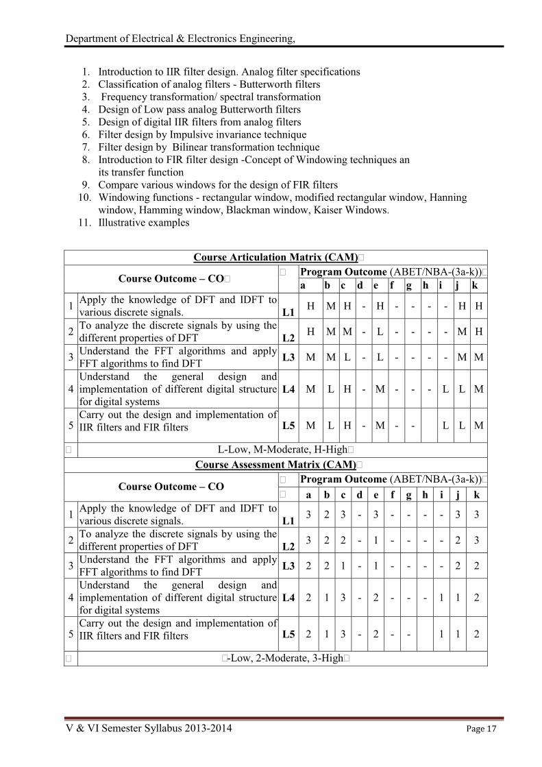
After learning all the units of the course, the student is able to CO1. Apply the knowledge of DFT and IDFT to various discrete signals. CO2. To analyze the discrete signals by using the different properties of DFT CO3. Understand the FFT algorithms and apply FFT algorithms to find DFT CO4. Understand the general design and implementation of different digital structure for
digital systems CO5. Carry out the design and implementation of IIR filters and FIR filters
Topic Learning Objectives After learning all the topics of UNIT-I, the student is able to
1. Explain the frequency domain sampling and reconstruction of discrete time signals 2. Explain concept of Discrete Fourier Transform (DFT) and Inverse Discrete Fourier
transform (IDFT) for the frequency domain transformations 3. Perform or determine DFT/IDFT on various signals 4. Solve problems by matrix relations for computing DFT and IDFT
After learning all the topics of UNIT-II, the student is able to 1. Apply the knowledge of various properties of DFT 2. Apply Various Symmetry Properties 3. Determine DFT of real even and real odd sequences 4. Determine DFT of complex conjugate sequence 5. Explanation of Parsaval’s theorem 6. Understanding N-point DFTs of two real sequences using a Single N-point DFT
After learning all the topics of UNIT-III, the student is able to
1. Explain the concept of Fast Fourier Transform (FFT) 2. Analyze -Decimation In Time(DIT) algorithm 3. Analyze - Decimation In Frequency (DIF) algorithm 4. Applications of FFT algorithms
After learning all the topics of UNIT-IV, the student is able to
1. Understanding digital structures 2. Analyze various Structures of FIR systems 3. Explain the structure of IIR systems 4. Analyze Structures for IIR systems 5. Solve problems based on FIR and IIR systems
After learning all the topics of UNIT-V, the student is able to 1. Analysis of analog filter specifications 2. Design of Low pass analog Butterworth filters 3. Design digital IIR filters from analog filters 4. Apply the frequency transformations 5. Design of digital filter by Impulsive invariance technique and bilinear transformation
technique 6. Understanding FIR filter design 7. Compare various windowing techniques

Department of Electrical & Electronics Engineering,
V & VI Semester Syllabus 2013-2014 Page 15
Review Questions: 1. What is the need of frequency domain sampling? 2. What is aliasing effect? Explain frequency domain sampling. 3. Give the definitions of DFT and IDFT. 4. Compute DFT of unit sample. 5. Find the N-point DFT of the given sequence x(t). 6. Show that the DFT and IDFT form a consistent discrete Fourier transform pairs. 7. Establish the relationship between z-transform and DFT 8. State properties of DFT 9. State and prove the following properties of the DFT.
(i) Circular time reversal (ii) Circular time shift (iii) Circular frequency shift 10. Explain circular convolution 11. What is difference between circular convolution and Linear convolution. 12. Prove that the DFT of a real and even sequence is purely real and even. 13. Prove the time shifting property of DFT 14. In the direct computation of N-point DFT of a sequence, how many multiplications,
additions and trigonometric function evaluation are required? 15. What is FFT? 16. Give the classification of various FFT algorithms 17. Explain radix -2 DIT-FFT algorithm. Explain how calculations are reduced. 18. Develop an 8-point DIT-FFT 19. Compare DIF-FFT algorithm with DIT-FFT algorithm 20. Use 8-point DIF-FFT radix- 2 algorithm to find the DFT of the given sequence x(n) 21. Write the short notes on the following: (i) Butterfly computation.(ii) In place computation
(iii) bit reversal 22. Calculate the IDFT of the given X(k) , using inverse radix-2 DIT-FFT algorithm 23. Explain the implementation of FIR filters using direct form and cascaded form realizations. 24. Explain linear phase FIR structures. What are the advantages of such structures? 25. Realize a linear phase FIR filter with given impulse response h(n). 26. Realize the FIR filter (i) direct form (ii) Cascaded form for the given transfer function H(z). 27. Explain the Direct form-I and Direct form-II structure of IIR system 28. Obtain the cascade and parallel form for the given H(z). 29. What is transposed structure, explain with suitable example. 30. Compare the main features of analog and digital filters. 31. Explain the frequency transformations in analog domain 32. Explain the frequency transformations in digital domain 33. Explain in detail Butterworth filter approximation. 34. Explain the design of analog Butterworth low pass IIR filter. 35. Explain “impulse invariant technique” of designing digital –IIR filter with a relevant
example. 36. Explain the bilinear transform method of IIR filter designing. 37. What is warping effect? Explain the poles and zeros mapping procedure clearly. 38. Compare impulse invariance and bilinear transformation methods. 39. Mention the properties of FIR digital filters. State their importance. 40. Derive the necessary conditions for FIR filters to have linear phase characteristics. 41. Compare various windows for the design of FIR filters. 42. Explain various types of windows used in the design of FIR filters. Write their analytical
equations and draw the frequency response characteristics of each window.

Department of Electrical & Electronics Engineering,
V & VI Semester Syllabus 2013-2014 Page 16
Lesson Plan Unit-I
1. Introduction to Digital Signal Processing 2. Definition of Discrete Fourier Transform (DFT) and Inverse Discrete Fourier transform
(IDFT) 3. Different methods of calculating DFT 4. DFT of standard signals 5. DFT as a linear transformation – Matrix relations for computing DFT and IDFT 6. Problems based on DFT of different signals 7. Problems based on matrix method of DFT 8. Obtaining IDFT from DFT 9. Numerical Problems to determine IDFT
10. Solve the problems to find DFT/IDFT
Unit-II 1. Explanation of properties of DFT: Linearity, circular time shift and circular frequency shift 2. Symmetry Properties 3. DFT of real even and real odd sequences 4. DFT of complex conjugate sequence 5. Circular Convolution 6. Problems based on Circular Convolution 7. Time reversal of sequences, multiplication of two sequences 8. Parsaval’s theorem. 9. N-point DFTs of two real sequences using a Single N-point DFT
10. Numerical Problems 11. Numerical Problems
Unit-III 1. Introduction to Fast Fourier Transform (FFT) 2. Explanation of Decimation In Time(DIT) algorithm 3. Explanation of Decimation In Frequency(DIF) algorithm 4. Problems using Decimation In Time(DIT) algorithm 5. Problems using Decimation In Time(DIT) algorithm 6. Problems using Decimation In Frequency (DIF) algorithm 7. Applications of FFT algorithms 8. Efficient computation of two real sequences & 2N real sequences 9. Problems based on FFT algorithms
10. Problems based on FFT algorithms
Unit-IV 1. Introduction to digital structures. 2. Structures of FIR systems: direct from structure, cascade structure, lattice structure. 3. Problems on FIR systems 4. Structures for IIR systems: direct form structure, signal flow graphs 5. Structures for IIR systems: transposed structures, cascade form 6. Structures for IIR systems: parallel form, lattice-ladder 7. Problems on IIR system for direct form structure, signal flow graphs 8. Problems on IIR system for transposed structures, cascade form 9. Problems on IIR system for transposed structures, cascade form
10. Problems on IIR system for parallel form, lattice-ladder. Illustrative examples
Unit-V
Department of Electrical & Electronics Engineering,
V & VI Semester Syllabus 2013-2014 Page 17
1. Introduction to IIR filter design. Analog filter specifications 2. Classification of analog filters - Butterworth filters 3. Frequency transformation/ spectral transformation 4. Design of Low pass analog Butterworth filters 5. Design of digital IIR filters from analog filters 6. Filter design by Impulsive invariance technique 7. Filter design by Bilinear transformation technique 8. Introduction to FIR filter design -Concept of Windowing techniques an
its transfer function 9. Compare various windows for the design of FIR filters
10. Windowing functions - rectangular window, modified rectangular window, Hanning window, Hamming window, Blackman window, Kaiser Windows.
11. Illustrative examples
Course Articulation Matrix (CAM)�
Course Outcome – CO�� Program Outcome (ABET/NBA-(3a-k))�
a b c d e f g h i j k
1 Apply the knowledge of DFT and IDFT to various discrete signals.
L1 H M H - H - - - - H H
2 To analyze the discrete signals by using the different properties of DFT
L2 H M M - L - - - - M H
3 Understand the FFT algorithms and apply FFT algorithms to find DFT L3 M M L - L - - - - M M
4 Understand the general design and implementation of different digital structure for digital systems
L4 M L H - M - - - L L M
5 Carry out the design and implementation of IIR filters and FIR filters L5 M L H - M - - L L M
� L-Low, M-Moderate, H-High�Course Assessment Matrix (CAM)�
Course Outcome – CO � Program Outcome (ABET/NBA-(3a-k))�� a b c d e f g h i j k
1 Apply the knowledge of DFT and IDFT to various discrete signals.
L1 3 2 3 - 3 - - - - 3 3
2 To analyze the discrete signals by using the different properties of DFT
L2 3 2 2 - 1 - - - - 2 3
3 Understand the FFT algorithms and apply FFT algorithms to find DFT L3 2 2 1 - 1 - - - - 2 2
4 Understand the general design and implementation of different digital structure for digital systems
L4 2 1 3 - 2 - - - 1 1 2
5 Carry out the design and implementation of IIR filters and FIR filters L5 2 1 3 - 2 - - 1 1 2
� �-Low, 2-Moderate, 3-High�

Department of Electrical & Electronics Engineering,
V & VI Semester Syllabus 2013-2014 Page 18
Course Title: Power Transmission & Distribution Course Code: P13EE54 Semester :V L-T-P-H: 4-0-0-4 Credits – 4 ContactPeriod:Lecture:52 Hrs., Exam:3 Hrs. Weightage:CIE:50%; SEE:50%
Course Learning Objectives (CLOs)
This course aims to: 1. To understand about the transmission and distribution system scheme 2. understand and study the effect of sag and tension on overhead transmission line 3. To study and understand about line insulators and UG cables 4. To understand and study the performance evaluation of OH lines having different
configurations. 5. To study the calculation of line parameter values of 1-phase and 3-phase OH lines of
different configuration. 6. To understand and study the concept of corona and its impact on OH transmission line. 7. To understand and study about DC and AC- distributors carrying point and/or uniformly
varying load.
Course Content Unit – I
Typical Transmission and Distribution System Scheme: Single line diagram of typical transmission and distribution system scheme indicating various voltage levels, Standard voltages for transmission, Selection of optimal value of transmission voltage, Advantages of high voltage transmission, Effect of increase of transmission voltage on: i) volume of copper used ii) efficiency of transmission iii) line loss and regulation. Overhead Transmission Line: Study of requirements and types of line conductors, Line supports, Sag calculation in conductors i) suspended on level supports ii) supports at different levels; Effect of wind & ice on sag tension calculations, Tension & sag at erection, Stringing charts. 10 Hrs.
Unit – II
Insulators: Requirement, Types & constructional features of insulators, Potential distribution over a string of suspension insulators, String efficiency & methods of improving it, testing of insulators. Underground Cables: Types, Material used, Insulation resistance, Thermal rating of cables, Charging current, Grading of cables –capacitance grading &inter-sheath grading, Testing of cables. 10 Hrs.
Unit – III Line Parameters: Brief review of concept of resistance, inductance and capacitance, Calculation of inductance of single phase & three phase lines with equilateral & unsymmetrical spacing, Inductance of composite conductor lines, Calculation of capacitance for 2- wire & 3-wire lines with equilateral & unsymmetrical spacing, Skin effect & Proximity effect. 10 Hrs.
Unit – IV Performance of Power Transmission Lines: Brief review of characteristics & types of transmission lines, Regulation of short transmission line, Medium transmission line using nominal T-method, end condenser method, ð-method, Long transmission line-ABCD constants, Power flow through transmission lines, P-V & P-Q coupling, Ferranti effect, performance of ring transmission lines. 10 Hrs.
Unit –V Corona: Phenomenon of corona, Expression for disruptive & visual critical voltage, Corona power loss, Factors effecting corona power loss, Advantages and disadvantages of corona, Methods of reducing corona effect, Radio interference, and effects of corona on transmission line design.

Department of Electrical & Electronics Engineering,
V & VI Semester Syllabus 2013-2014 Page 19
Distribution System (DS):Typical distribution system scheme, Feeders, distributors & service mains; Requirements of distribution system, Primary and secondary distribution systems; Radial & ring main systems, DC distributors, Calculation for concentrated loads and uniformly varying loads, AC Distributors- when the load pfs referred to voltages at load points, when the load pfs referred to supply voltage point. 12 Hrs.
Text Books: 1. A Chakrabarti, Soni, Guptha&Bhatnagar, A course in electrical power – Dhanpat Rai& Co
(New Delhi), 2nd edition, 2012. 2. C L Wadwa,Electrical power systems –New Age Publishers, 6th edition, 2010.
Reference Books: 1. Dr. S L Uppal& S Rao, Electrical Power –Khanna publications,
15th edition, 2001. 2. S M Singh,Electrical Power generation, transmission and distribution – PHI, 2nd edition,
201 Course Outcomes (COs)
After learning all the units of the course, the students will be able to CO1. Recognize the structure and operation of electricity generation, transmission and
distribution systems and its impact on the society and environment. To Analyze the importance of overhead and underground transmission systems
CO2. Students are able to analyse the various power transmission methods involved in the power system. Calculation of the capacitance and stress levels to solves impel designing problems of single and three core underground cables.
CO3. Solve problems involving modeling, mechanical and electrical design and performance evaluation of power transmission lines.
CO4. Calculation of line parameters for the 1-phase and 3-phase systems, considering different configurations.
CO5. To analyze the causes and effects of corona phenomenon on OHT lines, precautions to be taken to eliminate it.
Topic Learning Objectives (TLOs) After learning all the topics of UNIT-I, the student is able to:
1. To draw the single line diagram of typical transmission and distribution system scheme indicating various voltage levels
2. Know Standard voltages for transmission 3. How to Select optimal value of transmission voltages 4. Understand advantages of high voltage transmission 5. Effect of increase of transmission voltage on: i) volume of copper used ii) efficiency of
transmission iii) line loss and regulation. 6. Requirements and types of line conductors, Line supports, 7. Calculate sag in conductors i) suspended on level supports ii) supports at different levels; 8. Analyze the Effect of wind & ice on sag tension calculations, Tension & sag at erection,
stringing charts

Department of Electrical & Electronics Engineering,
V & VI Semester Syllabus 2013-2014 Page 20
After learning all the topics of UNIT – II, the student is able to:
1. Understand the Requirement, Types and constructional features of insulators 2. Analyze Potential distribution over a string of suspension insulators, 3. Calculate the String efficiency and methods to improving it 4. Know Procedure for testing of insulators. 5. Learn material commonly used to manufacture different types of UG cables. 6. Understand about derivation of expression for insulation resistance, thermal rating 7. Able to derive expression for charging current in cables 8. Understand meaning of grading of cables and various methods of grading 9. The procedure for testing of cables
After learning all the topics of UNIT – III, the student is able to: 1. Understand meaning of resistance, inductance and capacitance 2. Derive the expression to calculate inductance value of single phase & three phase lines with
equilateral & unsymmetrical spacing, Inductance of composite conductor lines 3. Calculate the capacitance value for 2- wire & 3-wire lines with equilateral & unsymmetrical
spacing 4. Can understand the meaning of Skin effect & Proximity effect.
After learning all the topics of UNIT – IV, the student is able to:
1. Understand the basis for OH transmission classification 2. Derive the expression for regulation of short transmission line 3. Calculate the ABCD parameters of- Medium transmission line using nominal T-method,
end condenser method, ð-method, 4. Calculate the ABCD parameters of Long transmission line 5. Understand the over flow through transmission lines, P-V & P-Q coupling, 6. Meaning of Ferranti effect, Evaluate the performance of ring transmission lines.
After learning all the topics of UNIT – V, the student is able to: 1. Understand about the phenomenon of corona in OH transmission line 2. Derive the Expressions for disruptive and visual critical voltages 3. What is Corona power loss and factors effecting corona power loss, 4. Can understand advantages and disadvantages of corona 5. Employ the methods of reducing corona effect, 6. Understand what is radio interference, and how the effects of corona are taken into
consideration while designing transmission line. 7. To draw a Typical distribution system scheme indicating Feeders, distributors & service
mains 8. Can understand the characteristics of distribution system, 9. Can differentiate between Primary and secondary distribution systems; Radial & ring main
systems, 10. To analyze the DC distributors with concentrated loads and uniformly varying loads, 11. To analyze AC Distributors for the cases when the load pfs referred to voltages at load
points and to supply voltage point.
Review Questions: 1. Draw the line diagram of a typical power supply scheme indicating the standard voltages. 2. Bring out the difference between HVAC and HVDC transmission systems.

Department of Electrical & Electronics Engineering,
V & VI Semester Syllabus 2013-2014 Page 21
3. Discuss the advantages of high transmission voltage and also calculate the volume of the conductor material required for 1- �, 2 wire A.C. system with one conductor earthed for overhead transmission system.
4. Explain, what is sag, and why it is inevitable in overhead transmission line? What are the factors influencing it?
5. With usual notations derive an expression for maximum sag of a transmission line where the supports are at same level.
6. An overhead transmission line at a river crossing is supported from two towers at heights of 25 m and 75 m. If the required clearance between conductor and water midway between the towers is 45 m and if both the towers are on the same side of the point of maximum sag of the parabolic configuration, Find the stringing tension in the conductor. Weight of conductor = 0.7 kg/m, Distance between towers = 250 m.
7. Discuss the effect of wind and ice coating on calculation of sag 8. Write short note on stringing chart and its application 9. Why are insulators used with overhead lines? Discuss the desirable properties of insulators
and name the types of insulators. 10. Define string efficiency. How the string efficiency is improved? Explain any two methods. 11. Distinguish between underground cable and overhead transmission systems 12. Show that the potential distribution across the string of suspension insulators is not uniform.
Consider 4 insulator units. 13. Each line of a 3 phase system is suspended by a string of 3 similar insulators. If the voltage
across the line unit is 17.5 kV, calculate the line to neutral voltage. Assume that the shunt capacitance between each insulator and earth is 1
8th of the capacitance of the insulator itself.
Also find the string efficiency. 14. Write short notes on testing of insulators. 15. What is meant by grading of cables? Briefly explain various methods of grading. 16. Derive an expression for insulation resistance of a cable. 17. Derive the expression for capacitance of a single core cable. 18. A single core cable has a conductor diameter of 2.5 cm and a sheath of inside diameter of
6cm.Calculate the maximum stress. 19. A single core cable 1km long has a core diameter of 0.5cm and under sheath diameter of
2cm. the relative permittivity of insulating material is 3.5. The power factor on open circuit is 0.05 and the supply voltage is 11kv, 50Hz. Determine: (1) the capacitance of the cable (2) charging current (3) Dielectric loss (4) equivalent insulation resistance
20. Explain about the testing of 21. What is transposition of conductors and why it is needed? 22. Calculate the inductance of single phase two wire line starting from fundamentals 23. Derive the expression for inductance of a composite conductor lines 24. Explain the terms self and mutual GMDs 25. Derive an expression for inductance of a 3 phase line with unsymmetrical spacing and
transposition using flux linkage concept 26. Derive an expression for capacitance of a 3 phase single circuit line with equilateral spacing 27. What is skin effect? What are the factors influencing skin effects The three conductors of a
3phase line are arranged at the three corners of a triangle of sizes 2m, 2.5 m and 4.5 m. Calculate the Inductance per km of the line when the conductors are regularly transposed the diameter of each conductor is 1.24 cm
28. Find the capacitance of a single phase line 40 km long consisting of 2 parallel wires each 4 mm in diameter and 2 m apart. Determine the capacitance of the same line taking into account, effect of ground. The height of conductors above ground is 5m.
29. Discuss the effect of load pf on regulation of a 3-phase transmission line

Department of Electrical & Electronics Engineering,
V & VI Semester Syllabus 2013-2014 Page 22
30. What are ABCD constants? Derive an expression for ABCD constants of a medium transmission lines using nominal T1 method. Show that AD – BC = 1.
31. A 3-phase line delivers 3000 Kw at a power factor of 0.8 lagging to a load. If the sending end voltage is 33 kV, determine: (1) Receiving end voltage (2) Line current (3) transmission efficiency. The resistance and reactance of each conductor is 5 ohm and 8 ohm, respectively.
32. A balanced 3 phase load of 50 MW is supplied at 132 kV, 50 Hz and 0.8 P.F lagging by means of a transmission line. The series Impedance of a single conductor is (20 + j50) ohms and the total phase neutral admittance is 310 x10-6 mho using T-method. Determine ABCD constants of the line, sending end voltage, regulation of the line.
33. What is Ferranti effect, explain. 34. What is corona? Derive expression for the disruptive critical voltage and visual critical
voltage. 35. State and explain any four factors affecting corona and corona power loss (L1). 36. Mention the advantages and disadvantages of corona. State methods of reducing corona
effect. 37. A 132 kV, 3 phase line with 1.956cm diameter conductors in built so that corona takes
place, if the line voltage exceeds 210 kV (r.m.s). If the value of potential gradient at which ionization occurs can be taken as 30 kV/cm. Find the spacing between the conductors.
38. Write short note on feeders, distributors and service mains. 39. How D.C. distributors are classified? Write the relative merits and demerits of ring main
over radial distribution systems. 40. A two wire D.C. distribution system is 4 km long and it supplies load of 250 A, 175 A, 100
A and 75 A at 1200 m, 1500 m, 3500 m and 4000 m from the feeding end A. Each conductor has go and return resistance of 0.00032 Ω per 100 m. Calculate the voltage at each load point if the voltage at the feeding end is 250 V.
41. A two wire DC distributor 100m long is loaded with 4A/m. The resistance of the single wire is 0.5 Ohm/km. find the maximum voltage drop when the distributor is fed from both ends at equal voltages.
42. A 3-phase, 66kV station supplies load as shown in fig. 42. Calculate the current in each section. Power factors of loads are referred to point A.
Lesson Plan
Unit-I 1. Single line diagram of typical transmission and distribution system scheme indicating various
voltage levels, Standard voltages for transmission 2. Selection of optimal value of transmission voltage, Advantages of high voltage transmission, 3. Effect of increase of transmission voltage on: i) volume of copper used ii) efficiency of
transmission iii) line loss and regulation; 4. Study of requirements and types of line conductors, Line supports 5. Sag calculation in overhead conductors i) suspended on level supports 6. ii) supports at different levels; Effect of wind & ice on sag tension calculations , 7. Tension & sag at erection, Stringing charts. 8. Solution of Numerical problems 9. Solution of Numerical problems
10. Solution of Numerical problems Unit-II
1. Types, Material used, Insulation resistance, Thermal rating of cables 2. Charging current, Grading of cables –capacitance grading & inter-sheath grading, 3. Testing of cables. 4. Requirement, Types & constructional features of insulators,

Department of Electrical & Electronics Engineering,
V & VI Semester Syllabus 2013-2014 Page 23
5. Potential distribution over a string of suspension insulators, String efficiency 6. Methods of improving it, testing of insulators. 7. Solution of Numerical problems 8. Solution of Numerical problems 9. Solution of Numerical problems
10. Solution of Numerical problems. Unit-III
1. Brief review of concept of resistance, inductance and capacitance, Calculation of inductance of single phase line
2. Calculation of inductance of three phase lines with: a) equilateral spacing, b) Unsymmetrical spacing,
3. Inductance of composite conductor lines 4. Calculation of capacitance for 2- wire line 5. Calculation of capacitance for 3-wire lines with equilateral & unsymmetrical spacing, 6. Skin effect & Proximity effect. 7. Solution of Numerical problems. 8. Solution of Numerical problems. 9. Solution of Numerical problems. 10. Solution of Numerical problems.
Unit-IV 1. Brief review of characteristics & types of transmission lines, 2. Regulation of short transmission line, 3. Medium transmission line using nominal T-method, 4. End condenser method, ð-method, 5. Long transmission line-ABCD Constants, 6. Power flow through transmission lines, P-V & P-Q coupling, Ferranti effect. 7. Solution of Numerical problems 8. Solution of Numerical problems 9. Solution of Numerical problems
10. Solution of Numerical problems Unit-V
1. Phenomenon of corona, Expression for disruptive & visual critical voltage, 2. Corona power loss, Factors effecting corona power loss, Advantages and disadvantages of
corona, Methods of reducing corona effect 3. Solution of Numerical problems 4. Solution of Numerical problems 5. Typical distribution system scheme, Feeders, distributors & service mains, Requirements of
distribution system, Primary and secondary distribution systems; 6. Radial & ring main systems, DC distributors, Calculation for concentrated loads and uniformly
varying loads, 7. AC Distributors: pfs referred to load point voltages, pfs referred to supply voltage point. 8. Solution of Numerical problems. 9. Solution of Numerical problems.
10. Solution of Numerical problems. 11. Solution of Numerical problems.

Department of Electrical & Electronics Engineering,
V & VI Semester Syllabus 2013-2014 Page 24
Course Articulation Matrix (CAM)
Course Outcome – CO Program Outcome
(ABET/NBA-(3a-k)) a b c d e f g h i j k
1
Recognize the structure and operation of electricity generation, transmission and distribution systems and its impact on the society and environment. To Analyze the importance of overhead and underground transmission systems
L2
L
H
L
-
L
-
L
-
-
H
L
2
Students are able to analyse the various power transmission methods involved in the power system. Calculation of the capacitance and stress levels to solves impel designing problems of single and three core underground cables.
L1
L
H
L
-
-
L
-
-
-
L
3 Solve problems involving modeling, mechanical and electrical design and performance evaluation of power transmission lines.
L4
H
L
L
-
L
-
L
-
-
-
L
4 Calculation of line parameters for the 1-phase and 3-phase systems, considering different configurations
L5 L
H
L
-
L
-
L
-
-
H
L
5 To analyze the causes and effects of corona phenomenon on OHT lines, precautions to be taken to eliminate it.
L3
L
H
L
L
-
L
-
M
-
L
L-Low, M-Moderate, H-High
Course Assessment Matrix (CAM)
Course Outcome – CO
Program Outcome (ABET/NBA-(3a-k))
a b c d e f g h i j k
1 Recognize the structure and operation of electricity generation, transmission and distribution systems and its impact on the society and environment. To Analyze the importance of overhead and underground transmission systems
L1
1
3
1
-
1
-
1
-
-
3
1
2 Students are able to analyse the various power transmission methods involved in the power system. Calculation of the capacitance and stress levels to solves impel designing problems of single and three core underground cables.
L2
1
3
1
-
1
-
1
-
-
-
1
3 Solve problems involving modeling, mechanical and electrical design and performance evaluation of power transmission lines.
L3 1
1
1
-
1
-
1
-
-
-
1
4 Calculation of line parameters for the 1-phase and 3-phase systems, considering different configurations
L5 1 3 1 - 1 - 1 - - 3 1
5 To analyze the causes and effects of corona phenomenon on OHT lines, precautions to be taken to eliminate it.
L4 1
3
1
2
1
-
1
-
2
-
1
1-Low, 2-Moderate, 3-High

Department of Electrical & Electronics Engineering,
V & VI Semester Syllabus 2013-2014 Page 25
Course Title: Management and Entrepreneurship Course Code: P13EE55 Semester :V L-T-P-H: 3-0-0-3 Credits – 3 ContactPeriod:Lecture:39 Hrs., Exam:3 Hrs. Weightage:CIE:50%; SEE:50%
Course Learning Objectives (CLOs) This course aims to:
1. Introduce the basic concepts of Management 2. Understand and study the different functions of Management 3. Study about managerial economics and market structures 4. Understand how to set up small business enterprise and prepare business plan 5. Know about the method of network analysis and study about PERT and CPM.
Course Content
Unit – I a) Introduction to Management: Scope and functional areas of management, management as a science, art or profession. Management and administration, role of management, levels of management, and development of Management thought, early management approaches, modern management approaches b) Planning: Nature of planning, Importance of Planning, forms of planning, types of plans, steps in planning, limitations of planning, making planning effective, planning skills, strategic planning in Indian industry, meaning of a decision, types of decisions, steps in rational decision making. 08 Hrs.
Unit – II a) Organization: Nature and purpose of organization, principles of organization, types of organization, Departmentation, need and significance of departments, process involved in departmentation, demerits of departmentation, methods or basis of depart mentation, span of management and span of control, factors influencing the span of control, authority, responsibility, centralization and decentralization, factors determining centralization of authority, advantages of centralization, disadvantages of centralization, decentralization, advantages of decentralization, disadvantages of decentralization, balancing between centralization & decentralization. b) Staffing: Nature of staffing, responsibility of staffing, process of staffing, need and importance of staffing, recruitment, process of recruitment, factors affecting recruitment, recruitment policy, principles of recruitment policy, constraints on recruitment, selection, need or importance of selection, selection procedure, difference between recruitment & selection, management by objectives (MBO), features & process of MBO, benefits of management by objectives, limitations of management by objectives. 08 Hrs.
Unit – III a) Directing Introduction, Meaning of directing, Nature and characteristics of direction, Principles of effective direction, importance of direction, techniques of directing, motivation, nature of motivation, types of motivation, importance of motivation, theories of motivation, Leadership, nature & characteristics of leadership, types of leaders, formal & informal leaders, leadership functions, qualities of a good leader, importance of leadership in management. b)Controlling Control- Importance of control system & characteristics of control, steps in controlling, limitations of control, essentials of a sound control system and methods of establishing control. Communication- characteristics of communication, elements of communication, process and purpose of communication, importance of communication, types of communication, coordination- features or characteristics of co-ordination, aims and importance of communication, need for communication, types of communication, techniques of co-ordination. 08 Hrs.

Department of Electrical & Electronics Engineering,
V & VI Semester Syllabus 2013-2014 Page 26
Unit – IV Entrepreneurship a) Meaning of entrepreneurs, evaluation of the concept, functions, and types of entrepreneur. Development of entrepreneurship, stages of entrepreneurial process, role of entrepreneurs in economic development, entrepreneurship in India. b) Small Scale Industry- Definition, characteristics, need, objectives, role of small scale industry in economic development, steps to start an small scale industry, different policies of small scale industry, institutional support and different schemes. 07 Hrs.
Unit – V a) Woman Entrepreneur Concept of woman entrepreneurs, functions of woman entrepreneurs, factors influencing woman entrepreneurs, leadership qualities for a woman entrepreneur, psycho-social barriers for woman entrepreneurs, basic problems of woman entrepreneurs, association promoting woman entrepreneurs, case studies of Indian successful entrepreneurs. b) Preparation of project Meaning of project, project identification, project selection, project report, need & significance of report, contents, formulation, guide lines by planning commission for project report, project appraisal, identification of business opportunities . 08 Hrs. Text Books:
1. P C Tripati, “Principles of Management”, PN Reddy, Tata McGraw Hill, 2007 2. Vasant Desai, “ Dynamics of Entrepreneurial Development & Management”,
Himalaya publishing House .2007 edition. Reference Books:
1. S S Khanka, “Entrepreneurship Development” S Chand & Co, 2001. 2. Dr. NVR Naidu and T.KrishnaRao, “Management and Entrepreneurship”-
I K International Publishing House Pvt. Ltd., New Delhi, 2008.
Course Outcomes (COs) After learning all the units, the student should be able to: CO1. Describe the importance of management philosophy and the functional areas of
Management CO2. Analyze the process of decision making CO3. Understand the various types of organizations. CO4. Analyze the process of selection and recruitment. CO5. Analyze the importance of communication, techniques of co-ordination and sound
Control system Topic Learning Objectives (TLOs)
After learning all the topics of UNIT-I, the student is able to: 1. Describe the importance of management Philosophy 2. Describe the functional areas of management 3. Discuss about management as a Science, art or Profession 4. Analyze the difference about management and administration 5. Explain the levels of Management 6. Distinguish the approaches of Management 7. Describe the importance of Planning & its various steps 8. Analyze the process of decision making
After learning all the topics of UNIT – II, the student is able to: 1. Understand the various types of organizations 2. Define principles of organization? 3. Discuss various types of organizations

Department of Electrical & Electronics Engineering,
V & VI Semester Syllabus 2013-2014 Page 27
4. Define Departmentation 5. Discuss about centralization and decentralization of authority & responsibility 6. Understand the nature of staffing 7. Analyze the process of selection and recruitment
After learning all the topics of UNIT – III, the student is able to:
1. Define meaning and nature of directing 2. Define leadership and its styles? 3. Discuss motivation theories. 4. Analyze the importance of communication 5. Discuss about coordination 6. Analyze techniques of co ordinations 7. Discuss various steps in controlling 8. Analyze sound control system
After learning all the topics of UNIT – IV, the student is able to:
1. Define meaning and nature of entrepreneur 2. Discuss the various types of entrepreneurs 3. Analyze the importance of entrepreneurs 4. Define the meaning of small scale industry 5. Analyze the role of Small scale industry in economic development 6. Discuss the various steps to start a Small scale industry 7. Discuss the various policies of Small scale industry 8. Analyze the various schemes available in India
After learning all the topics of UNIT – V, the student is able to:
1. Define meaning of project 2. Discuss various steps at selection of project 3. Analyze the need and significance of project report 4. Discuss various guidelines provided by planning commission of India 5. Analyze the various forms of project appraisal 6. Discuss various opportunities available to start business
Review Questions
1. Differentiate between administration and management. 2. Explain briefly the scope of management. 3. What are the various functions of management? Explain each function briefly. 4. Explain the levels of management with neat chart. 5. What are the principles of management? Explain briefly 6. What are the functional areas of management? Explain each briefly. 7. Discuss briefly the evolution of management thought. 8. Discuss briefly early management approaches. 9. Discuss briefly the modern management approaches.
10. What are the characteristics of good plan? 11. What are the essentials of a good plan? 12. What are the various steps involved in planning? 13. With a neat sketch explain the hierarchy of plans. 14. What are the different steps involved in decision making? Explain. 15. With the help of flow chart explain the decision making.

Department of Electrical & Electronics Engineering,
V & VI Semester Syllabus 2013-2014 Page 28
16. Explain the different types of organization? 17. With a neat line diagram explain line organization. 18. Differentiate between line and functional organization. 19. Differentiate between authority and responsibility. 20. What is centralization and decentralization? 21. What is the need and importance of staffing? 22. What is the factors affecting recruitment? 23. What is the need and importance of selection? 24. What is the procedure of selection? 25. What are the techniques of directing? 26. Explain different theories of motivation. 27. Explain briefly on types of leaders or leadership styles. 28. What are the good qualities of good leader? 29. What are the various elements involved in communication? 30. Explain the process of communication. 31. What is the importance of communication? 32. What are the features and characteristics of co-ordination/ 33. What are the different types of co-ordination? 34. What are the steps involved in controlling? 35. What are the different modern control techniques? 36. Briefly explain the evolution of the concept Entrepreneur 37. What are the various stages involved in the entrepreneurial process? Explain. 38. Explain the concept of entrepreneur, Entrepreneurship and Enterprise. 39. Differentiate between entrepreneur and manager with the comparing factors. 40. Explain the functions of entrepreneurship in the economic development. 41. Give a brief history of Entrepreneurship in India 42. Differentiate between entrepreneurship and intrapreneurship. 43. Explain the importance of entrepreneur and various skills of entrepreneur. 44. Define Small scale industry and explain various characteristics of Small scale industry? 45. What is the role of Small scale industry in the economic development of the country? 46. Explain the various steps involved in setting up an Small scale industry 47. What are the advantages and various limitations of an Small scale industry? 48. Explain concept of intrapreneur. 49. What are the barriers of Entrepreneurship? 50. What are the advantages of an Entrepreneur?

Department of Electrical & Electronics Engineering,
V & VI Semester Syllabus 2013-2014 Page 29
Lesson Plan Unit-I
1. Introduction: Scope and Functional areas of Management 2. Management as a science, art and profession 3. Management and administration 4. Level of Management 5. Development of Management thought 6. Early and modern management approaches 7. Importance of planning, types steps in planning 8. Decision making
Unit-II 1. Introduction. 2. Nature & Purpose of organization. 3. Principles of organization 4. Types of organization. 5. Deparrtmentation ,committees 6. Centralization and decentralization of authority and responsibility 7. Staffing- Introduction 8. Process of selection and recruitment 9. Features & process of MBO
10. Benefits of management by objectives 11. limitations of management by objectives
Unit-III 1. Introduction to directing 2. Meaning and nature of directing 3. Leadership styles, Motivation theories 4. Importance of communication skills 5. Coordination- meaning and importance 6. Techniques of co ordination 7. Introduction of controlling 8. Essentials of a sound control systems 9. Methods of establishing control
Unit-IV 1. Meaning of entrepreneur, entrepreneurship 2. Evaluation of the concept of entrepreneurship 3. Development of entrepreneurship 4. Role of entrepreneurs in economic development. 5. Entrepreneurship in India and its barriers 6. Definition of Small scale industry (SSI) 7. Characteristics of Small scale industry (SSI) 8. Role of Small scale industry in economic development 9. Various steps to start an Small scale industry
10. Different policies, schemes and institutional support Unit-V
1. Meaning & definition of project, Various forms of identification of project 2. Different steps to select a project Different steps to select a project

Department of Electrical & Electronics Engineering,
V & VI Semester Syllabus 2013-2014 Page 30
3. Various parameters required to prepare a project report 4. Need & significance of project report, Different forms of content at the project report 5. Different guidelines by planning commission for project report 6. Meaning of project appraisal 7. Various opportunities available for business 8. Various methods/ models available to start a business
Course Articulation Matrix (CAM)
Course Outcome – CO Program Outcome (ABET/NBA-(3a-k))
a b c d e f g h i j k
1 Describe the importance of management philosophy and the functional areas of Management
L3
L
H
L
-
L
-
L
-
-
H
L
2 Analyze the process of decision making L3
L
H
L
-
L
-
L
-
-
-
L
3 Understand the various types of organizations.
L6
L
L
L
-
L
-
L
-
-
-
L
4 Analyze the process of selection and recruitment.
L4
L
H
L
M
L
-
L
-
M
-
L
5
Analyze the importance of communication, techniques of co-ordination and sound Control system
L4
L
H
L
L
L
-
L
-
M
-
L
L-Low, M-Moderate, H-High Course Assessment Matrix (CAM)
Course Outcome – CO Program Outcome (ABET/NBA-(3a-k)) a b c d e f g h i j k
1 Describe the importance of management philosophy and the functional areas of Management
L3
1
3
1
-
1
-
1
-
-
3
1
2 Analyze the process of decision making L3
1
3
1
-
1
-
1
-
-
-
1
3 Understand the various types of organizations.
L6
1
1
1
-
1
-
1
-
-
-
1
4 Analyze the process of selection and recruitment.
L4
1
3
1
2
1
-
1
-
2
-
1
5
Analyze the importance of communication, techniques of co-ordination and sound Control system
L4
1
3
1
1
1
-
1
-
2
-
1
1-Low, 2-Moderate, 3-High

Department of Electrical & Electronics Engineering,
V & VI Semester Syllabus 2013-2014 Page 31
Course Title: Operational Amplifiers &Linear Integrated Circuits Course Code: P13EE56 Semester :V L-T-P-H: 4-0-0-4 Credits - 4 ContactPeriod:Lecture:52 Hrs.,Exam:3 Hrs. Weightage:CIE:50%; SEE:50%
Course Learning Objectives (CLOs) This course aims to:
1. Analysis and design of capacitor coupled Op amp circuits 2. To study op-amp frequency response and circuit stability 3. Analysis of performance of signal processing and waveform generator circuits 4. To study nonlinear and filter characteristic of op-amp 5. Analyze the performance of voltage regulators and the applications of special IC‘s like
UAF, ACF, PLL etc. Course Content
Unit – I Op-amps as AC amplifier: Capacitor coupled voltage follower, High Zin capacitor coupled - voltage follower, non-inverting amplifier, inverting amplifier; Capacitor coupled inverting amplifier, setting upper cut off frequency, Capacitor coupled difference amplifier, Use of single polarity supply. 10 Hrs.
Unit – II Op-amps frequency response and compensation : Op-amp circuit stability, Frequency and phase response, Frequency compensating methods , Manufacturer's recommended compensation, Op-amp circuit band width, Slew rate effects, Stray & load capacitance effects, Zin mod compensation, Circuit stability precautions. 10 Hrs.
Unit – III Signal processing & Generator circuits: Precision half wave & full wave rectifiers, Limiting circuits, Clamping circuits, Peak detectors, Sample & hold circuit. Triangular & rectangular wave generator, Waveform generator design, Phase shift oscillator, Oscillator amplitude stabilization, Wein bridge oscillator, Signal generator output controllers. 11 Hrs.
Unit – IV Opamps-nonlinear circuits & active filters: Op-amps in switching circuits, Zero crossing detectors, Inverting & non inverting schmitt trigger, Astable &monostable multivibrators. First and second order high pass and low pass filters, Band pass filter, Band stop filter. 10 Hrs.
Unit –V Specialized IC applications: Universal active filter, Switched capacitor filter, Phase locked loops & its applications, Power amplifiers. DC voltage regulators: Basics of Voltage regulators, Voltage follower regulator, Adjustable output regulator, Precision voltage regulators and Integrated circuit voltage regulators. 11 Hrs. Text Books: 1. David A Bell "Operational amplifiers and linear IC's"-, -PHI, 2nd edition, 2010 2. Ramakanth A Gayakwad "Operational amplifiers and linear" -,
IC's, Pearson Education, 4th edition, 2008. Reference Books: 1. Roy &Choudhry, “Operational amplifiers and linear IC's”-,
New age International, 4th edition.2007 2. K. Lalkishore “Operational amplifier and linear integrated circuits”
-Pearson education, 5th edition, 2008.

Department of Electrical & Electronics Engineering,
V & VI Semester Syllabus 2013-2014 Page 32
Course Outcomes After learning all the units of the course, the student is able to CO1. Analyze the circuits to determine input impedances, output impedances, voltage
gains, LCF and other performance criteria of capacitor coupled amplifier circuits CO2. Discussion on op-amp frequency and phase response for circuit stability along with
Compensation. CO3. Describe the working of different op-amp circuit and waveform generators CO4. Analyze nonlinear and filters circuits for different functionality using Op-amps. CO5. To study internal functional blocks and the applications of special
IC‘s like UAF, ACF, PLL, voltage regulators etc.,
Topic learning objectives
After learning all topics in UNIT – I, the student is able to 1. Understand the basic concepts of inverting & non-inverting amplifiers 2. Explain the Design and operation of Capacitor coupled voltage follower 3. Explain the Design and operation of Capacitor coupled non inverting amplifier 4. Explain the Design and operation of Capacitor coupled inverting amplifier 5. Explain the increase in input Impedance of Capacitor coupled voltage follower 6. Explain the increase in input Impedance of Capacitor coupled non inverting amplifier 7. Explain the concept of Setting upper cut off frequency for inverting & non-inverting
amplifiers 8. Describe the use of single polarity supply 9. Design difference amplifier.
After learning all topics in UNIT – II, the student is able to
1. Understand the concepts of Op-amp circuit stability 2. Explain the Barkhasen criteria 3. Understand the concepts of Frequency and phase response high & low gain amplifiers 4. Explain the Compensating methods for unstable condition 5. Phase lag , Phase lead, manufacture recommended, over compensation 6. Explain the concept of stray capacitance and its effects 7. Explain the concept of load capacitance and its effects 8. Solve problems on stray & load capacitance 9. Describe the Zin mod compensation
10. General Circuit stability precautions
After learning all topics in UNIT – III, the student is able to 1. Design and Explain Precision half wave & full wave rectifiers 2. Describe Limiting circuits 3. Describe Clamping circuits 4. Design Limiting circuits & Clamping circuits generator 5. Explain the Sample & hold circuit 6. Design Sample & hold circuit 7. Explain the Triangular & rectangular wave generator 8. Design Triangular & rectangular wave generator 9. Understand the condition & operation of phase shift oscillator, wein bridge oscillator
circuits 10. Explain & Design of signal generator output control
After learning all topics in UNIT – IV, the student is able to

Department of Electrical & Electronics Engineering,
V & VI Semester Syllabus 2013-2014 Page 33
1. Explain the concept of Op-amps in switching circuits 2. Describe the operation of Zero crossing detectors 3. Design & Explain the operation of Inverting & non inverting Schmitt trigger 4. Design the UTP & LTP for Inverting & non inverting Schmitt trigger 5. Explain the operation of Astable multivibrator 6. Explain the operation of monostable multivibrator 7. Explain the operation high & low pass filters 8. Solve the problems on high & low pass filters 9. Describe band pass & band stop filters
After learning all topics in UNIT – V the student is able to
1. Explain the Universal active filter 2. Explain the operation of Switched capacitor filter 3. Explain the operation of Phase locked loops & its applications 4. Describe Power amplifiers 5. Explain the operation of Voltage follower & Adjustable output regulator 6. Explain the IC voltage regulators
Review Questions:
1. Sketch the circuit of a capacitor coupled voltage follower. Briefly explain. 2. Sketch the circuit of a high input impedance capacitor coupled voltage follower. Briefly
explain the circuit operation and illustrate the high input impedance. 3. Sketch the circuit of a capacitor coupled non-inverting amplifier. Briefly explain. 4. Sketch the circuit of a high input impedance capacitor coupled non-inverting amplifier. Briefly
explain the circuit operation and illustrate the high input impedance. 5. Develop the equation for Z in for high input impedance capacitor coupled non-inverting
amplifier. 6. Set upper cutoff frequency for inverting amplifier. 7. Explain Barkhausen criteria 8. Sketch the typical gain / frequency and phase / frequency response graphs for an op-amp at
high frequency end of the frequency band. 9. Sketch the circuit of lead compensation network. Explain its operation an show how it affects
op-amp frequency response. 10. Sketch the circuit of lag compensation network. Explain its operation an show how it affects
op-amp frequency response. 11. What is slew rate explain briefly. 12. What is stray capacitance? Derive an expression for the same & comment on it. 13. What is load capacitance? Derive an expression for the same & comment on it. 14. Explain in detail the compensation for stray capacitance 15. Explain in detail the compensation for load capacitance 16. Sketch the circuit to show Zin mod compensation of frequency compensation. Explain its
operation and write the equation for feedback factor. 17. List out the general Circuit stability precautions to be considered for Op-amp circuit stability. 18. Sketch the circuit of a two-output half-wave rectifier. Draw the input and output waveforms
and explain the circuit operation. 19. Sketch the circuit of a precision full wave rectifier. Draw the input and output waveforms and
explain the circuit operation. 20. With neat sketch Explain limiting circuit 21. With neat sketch Explain clamping circuit 22. With neat sketch explain sample and hold circuit

Department of Electrical & Electronics Engineering,
V & VI Semester Syllabus 2013-2014 Page 34
23. Explain what a dead zone circuit does. Sketch the circuit, show the waveforms throughout, and explain its operation
24. Draw the circuit of triangular / rectangular waveform generator. 25. Draw the circuit of triangular / rectangular waveform generator which has frequency and duty
cycle adjustments. Show all waveforms and explain the circuit operation. 26. Sketch the circuit of phase shift oscillator. Sketch the output and feedback voltage waveforms
and explain the circuit operation 27. Sketch the circuit of Wein bridge oscillator. Sketch the output and feedback voltage
waveforms and explain the circuit operation 28. Sketch the circuit of amplitude stabilization of phase shift oscillator and explain its operation. 29. Sketch the circuit of amplitude stabilization of wein bridge oscillator and explain its operation. 30. Explain the operation of signal generator output controller 31. Draw an op-amp zero crossing detector circuit and explain its operation 32. Draw an op-amp inverting Schmitt trigger circuit and explain its operation 33. Draw an op-amp non-inverting Schmitt trigger circuit and explain its operation 34. Sketch the circuit of op-amp Astable multi-vibrator. Show the voltage waveforms throughout
the circuit and explain the circuit operation. 35. Sketch the circuit of op-amp mono-stable multi-vibrator. Show the voltage waveforms
throughout the circuit and explain the circuit operation. 36. Sketch the circuit of first order active low & high pass filters. Briefly explain its operation. 37. Sketch the circuit of second order active low & high pass filters. Briefly explain its operation. 38. Sketch the circuit of band pass filter. Briefly explain its operation. 39. Sketch the circuit of band stop filter. Briefly explain its operation 40. Explain the difference between Q-factor & Bandwidth with related equation & waveforms 41. Briefly explain the action of a DPC voltage regulator. Write the equations for line regulation,
load regulation and ripple rejection 42. Sketch the circuit of precision voltage regulator. Explain its operation and discuss how it
differs from voltage follower regulators. 43. Sketch the circuit Universal Active Filter and briefly explain 44. Briefly explain the voltage regulator 45. With neat block diagram explain PLL and mention the advantages of the same 46. Sketch the basic circuit of 723 integrated circuit dc voltage regulator. Explain 47. Sketch a regulator that uses a LM340IC voltage regulator. Briefly discuss the LM340 and its
performance 48. Describe power amplifiers 49. Explain the operation of adjustable voltage regulator 50. Explain the operation of precision voltage regulator
Lesson Plan
Unit – I 1. inverting & non-inverting amplifier 2. Capacitor coupled voltage follower 3. High Zin capacitor coupled - voltage follower 4. Capacitor coupled non-inverting amplifier 5. High Zin Capacitor coupled non-inverting amplifier 6. Capacitor coupled inverting amplifier 7. Setting upper cut off frequency for inverting & non-inverting amplifier 8. Capacitor coupled difference amplifier 9. Use of single polarity supply
10. Problems related to above topics

Department of Electrical & Electronics Engineering,
V & VI Semester Syllabus 2013-2014 Page 35
Unit – II 1. Op-amp circuit stability 2. Frequency and phase response of an op-amp 3. Phase lag and phase lead circuits 4. Frequency compensating methods 5. Manufacturer's recommended compensation 6. Op-amp circuit band width 7. Slew rate effects 8. Stray & load capacitance effects 9. Zin mod compensation, Circuit stability precautions
10. Problems related to above topics 11. Problems related to above topics
Unit – III 1. Precision half wave & full wave rectifiers 2. Limiting circuits 3. Clamping circuits 4. Peak detectors 5. Sample & hold circuit 6. Triangular & rectangular wave generator 7. Waveform generator design 8. Phase shift oscillator & Oscillator amplitude stabilization 9. Wein bridge oscillator
10. Signal generator output controllers 11. Problems related to above topics
Unit – IV 1. Op-amps in switching circuits 2. Zero crossing detectors 3. Inverting Schmitt trigger 4. Non inverting Schmitt trigger 5. Astable multivibrator 6. Monostable multivibrators 7. First and second order high pass filters 8. First and second order low pass filters 9. Band pass filter
10. Band stop filter 11. Band stop filter
Unit – V 1. Universal active filter 2. Switched capacitor filter 3. Phase locked loops & its applications 4. Power amplifiers 5. Basics of Voltage regulators 6. Voltage follower regulator 7. Adjustable output regulator 8. Precision voltage regulators 9. Integrated circuit voltage regulators
10. Numerical problems 11. Numerical problems

Department of Electrical & Electronics Engineering,
V & VI Semester Syllabus 2013-2014 Page 36
Course Articulation Matrix (CAM)
Course Outcome – CO
Program Outcome (ABET/NBA-(3a-k)
a b c d e f g h i j k
1
Analyze the circuits to determine input impedances, output impedances, voltage gains, LCF and other performance criteria of capacitor coupled amplifier circuits
L4 L M M - M - - - - H -
2 Discussion on op-amp frequency and phase response for circuit stability along with compensation
L2 L M M - M - - - - - H
3 Describe the working of different op-amp circuits and waveform generators
L6 M L M - M M - - - - H
4 Analyze nonlinear and filters circuits for different functionality using Op-amps.
L5 L L M - M - - - H - -
5 To study internal functional blocks and the applications of special IC‘s like UAF, ACF, PLL, voltage regulators etc.,
L1 M M M M - - - - - - -
L-Low, M-Moderate, H-High Course Assessment Matrix (CAM)
Course Outcome – CO Program Outcome
(ABET/NBA-(3a-k)) a b c d e f g h i j k
1
Analyze the circuits to determine input impedances, output impedances, voltage gains, LCF and other performance criteria of capacitor coupled amplifier circuits
L4 1 2 2 - 2 - - - - 2 -
2 Discussion on op-amp frequency and phase response for circuit stability along with compensation
L2 1 2 2 - 2 - - - - - 2
3 Describe the working of different op-amp circuits and waveform generators
L6 2 1 2 - 2 2 - - - - 2
4 Analyze nonlinear and filters circuits for different functionality using Op-amps.
L5 1 1 2 - 2 - - - 2 - -
5 To study internal functional blocks and the applications of special IC‘s like UAF, ACF, PLL, voltage regulators etc.,
L1 2 2 2 2 - - - - - -
1-Low, 2-Moderate, 3-High

Department of Electrical & Electronics Engineering,
V & VI Semester Syllabus 2013-2014 Page 37
Course Title: Power Electronics Lab Course Code: P13EEL57 Semester :V L-T-P-H:0-0-3-3 Credits – 1.5 Contact Period: Lecture: 39 Hrs.,Exam:3 Hrs. Weightage:CIE:50%;SEE:50%
Course Learning Objectives: This course aims to:
1. To study the working of different types of power semi-conductor devices and their switching characteristics.
2. To develop and analyze the different types of thyristor firing and commutation circuits. 3. To observe and analyze the operation and characteristics of various types of converter
choppers, AC voltage controllers and Inverters.
List of experiments:
1. Static characteristics of SCR 2. Static characteristics of TRIAC 3. Static characteristics of MOSFET 4. Static characteristics of IGBT 5. SCR turn on using synchronized UJT relaxation oscillator 6. Single phase Half control bridge rectifier operation with R-load & Motor load. 7. Single phase Full control bridge rectifier operation with R-Load & Motor load. 8. AC Voltage Controllers using Triac-Diac combination 9. Speed control of Universal motor /single phase Induction motor. 10. Speed control of a Stepper Motor. 11. Chopper operation with constant and variable Frequency Control. 12. Study of Commutation circuits. 13. Self-study experiment
Course Outcomes
At the end of the course, students will be CO1. Able to understand the working of various power electronic
devices/switches for Various applications. CO2. Able to Design and develop the Firing circuits for various types of firing. CO3. Able to Design and develop various types of commutation circuits CO4. Able to operate and analyze the various types of power converter circuits with
various types of loads
Topic learning Objectives: 1. Analyze the basic switching operation of SCR AND TRIAC 2. Analyze the basic switching operation of MOSFET AND IGBT 3. Analyze the basic operation of UJT based firing circuit 4. Analyze the basic operation of Half control bridge rectifier operation with various loads. 5. Analyze the basic operation of Full control bridge rectifier operation with various loads. 6. Analyze the basic operation of AC Voltage Controllers with various loads. 7. Analyze the method of speed control of Universal motor 8. Analyze the method of speed control of Stepper Motor 9. Analyze the basic operation of DC-DC Power conversion
10. Analyze the basic operation of different types of Commutation circuits.

Department of Electrical & Electronics Engineering,
V & VI Semester Syllabus 2013-2014 Page 38
Course Articulation Matrix (CAM)
Course Outcome – CO Program Outcome (ABET/NBA-(3a-k))
a b c d e f g h i j k
1 Able to understand the working of various power electronic devices/switches for various applications
L1
M H M H - - L - M - -
2 Able to Design and develop the Firing circuits for various types of firing.
L2
L M H H - - M - M - -
3 Able to Design and develop various types of commutation circuits
L4 L M H H - - M - M - -
4 Able to operate and analyze the various types of power converter circuits with various types of loads
L3 L M M M - - M - M - -
L-Low, M-Moderate, H-High
Course Assessment Matrix (CAM)
Course Outcome – CO Program Outcome (ABET/NBA-(3a-k))
a b c d e f g h i j k
1 Able to understand the working of various power electronic devices/switches for various applications
L1
2 3 2 3 - - 1 - 2 - -
2 Able to Design and develop the Firing circuits for various types of firing.
L2
1 2 3 3 - - 2 - 2 - -
3 Able to Design and develop various types of commutation circuits
L4 1 2 3 3 - - 2 - 2 - -
4 Able to operate and analyze the various types of power converter circuits with various types of loads
L3 1 2 2 2 - - 2 - 2 - -
1-Low, 2-Moderate, 3-High

Department of Electrical & Electronics Engineering,
V & VI Semester Syllabus 2013-2014 Page 39
Course Learning Objectives (CLOs)
This course aims to 1. They will be able to study OCC and load characteristics of DC generator & DC Motor 2. They will be able study the different methods of speed control of DC motor 3. They will be able to determine the efficiency of machine both as generator and motor by
conducting various tests. 4. They will know the working of synchronous Motor
List of Experiments
1. OCC & Load Characteristics of a DC Generator 2. Load test on DC motor by Electrical Loading 3. Speed control of DC shunt motor 4. Load test on DC motor using mechanical loading 5. Swinburne’s test 6. Field test on DC series motor 7. Regulation of Alternator by EMF & MMF methods 8. Synchronization of alternator with the busbar 9. Slip test
10. V & Inverted V curves of synchronous motor 11. Regulation of Alternator by ZPF Method 12. Retardation test 13. Self-study experiment
Course outcomes
The course enables the students to CO1. Know about load characteristics of Dc generator and DC motor CO2. Find the efficiency of motors by conducting various test as a motor
and generator CO3. Know about Synchronization of alternator with bus bar CO4. Determine the regulation of an alternator by EMF & MMF methods CO5. Study the characteristics of synchronous motor
Topic learning objective 1. Speed control of DC motor by Armature control method and field control method 2. Determine the efficiency of machine both as generator and motor by conducting various
tests 3. Find the efficiency, BHP, Torque of a DC motor by Mechanical loading 4. Determining the regulation of an alternator by EMF & MMF methods 5. Synchronization of alternator with bus bar 6. Determining Xd and Xq by conducting slip test 7. Study of V & Inverted V curves of synchronous motor
Course Code Title: Electrical Machines Lab–II Course Code: P13EEL58 Semester: V L-T-P-H: 0-0-3-3 Credits – 1.5 Contact period : Lecture: 39 Hrs., Exam 3 Hrs. Weightage:CIE:50%; SEE:50%

Department of Electrical & Electronics Engineering,
V & VI Semester Syllabus 2013-2014 Page 40
Course Articulation Matrix (CAM)
Course Outcome – CO Program Outcome (ABET/NBA-(3a-k))
a b c d e f g h i j k
1 Know about load characteristics of Dc generator and DC motor
L3 L M M M - - - - - - M
2 Find the efficiency of motors by conducting various test as a motor and generator
L3 L M - - - - - - L - -
3 Know about Synchronization of alternator with bus baR
L6 L L M M - M - - - - -
4 Determine the regulation of an alternator by EMF & MMF methods
L4 M M M M - - - - - - L
5 Study the characteristics of synchronous motor
L4 L M M M - - - - - - M
L-Low, M-Moderate, H-High
Course Assessment Matrix (CAM)
Course Outcome – CO Program Outcome (ABET/NBA-(3a-k))
a b c d e f g h i j k
1 Know about load characteristics of Dc generator and DC motor
L3 1 2 2 2 - - - - - - 2
2 Find the efficiency of motors by conducting various test as a motor and generator
L3 1 2 - - - - - - 1 - -
3 Know about Synchronization of alternator with bus baR
L6 1 1 2 2 - 2 - - - - -
4 Determine the regulation of an alternator by EMF & MMF methods
L4 2 2 2 2 - - - - - - 1
5 Study the characteristics of synchronous motor
L4 1 2 2 2 - - - - - - 2
1-Low, 2-Moderate, 3-High

Department of Electrical & Electronics Engineering,
V & VI Semester Syllabus 2013-2014 Page 41
Course Title: Power System Analysis Course Code: P13EE61 Semester: VI L-T-P-H: 3-2-0-5 Credits – 4 Contact period : Lecture: 52 Hrs., Exam 3 Weightage: CIE:50%; SEE:50%
Course Learning Objectives (CLOs) This course aims to 1. Develop the mathematical model for various types of power systems by using Single Line
Diagrams (SLD) and per-unit impedance diagram. 2. Determine short-circuit currents for three-phase faults and design protective devices for various
faults. 3. Utilize the concept of symmetrical components to determine the Short-circuit currents and
phase voltages for unbalanced faults. 4. Perform the calculation of 3-phase unsymmetrical faults. 5. Understand the concept of system stability by applying equal area criterion and by using swing
equations &curve.
Course Content Unit-I
Representation of Power System Components: Circuit models - transmission line, synchronous machines, transformer and load. Single line diagram, Impedance and Reactance diagrams. Per unit system- merits and demerits. Per-unit impedance/reactance diagrams of power systems. Illustrative examples. 10 Hrs.
Unit-II Symmetrical Fault Analysis: Transients on a transmission line, Short circuit currents and reactance of synchronous machines on no load, internal voltages of loaded machine under transient conditions, Selection of circuit breakers. Illustrative examples. 10 Hrs.
Unit-III Symmetrical Components: Symmetrical components analysis of unbalanced phasors, Power in terms of symmetrical components, Phase shift of symmetrical components in star-delta transformer bank, Analysis of balanced and unbalanced loads against unbalanced three phase supplies, Sequence impedances and sequence networks, Sequence impedance of power system elements (alternator, transformer and transmission line), Positive, Negative and Zero sequence networks of power system elements. Illustrative examples. 12 Hrs.
Unit-IV Unsymmetrical Faults: SLG/L-G, L-L, L-L-G/DLG faults on an unloaded alternator with and without fault impedances. Unsymmetrical faults on power system with and without fault impedances. Illustrative examples. Introduction to open conductor faults in power systems (No numerical problems, only theory. 10 Hrs.
Unit-V Stability Studies: Steady state and transient stability, Steady state and transient stability limits. Power angle equation, Rotor dynamics and Swing equation. Equal area criterion for stability. Illustrative examples. 10 Hrs. Text Books:
1. W.D.Stevenson, “Elements of Power System Analysis”, MacGraw Hill, 4th Edition, 2013.
2. I.J. Nagarath and D.P.Kothari, “Modern Power System Analysis”, TMH, 4th Edition, 2013.
Reference Book: 1. Hadi Sadat, “Power system analysis”, TMH,2nd Edition, 2010

Department of Electrical & Electronics Engineering,
V & VI Semester Syllabus 2013-2014 Page 42
Course Outcomes
After learning all the units of the course, the student is able to: CO1. Model the Power System having the components viz., transformers,
lines and generators and represent in a Single line diagram. CO2. Analyze the given power system by using the per-unit Z-diagram CO3. Analyze the three-phase faults and determine fault (short-circuit) currents. CO4. By utilizing the symmetrical component techniques, determine
short-circuit currents for different unsymmetrical faults. CO5. Explain the stability problems and solve them.
Topic Learning Objectives (TLOs)
After learning all the topics of UNIT-I, the student is able to 1. Model power system components viz., transformers, transmission line, etc 2. Analysis of different reactances present in the synchronous machine 3. Drawing/construct the Single Line Diagram for any given power system 4. Differences between impedance and reactance diagram 5. Concept of Per Unit (p.u) representation 6. Drawing/develop the P.U Z- diagrams 7. Interpreting standard single line diagrams of practical systems
After learning all the topics of UNIT-II, the student is able to
1. Analysis of the various types of Short Circuit Faults 2. Concept short circuit reactances in alternators Understand the concept of neutral shift due to
unbalanced loads 3. Distinguish the performances of power system with unbalanced supply from that of
balanced load After learning all the topics of UNIT-III, the student is able to
1. Analyze the transformation process of unbalanced phasors 2. Apply the symmetrical components techniques to power system analysis in various
applications 3. Understand the operation of star-delta transformers and their effects 4. Determine the sequence impedances and its sequence impedance networks
from the one-line diagram of the power system
After learning all the topics of UNIT-IV, the student is able to 1. Analyze the effect of different faults on the fault currents 2. Design of protection schemes for different faults 3. Application of fault analysis which includes false impedance
After learning all the topics of UNIT-V, the student is able to
1. Concept of stability in power systems 2. Distinguish between various kinds of stability 3. Use to solve problems on Swing equation 4. Application of equal area criterion to evaluate transient stability 5. Evaluate transient stability with different faults.

Department of Electrical & Electronics Engineering,
V & VI Semester Syllabus 2013-2014 Page 43
Review Questions: 1. Explain the different power system elements with their mathematical models. 2. Define Per Unit value. What are the advantages of the P.U. system? 3. Explain how SLD are used to obtain the impedance diagrams 4. Prove that P.U. of transformer is same whether it is represented to primary or secondary. 5. Obtain the p.u. reactance diagram for the given typical power system. 6. Explain the oscillogram of the short circuit current of a alternator for three phase fault. 7. Define the transient, sub-transient and steady state reactances. 8. Explain how fault current is obtained from calculating the sub transient reactances and from
the internal voltages 9. Explain how fault current is obtained by using Theviens equivalent circuits from the sub
transient reactances and the internal voltages 10. Enumerate selection of various types of ratings of a circuit breaker 11. What are symmetrical components? Explain how the various sequence components are
obtained for unbalanced supply 12. Obtain expression for power in terms of symmetrical components. 13. Explain with the help of neat vector diagrams, the phase shift of currents and voltages in case
star – delta transformer. 14. Prove that balanced voltages produce the voltage drops of the same sequence only. 15. Draw the positive sequence, negative sequence and zero sequence network diagrams for the
given typical power system network. 16. What are the various types of unsymmetrical faults which can occur in a generator? Explain
briefly. 17. Derive the expressions for different fault current by obtaining the equivalent circuit for Single
line to ground fault. 18. Derive the expression for the current and show the connections of sequences networks to
represent the fault for two conductors open fault. 19. Draw the positive sequence, negative sequence and zero sequence network diagrams for the
given typical power system network. Calculate the fault current , when double line ground fault occurs through fault impedance at the middle of the transmission line
20. What are the various types of unsymmetrical faults which can occur in a generator? Explain briefly.
21. Derive the expressions for different fault current by obtaining the equivalent circuit for Single line to ground fault.
22. Derive the expression for the current and show the connections of sequences networks to represent the fault for two conductors open fault.
23. Draw the positive sequence, negative sequence and zero sequence network diagrams for the given typical power system network. Calculate the fault current , when double line ground fault occurs through fault impedance at the middle of the transmission line.
24. What are the various types of unsymmetrical faults which can occur in a generator? Explain briefly.
25. Derive the expressions for different fault current by obtaining the equivalent circuit for Single line to ground fault.
26. Derive the expression for the current and show the connections of sequences networks to represent the fault for two conductors open fault.
27. Draw the positive sequence, negative sequence and zero sequence network diagrams for the given typical power system network. Calculate the fault current, when double line ground fault occurs through fault impedance at the middle of the transmission line.
28. Define stability, steady state stability, and transient stability. 29. Define steady state stability limit, and transient stability limit. 30. Derive the expression for power angle equation for the salient pole machine. Draw the power

Department of Electrical & Electronics Engineering,
V & VI Semester Syllabus 2013-2014 Page 44
angle curve and indicate the stable operating point on the curve. 31. Derive the expression for the Swing equation with usual notations. 32. What are methods of improving transient stability? 33. What is Equal area criterion? 34. How is it use to study the stability of a power system? 35. Define Critical clearing angle and Critical clearing time. 36. Define steady state stability limit, and transient stability limit. 37. Derive the expression for power angle equation for the salient pole machine. 38. Draw the power angle curve and indicate the stable operating point on the curve. 39. Derive the expression for the Swing equation with usual notations. 40. Bring out the differences between power angle curve & swing curve. What information we get
from these two curves? 41. Derive the expression for the maximum power transfer between two nodes. Show that it occurs
at X= √3.R 42. What are methods of improving transient stability? 43. What is Equal area criterion (EAC)? Discuss any one of its applications. 44. How EAC is used to study the stability of a power system? 45. Define Critical clearing angle and Critical clearing time. 46. What are factors affecting the transient stability of a power system? Briefly explain
Lesson Plan Unit-I
1. Introduction to power system and Power system networks. 2. Model of transmission line, Transformers 3. Different reactances of synchronous machines 4. Model of synchronous machine 5. Transformer model 6. Load model 7. One line diagram / Single line diagram representation 8. Per Unit (P.U) representation 9. Impedance and reactance diagram
10. Illustrative example Unit-II
1. Transients on a transmission line 2. Short circuit currents and S.C current oscillogram 3. Reactances of synchronous machines on no load. 4. Internal voltages of loaded machine under transient conditions 5. Calculation of short circuit current 6. Three phase faults on power system calculations 7. Illustrative examples 8. Fault currents including pre-fault currents 9. Selection of circuit breakers.
10. Illustrative examples & Problems Unit-III
1. Introduction to Symmetrical components and resolution of phasors into symmetrical components,
2. Unbalanced Analysis of balanced and unbalanced loads against unbalanced three phase supplies
3. Power in terms of symmetrical components 4. Phase shift in star-delta transformer 5. Power invariance of symmetrical components

Department of Electrical & Electronics Engineering,
V & VI Semester Syllabus 2013-2014 Page 45
6. Sequence impedances of generators, transformers and transmission lines 7. Positive, Negative and Zero Sequence networks 8. Sequence networks of power systems 9. Zero sequence network of different networks
10. Illustrative examples.
Unit-IV 1. Introduction to unsymmetrical faults. Unsymmetrical faults on power system 2. Single Line to Ground (SLG/LG) of an unloaded alternator without
fault impedances. Illustrative examples 3. Line to line fault ( L-L F) faults on an unloaded alternator without
fault impedances. Illustrative examples 4. Double line to ground fault (L-L-G/DLG) faults on an unloaded
Alternator without fault impedances. Illustrative examples 5. SLG faults in power systems with fault impedances. Illustrative examples 6. L-L faults in power systems with fault impedances. Illustrative examples 7. DLG faults in power systems with fault impedances. Illustrative examples 8. Numerical Problems on unsymmetrical faults on power system with and without fault
impedances. Illustrative examples 9. Introduction to Open conductor faults in power systems
(No numerical problems, only theory) 10. Numerical Problems.
Unit-V
1. Introduction to Steady state and transient stability 2. Steady state and transient stability limits 3. Power angle equations of Non- salient pole synchronous machines Illustrative examples 4. Power angle equations of salient pole synchronous machines. Illustrative examples 5. Steady state analysis and their limits (SSSL) in power systems 6. Transient stability - Rotor dynamics and Swing equation 7. Methods of improving stability. Illustrative examples 8. Equal area criterion for stability - theory 9. Equal area criterion for stability. Illustrative examples
10. Illustrative examples. 11. Numerical Problems

Department of Electrical & Electronics Engineering,
V & VI Semester Syllabus 2013-2014 Page 46
Course Articulation Matrix (CAM)
Course Outcome – CO Program Outcome (ABET/NBA-(3a-k))
a b c d e f g h i j k
1 Model the Power System having the componentviz., transformers, lines and generators and represent in a Single line diagram..
L1 H M M - M - - - H L M
2 Analyze the given power system by using the per-unit Z-diagram
L2 M M M - L - - - M - H
3 Analyze the three-phase faults and determine fault (short-circuit) currents.
L3 H L M - H - - - H - M
4
By utilizing the symmetrical component techniques, determine short-circuit currents for different unsymmetrical faults
L4 H M L - L - - - H - L
5 Explain the stability problems and solve them. L5 M M H - L - - - M - L
L-Low, M-Moderate, H-High
Course Assessment Matrix (CAM)
Course Outcome – CO Program Outcome (ABET/NBA-(3a-k))
a b c d e f g h i j k
1 Model the Power System having the componentviz., transformers, lines and generators and represent in a Single line diagram..
L1 3 2 2 - 2 - - - 3 1 2
2 Analyze the given power system by using the per-unit Z-diagram
L2 2 2 2 - 1 - - - 2 - 3
3 Analyze the three-phase faults and determine fault (short-circuit) currents.
L3 3 1 2 - 3 - - - 3 - 2
4
By utilizing the symmetrical component techniques, determine short-circuit currents for different unsymmetrical faults
L4 3 2 1 - 1 - - - 3 - 1
5 Explain the stability problems and solve them. L5 2 2 3 - 1 - - - 2 - 1
1-Low, 2-Moderate, 3-High

Department of Electrical & Electronics Engineering,
V & VI Semester Syllabus 2013-2014 Page 47
Course Title: Switch gear and Protection Course Code: P13EE62 Semester: VI L-T-P-H: 4-0-0-4 Credits - 4 Contact period : Lecture: 52 Hrs., Exam 3 Weightage: CIE:50%; SEE:50%
Course Learning Objectives (CLOs) This course aims to:
1. Identify the characteristics of fuse, switches and types of Circuit breakers and relays 2. Study the operation principles of circuit breakers and its arc extinction 3. Study the operation principles of protective relays and its selection criteria 4. Study the different protection scheme for Generator, Transformers and Induction motors 5. Introduce students to power system protection and switchgear
Course Content
Unit-I SWITCHES AND FUSES: Isolating switch, Load breaking switch, Fuse law, Cut -off characteristics, Time- current characteristics, Fuse material, HRC fuse, Liquid fuse, Application of fuse. PRINCIPLES OF CIRCUIT BREAKERS: Principles of AC circuit breaking, Principles of DC circuit breaking, Problems encountered in DC breaking, Initiation & maintenance of arc, Arc interruption – high resistance and low resistance interruption, Arc interruption theories – Slepian’s theory and energy balance theory, Re-striking voltage, Recovery voltage, Rate of rise of Re-striking voltage, Current chopping, Capacitance switching, Resistance switching, Rating of circuit breakers. 12 Hrs.
Unit-II CIRCUIT BREAKERS: Air Circuit breakers – air break and air blast circuit breakers, Oil circuit breakers - single break, double break, minimum OCB, SF6 breaker - preparation of SF6 gas, puffer and non-puffer type of SF6 breakers. Vacuum circuit breakers -Construction, Principle of operation, Advantages and disadvantages of different types of circuit breakers, Testing of circuit breakers - unit testing, synthetic testing ; Short circuit test lay out. 10 Hrs.
Unit-III PROTECTIVE RELAYING: Requirement of protective relaying, Zones of protection, Primary and backup protection, Essential qualities of protective relaying, Classification of protective relays. INDUCTION TYPE RELAY: Non-directional and directional over current relays, IDMT and Directional characteristics. Differential relay – principle of operation, percentage differential relay, bias characteristics, Distance relay – three stepped distance protection; Impedance relay, Reactance relay, Mhorelay. 10 Hrs.
Unit-IV PROTECTION SCHEMES: Generator Protection - Merz price protection, prime mover faults, stator and rotor faults; Protection against abnormal conditions – unbalanced loading, loss of excitation, over speeding, Negative Sequence relay. 10 Hrs.
Unit-V Transformer Protection – Introduction, Possible transformer faults, differential protection, Merz-prize protection, Buchholz relay, harmonic restraint, Frame leakage protection. Induction motor protection – protection against electrical faults such as phase fault and ground fault, Abnormal operating conditions such as single phasing, phase reversal and over load. 10 Hrs.

Department of Electrical & Electronics Engineering,
V & VI Semester Syllabus 2013-2014 Page 48
TEXT BOOKS: 1. Sunil S.Rao, Switchgear& Protection- 10th edition, Khanna Publishers. 2. Badriram &ViswaKharma, Power System Protection & Switchgear- 1995, TMH. 3. Y G. Painthankar and S R Bhide, Fundamentals of Power System protection-
2009,PHI publication, New Delhi. REFERENCE BOOKS: 1. Soni, Gupt&Bhatnagar, A Course in Electrical Power 1997,Dhanapathrai, Publication. 2. Ravindarnath& Chandra, Power System Protection & Switchgear- 1977, New age
Publications. 3. Dr. S. L. Uppal, Electrical Power- 13th edition, 1988, Khanna Publishers, 30th edition 1988,
reprint 2001. Course Outcomes
After learning all the units of the course, the student is able to CO1. Select a fuse and/or a circuit breaker for a given application. CO2. Distinguish between various types of circuit breakers and analyze the operation principles
of circuit breakers and its arc extinction. CO3. Compare the characteristic of different relays and selection criteria CO4. Understand and analyze the different protection scheme for Generator CO5. Understand and analyze the different protection scheme for Transformers and Induction
motors. Topic Learning Objectives
After learning all the topics of UNIT-I, the student is able to 1. Understand the basic concepts of Fuse, Switches and its characteristics 2. Explain the construction and operation of different switches 3. Explain the different methods of arc extinction 4. Explain the concept of current chopping and resistance switching
After learning all the topics of UNIT-II, the student is able to 1. Explain the concept of circuit breaker 2. Explain the different types of circuit breaker with respect to arc extinction media 3. Explain the construction and operation of different circuit breaker 4. Compare the different methods of circuit breaker with their advantage and disadvantages 5. Implement different testing of circuit breaker
After learning all the topics of UNIT-III, the student is able to
1. Describe the protective relay and its qualities. 2. Describe the zones of protection, primary and backup protection. 3. Explain the construction and operation of different types of relay 4. Use of different relays for specific protection
After learning all the topics of UNIT-IV, the student is able to
1. Describe different faults which are generally occur in Generator 2. Explain the different protection scheme for generator 3. Explain the concept of Stator and Rotor protection 4. Explain the concept different relay to protect generator
After learning all the topics of UNIT-V, the student is able to 1. Explain different possible faults which are occur in transformer 2. Explain the different protection scheme for Transformer 3. Explain the concept of Buchholz relay 4. Explain the abnormal conditions and failure in case of induction motor 5. Explain the protection scheme for induction motor

Department of Electrical & Electronics Engineering,
V & VI Semester Syllabus 2013-2014 Page 49
Review Questions: 1. What is switch gear? What is its function 2. Define current rating of fuse, Fusing current, Fusing factor 3. Write a note on load breaking switch 4. Explain the construction and operation of HRC fuse 5. Explain the construction and operation of Liquid fuse 6. Define circuit breaker , Describe its operation in brief 7. Explain the following : \arc voltage, Restriking voltage, Recovery voltage 8. What are the different types circuit breaker when the arc quenching medium is the criteria 9. What are different arc interruption methods? Explain in brief
10. Explain how current interruption takes place in an AC circuit breaker 11. Derive the expression for ‘R’ critical in terms of system inductance and capacitance 12. Explain the slepian’s theory and Cassies theory 13. Write a note on interruption of capacitive currents 14. Explain the construction and working of air break circuit breaker 15. Explain the construction and working of air blast circuit breaker 16. Explain the construction and working of oil circuit breaker 17. Explain the construction and working of SF6 circuit breaker 18. Explain the construction and working of vacuum circuit breaker 19. What are the possible applications in of vacuum circuit breaker 20. Write a note on unit testing and Synthetic testing 21. Describe short circuit test layout of circuit breaker 22. Mention the properties of SF6 circuit breakers 23. Enumerate various types of ratings of a circuit breaker 24. What are the different methods of testing of circuit breaker? Discuss their merit and demerits 25. What is protective relay? Explain the various functions of protective relay 26. Explain the essential qualities of protective relay 27. What is protective zone with the help of diagram, show the various zones of protection in
typical power system. 28. Explain what is meant by primary protection and backup protection 29. Explain with the help of neat sketches, the construction and working of directional induction
type over current relay 30. Explain how an impedance relay is used for distance protection 31. Explain the working of percentage differential relay 32. Explain how an impedance relay is used for distance protection obtain its operating
characteristics 33. State the advantages and application of distance relay 34. Explain the three stepped distance protection of transmission line 35. Draw and explain the block diagram of microprocessor based relay 36. Which are the various types of faults which can occur in a generator? Explain in brief 37. Explain the basic differential protection scheme. What are its advantages 38. Draw and explain balanced earth fault protection scheme 39. How the protection against loss of excitation is provided in generator 40. Explain the restricted earth fault protection of generator 41. Explain the negative phase sequence protection for the generator 42. What are the methods to provide rotor earth fault protection 43. State and explain the various possible faults in transformer 44. Draw and explain the Merz-price protection scheme for Star-delta and Star-Star transformer 45. Explain the construction and working of Buchholz relay 46. Explain the abnormal conditions and possible failure of induction motor 47. Which type of protection is selected for various abnormal conditions

Department of Electrical & Electronics Engineering,
V & VI Semester Syllabus 2013-2014 Page 50
48. Explain over load protection in case of induction motors 49. Explain single phasing in induction motor. How motor is protected from single phasing 50. What phase reversal? What is its effect? How it prevented in induction motor
Lesson Plan
Unit-I 1. Isolating switch, Load breaking switch 2. Fuse law, Cut -off characteristics 3. Time- current characteristics, Fuse material, HRC fuse 4. Liquid fuse, Application of fuse 5. Principles of AC circuit breaking, Principles of DC circuit breaking 6. Initiation & maintenance of arc, Arc interruption – high resistance 7. low resistance interruption, Arc interruption theories – slepian’s theory and energy balance
theory 8. Re-striking voltage, Recovery voltage, Rate of rise of Re-striking voltage 9. Current chopping, Capacitance switching
10. Resistance switching, Rating of circuit breakers 11. Numerical problems 12. Numerical problems
Unit-II 1. Air break circuit breaker 2. Air blast circuit breakers 3. Oil circuit breakers 4. Single break, Double break 5. Minimum OCB 6. SF6 breaker and its properties 7. Puffer and non puffer type of SF6 breakers. 8. Vacuum circuit breakers :Construction, Principle of operation 9. Advantages and disadvantages of different types of circuit breakers
10. Testing of circuit breakers - unit testing, synthetic testing, Short circuit test lay out. Unit-III
1. Introduction to relay, requirement of protective relaying 2. Zones of protection, Primary and backup protection 3. Essential qualities of protective relaying 4. Classification of protective relays 5. Non-directional and directional over current relays 6. IDMT and Directional characteristics. 7. Differential relay – principle of operation, percentage differential relay, bias characteristics 8. Distance relay – three stepped distance protection 9. Impedance relay
10. Reactance relay, Mhorelay Unit-IV
1. Merz price protection 2. Prime mover faults 3. Stator faults 4. Rotor faults 5. Protection against abnormal conditions 6. Unbalanced loading 7. Loss of excitation 8. Over speeding 9. Negative Sequence relay.

Department of Electrical & Electronics Engineering,
V & VI Semester Syllabus 2013-2014 Page 51
10. Numerical Problems Unit-V
1. Introduction to Transformer Protection 2. Buchholz relay 3. Differential protection 4. Differential relay with harmonic restraint, inter turn faults. 5. Inter turn faults. 6. Numerical problems 7. Induction motor protection – protection against electrical faults 8. Phase fault and ground fault. 9. Abnormal operating conditions such as single phasing
10. Phase reversal and over load
Course Articulation Matrix (CAM) Course Outcome – CO Program Outcome (ABET/NBA-(3a-k))
a b c d e f g h i j k
1 Select a fuse and/or a circuit breaker for a given application.
L4 H M L - - - - - - - -
2 Distinguish between various types of circuit breakers and analyze the operation principles of circuit breakers and its arc extinction.
L2 L M H - L - - - - - -
3 Compare the characteristic of different relays and selection criteria
L6 H M H - - - - - - - L
4 Understand and analyze the different protection scheme for Generator
L5 H M L - L - - - - - L
5 Understand and analyze the different protection scheme for Transformers and Induction motors.
L1 L M H - L - - - - - L
L-Low, M-Moderate, H-High Course Assessment Matrix (CAM)
Course Outcome – CO Program Outcome (ABET/NBA-(3a-k)) a b c d e f g h i j k
1 Select a fuse and/or a circuit breaker for a given application.
L4 3 2 1
2 Distinguish between various types of circuit breakers and analyze the operation principles of circuit breakers and its arc extinction.
L2 1 2 3 1
3 Compare the characteristic of different relays and selection criteria L6 3 2 3 1
4 Understand and analyze the different protection scheme for Generator L5 3 2 1 1 1
5 Understand and analyze the different protection scheme for Transformers and Induction motors.
L1 1 2 3 1 1
1-Low, 2-Moderate, 3-High

Department of Electrical & Electronics Engineering,
V & VI Semester Syllabus 2013-2014 Page 52
Course Title: Modern Control Theory Course Code: P13EE63 Semester: VI L-T-P-H: 3-2-0-5 Credits – 4 Contact period : Lecture: 52 Hrs., Exam 3 Hrs. Weight age: CIE:50%; SEE:50%
Course Learning Objectives: (CLOs) This course aim is to: 1. Determine the importance of different automatic industrial controllers and compensators. 2. Determine the state model for electrical, mechanical and electromechanical systems. 3. Solve the state equations by different methods. 4. Analyze and synthesize the controllability and observability of the system. 5. Deduce the Observer Model, as well as the State Feedback Matrix
and Observer Gain Matrix 6. Carry out Liapunov stability analysis of linear, time invariant systems.
Course Content Unit – I
Industrial Automatic controllers: - Two position/ on-off control, Proportional (P) controller, Integral (I) controller, Proportional- Integral (PI) controller, Proportional -Differential (PD) controller, Proportional –Integral – Differential (PID) controller. Effects of the PID controller on the second order system performance, realization of PI, PD and PID controllers. Compensation techniques:-Introduction, Classification of compensation, compensation networks, lead compensator, lag compensator and lag-lead compensators, Effects and limitations of compensators. 10 Hrs.
Unit – II Modeling in state space: Introduction, Limitations of classical control theory, Concept of State, State variables, State vector, State space, State-space equations and block diagram of the linear, continuous –time control system represented in state space, State space model for physical systems-electrical, mechanical and electro mechanical systems, linearization of state equation. State space representations of transfer function systems: Canonical forms- Controllable, observable, diagonal, Jordan canonical forms, Eigenvalues, diagonalisation, invariance of Eigenvalues. 12 Hrs.
Unit – III Solution of the linear time invariant state equation: state transition matrix –properties, computation using Laplace transformation, power series, modal matrix &Cayley- Hamilton method, solution of homogeneous and non-homogenous state equations. Concept of Controllability & Observability- Kalman’s test and Gilbert’s test, complete controllability& observability in the s-plane, Stabilizability and Detectability, Principle of Duality. 10 Hrs.
Unit – IV Design of control systems in state space; Design by Pole Placement technique, stability improvements by state feedback, necessary & sufficient conditions for arbitrary pole placement, computation of feedback gain matrix by direct substitution, Ackermann’s formula, and design of full order state observer. 10 Hrs.
Unit –V Liapunov stability analysis: Equilibrium state, Stability in the sense of Liapunov, Asymptotic stability, asymptotic stability in the large, instability and its graphical representation. Sign definiteness of scalar functions, Liapunov’s function, and Liapunov stability analysis of linear, time invariant systems. Construction of Liapunov functions for nonlinear system by Krasovskii’s method. 10 Hrs. Text Books:
1. KatshuikoOgata“Modern Control Engineering”, - 3rdedition 2002 & 5th Edition, 2012, PHI.

Department of Electrical & Electronics Engineering,
V & VI Semester Syllabus 2013-2014 Page 53
2. I. J Nagrath& M. Gopal,“Control Systems Engineering”, New Age International Publishers, 5th Edition 2010.
Reference Books: 1. M Gopal“Digital Control & State variable methods”, 3rd edition, TMH
Course Outcomes
After learning all the units of the course, the students should be able to: CO1. Determine the importance of different automatic industrial controllers and
compensators. CO2. Determine the state model for electrical, mechanical and
Electromechanical systems. CO3. Solve the state equations by different methods. CO4. Analyze and synthesize the controllability and observability of the system. CO5. Deduce the Observer Model, as well as the State
Feedback Matrix and Observer Gain Matrix and Carry out Liapunov stability analysis of linear, time invariant systems
Topic learning objectives (TLOs)
After learning all the topics of UNIT-I, the student is able to 1. What do you mean by basic control action of controller? Also classify them. 2. What is P-controller and what are its characteristics? 3. What is PI-controller and what are its effects on system performance? 4. Write the transfer function of the PI controller? 5. What is PD-controller and what are its effects on system performance? 6. Write the transfer function of the PD controller? 7. What is PID-controller and what are its effects on system performance? 8. Write the transfer function of the PID controller?
After learning all the topics of UNIT-II, the student is able to 1. Differentiate the modern control theory and classical control theory. 2. Explain the advantages of state variable method over conventional method 3. Explain the concept of (i) state (ii) state variable (iii) state vector (iv) state space. 4. Derive the state model for (i) Electrical (ii) Mechanical (iii) Electro-mechanical system using
physical variables, phase variables. 5. What are the advantages and disadvantages of state space modeling using physical variables
and phase variables 6. Derive the transfer function for the state model for the different systems. 7. Problems on Continuous time control system
After learning all the topics of UNIT-III, the student is able to 1. Define homogeneous and non-homogeneous state equations 2. Define state transition matrix using classical method of obtaining solution. 3. Derive the complete solution of non-homogeneous state equation using time domain method
& Laplace transformation method. 4. State the importance and various properties of state transition matrix 5. Explain Cayley Hamilton method and similarity transformation 6. Explain Kalman’s and Gilbert’s test for determining the state controllability and
observability. 7. Explain the concept of Controllability and Observability in the complex S-plane 8. Explain the concept of Stabilizability and Delectability, Principle of Duality.

Department of Electrical & Electronics Engineering,
V & VI Semester Syllabus 2013-2014 Page 54
After learning all the topics of UNIT-IV, the student is able to 1. Compare the Design of control systems in state space with Root locus design. 2. What do you mean by Pole placement problem and prove the necessary & sufficient
conditions for arbitrary pole placement. 3. Describe Ackermann’s formula method for determining the state feedback gain matrix. 4. Explain what you mean by state observer. 5. Write a short note on full order state observer
After learning all the topics of UNIT-V, the student is able to
1. Write a note on stability in the sense of Liapunov. 2. Examine the stability of the origin of the different systems. 3. Explain (i) stability in the sense of liapunov (ii) Asymptotic stability (iii) Asymptotic stability
in the large (iv) Instability and explain the graphical representation of the above. 4. Define (i) Positive Definiteness (ii) Negative Definiteness
(iii) Positive semi Definiteness (iv) Negative semi Definiteness (v) indefiniteness. 5. Discuss Quadratic form and Hermitian form. 6. Explain Liapunov’s second method and Liapunov’s stability theorem
Lesson Plan
Unit-I 1. Introduction of basic control action of controller and also explanation of classification. 2. P-controller and what are its characteristics? 3. PI-controller and what are its effects on system performance 4. The importance of transfer function of the PI controller 5. PD-controller and what are its effects on system performance 6. The importance of transfer function of the PD controller 7. The PID-controller and what are its effects on system performance 8. The importance of transfer function of the PID controller 9. The effects of the PID controller on the second order system performance.
10. The Generating hardware circuits for PI, PD and PID controllers.
Unit-II 1. Introduction to compensation 2. Explanation of the different types of compensators 3. The two types of compensation schemes 4. The series and feedback compensation 5. The Lag, Lead, Lag-Lead compensators 6. The Polar plots of the above compensators. 7. Discuss the effects and Limitations of the above compensators. 8. Differentiate the modern control theory and classical control theory. 9. Explanation of the advantages of state variable method over conventional method.
10. Explain the concept of (i) state (ii) state variable (iii) state vector (iv)state space. 11. Numerical problems 12. Numerical problems
Unit-III
1. Derivation of the state model for (i) Electrical (ii) Mechanical (iii) Electro-mechanical system using physical variables, phase variables.
2. The advantages and disadvantages of state space modeling using physical variables and phase variables?
3. The transfer functions of the state model for the different systems.

Department of Electrical & Electronics Engineering,
V & VI Semester Syllabus 2013-2014 Page 55
4. Problems on Continuous time control system. 5. The state model for physical system. 6. Regarding Eigen values and Eigen vector of the state matrix. 7. The generalized Eigen vectors and How to use them. 8. The importance of modal matrix and the advantages of diagonalisation of the matrix. 9. The importance of Vander Monde matrix and its existence 10. The Homogeneous and Non Homogeneous state equations
Unit-IV
1. The state transition matrix using classical method of obtaining solution. 2. The complete solution of non-homogeneous state equation using time domain method Laplace
transformation method. 3. State the importance and various properties of state transition matrix. 4. Explanation of Cayley Hamilton method and similarity transformation 5. The Kalman’s and Gilbert’s test for determining the state controllability and observe ability. 6. The concept of Controllability and Observability in the complex S-plane. 7. Explain the concept of Stabilizability and Detectability, Principle of Duality. 8. Comparison of the Design of control systems in state space with Root locus design. 9. The Pole placement problem and prove the necessary & sufficient conditions for arbitrary pole 10. The Ackerman’s formula method for determining the state feedback gain matrix.
Unit-V
1. Explanation on state observer. 2. Explanation on full order state observer 3. Explanatory note on stability in the sense of Liapunov. 4. Examine the stability of the origin of the different systems. 5. Definitions of (i) stability (ii) Asymptotic stability (iii) Asymptotic stability in the large (iv)
Instability and explanation of the graphical representation of the above. 6. Definitions of (i) Positive Definiteness (ii) Negative Definiteness (iii) Positive semi
Definiteness (iv) Negative semi Definiteness (v) indefiniteness. 7. Discussion on Quadratic form and Hermitian form. 8. Explanation on Liapunov’s second method and Liapunov’s stability theorem. 9. Explanation of the Liapunov stability analysis of linear, time invariant systems.
10. The Krasovkii’s method of constructing Liapunov’s functions for non-linear systems

Department of Electrical & Electronics Engineering,
V & VI Semester Syllabus 2013-2014 Page 56
Course Articulation Matrix (CAM)
Course Outcome – CO Program Outcome (ABET/NBA-(3a-k))
a b c d e f g h i j k
1 Determine the importance of different automatic industrial controllers and compensators
L1 H H M - L - M M - M H
2 Determine the state model for electrical, mechanical and Electromechanical systems.
L2 H H M _ M _ L _ M - H
3 Solve the state equations by different methods. L3 H L M _ H _ M _ M M H
4 Analyze and synthesize the controllability and observability of the system. L4 H L - - - - - - - - H
5
Deduce the Observer Model, as well as the State Feedback Matrix and Observer Gain Matrix and Carry out Liapunov stability analysis of linear, time invariant systems
L5 H L M - - - H - M - H
L-Low, M-Moderate, H-High
Course Assessment Matrix (CAM)
Course Outcome – CO Program Outcome (ABET/NBA-(3a-k))
a b c d e f g h i j k
1 Determine the importance of different automatic industrial controllers and compensators
L1 3 3 2 - 1 - 2 2 - 2 3
2 Determine the state model for electrical, mechanical and Electromechanical systems.
L2 3 3 2 _ 2 _ 1 _ 2 - 3
3 Solve the state equations by different methods. L3 3 1 2 _ 3 _ 2 _ 2 2 3
4 Analyze and synthesize the controllability and observability of the system. L4 3 1 - - - - - - - - 3
5
Deduce the Observer Model, as well as the State Feedback Matrix and Observer Gain Matrix and Carry out Liapunov stability analysis of linear, time invariant systems
L5 3 1 2 - - - 3 - 2 - 3
1-Low, 2-Moderate, 3-High

Department of Electrical & Electronics Engineering,
V & VI Semester Syllabus 2013-2014 Page 57
Course Title: Electrical Machine Design Course Code: P13EE64 Semester: VI L-T-P-H: 3-2-0-5 Credits - 4 Contact period : Lecture: 52 Hrs., Exam 3 Hrs. Weightage: CIE:50%; SEE:50%
Course Learning Objectives (CLOs) This course aims to: 1. Different types of conducting, magnetic and insulating materials used in electrical machines. 2. Design of D.C. Machines. 3. Design of Transformers. 4. Design of Induction machines. 5. Design of Synchronous machines
Course Content Unit – I
PRINCIPLES OF ELECTRICAL MACHINE DESIGN: Introduction, Considerations for the design of electrical machines, Limitations. Different types of materials used in electrical machines. Design of machines: Output equation of a DC machine, Choice of specific loadings and choice of number of poles in a DC machines, Design of Main dimensions of the DC machines. 10 Hrs.
Unit – II DESIGN OF DC MACHINES:, Design of armature slot dimensions, Commutator and brushes. Magnetic circuit- estimation of ampere turns, Design of yoke and pole, Field windings-shunt & series. 10 Hrs.
Unit – III DESIGN OF TRANSFORMERS: Output equation for single phase and three phase transformer, Choice of specific loadings, Expression for volts/turn, Determination of main dimensions of the core, Types of windings and estimation of number of turns and cross sectional area of primary and secondary coils, Estimation of no load current, Design of tank and cooling tubes (round and rectangular) 10 Hrs.
Unit – IV DESIGN OF INDUCTION MOTORS: Output equation, Choice of specific loadings, Main dimensions of three phase induction motor, Stator winding design, Choice of length of the air gap, Estimation of number of slots for the squirrel cage rotor, Design of Rotor bars and end ring.11 Hrs.
Unit – V DESIGN OF SYNCHRONOUS MACHINES: Output equation, Choice of specific loadings, Short circuit ratio, design of main dimensions, Armature slots and windings, Slot details for the stator of salient and non-salient pole synchronous machines. Design of rotor of salient pole synchronous machines, Magnetic circuits, Design of the field winding. 11 Hrs. TEXT BOOKS:
1. A.K. Sawhney, “A Course In Electrical Machine Design “-6th edition, Dhanapathrai& co, Delhi
2. V.N. Mittle, Design of Electrical Machines –– 4th edition, standard publishers, New Delhi REFERENCE BOOKS:
1. M.G Say, Performance & Design of AC Machines- CBS Publishers,
Course Outcomes After learning all the units of the course, CO1. The students are familiarized with different types of conducting, magnetic and
insulating materials used in electrical machines. CO2. The students will be able to Design different parts of D.C. Machines. CO3. The students will be able to Design sign of different parts of transformer. CO4. The students will be able to Design of a different parts of Induction motors. CO5. The students are familiarized with Design of different parts of Synchronous machines.

Department of Electrical & Electronics Engineering,
V & VI Semester Syllabus 2013-2014 Page 58
Topic learning objective After learning all the topics of UNIT – I the student is able to
1. Know Considerations for the design of electrical machines, Limitations. 2. Different types of materials used in electrical machines. 3. Classification of Insulating Materials. 4. Derivation of Output Equation 5. Problems on output Equation 6. Problems on output Equation 7. Choice of specific loadings and choice of number of poles. 8. Problems on choice of specific loadings and choice of number of poles 9. Problems on choice of specific loadings and choice of number of poles
10. Problems on choice of specific loadings and choice of number of poles After learning all the topics of UNIT – II the student is able to
1. Design of Main dimensions of the DC machines. 2. Problems on Main dimensions of the DC machines 3. Design of armature slot dimensions. 4. Problems on armature slot dimensions 5. Commutator and brushes 6. Magnetic circuit- estimation of ampere turns 7. Problems on Magnetic circuit- estimation of ampere turns 8. Design of yoke and pole, Field windings-shunt & series. 9. Problems on yoke and pole, Field windings-shunt & series
10. Problems on yoke and pole, Field windings-shunt & series After learning all the topics of UNIT – III the student is able to
1. (Single phase and three phases) Derive Output equation for single phase and three phase transformer.
2. Problems on Output equation for single phase and three phase transformer. 3. Choice of specific loadings, Expression for volts/turn. 4. Determination of main dimensions of the core. 5. Problems on dimensions of the core 6. Types of windings and estimation of number of turns and cross sectional area of primary and
secondary coils. 7. Estimation of no load current 8. Design of tank and cooling tubes (round and rectangular) . 9. Problems on Design of tank and cooling tubes
10. Problems on Design of tank and cooling tubes After learning all the topics of UNIT – IV the student is able to
1. Derive Output equation, Choice of specific loadings 2. Problems on Output equation, Choice of specific loadings 3. Main dimensions of three phase induction motor. 4. Problems on Main dimensions of three phase induction motor 5. design Stator winding 6. Problems on stator winding design, Choice of length of the air gap 7. Estimation of number of slots for the squirrel cage rotor 8. Problems on Estimation of number of slots for the squirrel cage rotor 9. Design of Rotor bars and end ring
10. Problems on Design of Rotor bars and end ring

Department of Electrical & Electronics Engineering,
V & VI Semester Syllabus 2013-2014 Page 59
After learning all the topics of UNIT – V the student is able to 1. Derive Output equation, Choice of specific loadings. 2. Short circuit ratio, design of main dimensions. 3. Problems on Short circuit ratio, design of main dimensions 4. Problems on Short circuit ratio, design of main dimensions 5. Armature slots and windings, Slot details for the stator of salient and non-salient pole
synchronous machines. 6. Problems on Armature slots and windings, Slot 7. Problems on Armature slots and windings, Slot 8. Design of rotor of salient pole Synchronous machines, Magnetic circuits. 9. Design of the field winding
10. Problems on Design of the field winding
Review Questions 1. Derive output equation for a DC machine. Mention merits & de-merits of choosing higher
values for specific loadings. 2. Discuss the choice of number of poles used in DC machines. 3. Explain the procedure for designing a shunt field coil for a DC machine. 4. Explain different types of magnetic materials. 5. Explain different types of insulating materials. 6. Explain the factor on which the specific electric loading depends in the case of DC machines. 7. Explain the various factors that affect the choice of number of poles of a DC machine. 8. Explain the procedure for design of field winding in a DC machine. 9. Define specific electrical & magnetic loadings for DC machines. Derive the output equation for
DC machine. Explain in brief the factors to be considered during choice of specific loadings. 10. Discuss the choice of specific magnetic loading & specific electric loading. 11. Explain the factors affecting choice of average flux density & ampere conductors per meter. 12. What are the points to be considered for fixing up dimension of armature slot. 13. Explain the design of brushes in details. 14. Classify insulating materials in electrical machines based on thermal considerations. 15. Explain clearly the factors which impose limitations in the design of electrical machines. 16. Prove that EMF/turn of a single phase transformer=K√Q where Q=per phase kVA output of
transformer. 17. Derive an expression for leakage reactance of a transformer with primary & secondary
cylindrical coils of equal length, stating clearly the assumptions made. 18. Derive output equation for 3-ph core type transformer. 19. Explain the calculation no-load current components of a transformer. 20. What are the different types of transformer windings? & explain any one. 21. Why a transformer does has stepped & laminated core. 22. Derive output equation for a 3-ph transformer and deduce the same for two winding
transformer. 23. Show that 24. For minimum cost design of transformer, cost of iron = cost of conductor. 25. For minimum Cu loss, current density in primary winding = current density in secondary
winding. 26. Explain different methods of cooling of transformer. 27. Discuss design of transformer tank with tubes. 28. Derive an expression for leakage reactance of a sandwich coil. 29. Explain continuous disc type winding. 30. Derive an expression for output equation of IM with symbolic notations. 31. Explain the considerations for the selection of specific electric & magnetic loading.

Department of Electrical & Electronics Engineering,
V & VI Semester Syllabus 2013-2014 Page 60
32. Explain cogging in induction motor. 33. Explain crawling in induction motor. 34. What are the factors to be considered for selection of stator slots? & explain them. 35. Explain choice of average flux density in air gap, & choice of ampere conductors/meter. 36. What are the factors to be considered for estimating length of air gap? 37. What are the empirical formulas for calculating length of air gap? 38. Write a note on end ring current. 39. Write a note on number of rotor slots of squirrel cage induction motor. 40. Write a note on stator winding design of 3-ph induction motor. 41. What are the point to be considered for the selections of number of stators slots in IM 42. Define the short circuit ratio in connection with 3 phase synchronous generator. Explain the
factors affected by SCR. 43. Discuss the factors to be considered while selecting the length of air gap, number of stator &
rotor slots. 44. Explain the various factors considered for the selection of armature slots of a 3 phase
synchronous machine. 45. Derive an output equation for a 3 phase Synchronous machine. 46. Explain the choice of specific electric loading & specific magnetic loading. 47. Explain design of rotor of non-salient synchronous machine. 48. Explain the advantages of rotating field structure. 49. Explain the factors to be considered for the selection of number of armature slots in an
alternator. 50. What are the procedural steps involved in rotor design of turbo alternator.
Lesson Plan Unit – I
1. Introduction, Considerations for the design of electrical machines, Limitations. 2. Different types of materials and insulations used in electrical machines. 3. Derivation of Output Equation 4. Problems on output Equation 5. Problems on output Equation 6. Choice of specific loadings and choice of number of poles. 7. Problems on choice of specific loadings and choice of number of poles 8. Problems on choice of specific loadings and choice of number of poles 9. Problems on choice of specific loadings and choice of number of poles
10. Problems on choice of specific loadings and choice of number of poles
Unit – II 1. Design of Main dimensions of the DC machines. 2. Problems on Main dimensions of the DC machines 3. Design of armature slot dimensions. 4. Problems on armature slot dimensions 5. Commutator and brushes 6. Magnetic circuit- estimation of ampere turns 7. Problems on Magnetic circuit- estimation of ampere turns 8. Design of yoke and pole, Field windings-shunt & series 9. Problems on yoke and pole, Field windings-shunt & series
10. Problems on yoke and pole, Field windings-shunt & series

Department of Electrical & Electronics Engineering,
V & VI Semester Syllabus 2013-2014 Page 61
Unit – III 1. (Single phase and three phases): Output equation for single phase and three phase transformer. 2. Problems on Output equation for single phase and three phase transformer. 3. Choice of specific loadings, Expression for volts/turn. 4. Determination of main dimensions of the core. 5. Problems on dimensions of the core 6. Types of windings and estimation of number of turns and cross sectional area of primary and
secondary coils. 7. Estimation of no load current 8. Design of tank and cooling tubes (round and rectangular). 9. Problems on Design of tank and cooling tubes
10. Problems on Design of tank and cooling tubes
Unit – IV 1. Output equation, Choice of specific loadings 2. Problems on Output equation, Choice of specific loadings 3. Main dimensions of three phase induction motor. 4. Problems on Main dimensions of three phase induction motor 5. Stator winding design 6. Problems on stator winding design, Choice of length of the air gap 7. Estimation of number of slots for the squirrel cage rotor 8. Problems on Estimation of number of slots for the squirrel cage rotor 9. Design of Rotor bars and end ring
10. Problems on Design of Rotor bars and end ring 11. Numerical Problems.
Unit – V
1. Output equation, Choice of specific loadings. 2. Short circuit ratio, design of main dimensions. 3. Problems on Short circuit ratio, design of main dimensions 4. Problems on Short circuit ratio, design of main dimensions 5. Armature slots and windings, Slot details for the stator of salient and non-salient pole
synchronous machines. 6. Problems on Armature slots and windings, Slot 7. Problems on Armature slots and windings, Slot 8. Design of rotor of salient pole Synchronous machines, Magnetic circuits. 9. Design of the field winding
10. Problems on Design of the field winding 11. Numerical Problems

Department of Electrical & Electronics Engineering,
V & VI Semester Syllabus 2013-2014 Page 62
Course Articulation Matrix (CAM)
Course Outcome – CO Program Outcome (ABET/NBA-(3a-k))
a b c d e f g h i j k
1 The students are familiarized with different types of conducting magnetic and insulating materials used in electrical machines
L4 H H H M M L
2 The students will be able to Design different parts of D.C. Machines.
L2 H M H M M M
3 The students will be able to Design different parts of transformer. L6 H M M M
4 The students will be able to Design a different parts of Induction motors. L5 H M H M M
5 The students are familiarized with Design of different parts of Synchronous machines.
L1 H H L M M L
L-Low, M-Moderate, H-High
Course Assessment Matrix (CAM)
Course Outcome – CO Program Outcome (ABET/NBA-(3a-k))
a b c d e f g h i j k
1 The students are familiarized with different types of conducting magnetic and insulating materials used in electrical machines
L4 3 3 3 2 2 1
2 The students will be able to Design different parts of D.C. Machines.
L2 3 2 3 2 2 2
3 The students will be able to Design different parts of transformer. L6 3 2 2 2
4 The students will be able to Design a different parts of Induction motors. L5 3 2 3 2 2
5 The students are familiarized with Design of different parts of Synchronous machines.
L1 3 3 1 2 2 1
1-Low, 2-Moderate, 3-High

Department of Electrical & Electronics Engineering,
V & VI Semester Syllabus 2013-2014 Page 63
Course Title: Microcontrollers & PLC
Course Code: P13EE65 Semester: VI L-T-P-H: 3-0-0-3 Credits - 3 Contact period : Lecture: 39 Hrs., Exam 3 Hrs. Weightage: CIE:50%; SEE:50%
Course Learning Objectives (CLOs): This course aims to: 1. Explain the difference between Microprocessor & Microcontrollers with their evolution and 2. Understanding the basic architectures based on memory and instructions set. 3. Describe and analyze the different types of addressing modes used to access
the data both from Internal and External memory. 4. Describe and analyze the various types of instructions sets that are used to perform the data
related operations. 5. Explain and analyze the various conditional and unconditional JUMP and CALL instructions
and their relative range of jump. 6. Describe and analyze the timer and interrupt access with their basic modes. 7. Explain and analyze the various modes of serial communications and interfacing circuits in
order to communicate with external world. 8. Write ALP for data operation, timer, interrupt, serial communication and interfacing circuits
with external world. 9. Describe the PLC system hardware
10. Explain & Analyze Ladder and FBD programming & Timer/ Counter applications Course content
Unit-I Microprocessors and Microcontroller. Introduction - Microprocessors and Micro controllers, A Microprocessors survey. RISC & CISC CPU Architectures, Harvard & Von Neumann CPU architecture. 8051 Architecture: Introduction, 8051 Micro controller Hardware, Input /output pins, Ports and circuits, External memory, Counter and Timers, Serial data input / output. Addressing Modes: Introduction, Addressing modes. 08 Hrs.
Unit-II Arithmetic and Logic Operations: External data moves, Code Memory, Read only data moves / Data exchanges, Byte level logical operations, Bit level logical operations, PUSH and POP operation, Rotate and Swap operations. Arithmetic operations, Flags, Incrementing and decrementing, Addition, Subtraction, Multiplication and division, Decimal arithmetic, Programs 09 Hrs.
Unit- III Jump and Call Instruction: JUMP and CALL program range, Jumps, Calls and Subroutines programs. Interrupts Programming: More detail on Interrupts, 8051 interrupts, Programming Timer Interrupts, Programming external Hardware Interrupts, Programming the Serial Communication Interrupts, Interrupt Priority in the 8051/52, interrupt programming in assembly language. 08 Hrs.
Unit- IV Timer / Counter programming in 8051: Programming 8051 Timers, Counter Programming, Programming timers 0 and 1 in assembly language. 8051 Serial Communication : Basics of serial Communication, 8051 connecting to RS-232, 8051 Serial communication programming, Programming the second serial port, Serial port programming in assembly language. 07 Hrs.

Department of Electrical & Electronics Engineering,
V & VI Semester Syllabus 2013-2014 Page 64
Unit- V Programmable Logic Controller: Introduction, System Hardware, ladder Programming, Logic functions, Latching, Functional Blocks, Programming Examples, Timers and Counters applications in ladder Programming. 07 Hrs. Text Books :
1. Kenneth J. Ayala : “The 8051 Microcontroller Architecture, Programming & Applications” 2nd Edition, Penram International, 1996/ Thomason Learning 2005.
2. Muhammad Ali Mazidi and Janaice Gillespie Mazidi and Roollin D. Mckinlay” The 8051 Micro controller and Embedded Systems- using assembly and C ” , Person Education, 2nd Edition 2006
3. Bolton - "Programmable Logic Controllers", 5th edition, Elsevier-newness, 2010. Reference Book:
1. Predko “Programming and Customising the 8051 Micro controller” TMH 3rd Edition 2007 2. Ajaya V Deshmukh “Microcontrollers- Theory and applications”, TMH 3rd Edition 2005 3. Rajkamal “Microcontrollers: Architecture, Programming, interfacing and system
design”, Person education, 4th Edition 2005
Course outcomes: After learning all the units of the course, the student should able to
CO1. Explain the various types of microcontrollers with their evolution and compare them based on the architecture.
CO2. Describe the different types of addressing modes used to access the data both from internal and external memory. To analyze the various types of instructions sets that are used to perform the data related operations
CO3. Explain and analyze the various conditional and unconditional JUMP and CALL instructions and their relative range of jump. Describe and analyze the timer and interrupt access with their basic modes
CO4. Able to write ALP for data operation, timer, interrupt and interfacing with external world. CO5. Describe PLC System & Analyze ladder programming for logic gates & application of
timer/ counter
Topic Learning Objectives After learning all the topics of UNIT-I, the student is able to
1. Explain the evolution of microprocessor and microcontroller 2. Understand the architecture of 8051 microcontroller 3. Distinguish between the various types of architecture used for computers
based on memory and instruction sets. 4. Explain & understand functions of various pins of 8051 microcontroller 5. Analyze and explain the various addressing modes used for data operation
After learning all the topics of UNIT-II, the student is able to
1. Understand the memory organization structure and accessing internal and external memory locations
2. Analyze and explain stack operations and data exchanges 3. Understand bit level and byte level logical operations 4. Explain the various arithmetic operations 5. Understand and explain the various code conversion operations 6. Implementation of ALP for arithmetic and code conversion
After learning all the topics of UNIT-III, the student is able to 1. Understand the various types of JUMPS and CALL instructions with their relative range.

Department of Electrical & Electronics Engineering,
V & VI Semester Syllabus 2013-2014 Page 65
2. Analyze and implement ALP for JUMP & CALL use. 3. Understand the basics of interrupts and their requirements 4. Explain the various types of interrupts and their priority 5. Analyze and Implement ALP for interrupt programming
After learning all the topics of UNIT-IV, the student is able to
1. Understand the basics of timer and their modes of operation 2. Explain the content of TMOD and TCON register 3. Analyze and understand the steps of Programming of 8051 timers in various modes 4. Implementation of ALP for timer programming 5. Understand the basics of serial communications 6. Analyze and explain the connection of serial port with RS 232 standard 7. Understand the steps involved in 8051 serial communication programming 8. Explain the content of SCON register 9. Understand the steps involved in to transfer data and receive data serially
10. Analyze and Implement ALP for second serial port programming
After learning all the topics of UNIT-V, the student is able to 1. Describe PLC System & it’s hardware 2. Analyze ladder & FBD programming 3. Analyze and implement ladder & FBD Programming for different applications 4. Analyze and implement timer/counter applications
Review Questions
1. How many bits is micro controller 8051? 2. What is the frequency at which it operates 3. What is the size of internal ROM and RAM 4. Explain the architecture of 8051 microcontroller 5. Explain the pin details of 8051 microcontroller 6. What is the range of RAM bit and byte addressable 7. are we able to access SFR by register indirect address justify with region 8. What is the need of addressing modes? 9. Explain with an example the various addressing modes
10. Explain the stack operation 11. Distinguish between exchange and swap operations 12. Write an ALP to add Two 8 bit numbers 13. Write an ALP to Subtract Two 8 bit numbers 14. Write an ALP to multiply Two 8 bit numbers 15. Write an ALP to divide Two 8 bit numbers 16. Write an ALP to arrange Ten 8 bit numbers in ascending order 17. Find the largest number in a given array of data 18. Write an ALP to convert ASCII to binary code 19. Write an ALP to convert Hexa decimal to Decimal code 20. Write an ALP to convert gray to binary code 21. Write an ALP to find positive and negative numbers in given array of data 22. In What way LJMP and SJMP differs 23. Explain the TCON register used in timer 24. How is the TMOD register can we modified to make to operate the timer as counters 25. Explain the steps of programming of timer 0 in mode 0 26. Explain the steps of programming of timer 1 in mode 0 27. Explain the steps of programming of timer 1 in mode 1

Department of Electrical & Electronics Engineering,
V & VI Semester Syllabus 2013-2014 Page 66
28. Explain the steps of programming of timer 0 in mode 1 29. What is the timer clock frequency and its time period when crystal frequency is
11.0592Mz 30. What is the difference in time lengths in mode 0, 1 and 2 31. In which register do we find the timer start bit and timer roll over flag 32. What is the advantages of serial communication over parallel communications 33. What is the function of MAX 232 chip 34. Explain how RS 232 standard is connected to 8051 micro controller 35. Explain the content of SMOD register 36. What are the different methods used for serial data transfer 37. What is the need of modem 38. What do you mean by simplex, half duplex and full duplex data transfers 39. What is serial communication? how is this achieved with 8051 using RS 232 standard 40. Explain the format SCON register in detail. 41. Write ALP to transfer message ‘HELLO” serially with baud rate 9600,8 bit data & 1
top bit 42. What is Interrupt? Compare the interrupt and polling methods 43. What do you mean by interrupt vector table 44. What are the steps to be followed in executing the interrupt 45. Explain different bits of IE register? How to enable or disable an interrupt 46. Explain different bits in TCON register 47. Explain interrupt priority in 8051 48. Distinguish between synchronous and asynchronous data transfer 49. What is PLC? Explain the PLC System. 50. Explain the timer/ counter applications.
Lesson Plan
Unit-I 1. Introduction to Microprocessors and Microcontrollers and their applications. 2. Description of evolutions of microcontrollers and their features. 3. Computer architectures based on memory 4. Computer architecture based on instructions. 5. Architecture of 8051 microcontroller & its descriptions 6. Pin configuration of 8051 Microcontroller. Internal & external memory structure and
description. Explanations on ports & their circuits 7. Description on Timers, Serial I/O & interrupts 8. Description on various addressing modes
Unit- II 1. Explanation on Data moves 2. Discussion on Instruction Sets 3. Discussion on Instruction Sets. 4. Discussion on Instruction Sets. 5. Explanation on Stack operation & data exchanges 6. Discussion on read only data moves/ Indexed addressing mode 7. Byte level logical operations. 8. Bit level logical operations. 9. ALP programming

Department of Electrical & Electronics Engineering,
V & VI Semester Syllabus 2013-2014 Page 67
Unit- III 1. Introduction to JUMP & CALL instructions. 2. Description on various types of JUMP instructions with their relative address. 3. Description on various types of CALL instructions with their relative address. 4. Description on 8051 various Interrupts. 5. Programming of Timer interrupts with their steps for various modes. 6. Programming of Timer interrupts with their steps for various modes. 7. Discussion on Priority of interrupts & programming of serial communication interrupts. 8. Programming of interrupts
Unit-IV 1. Introduction to Timers/ counters of 8051 micro controller. 2. Description on TMOD register & its utility to select various timers and their modes. 3. Programming steps of Timer 0 in mode 0 and mode 1. 4. Programming of timers. 5. Introduction to serial communication of 8051 microcontroller & their modes. 6. Description on various methods of serial communication. 7. Description on RS-232 & MAX-232 standards. 8. Serial communication programming
Unit-V 1. Introduction to PLC & applications. Description of PLC system 2. Description of various elements in PLC system. 3. Programming techniques used in PLC. Description on latching operations, 4. Explanation on functional blocks. 5. Ladder programming for various logic gates. 6. Description of timer/ counter operations 7. Programming of timer/ counter operations

Department of Electrical & Electronics Engineering,
V & VI Semester Syllabus 2013-2014 Page 68
Course Articulation Matrix (CAM)
Sl. No
Course Outcome – CO Program Outcome (ABET/NBA-(3a-k)) a b c D e f g h i j k
1 Explain the various types of microcontrollers with their evolution and compare them based on the architecture.
L4 L M H _ L _ _ _ _ L
2
Describe the different types of addressing modes used to access the data both from internal and external memory. To analyze the various types of instructions sets that are used to perform the data related operations
L2 L M H _ H _ _ _ _ L
3
Explain and analyze the various conditional and unconditional JUMP and CALL instructions and their relative range of jump. Describe and analyze the timer and interrupt access with their basic modes
L6 M M H _ L _ _ _ _ M
4 Able to write ALP for data operation, timer, interrupt and interfacing with external world. L5 M M L _ H _ _ _ _ M
5 Describe PLC System & Analyze ladder programming for logic gates & application of timer/ counter
L4 M M H _ H _ _ _ M
L-Low, M-Moderate, H-High
Course Assessment Matrix (CAM) Sl. No
Course Outcome – CO Program Outcome (ABET/NBA-(3a-k)) a b c D e f g h i j k
1 Explain the various types of microcontrollers with their evolution and compare them based on the architecture.
L4 1 2 3 _ 1 _ _ _ _ 1
2
Describe the different types of addressing modes used to access the data both from internal and external memory. To analyze the various types of instructions sets that are used to perform the data related operations
L2 1 2 3 _ 3 _ _ _ _ 1
3
Explain and analyze the various conditional and unconditional JUMP and CALL instructions and their relative range of jump. Describe and analyze the timer and interrupt access with their basic modes
L6 2 2 3 _ 1 _ _ _ _ 2
4 Able to write ALP for data operation, timer, interrupt and interfacing with external world. L5 2 2 1 _ 3 _ _ _ _ 2
5 Describe PLC System & Analyze ladder programming for logic gates & application of timer/ counter
L4 2 2 3 _ 3 _ _ _ 2
1-Low, 2-Moderate, 3-High

Department of Electrical & Electronics Engineering,
V & VI Semester Syllabus 2013-2014 Page 69
Course Title: Programmable Logic Controllers & SCADA
Course Code:P13EE661 Semester :VI L-T-P-H: 4-0-0-4 Credits - 4 Contact Period:Lecture:52 Hrs.,Exam:3 Hrs. Weightage:CIE:50%; SEE:50%
Course Learning Objectives (CLOs)
This course aims to: 1. Analyze PLC System, standards and input output devices 2. Understand PLC applications and data processing 3. Knowledge of ladder Programming, sequential function chart and structured text 4. Apply the Concept of timer, Counters and shift registers for ladder programming 5. Understand SCADA system
Course Content
Unit – I Introduction: Introduction to Programmable Logic Controller(PLC),roll of PLC in automation, advantages and disadvantages, internal architecture, sourcing and sinking, PLC System, IEC Standards, Programming PLC, characteristics of I/O devices, input devices and output Devices(Relay, DC Motor, Stepper Motor). 11 Hrs.
Unit - II Applications & I/O Processing: PLC applications (conveyor belt, lift, liquid level monitoring, packages on conveyor belt systems), I/O processing, input/output units, signal conditioning, serial and parallel communications, remote connections, networks, processing inputs I/O, addresses. 10 Hrs.
Unit – III Programming & Internal Relays: ladder diagrams, function blocks, multiple outputs, location of stop and emergency switches, Instruction list, sequential function charts and structured texts, Internal Relay: Battery-backed relays, one-short operation, set and reset, master control relay. 11 Hrs.
Unit – IV Timers, Counters & shift registers:. Types of timers, On-delay timers, Off-delay timers, Pulse timer, Programming Examples, forms of counters, programming, up and down counting, timers with counters, sequencer, Shift registers, ladder programs. 10 Hrs.
Unit – V Data handling & SCADA: registers and bits, data handling, Introduction to SCADA, Role of SCADA in automation, SCADA Architecture, Elements of SCADA ,Remote terminal unit, Master Terminal unit, input/output, Applications. 10 Hrs. Text Books: 1. Bolton,"Programmable Logic Controllers"- 5th edition, Elsevier-newness,201 2. Jitender Singh, Monika Deswal, “PLC & SCADA” -laxmi publication,2015 Reference Books: 1. Stuart A. Boyer,“Scada: Supervisory Control And Data Acquisition”- 2nd edition,1999,the
Instrumentation, Systems, and Automation Society 2. L.A.Bryan,E.A.Bryan,-"Programmable Controller Theory and applications"-2nd edition,
An Industrial text company publication,1997

Department of Electrical & Electronics Engineering,
V & VI Semester Syllabus 2013-2014 Page 70
Course Outcomes (COs) After learning all the units of the course student should be able to:
CO1. Analyze PLC System, standards and input output devices CO2. Understand PLC applications and data processing CO3. Knowledge of ladder Programming, sequential function chart and structured text CO4. Apply the Concept of timer, Counters and shift registers for ladder programming CO5. Understand the overview of SCADA system
Topic Learning Objectives (TLOs)
After learning all the topics of UNIT-I, the student is able to: 1. Explain PLC System & its Internal architecture 2. Understand advantages and disadvantages of PLC 3. Discuss IEC Standards for PLC System 4. Describe characteristics of I/O devices 5. Discuss various input & output devices
After learning all the topics of UNIT – II, the student is able to:
1. Discuss application of PLC 2. Understand the I/O Processing 3. Describe signal conditioning for PLC input/output 4. Analyze serial and parallel communication techniques 5. Discuss ISO/OSI Network model and network topology
After learning all the topics of UNIT – III, the student is able to:
1. Define Ladder Programming & procedure for drawing ladder diagram 2. Define functional block diagram 3. Analyze programming by Instruction list 4. Analyze sequential function charts and its applications 5. Understand structured texts way of writing programs 6. Discuss use of internal relay in battery backed relay, one-shot operation
and master control relay
After learning all the topics of UNIT – IV, the student is able to: 1. Define Timers & its classifications 2. Discuss on delay, off delay & pulse timer 3. Analyze application of timer using ladder diagram 4. Define counter & its classification 5. Understand use of timers with counter in ladder diagram 6. Discuss use of shift registers in ladder programming
After learning all the topics of UNIT –V, the student is able to: 1. Understand data handling instructions 2. Define SCADA System 3. Describe roll of SCADA in automation 4. Analyze architecture of SCADA and elements of SCADA 5. Discuss applications of SCADA in various systems
Review Questions:
1. with neat figure explain internal Architecture of PLC 2. explain Importance of PLC in automation 3. explain sourcing and sinking for input/output connections

Department of Electrical & Electronics Engineering,
V & VI Semester Syllabus 2013-2014 Page 71
4. List and Explain IEC Standards for PLC System 5. Explain different programming way to plc system 6. Classify plc system based on size of input output connected to sytem 7. Explain the characteristics of sensors 8. Discuss the working of mechanical switch and limit switch 9. Compare the working of absolute and incremental encoder
10. Describe the working of pressure sensor 11. What is orifice flow meter? discuss it use in plc system 12. Explain the working of stepper motor` 13. Explain the use of PLC in lift operation 14. What are the input output sensors used for conveyor belt operation 15. With an example explain the working Analog to digital converter 16. With an example explain the working Analog to digital converter 17. With an example explain the working digital to Analog converter 18. What are the standard used for serial communication 19. What is parallel communication? List the connector used for it 20. What are protocols and ASCII 21. Explain OSI Network model with figure? illustrate all layers in detail 22. How addressing is done for various PLC Input/ Output units 23. Describe the conventions adopted in drawing ladder diagram 24. Write ladder & Functional Block diagram for logic Gates AND & XOR 25. Write ladder & Functional Block diagram for Boolean Algebra
a. (A.B + C)D.E.F=Q 26. Write a structured text program for the following: a tank is filled by opening valve one as
long as level switch one is not triggered and the drain valve is closed 27. With an example , explain instruction list programming method 28. Explain condition statement and iteration statement of structure method with an example 29. Explain sequential Function chart 30. Classify different types Timers and Explain 31. Explain working of battery backed Internal relay 32. Explain one-shot operation of Internal relay 33. What is master control relay? Illustrate with ladder diagram 34. Explain set reset internal relay 35. Describe the application of Timers 36. Explain the working of on delay timer is cascading application 37. Explain how on delay timer is used to design off delay timer 38. What is pulse timer ? illustrate its working 39. Explain different types of counters 40. Illustrate the use of timer in traffic light sequence 41. Write a ladder program to switch on two motors in sequence one after the other 42. Write a ladder program to illustrate motor delayed start and delayed switch off ? also write
timing diagram 43. Explain the timers with counter with ladder diagram 44. Explain the drum sequencer operation 45. Explain with ladder diagram 4-bit shift register 46. Describe: Data movement and Data selection of data handling instructions 47. Explain the role of SCADA in automation 48. Classify SCADA system based on architecture 49. Explain the elements of SCADA system 50. Explain any one application of SCADA system in detail

Department of Electrical & Electronics Engineering,
V & VI Semester Syllabus 2013-2014 Page 72
Lesson Plan Unit-I
1. Introduction to PLC,Role of PLC in automation 2. advantages and disadvantages 3. hardware 4. internal architecture 5. sourcing and sinking, PLC System 6. IEC Standards 7. Programming PLC 8. characteristics of I/O devices 9. input devices I 10. input devices II 11. output devices
Unit-II 1. PLC applications (conveyor belt, lift, liquid level monitoring), 2. Packages on conveyor belt systems 3. I/O processing, 4. input unit: DC,AC, Multiplexer, ADC 5. output Units: Relay, transistor, TRAIC, DAC 6. signal conditioning,Changing voltage levels, op-amp comparator 7. remote connections, serial communication & standards 8. Parallel communication & standards, Protocols 9. Networks,Distributes System, Standard 10. processing inputs, I/O addresses
Unit-III 1. ladder Programming & FBD 2. Applications using ladder diagram & Function blocks 3. Location of stop and emergency switches 4. Program examples: 5. Instruction list, Ladder Programs, Branch Codes 6. sequential function charts, Branching & Convergence 7. Structured Texts 8. Program examples. 9. Battery backed & one shot operation of Internal relay 10. Set & reset Internal relay 11. Master control relay working
Unit-IV 1. Times, Types of timers, 2. On-delay timers, sequencing, cascaded , on/off cycle timer 3. Off-delay timers, 4. Pulse timer, 5. Application examples using timer 6. Forms of counters, programming, 7. up and down counting 8. timers with counters 9. sequencer& applications 10. Shift registers, ladder program
Unit-V 1. registers and bits 2. data handling, 3. introduction to SCADA

Department of Electrical & Electronics Engineering,
V & VI Semester Syllabus 2013-2014 Page 73
4. Architecture of SCADA 5. Elements of SCADA 6. Remote terminal unit 7. Master terminal unit 8. Sensors & actuators 9. Application of SCADA
10. Role of SCADA in automation
Course Articulation Matrix (CAM) Course Outcome – CO Program Outcome
(ABET/NBA-(3a-k)) a b c d e f g h i j k
1 Analyze PLC System, standards and input output devices L1
L
H
L
-
L
-
L
-
-
H
L
2 Understand PLC applications and data processing L2
L
H
L
-
L
-
L
-
-
-
L
3 Knowledge of ladder Programming, sequential function chart and structured text
L3
L
L
L
-
L
-
L
-
-
-
L
4 Apply the Concept of timer, Counters and shift registers for ladder programming
L4
L
H
L
M
L
-
L
-
M
-
L
5 Understand the overview of SCADA system
L2
L
H
L
L
L
-
L
-
M
-
L
L-Low, M-Moderate, H-High Course Assessment Matrix (CAM)
Course Outcome – CO Program Outcome (ABET/NBA-(3a-k))
a b c d e f g h i j k
1 Analyze PLC System, standards and input output devices L1
1
2
1
-
1
-
1
-
-
3
1
2 Understand PLC applications and data processing L2
1
2
1
-
1
-
1
-
-
-
1
3 Knowledge of ladder Programming, sequential function chart and structured text
L3
1
1
1
-
1
-
1
-
-
-
1
4 Apply the Concept of timer, Counters and shift registers for ladder programming
L4
1
3
1
2
1
-
1
-
2
-
1
5 Understand the overview of SCADA system
L2
1
3
1
1
1
-
1
-
2
-
1
1-Low, 2-Moderate, 3-High

Department of Electrical & Electronics Engineering,
V & VI Semester Syllabus 2013-2014 Page 74
Course Title: Object Oriented Programming(OOPS) with C++
Course Code: P13EE662 Semester: VI L-T-P-H: 4-0-0-4 Credits - 4 Contact period : Lecture: 52 Hrs., Exam 3 Weightage:CIE:50; SEE:50
Course Learning Objectives (CLOs)
This course aims to 1. understand Object-Oriented Programming concepts and techniques, 2. Programming in C and C++-control structures, functions, pointers, arrays and structures 3. Object-Oriented programming model-encapsulation, information hiding, polymorphism,
inheritance 4. Simple linked data structures-linked lists, stacks, queues, C++/Object-Oriented concepts-
operator overloading 5. C++/Object-Oriented concepts- C++ templates, streams and stream I/O,
C++ file processing, string class, string stream processing.
Course Content Unit-I
a) Principle of object Oriented Programming (OOP): Review of procedure oriented programming, basic concepts of object oriented programming –object, class, encapsulation, inheritance, polymorphism; benifits of OOPs, Applications of OOP.
b) The basic Language C++: Comparison of C and C++, structure of C++ program with class, Pre-processor directives, C++ statements-input/output, comments, tokens, keywords, identifiers, constants, data types-string, pointer, reference, boole, enumeration, arry, complex number, typed names, type compatibility, type conversion, qualifier-const, volatile; operators in C++, Operators Precedence and operator overloading; C++ expressions-New and Delete. 11 Hrs.
Unit-II a) Functions in C++: introduction, main() function, Function prototype, Call by reference, Return
by reference, Inline functions, default arguments, Const Arguments, function overloading, Friend and virtual functions, Pointer to functions.
b) Classes: introduction-declaration and definition of a class, defining member functions, C++ program with a class, making an outside function inline, Nesting of member functions, Arrays within a class, static data members. 10 Hrs.
Unit-III a) Objects: Objects-global and local objects, scope and lifetime, Memory allocation for objects,
dynamically allocated objects, pointers to objects, Arrays of objects, Function arguments with objects, returning objects; const member functions.
b) Constructions and destructions: introduction, constructors, parameterized constructors, multiple constructors in a class, constructor’s wit default arguments, Dynamic initialization of objects, copy constructor, constructing two-dimensional arrays, const objects, and destructors. 10 Hrs.
Unit-IV a) Operator overloading and type conversion: Introduction, Defining operators, Overloading
unary operators, overloading binary operators, overloading binary operators, overloading the output operator<<, overloading the input operator>>, type conversion.
b) Inheritance: introduction, Defining derived classes, Single inheritance, making a private member Inheritance, multilevel inheritance, Hierarchical inheritance, Hybrid inheritance, Virtual base classes, abstract classes, Constructors and destructors in base and derived classes. 10 Hrs.

Department of Electrical & Electronics Engineering,
V & VI Semester Syllabus 2013-2014 Page 75
Unit-V a) Pointer, Virtual Functions and Polymorphism: Introduction, Pointers, Pointers to objects,
this pointer, Pointers to derived classes, type-checking pointers, pointers to members, Virtual functions, pure virtual functions.
b) Managing Console I/O and File I/O : C++ streams, C++ stream classes, examples of formatted and unformatted I/O operations, Classes for file stream operations, opening and closing a file, opening file using open(), file modes(simple programming exercises). 11 Hrs.
Text Book:
1. Balagurusamy, “Object Oriented Programming with C++”, TMH, 3rd edition, 2007. Reference Books:
1. Herbert Schildt, “C++, The Complete Reference”, TMH,3rd edition,2007 2. BjarneStroustrup, “The C++ programming language”, Pearson education, 3rd edition,2007.
Course Outcomes
After learning all the units of the course, the student is able to CO1. Use predefined classes to declare objects in a C++ program, Design, implement,
and use new C++ classes. CO2. Employ operator overloading in C++ classes, Design, implement, and use template
classes. CO3. Use single and multi-dimensional arrays in a C++ class/program, Develop
and implement recursive algorithms� CO4. Design, implement, and use linked lists in a C++ class/program, Employ
inheritance and polymorphism in C++ classes. CO5. Design and implement applications using a library of application development classes.
Topic learning objective
After learning all the topics of UNIT – I the student is able to 1. Understand the features of object oriented programming 2. Define object oriented programming –object, class, encapsulation 3. Define inheritance, polymorphism; 4. Explain the benefits of OOPs, Applications of OOP. Comparison of C and C++, 5. Write the structure of C++ program with class, Pre-processor directives, 6. Explain the following :C++ statements-input/output, comments, tokens,
keywords, identifiers, 7. Constants, data types-string, pointer, reference, Boolean, enumeration, 8. Array, complex number, typed names, type compatibility, type conversion,
qualifier-const, volatile; 9. Operators in C++, Operators Precedence and operator overloading; 10. C++ expressions-New and Delete.
After learning all the topics of UNIT – II the student is able to 1. Explain the main () function, Function prototype 2. Write program with call by reference, Return by reference, Inline functions 3. Understand default arguments, Const Arguments 4. Understand the application of function overloading 5. Write program with friend and virtual functions, Pointer to functions. 6. Understand the concept of declaration and definition of a class, defining member functions 7. Write C++ program with a class 8. Understand the application of making an outside function inline 9. Understand the purpose of nesting of member functions, Arrays within a class,
10. Explain Static data members.

Department of Electrical & Electronics Engineering,
V & VI Semester Syllabus 2013-2014 Page 76
After learning all the topics of UNIT – III the student is able to 1. Explain the concept of global and local objects 2. Understand Scope and lifetime 3. Understand the concept of memory allocation for objects, dynamically allocated objects, 4. Understand the application of pointers to objects, Arrays of objects 5. Write the programs with function arguments with objects, returning objects; const member
functions. 6. Understand the concept of constructors, parameterized constructors 7. Understand the concept of multiple constructors in a class 8. Understand the concept of constructor’s with default arguments 9. Understand the concept of dynamic initialization of objects
10. Understand the concept of copy constructor, constructing two-dimensional arrays 11. Understand the concept of const objects, destructors.
After learning all the topics of UNIT – IV the student is able to
1. Understand the application of operator overloading and type conversion, Defining operators 2. Understand the application of overloading unary operators, overloading binary operators 3. Understand the application of overloading binary operators, overloading the output
operator<< 4. Understand the application of overloading the input operator>> 5. Understand the concept of type conversion 6. Explain Inheritance, Defining derived classes 7. Explain the purpose of single inheritance, making a private member Inheritance 8. Explain the purpose of multilevel inheritance, Hierarchical inheritance 9. Explain the concept of hybrid inheritance, Virtual base classes
10. Define abstract classes 11. Understand the concept of constructors and destructors in base and derived classes.
After learning all the topics of UNIT – V the student is able to
1. Write program with pointers, Pointers to objects, this pointer 2. Explain the concept of pointers to derived classes, type-checking pointers 3. What is Pointers to members 4. Define virtual functions, pure virtual functions. 5. Managing Console I/O and File I/O C++ streams 6. Write program C++ stream classes, 7. Examples of formatted and unformatted I/O operations, 8. Understand the classes for file stream operations, opening and closing a file, 9. Understand the concept of opening file using open(),
10. Understand the concept of file modes (simple programming exercises)
Review Questions: 1. What is object oriented programming? How is it different from procedure-oriented
programming? 2. What is the difference between the while and do-loops with respect to the respect to the
number of times the loop executed? 3. What is the relationship between a class and an object? 4. Explain the basic features of OOPs. 5. What is the difference between arrays and collection? 6. Can you specify the accessibility modifier for methods inside the interface? 7. How is method overriding different from method overloading? 8. What are similarities between a class and a structure.

Department of Electrical & Electronics Engineering,
V & VI Semester Syllabus 2013-2014 Page 77
9. Why is the virtual keyword used in code? 10. Explain the concept of constructor? 11. State the features of an interface 12. Define an array. 13. What are abstract classes? What are the distinct characteristics of an abstract class? 14. Explain different types of inheritance. 15. Explain the concept of destructor? 16. Differentiate between an abstract class and an interface. 17. What are structures? 18. What are the different ways a method can be overloaded? 19. When do you really need to create an abstract class? 20. What is the main advantage of passing arguments by reference? Explain this with an
example. 21. What is operator overloading? Illustrate operator overloading concept to concatenate
strings. 22. What is a pointer? Explain the difference between the address stored in a pointer and the
value at that address 23. Why do we need virtual functions? 24. Explain why do we need to use constructors? Explain a copy constructor with an example. 25. What is an exception? How is an exception handled in C++? 26. Write a program that illustrates the application of multiple catch statements. 27. What are friend functions and friend classes? Write a normal function which adds objects of
the complex number class. Declare this normal function as friend of the complex class. 28. How is polymorphism achieved at run time? Explain with coding. 29. What does the following statement do? i) *ptr+=1; ii) ++*ptr; iii) (*ptr)++; iv) *ptr++; 30. What do you understand by the term Abstract Data Type? 31. Write a program to show that the declaration of a class ‘Rectangle’, which derives from the
class ‘square’, which in turn derives from the class ‘shape’. 32. Explain ‘Ambiguity Resolution in Multiple Inheritances’. 33. What are the applications of “this” pointer? 34. What are the various techniques for dynamic memory management? 35. Summarize the base –class member accessibility in a derived class under various types of
Inheritance. 36. Highlight the difference between pure virtual functions and virtual function 37. Draw a neat diagram showing the Stream-I/O template hierarchy which includes the file-
processing templates. 38. Describe the various file open modes 39. Mention about Non-type Parameters & Default types for Class Templates 40. Give a diagrammatic representation of the standard Library Exception Hierarchy. 41. Implement friend functions & friend classes. With an example. Highlight the privileges
enjoyed by friends 42. Mention about (with example program) (i). Static Member Functions (ii). const Member
Functions 43. Illustrate with an example program, the order in which constructors & Destructors are called
for global, local automatic and local static objects created inside main and sub functions. 44. How is const used with pointers? 45. Describe in details the two methods of overloading operators 46. Demonstrate unary and binary operator overloading 47. Bring out the relationship between Base Classes & Derived Classes and also explain the
working of constructors & Destructors in derived classes. 48. Explain the working of virtual functions. Write a program to create a Random-Access File
Department of Electrical & Electronics Engineering,
V & VI Semester Syllabus 2013-2014 Page 78
49. Write data randomly to a Random-Access File, ii) Read from a Random-Access File sequentially.
50. Give a detailed description of the concepts of exception handling with specific reference to the concepts of re-throwing an exception, exception specification etc.
Lesson Plan Unit-1
1. Review of procedure oriented programming 2. Basic concepts of object oriented programming –object, class, encapsulation 3. Basic concepts of object oriented programming -inheritance, polymorphism; 4. Benefits of OOPs, Applications of OOP. Comparison of C and C++, 5. Structure of C++ program with class, Pre-processor directives, 6. C++ statements-input/output, comments, tokens, keywords, identifiers, 7. Constants, data types-string, pointer, reference, Boolean, enumeration, 8. Array, complex number, typed names, type compatibility, type conversion, Qualifier-const,
volatile; 9. Operators in C++, Operators Precedence and operator overloading;
10. C++ expressions-New and Delete. 11. Simple programs.
Unit-II 1. Introduction, main () function, Function prototype 2. Call by reference, Return by reference, Inline functions 3. default arguments, Const Arguments 4. function overloading 5. Friend and virtual functions, Pointer to functions. 6. Introduction-declaration and definition of a class, defining member functions 7. C++ program with a class 8. making an outside function inline 9. Nesting of member functions, Arrays within a class,
10. Static data members Unit-III
1. Objects-global and local objects 2. Scope and lifetime 3. Memory allocation for objects, dynamically allocated objects, 4. Pointers to objects, Arrays of objects 5. Function arguments with objects, returning objects; const member functions. 6. Introduction, constructors, parameterized constructors 7. Multiple constructors in a class 8. Constructor’s wit default arguments 9. Dynamic initialization of objects
10. Copy constructor, constructing two-dimensional arrays 11. Const objects, destructors.
Unit-IV 1. Introduction-Operator overloading and type conversion, Defining operators 2. Overloading unary operators, overloading binary operators 3. Overloading binary operators, overloading the output operator<< 4. Overloading the input operator>> 5. type conversion 6. introduction-Inheritance, Defining derived classes 7. Single inheritance, making a private member Inheritance 8. Multilevel inheritance, Hierarchical inheritance 9. Hybrid inheritance, Virtual base classes

Department of Electrical & Electronics Engineering,
V & VI Semester Syllabus 2013-2014 Page 79
10. Abstract classes 11. Constructors and destructors in base and derived classes.
Unit-V 1. Introduction- Pointers, Pointers to objects, this pointer 2. Pointers to derived classes, type-checking pointers 3. Pointers to members 4. Virtual functions, pure virtual functions. 5. Managing Console I/O and File I/O C++ streams 6. C++ stream classes, 7. Examples of formatted and unformatted I/O operations, 8. Classes for file stream operations, opening and closing a file, 9. Opening file using open(),
10. File modes (simple programming exercises) 11. Simple programs.
Course Articulation Matrix (CAM)
Course Outcome – CO Program Outcome (ABET/NBA-(3a-k)) a b c d e f g h i j k
1 Use predefined classes to declare objects in a C++ program, Design, implement, and use new C++ classes.
L4 H H - _ H _ M _ M _ L
2 Employ operator overloading in C++ classes, Design, implement, and use template classes.
L2 H M - _ H _ M _ M _ M
3 Use single and multi-dimensional arrays in a C++ class/program, Develop and implement recursive algorithms
L6 H M - _ - _ M _ M _ -
4 Design, implement, and use linked lists in a C++ class/program, Employ inheritance and polymorphism in C++ classes.
L5 H M - _ - _ H _ M _ M
5 Design and implement applications using a library of application development classes.
L1 H H - _ L _ M _ M _ L
L-Low, M-Moderate, H-High Course Assessment Matrix (CAM)
Course Outcome – CO Program Outcome (ABET/NBA-(3a-k)) a b c d e f g h i j k
1 Use predefined classes to declare objects in a C++ program, Design, implement, and use new C++ classes.
L4 3 3 - _ 3 _ 2 _ 2 _ 1
2 Employ operator overloading in C++ classes, Design, implement, and use template classes.
L2 3 2 - _ 3 _ 2 _ 2 _ 2
3 Use single and multi-dimensional arrays in a C++ class/program, Develop and implement recursive algorithms
L6 3 2 - _ - _ 2 _ 2 _ -
4 Design, implement, and use linked lists in a C++ class/program, Employ inheritance and polymorphism in C++ classes.
L5 3 2 - _ - _ 3 _ 2 _ 2
5 Design and implement applications using a library of application development classes.
L1 3 3 - _ 1 _ 2 _ 2 _ 1
1-Low, 2-Moderate, 3-High

Department of Electrical & Electronics Engineering,
V & VI Semester Syllabus 2013-2014 Page 80
Course Title: Operations Research Course Code: P13EE663 Semester: VI L-T-P-H: 4-0-0-4 Credits - 4 Contact period : Lecture: 52 Hrs., Exam 3 Weightage:CIE:50; SEE:50
Course Learning Objectives (CLOs)
This course aims to: 1. Introduce students to use quantitative methods and techniques for effective decisions–
making; 2. Fundamentals of OR, formulation of linear programming problems. 3. Graphical solution, Simplex method, duality principles. 4. Various types of transportation and assignment problems 5. Replacement of machines at suitable time, queuing model, Network analysis(PERT/CPM) 6. Games theory, replacement and maintenance management methods by graphical method
and dominance rule.
Course Content Unit-I
Introduction: Definition, scope of Operations Research (O.R), limitations, OR Models, Characteristics and phases of OR. Mathematical formulation of L.P. Problems, Graphical solution methods. Linear Programming Problems: The simplex method - slack, surplus, Concept of duality, dual simplex method, degeneracy. 10 Hrs.
Unit-II Transportation Problem: Formulation of transportation model, Basic feasible solution using different methods, Optimality Methods, Unbalanced transportation problem, Degeneracy in transportation problems, Applications of Transportation problems. Assignment Problem: Formulation, maximization, unbalanced assignment, traveling salesman problem. 12 Hrs.
Unit-III Inventory: Deterministic models with and without shortages; replenishment, mean time, ordering cost, carrying cost, Economic order quantity(EOQ), Queuing Theory, Queuing system and their characteristics. The M/M/1 Queuing system, Steady state performance, analysis of M/M/1 queuing model. 10 Hrs.
Unit-IV PERT-CPM Techniques: Network construction, determining critical path, floats, scheduling by network, project duration, variance under probabilistic models, prediction of date of completion, crashing of simple networks. 10 Hrs.
Unit-V Game Theory: Formulation of games, Two person-Zero sum game, games with and without saddle point, Graphical solution (2x n , m x 2 game), dominance property. Replacement problems: Replacement of machines with and without considering value of money group replacement problems. 10 Hrs.
Text Books: 1. S.D.Sharma, “Operation Research”, Kedaranath & Ramnath Publications, 5th edition 2005 2. KantiSwaroop, “Operation Research”, Sultan Chand Publications 8th edition 2000. 3. Operations Research and Introduction, TahaH . A. – Pearson Education edition 4. Operations Research, S. D. Sharma –KedaranathRamnath& Co 2002 Reference Books: 1. Philip Ravindran, “Operation Research”, Wiley Publications, 2nd edition 1987. 2. Hamid Taha, “Introduction to Operation Reaserch”, Pearson 7th edition, 2005.

Department of Electrical & Electronics Engineering,
V & VI Semester Syllabus 2013-2014 Page 81
Course Outcomes (COs) After learning all the units of the course student should be able to: CO1. Formulate and solve linear programming models. CO2. Solve transportation and waiting line models. CO3. Obtain PERT network and recognize Critical path for a given project CO4. Apprehend proper strategy for a given game CO5. Recognize the replacement period of a machine/equipment and EOQ
Topic Learning Objectives (TLOs)
After learning all the topics of UNIT – I, the student is able to: 1. Understand about the OR, importance of OR, scope of the OR 2. Explain the OR model formulation , characteristics of OR 3. Understand the various phases of OR formulation of LP problems 4. Analyze the solutions of LP problems.
After learning all the topics of UNIT – II, the student is able to: 1. Understand the concept of LP problems 2. Explain formulation of transportation model 3. Analyze the solution for transportation problems 4. Understand the concept of assignment problem 5. Explain the formulation of assignment problems 6. Analyze the solution for assignment problems
After learning all the topics of UNIT – III, the student is able to: 1. Understand the concept of queuing systems & their characteristics 2. Explain the various models/types of queuing models 3. Analyze the solution for queuing models 4. Understand the meaning &necessary of inventory 5. Explain the various types of costs & invented models 6. Analyze the solutions for inventory models
After learning all the topics of UNIT – IV, the student is able to: 1. Understand the networks & their types 2. Explain the various types of networks 3. Analyze the solutions for the networks 4. Discuss about the crashing of simple networks
After learning all the topics of UNIT – V, the student is able to: 1. Understand the principle &concepts of game theory 2. Explain the various types of games 3. Analyze the solutions for the game problems 4. Understand the importance of maintenance systems & replacement of machines 5. Explain the various types 6. Analyze the solution for the replacement of machines
Review questions
1. Define operation research. 2. Discuss the origin and development of operations research with a suitable classification 3. Define model. Discuss the steps of modeling. 4. Discuss the scope of operations research. 5. Explain the terminologies of linear programming model.

Department of Electrical & Electronics Engineering,
V & VI Semester Syllabus 2013-2014 Page 82
6. List and explain the assumptions of linear programming problems. 7. Define the following:
(a)alternate optimum solution (b)Unbounded solution (c)infeasible solution (d)Degenerate solution (e) slack variable (f) Surplus variable (g)Artificial variable (h) Basic variable (i)Criterion value
8. A firm manufactures three products A.B&C. their profits per unit are RS 300 Rs 200 and RS 400 respectively. The firm has two machines and the required processing time in minutes on each machine for each product is given in the following table:
Products machines A B C I 4 3 5 II 2 2 4 Machines I & II have 2000 and 2500 minutes respectively. The company must manufactures 100 A’s, 200 B’s and 50 C’s. But, the firm must produce a minimum of 50 units of the product A. develop a LP model for this manufacturing situation to determine the production volume of each product such that the total profit is maximized.
9. The manager of an oil refinery has to decide o the optimal mix of two possible blending processes. The inputs and outputs per production run of the blending process are as follows: Input Output Process crude A crude B Gasoline G1 Gasoline G2
1 5 3 5 8 2 4 5 4 4
The maximum amounts of availability of crude A and B are 200 units, respectively Market requirements show that atleast 100 units of gasoline G1 80 units’ gasoline G2 must be produced. The profit per production run from process 1 and process 2are Rs3,00,000 and Rs 4,00,000, respectively. Formulate this problem as a LP model to determine the number of production runs of each process such that the total profit is maximized.
10. Solve the following LP problem graphically: Maximize Z=20X1+80X2 subject to 4X1+6X2<=90 8X1+6X2<=100 5X1+4X2<=80 X1 and X2>=0
11. Solve the following LP problem graphically: Maximize Z=20X1+10X2subject to X1=+2X2<=40 3X1+X2>=30 4X1+3X2>=60 X1 and X2>=0
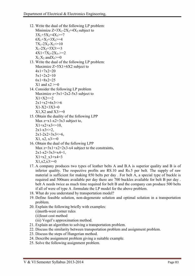
Department of Electrical & Electronics Engineering,
V & VI Semester Syllabus 2013-2014 Page 83
12. Write the dual of the following LP problem: Minimize Z=3X1-2X2+4X3 subject to 3X1+5X2+4X3>=7 6X1+X2+3X3>=4 7X1-2X2-X3<=10 X1-2X2+5X3>=3 4X1+7X2-2X3=>=2 X1,X2 andX3>=0
13. Write the dual of the following LP problem: Maximize Z=5X1+6X2 subject to 4x1+7x2=20 5x1+2x2=10 6x1+8x2=25 X1 and x2 >=0
14. Consider the following LP problem Maximize z=3x1+2x2-5x3 subject to X1+X2<=2 2x1+x2+6x3<=6 X1-X2+3X3=0 X1,X2 and X3>=0
15. Obtain the duality of the following LPP Max z=x1-x2+3x3 subject to, X1+x2+x3<=10, 2x1-x3<=2, 2x1-2x2+3x3<=6, X1, x2, x3>=0
16. Obtain the dual of the following LPP Max z=3x1+x2+2x3-x4 subject to the constraints, 2x1-x2+3x3+x4=1, X1+x2_x3+x4=3 X1,x2,x3>=0
17. A company produces two types of leather belts A and B.A is superior quality and B is of inferior quality. The respective profits are RS.10 and Rs.5 per belt. The supply of raw material is sufficient for making 850 belts per day . For belt A, a special type of buckle is required and 500nare available per day there are 700 buckles available for belt B per day . belt A needs twice as much time required for belt B and the company can produce 500 belts if all of were of type A .formulate the LP model for the above problem.
18. What do you understand by transportation model? 19. Define feasible solution, non-degenerate solution and optimal solution in a transportation
problem. 20. Explain the following briefly with examples:
(i)north-west corner rules (ii)least cost method (iii) Vogel’s approximation method.
21. Explain an algorithm to solving a transportation problem. 22. Discuss the similarity between transportation problem and assignment problem. 23. Discuss the steps of Hungerian method. 24. Describe assignment problem giving a suitable example. 25. Solve the following assignment problem.
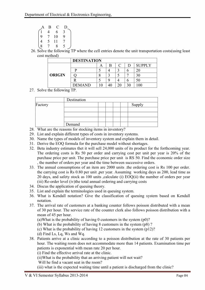
Department of Electrical & Electronics Engineering,
V & VI Semester Syllabus 2013-2014 Page 84
A B C D 1 4 6 3 9 7 10 9 4 5 11 7 8 7 8 5
26. Solve the following TP where the cell entries denote the unit transportation costs(using least cost method)
DESTINATION ORIGIN
A B C D SUPPLY P 5 4 3 6 20 Q 8 3 5 7 30 R 5 9 4 6 50 DEMAND 10 40 20 30 100
27. Solve the following TP.
Destination Factory Supply
Demand 28. What are the reasons for stocking items in inventory? 29. List and explain different types of costs in inventory systems. 30. Name the types of models of inventory system and explain them in detail. 31. Derive the EOQ formula for the purchase model without shortages. 32. Beta industry estimates thet it will sell 24,000 units of its product for the forthcoming year.
The ordering costs is Rs 50 per order and carrying cost per unit per year is 20% of the purchase price per unit. The purchase price per unit is RS 50. Find the economic order size , the number of orders per year and the time between successive orders.
33. The annual consumptions of an item are 2000 units .the ordering cost is Rs 100 per order. the carrying cost is Rs 0.80 per unit ,per year. Assuming working days as 200, lead time as 20 days, and safety stock as 100 units ,calculate (i) EOQ(ii) the number of orders per year (iii) Re-order level (iv)the total annual ordering and carrying costs
34. Discus the application of queuing theory. 35. List and explain the terminologies used in queuing system. 36. What is Kendall notation? Give the classification of queuing system based on Kendall
notation. 37. The arrival rate of customers at a banking counter follows poisson distributed with a mean
of 30 per hour. The service rate of the counter clerk also follows poisson distribution with a mean of 45 per hour. (a)What is the probability of having 0 customers in the system (p0)? (b) What is the probability of having 8 customers in the system (p8) ? (c) What is the probability of having 12 customers in the system (p12)? (d) Find Ls, Lq, Ws and Wq.
38. Patients arrive at a clinic according to a poisson distribution at the rate of 30 patients per hour. The waiting room does not accommodate more than 14 patients. Examination time per patients is exponential with mean rate 20 per hour. (i) Find the effective arrival rate at the clinic. (ii)What is the probability that an arriving patient will not wait? Will he find a vacant seat in the room? (iii) what is the expected waiting time until a patient is discharged from the clinic?

Department of Electrical & Electronics Engineering,
V & VI Semester Syllabus 2013-2014 Page 85
39. A stenographer has 5 persons for whom she performs stenographic work. Arrival rate is poisson and service times are exponential. Average arrivals rate is 4 per hour with an average service time of 10 minutes. Find, (i)the average waiting time of an arrival (ii)the average length of waiting line (iii)the average time on arrival spent in system.
40. Define project and give some application areas of project management. explain different phases of project management.
41. Distinguish between CPM and PERT. 42. Define the following :(a)total float,(b) free float ,and(c)critical path. 43. What are the time estimates used in PERT? 44. Consider the following data of a project. Duration (weeks) Activity Predecessors
a m b A - 3 5 8 B - 6 7 9 C A 4 5 9 D B 3 5 8 E A 4 6 9 F C,D 5 8 11 G C,D,E 3 6 9 H F 1 2 9 45. Explain the following terminologies of game theory
(a) Players (b) Strategy (c) Maximum principle (d) Minimax principle (e) Saddle point (f) Value of the game (g) Two person zero sum game (h) Dominance property
46. The following table gives the running costs per year and resale price of a certain equipment, whose purchase price is Rs.5,000
Year 1 2 3 4 5 6 7 8 Running cost 1500 1600 1800 2100 2500 2900 3400 4400 Resale value 3500 2500 1700 1200 800 500 500 500
In what year is the replacement due? 47. The following table gives the running cost per year and resale price of a certain machine,
whose purchase price is Rs.50,000. Year 1 2 3 4 5 6 7 8
Running cost(in 1000) 15 16 18 21 25 29 43 40 Resale value (in 1000) 35 25 17 12 8 5 5 5
48. List and explain different types of maintenance. Discuss the reasons for replacements. 49. Define economic life of equipment.

Department of Electrical & Electronics Engineering,
V & VI Semester Syllabus 2013-2014 Page 86
Lesson Plan Unit-I
1. Introduction: Definition, scope of Operations Research (O.R), 2. limitations, OR Models, 3. Characteristics and phases of OR. 4. Mathematical formulation of L.P. 5. Problems, Graphical 6. Problems, Graphical 7. Solution methods. 8. Linear Programming Problems: The simplex method - slack 9. surplus , Concept of duality, Dual simplex method, degeneracy
Unit-II 1. Transportation Problem: Formulation of transportation model, 2. Basic feasible solution using different methods, 3. Optimality Methods, 4. Unbalanced transportation problem, 5. Degeneracy in transportation problems, 6. Applications of Transportation problems. 7. Assignment Problem: Formulation, 8. maximization, 9. unbalanced assignment,
10. traveling salesman problem 11. traveling salesman problem 12. Numerical Problems
Unit-III 1. Inventory: Deterministic models with and without shortages; 2. replenishment, mean time, 3. ordering cost, carrying cost, 4. Economic order quantity(EOQ), 5. Queuing Theory 6. Queuing system and their characteristics 7. The M/M/1 Queuing system, 8. Steady state performance, 9. analysis of M/M/1 queuing model
Unit-IV 1. PERT-CPM Techniques: Network construction, 2. determining critical path, 3. floats, scheduling by network, 4. project duration, 5. variance under probabilistic models, 6. variance under probabilistic models 7. prediction of date of completion, 8. prediction of date of completion 9. crashing of simple networks. 10. crashing of simple networks
Unit-V 1. Game Theory: Formulation of games, 2. Two person-Zero sum game, 3. Two person-Zero sum game 4. games with and without saddle point, 5. games with and without saddle point

Department of Electrical & Electronics Engineering,
V & VI Semester Syllabus 2013-2014 Page 87
6. Graphical solution (2x n , m x 2 game), 7. Dominance property. 8. Replacement problems: Replacement of machines with considering value of money group
replacement problems 9. Replacement of machines without considering value of money group replacement problems
Course Articulation Matrix (CAM)
Course Outcome – CO Program Outcome (ABET/NBA-(3a-k))
a b c d e f g h i j k
1 Formulate and solve linear programming models
L1
L
H
L
-
L
-
L
-
-
H
L
2 Solve transportation and waiting line models L2
L
H
L
-
L
-
L
-
-
-
L
3 Obtain PERT network and recognize Critical path for a given project L3
L L
L
-
L
-
L
-
-
-
L
4 Apprehend proper strategy for a given game L4 L
H
L
M
L
-
L
-
M
-
L
5 Recognize the replacement period of a machine/equipment and EOQ L1
L H
L
L
L
-
L
-
M
-
L
L-Low, M-Moderate, H-High
Course Assessment Matrix (CAM)
Course Outcome – CO Program Outcome (ABET/NBA-(3a-k))
a b c d e f g h i j k
1 Formulate and solve linear programming models
L1 1 3 1
- 1 - 1
- -
3 1
2 Solve transportation and waiting line models L2 1 3 1
- 1 - 1
- -
- 1
3 Obtain PERT network and recognize Critical path for a given project L3 1 3 1
- 1 - 1
- -
- 1
4 Apprehend proper strategy for a given game L4 1 2 1 2 1 - 1
- 2
- 1
5 Recognize the replacement period of a machine/equipment and EOQ L1 1 3 1 1 1
- 1 -
2
- 1
1-Low, 2-Moderate, 3-High

Department of Electrical & Electronics Engineering,
V & VI Semester Syllabus 2013-2014 Page 88
Course Code Title: Fuzzy Logic Systems Course Code: P13EE664 Semester: VI L-T-P-H: 4-0-0-4 Credits – 4 Contact period : Lecture: 52 Hrs., Exam 3 Hrs. Weightage:CIE:50; SEE:50
Course Learning Objectives (CLOs) This course aims to 1. Provide an understanding of the basic mathematical elements of the theory of fuzzy sets. 2. Provide an emphasis on the differences and similarities between fuzzy sets and classical sets
theories. 3. Cover fuzzy logic inference with emphasis on their use in the design of intelligent or
humanistic systems. 4. Provide a brief introduction to fuzzy arithmetic concepts. 5. Provide an insight into fuzzy inference applications in the area of control and robotics
Course content
Unit-I a) Classical / Crisp sets and Fuzzy sets: Classical sets and Operations on Classical Sets, Properties of Classical Sets; Fuzzy sets – Properties of Fuzzy sets, Operations in Fuzzy Sets. b) Fuzzy Logic in Control Engineering: Introduction, Control system Design Problem, Fuzzy Logic Control (FLC) system Block Diagram - Architecture and Operation of FLC System. Examples of Control design. FLC System Models. Applications of FLC systems. 10 Hrs.
Unit-II Classical relations and fuzzy relations: Cartesian Product of Relations, Classical/Crisp relations, Fuzzy Relations, Operations on Fuzzy Relations, Properties of Fuzzy Relations, Fuzzy Cartesian Product and Composition. Tolerance and Equivalence Relations - Crisp Tolerance and Equivalence Relations, Fuzzy Tolerance and Equivalence Relations. The Extension Principle. 10 Hrs.
Unit-III Membership functions: Introduction, Features of Membership Functions, Fuzzification, Methods of Membership Value Assignments, and Defuzzification to Crisp sets, λ - Cuts (alpha –cuts) for Fuzzy Relations. Defuzzification methods – Max-membership principle, Centroid method, Weighted Average Method, Mean-Max membership, Center of Sums, and Center of Largest area, First and Last of Maxima. 12 Hrs.
Unit-IV Theory of approximate reasoning: Linguistic Variables, Linguistic Hedges, Fuzzy rule Based Systems, Fuzzy Proportions, Fuzzy if then Statements, Inference rules, Compositional rule of inference. Fuzzy Inference Systems (FIS) - Construction and Working Principals of FIS. Methods of FIS – Mamdani FIS, Sugino FIS, Takagi-Sugino fuzzy model. Comparison between Mamdani and Sugino method. 10 Hrs.
Unit-V Fuzzy knowledge based controllers (FKBC): Basic concept structure of FKBC, Choice of Membership Functions, Scaling Factors, Rules, Fuzzification and Defuzzification Procedures. Simple Applications of FKBC. 10 Hrs. Text Books: 1. Timothy J. Ross, Fuzzy logic with Engineering applications,
McGraw-Hill/Wiley IndiaPublications.2nd Edition. 2009. 2. D. Driankar, H. Hellendoom and M. ReinfrankNarosa An introduction
to Fuzzy control, Publishers India, 1996. (Reprint 2009) Reference Books: 1. N.Shivanandam, S.N.Deepa,Principles of Soft Computing,
Wiley India (pvt) Ltdpublications, First edition 2007. 2. R. R. Yaser and D. P. Filer John WileyEssentials of Fuzzy modeling and Control, 1994

Department of Electrical & Electronics Engineering,
V & VI Semester Syllabus 2013-2014 Page 89
Course Outcomes
After learning all the units of the course, the student is able to CO1. Distinguish between the crisp set and fuzzy set concepts. CO2. Draw a parallelism between crisp set operations and fuzzy set operations
through the use of characteristic and membership functions respectively. CO3. Become familiar with fuzzy relations and the properties of these relations. CO4. Become knowledgeable of conditional fuzzy propositions and
fuzzy inference systems. CO5. Become aware of the application of fuzzy inference in the area of control
Topic Learning Objectives After learning all the topics of UNIT-I, the student is able to
1. Understand the basic concepts of Operations on Classical Sets and fuzzy sets 2. Explain the Properties of Classical and fuzzy Sets 3. Analyze Control system Design Problem. 4. Explain the concept of architecture and Operation of FLC System 5. Explain FLC System Models and applications of FLC systems
After learning all the topics of UNIT-II, the student is able to
1. Explain the concept of Cartesian Product of Relations and Classical/Crisp relations 2. Explain the Operations on and Properties of Fuzzy Relations 3. Analyze the Tolerance and Equivalence Relations and Equivalence Relations 4. Describe the Fuzzy Tolerance and Equivalence Relations 5. Explain the Extension Principle
After learning all the topics of UNIT-III, the student is able to
1. Describe the features of Membership Functions. 2. Describe the different methods of Membership Value Assignments. 3. Explain the different defuzzification methods. 4. Explain the concept of defuzzification to Crisp sets and λ - Cuts (alpha –cuts) for Fuzzy
Relations After learning all the topics of UNIT-IV, the student is able to
1. Describe Linguistic Variables, Linguistic Hedges 2. Explain Fuzzy rule Based Systems, Fuzzy Proportions 3. Explain the concept of Fuzzy if then Statements, Inference rules. 4. Explain the concept of Fuzzy Inference Systems (FIS) 5. Explain the construction and Working Principals of FIS 6. Explain different methods of FIS – Mamdani FIS, Sugino FIS, Takagi-Sugino fuzzy model.
Comparison between Mamdani and Sugino method After learning all the topics of UNIT-V, the student is able to
1. Explain basic concept structure of FKBC. 2. Explain about choice of Membership Functions. 3. Explain the concept of Fuzzification and Defuzzification Procedures. 4. Explain Simple Applications of FKBC.
Review questions.
1. Differentiate between probability and fuzzy logic? 2. What is fuzzy expert system?

Department of Electrical & Electronics Engineering,
V & VI Semester Syllabus 2013-2014 Page 90
3. What is adaptive fuzzy system? 4. What are conditions for neural net applications? 5. What is possibility theory? 6. What is fuzzy modeling? 7. What is perception? 8. Explain properties of fuzzy sets with example. 9. What are fuzzy set operations?
10. Compare various defuzzification methods. 11. Discuss various Neuro-fuzzy signal analyses for washing machines. 12. Define fuzzy set theory. How fuzzy sets are different from crisp sets? Give at least two
examples. 13. Explain the following with example. i) Fuzzy union ii) fuzzy intersection iii) Fuzzy
complement 14. With suitable example, explain the extension principle. 15. Explain graphical mamdani (max-min) implication method with crisp and fuzzy inputs with
example. 16. What do you understand by cluster? Explain fuzzy C-means clustering. 17. Write a note on membership value assignment. 18. Write a note on structures for fuzzy if-then rule. 19. Write a note on fuzzy ordering. 20. Explain lambda cuts for fuzzy sets and fuzzy relations. 21. What do you mean by defuzzification? Explain the following methods of defuzzification.
i) centroid method ii) Weight average method. 22. Explain briefly the graphical techniques of inference. 23. Explain linguistic hedges. 24. Explain briefly fuzzy Bayesian decision method. 25. Write a note on FKBC. 26. Discuss features of a membership function. Explain with suitable diagrams. 27. What are different fuzzy relations? Explain with suitable examples. 28. Write a note on crisp and fuzzy tolerance and equivalence relations. 29. Define Fuzzy set operations and properties. 30. Draw the Venn diagrams for fuzzy set operations. 31. Write a note on linguistic variables and hedges. 32. Explain compositional rule of inference. 33. Explain the construction and working principles of fuzzy inference systems. 34. Write a note on the following. i) takagi-Sugino fuzzy model. ii) Mamdani FIS. 35. With neat block diagram, explain the architecture and operation of FLC system. 36. Write a brief note on applications of FLC systems. 37. Write a note on choice of membership functions. 38. Using your own intuition, develop fuzzy membership functions on the real line for the fuzzy
number “approximately 2 or approximately 8” using the following function shapes: i) Symmetric triangles. ii) Gaussian functions. iii) Trapezoids.
39. Determine the equivalent resistance of the circuitry shown below, where R1 and R2 are fuzzy sets describing the resistance of resistors R1 and R2 respectively, expressed in ohms. Since the resistors are in series they can be added arithmetically. Using the extension principle, find the equivalent resistance. Eeq=R1 + R2
40. Develop membership functions for the following linguistic phrases: i) Very heavy ii) Fairly heavy iii) Not very light.
41. Explain the operation of FLC system with neat block diagram,. 42. Write a note on Fuzzy set operations properties. 43. Write a note on Fuzzy set properties.

Department of Electrical & Electronics Engineering,
V & VI Semester Syllabus 2013-2014 Page 91
44. What is FKBC. Explain. 45. Write a note on inference compositional rule. 46. Explain about different types of membership functions. 47. Define cluster? Explain fuzzy C-means clustering 48. Explain the extension principle with suitable example. 49. What is fuzzy set theory. How fuzzy sets are different from crisp sets? 50. Explain the following with example. i) fuzzy intersection ii) Fuzzy complement.
Lesson Plan
Unit-I 1. Classical sets and Operations on Classical Sets 2. Properties of Classical Sets. 3. Properties of Fuzzy sets. 4. Operations in Fuzzy Sets 5. Fuzzy Logic in Control Engineering: Introduction, Control system Design Problem 6. Fuzzy Logic Control (FLC) system Block Diagram. 7. Architecture and Operation of FLC System. 8. Examples of Control design. FLC System Models. 9. FLC System Models
10. Applications of FLC systems Unit-II
1. Cartesian Product of Relations 2. Classical/Crisp relations 3. Fuzzy Relations. 4. Operations on Fuzzy Relations. 5. Properties of Fuzzy Relations. 6. Fuzzy Cartesian Product and Composition. 7. Tolerance and Equivalence Relations. 8. Crisp Tolerance and Equivalence Relations 9. Fuzzy Tolerance and Equivalence Relations
10. The Extension Principle. Unit-III
1. Membership functions:Introduction. 2. Features of Membership Functions 3. Fuzzification, Methods of Membership Value Assignments. 4. Defuzzification to Crisp sets. 5. λ - Cuts (alpha –cuts) for Fuzzy Relations. 6. Defuzzification methods – Max-membership principle. 7. Centroid method. 8. Weighted Average Method 9. Mean-Max membership.
10. Center of Sums, and Center of Largest area 11. Center of Sums, and Center of Largest area 12. First and Last of Maxima
Unit-IV 1. Theory of approximate reasoning: Linguistic Variables 2. Linguistic Hedges 3. Fuzzy rule Based Systems 4. Fuzzy Proportions 5. Fuzzy if then Statements, Inference rules 6. Compositional rule of inference

Department of Electrical & Electronics Engineering,
V & VI Semester Syllabus 2013-2014 Page 92
7. Fuzzy Inference Systems (FIS) - Construction and Working Principals of FIS 8. Methods of FIS – Mamdani FIS, Sugino FIS 9. Takagi-Sugino fuzzy model
10. Comparison between Mamdani and Sugino method Unit-V
1. Introduction to Fuzzy knowledge based controllers 2. Basic concept structure of FKBC 3. Choice of Membership Functions 4. Scaling Factors. 5. Scaling rules 6. Fuzzification procedures 7. Defuzzification Procedures. 8. Simple Applications of FKBC 9. Applications in robotics.
10. Applications in control systems.
Course Articulation Matrix (CAM) Course Outcome – CO Program Outcome (ABET/NBA-(3a-k))
a b c d e f g h i j k
1 Distinguish between the crisp set and fuzzy set concepts.
L4 H M L - - - - - - - -
2
Draw a parallelism between crisp set operations and fuzzy set operations through the use of characteristic and membership functions respectively.
L2 L M H - L - - - - - -
3 Become familiar with fuzzy relations and the properties of these relations.
L6 H M H L - - - M - - -
4 Become knowledgeable of conditional fuzzy propositions and fuzzy inference systems.
L5 H M L - - - - - - - L
5 Become aware of the application of fuzzy inference in the area of control.
L1 L M H - L - - - L - L
L-Low, M-Moderate, H-High Course Assessment Matrix (CAM)
Course Outcome – CO Program Outcome (ABET/NBA-(3a-k)) a b c d e f g h i j k
1 Distinguish between the crisp set and fuzzy set concepts.
L4 3 2 1 - - - - - - - -
2
Draw a parallelism between crisp set operations and fuzzy set operations through the use of characteristic and membership functions respectively.
L2 1 2 3 - 1 - - - - - -
3 Become familiar with fuzzy relations and the properties of these relations. L6 3 2 3 1 - - - 2 - - -
4 Become knowledgeable of conditional fuzzy propositions and fuzzy inference systems. L5 3 2 1 - - - - - - - 1
5 Become aware of the application of fuzzy inference in the area of control.
L1 1 2 3 - 1 - - - 1 - 1
1-Low, 2-Moderate, 3-High

Department of Electrical & Electronics Engineering,
V & VI Semester Syllabus 2013-2014 Page 93
Course Title: Control Systems and DSP Laboratory Course Code: P13EEL67 Semester: VI L:T:P:H-0-0-3-3 Credits – 1.5 Contact Period: Lecture: 39 Hrs., Exam: 3 Hrs. Weight age: CIE: 50, SEE: 50
Course Learning Objectives (CLOs)
This course aims to Control system Lab: 1. Provide the basic knowledge of how to use MATLAB for Control System & DSP concepts. 2. Simulate a typical second order system and to determine the step response. 3. Study the Compensating networks viz., Lag, Lead and Lag- lead compensating networks. 4. Study the effect of P, PI, PD and PID controller. 5. Draw the speed – torque characteristic of a two - phase A.C. servomotor and D.C. servomotor. 6. Draw the Root locus and Bode for the given transfer function. 7. Self Study Experiments
DSP - Lab: 8. Illustrate the Verification of sampling theorem. 9. Determine the impulse response and step response of a given system. 10. Determine the Circular convolution and Linear convolution of two given sequences. 11. Compute the N - point DFT of a given sequence and IDFT for given DFT points. 12. Design of Butterworth Low Pass IIIR filter 13. Self Study Experiments
Course Content
Control Systems Laboratory 1. (a) Simulation of a typical second order system and determination of step response.
(b) Evaluation of time- domain specifications and verify using MATLAB. 2. Study of Compensating networks – determination of the transfer function and the frequency
response characteristic of Lag, Lead and Lag- lead compensating networks. 3. To study the effect of P, PI, PD and PID controller on the step response of a feedback control
system (using process control simulator). 4. Experiment to draw the speed – torque characteristic of a two - phase A.C. servomotor and
D.C. servomotor 5. (a) To draw the Root locus for a given transfer function and to show its breakaway points and
imaginary axis crossover point and to obtain the range of K for the stability of the system and verification using MATLAB. (b) Obtain the Gain cross over frequency, phase cross over frequency, phase margin and gain margin for a given transfer function by drawing Bode plots. Verify the same using MATLAB
Digital signal processing (DSP) Laboratory 1. Verification of sampling theorem 2. Solving of a difference equation to find the impulse response and step response. 3. Compute convolutions: (i) Linear convolution of two given sequences
(ii) Circular convolution of two given sequences 4. (i)Computation of N - point DFT of a given sequence and to plot magnitude and
phase spectrum.(ii)Computation of N - point IDFT of a given DFT points. 5. Design and implementation of Butterworth LPF (IIR- filter) to meet given specifications.
Course Outcome
After conducting all the experiments the student is able to 1. Analyze the performance of any second order system. (L4)

Department of Electrical & Electronics Engineering,
V & VI Semester Syllabus 2013-2014 Page 94
2. Analyze the effects and limitations of Lag, Lead, Lag-Lead compensators. (L4) 3. Explain the importance of different types of PID controllers.(L3) 4. Explain the behavior of AC &DC Servo motors. (L3) 5. Analyze the performance and stability of lower and higher systems.(L4) 6. Demonstrate the Verification of sampling theorem. (L3) 7. To determine the impulse response and step response of a given system. (L5) 8. Compute the Circular and Linear convolution of two given sequences. (L3) 9. Compute the N - point DFT and IDFT (L4)
10. Design of Butterworth Low Pass IIR filter (L5)

Department of Electrical & Electronics Engineering,
V & VI Semester Syllabus 2013-2014 Page 95
Course Articulation Matrix (CAM) Course Outcome – CO Program Outcome (ABET/NBA-(3a-k))
a b c d e f g h i j k
1 Analyze the performance of any second order electrical system.
L4 L L - - - - - - - - L
2 Analyze the effects and limitations of Lag, Lead, and Lag-Lead compensating networks Lag-Lead compensators.
L4 L L L - - - - - - - L
3 Explain the importance of different types of PID controllers
L3 L L - - - - - - - - L
4 Explain the behavior of AC &DC Servo motors. L3 L L - - - - - - - - L
5 Analyze the performance and stability of lower and higher systems
L4 L L L - - - - - - - L
6 Demonstrate the Verification of sampling theorem. L3 M M - - - - - - - M
7 Determine the impulse response and step response of a given system
L5 M M - - - - - - - - M
8 Compute the Circular and Linear convolution of two given sequences.
L3 M M - - - - - - - - M
9 Compute the N - point DFT and IDFT L4 M M - - - - - - - - M 10 Design of Butterworth Low Pass IIR filter L5 M M - - - - - - - - M L-Low, M-Moderate, H-High
Course Assessment Matrix (CAM) Course Outcome – CO Program Outcome (ABET/NBA-(3a-k))
a b c d e f g h i j k
1 Analyze the performance of any second order electrical system.
L4 1 1 - - - - - - - - 1
2 Analyze the effects and limitations of Lag, Lead, and Lag-Lead compensating networks Lag-Lead compensators.
L4 1 1 1 - - - - - - - 1
3 Explain the importance of different types of PID controllers
L3 1 1 - - - - - - - - 1
4 Explain the behavior of AC &DC Servo motors. L3 1 1 - - - - - - - - 1
5 Analyze the performance and stability of lower and higher systems
L4 1 1 1 - - - - - - - 1
6 Demonstrate the Verification of sampling theorem. L3 2 2 - - - - - - - 2
7 Determine the impulse response and step response of a given system
L5 2 2 - - - - - - - - 2
8 Compute the Circular and Linear convolution of two given sequences.
L3 2 2 - - - - - - - - 2
9 Compute the N - point DFT and IDFT L4 2 2 - - - - - - - - 2 10 Design of Butterworth Low Pass IIR filter L5 2 2 - - - - - - - - 2 1-Low, 2-Moderate, 3-High

Department of Electrical & Electronics Engineering,
V & VI Semester Syllabus 2013-2014 Page 96
Course Title: Microcontroller and PLC Lab Course Code: P13EEL68 Semester: VI L:T:P:H-0-0-3-3 Credits – 1.5 Contact Period: Lecture: 39 Hrs., Exam: 3 Hrs. Weight age: CIE: 50%, SEE: 50%
Course Learning Objectives (CLOs) This course aims to:
1. To provide practical knowledge about writing program in assembly level language and executing programs using Microcontroller kit
2. To provide practical knowledge about interfacing the hardware to Microcontroller kit 3. To provide practical knowledge of ladder programming using PLC kit 4. To learn interfacing of programmable logic controllers with external devices
List of Experiments: 1. Addition, Subtraction, Multiplication & Division of 8-bit data 2. Addition &Subtraction of 16 bit data 3. To find the largest and smallest of 8-bit number in a given array 4. Arranging numbers in Ascending & Descending order in a given array 5. Code conversions: Binary to gray , ASCII to BCD, Hexadecimal to decimal & vice versa 6. a) To find the number of 1’s & 0’s & +ve and –ve number in an array
b) Sorting of even and odd numbers separately 7. DC Motor & Stepper Motor interface with microcontroller 8. Elevator interface with microcontroller 9. Speed control of Induction Machine using Programmable logic controller 10. Speed control of special machine (Brushless DC machine)using
Programmable logic controller 11. Speed control of DC shunt Machine using Programmable logic controller 12. Speed control of Permanent magnet synchronous Machine using
Programmable logic controller 13. Self-study experiment
Course outcome: CO1. Writing program for Addition, Subtraction, Multiplication &
Division of 8-bit data & 16 bit number using assembly level language CO2. writing program to arrange the number in even or odd ; to sort in ascending or
descending order ; code conversion ; finding 0’s & 1’s CO3. Hardware interfacing to Microcontroller kit CO4. Predict PLC operation based on ladder logic diagrams CO5. Program a PLC to perform various control functions by interfacing
with different types of motors Topic learning Objectives (TLOs):
1. To analyze and to execute the programs of Addition, Subtraction, Multiplication & Division of 8-bit data & 16 bit
2. To analyze and to execute the programs of finding find the largest and smallest of 8-bit number in a given array ; Arranging numbers in Ascending & Descending order in a given array
3. To analyze and to execute the programs of different code conversions ; sorting even and odd ; finding 0’s & 1’s
4. To interface and to execute the elevator program using microcontroller kit 5. To analyze ladder programming in PC by connecting with PLC kit 6. To analyze speed and direction of rotation of given motor by interfacing with PLC Kit and
by writing Ladder Program

Department of Electrical & Electronics Engineering,
V & VI Semester Syllabus 2013-2014 Page 97
Course Articulation Matrix (CAM)
Course Outcome – CO Program Outcome (ABET/NBA-(3a-k))
a b c d e f g h i j k
1 Writing program for Addition, Subtraction, Multiplication & Division of 8-bit data & 16 bit number using assembly level language
L2 M M L - M - - L - M -
2 writing program to arrange the number in even or odd ; to sort in ascending or descending order ; code conversion ; finding 0’s & 1’s
L2 L H M - M - - - - - -
3 Hardware interfacing to Microcontroller kit L3 L L M - L M - - - - H
4 Predict PLC operation based on ladder logic diagrams
L3 M H L M L - - - - - M
5 Program a PLC to perform various control functions by interfacing with different types of motors
L4 M H L M L - - - - - M
L-Low, M-Moderate, H-High
Course Assessment Matrix (CAM)
Course Outcome – CO Program Outcome (ABET/NBA-(3a-k))
a b c d e f g h i j k
1 Writing program for Addition, Subtraction, Multiplication & Division of 8-bit data & 16 bit number using assembly level language
L2 2 2 1 - 2 - - 1 - 2 -
2
writing program to arrange the number in even or odd ; to sort in ascending or descending order ; code conversion ; finding 0’s & 1’s
L2 1 3 2 - 2 - - - - - -
3 Hardware interfacing to Microcontroller kit L3 1 1 2 - 1 2 - - - - 3
4 Predict PLC operation based on ladder logic diagrams
L3 2 3 1 2 1 - - - - - 2
5 Program a PLC to perform various control functions by interfacing with different types of motors
L4 2 3 1 2 1 - - - - - 2
1-Low, 2-Moderate, 3-High