ee 742 chap. 7: wind power generation
TRANSCRIPT
EE 742Chap. 7: Wind Power Generation
Y. BaghzouzFall 2011
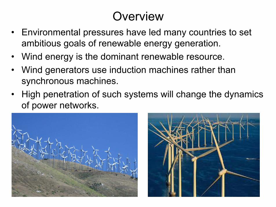
Overview• Environmental pressures have led many countries to set
ambitious goals of renewable energy generation.• Wind energy is the dominant renewable resource. • Wind generators use induction machines rather than
synchronous machines.• High penetration of such systems will change the dynamics
of power networks.

US Wind Resource Map
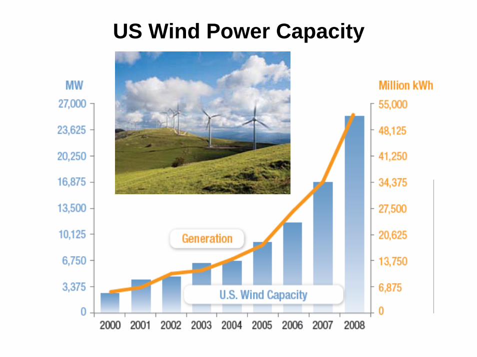
US Wind Power Capacity

Wind Power Outlook
• Top 4 wind Power Producers:– 1. China– 2. USA– 3. Germany– 4. Spain
• By early 2010, American wind plants were generating about 2% of U.S. electricity supply.
• A U.S. Department of Energy report analyzes a path to reaching 20% wind power by 2030.
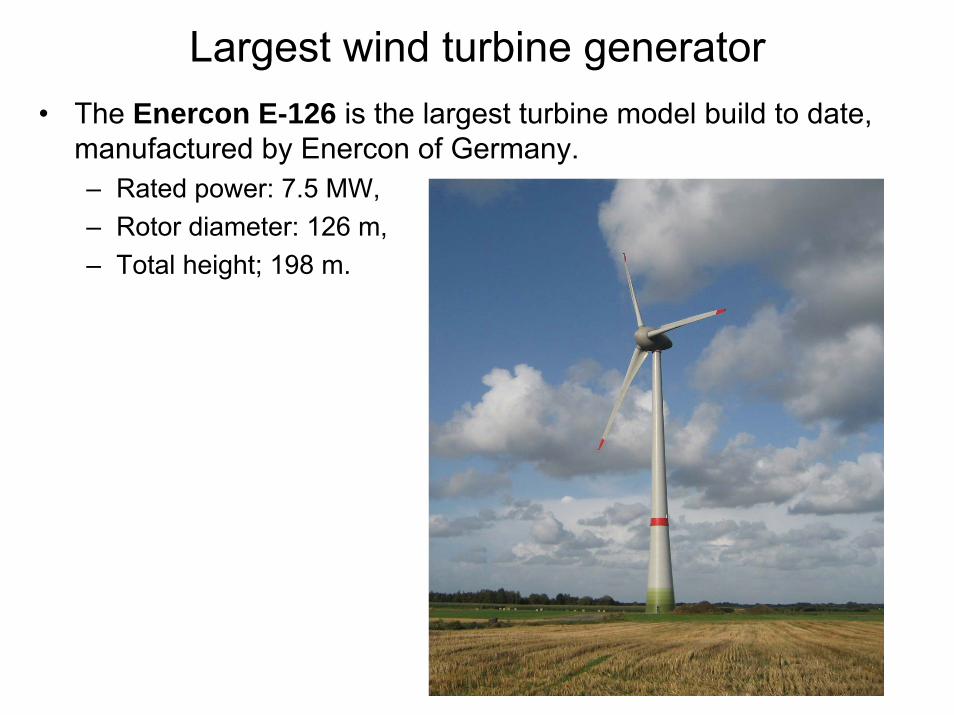
Largest wind turbine generator• The Enercon E-126 is the largest turbine model build to date,
manufactured by Enercon of Germany.– Rated power: 7.5 MW, – Rotor diameter: 126 m, – Total height; 198 m.
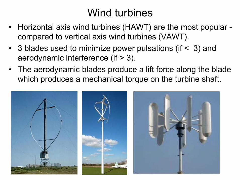
Wind turbines• Horizontal axis wind turbines (HAWT) are the most popular -
compared to vertical axis wind turbines (VAWT).• 3 blades used to minimize power pulsations (if < 3) and
aerodynamic interference (if > 3).• The aerodynamic blades produce a lift force along the blade
which produces a mechanical torque on the turbine shaft.

Typical arrangement of a wind turbine
• Typically, the low turbine speed (15-20 rpm) is stepped up to synchronous speed (e.g., 1,800 rpm) through a gear-box.
• The output shaft of the gear-box drives an induction machines.
• This generator is connected to the grid through a step-up transformer.
• A yaw system turns the turbine in the direction of the wind, and provides breaking.
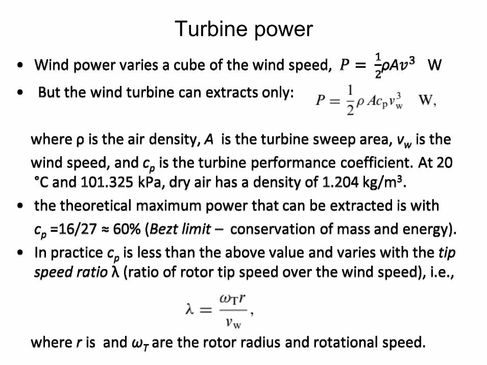
Turbine power

Turbine Power• A typical cp - λ curve is shown below and is unique to a
particular turbine design. Modern wind turbine design can reach 70-80% of the theoretical limit.
• To extract maximum power, the turbine must be operated at the peak of the curve (peak power tracking).
• For a given wind speed vw and the cp - λ characteristics, the turbine power can be calculated as a function of shaft speed.

Turbine Power• For a given turbine cp, the turbine power can be graphed
as a function of the wind speed as shown below.• The figure shows the cut-in speed (3-4 m/s), rated speed
(12.5 m/s), and shut down speed (around 25 m/s). • Turbines are tyically designed to withstand wind speeds of
up to 50 m/s (180 km/hr)

Power control• Some form of power control at high wind speeds is needed so that the
turbine does not exceed its rated speed. Two methods are available:– Passive stall control – normally used on fixed speed machines. In here the
turbine blades are designed so that the lift force on the blades reduces and the blade progressively goes into stall with increased wind speed.
– Active pitch control - in here, the pitch of the blade is changed to reduce the output power (requires feedback control signal such as rotational speed)
• See typical output power for fixed speed turbines (with passive stall control) and variable speed turbines (with active pitch control) below:
Pitch control vary angle of attack

Diameter and operating speeds of various wind turbine sizes (assuming rated speed of 12.5 m/s)

Wind annual distribution (with MAWS = 7 m/s) and annual energy yield by a 60 m diameter turbine (with rated speed of 12.5 m/s)
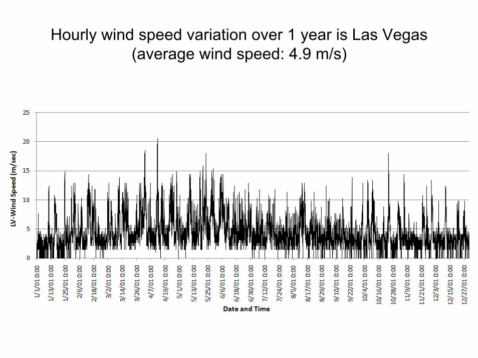
Hourly wind speed variation over 1 year is Las Vegas(average wind speed: 4.9 m/s)
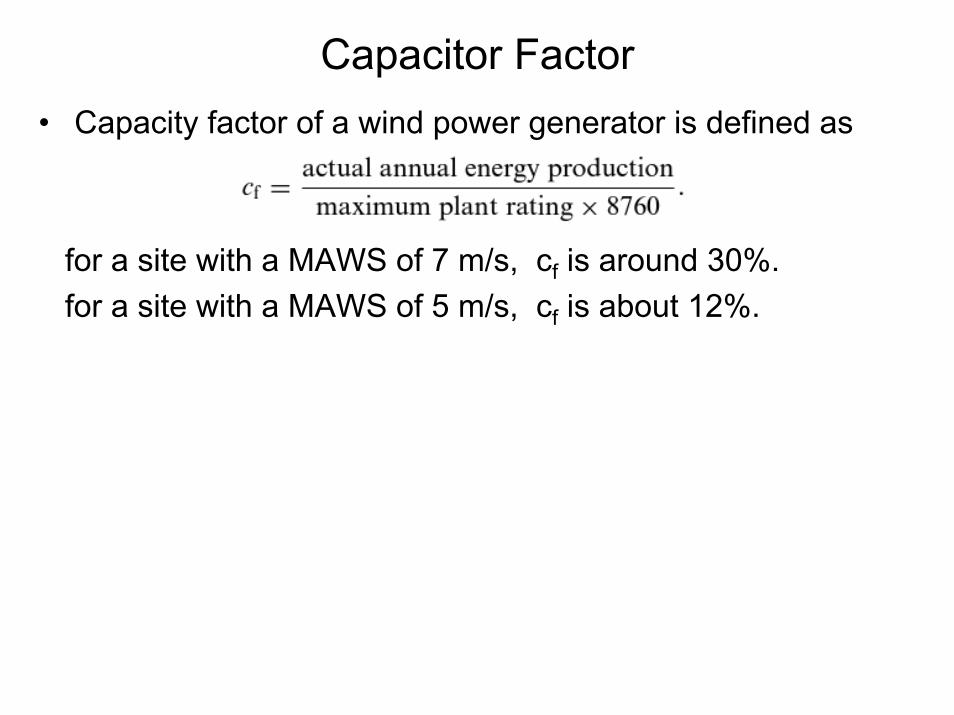
Capacitor Factor• Capacity factor of a wind power generator is defined as
for a site with a MAWS of 7 m/s, cf is around 30%.for a site with a MAWS of 5 m/s, cf is about 12%.

Wind intermittency: most important issue
Source: NREL
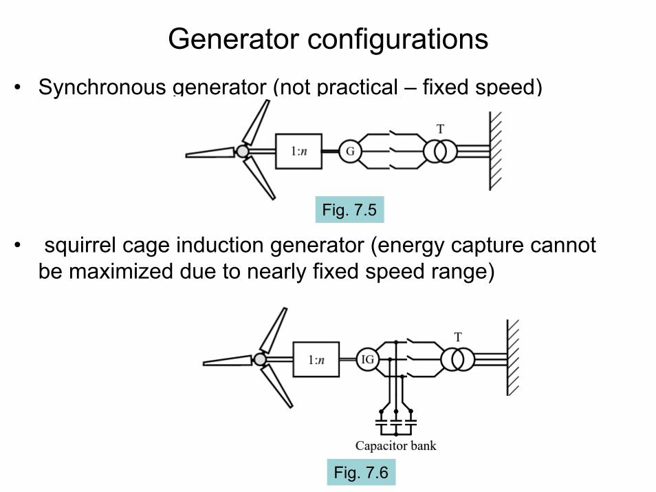
Generator configurations• Synchronous generator (not practical – fixed speed)
• squirrel cage induction generator (energy capture cannot be maximized due to nearly fixed speed range)
Fig. 7.6
Fig. 7.5
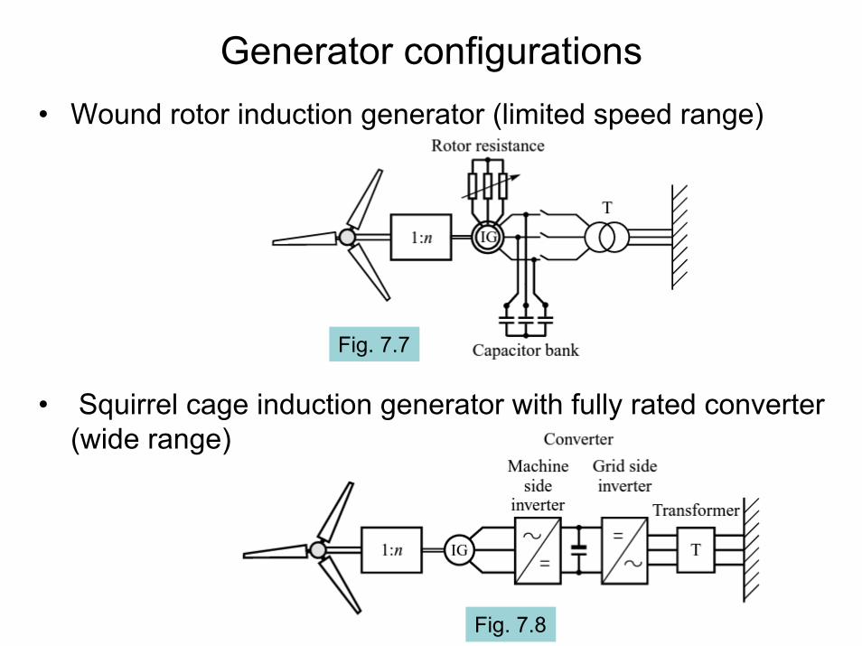
Generator configurations• Wound rotor induction generator (limited speed range)
• Squirrel cage induction generator with fully rated converter (wide range)
Fig. 7.8
Fig. 7.7

Generator configurations• Doubly-fed induction generator (partially rated converted)
speed limit (30%)
• Permanent magnet generator with fully rated converter (wide range)
Fig. 7.10
Fig. 7.9
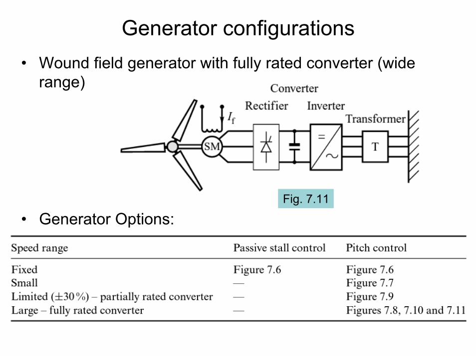
Generator configurations• Wound field generator with fully rated converter (wide
range)
• Generator Options:Fig. 7.11

Induction motor equivalent circuit

Torque-speed curve• Mechanical power delivered to the shaft:
• Mechanical torque:

Power flow in an induction machine
• If the losses in the stator winding resistance and iron cores are neglected, then the power supplied by the grid is the same as that supplied to the rotor.
• In the figure below, the directions are shown as positive for motor action (slip s is positive).
• for generator action (slip s is negative), Pm and Psreverse direction, while the rotor loss remains unchanged

Induction generator coupled to the grid• A synchronous generator is stiffly coupled to the network –
wind turbulence can large stress on the drive shaft. • An induction generator, on the other hand, is “softly”
coupled to the network as a it allows relative movement of the shaft speed.– For small slip values, the machine torque is proportional to speed
deviation (this is analogous to a mechanical damper):

• Refer to the equivalent circuit of an induction generator connected to a distribution line through a transformer (incorporate Xs and XT into X1, and Rsinto R1)
• The induction machine torque-slip curve determine the steady-state stability limit.
• The maximum (pull-out) torque determines the steady-state stability limit.
Induction generator coupled to the grid

• The maximum torque depends on X1 (including the system reactance) and supply voltage Vs:– A stiff system (i.e., small Xs) results in larger max. torque– A weak system (i.e., large Xs) results in a smaller max. torque– A drop in supply voltage results in a sharp drop in max. torque– A larger rotor resistance does not affect the max. torque, but
increases the slip at which the max. torque occurs.
Induction generator coupled to the grid

Induction generator with external rotor resistance
• This method allows and increase in speed variation.• The rated torque and current are the same, but this occurs
at a different slip value.• The gain in energy capture obtained by allowing more
speed variation should be balanced against reduced efficiency.
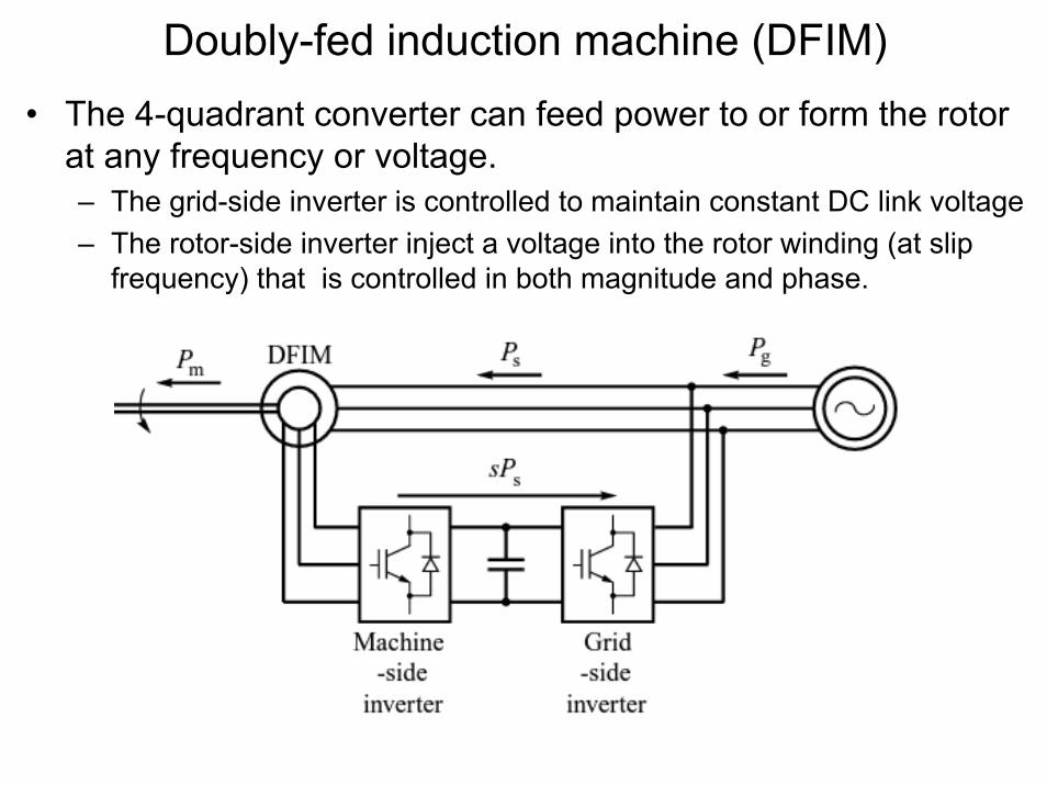
Doubly-fed induction machine (DFIM)• The 4-quadrant converter can feed power to or form the rotor
at any frequency or voltage.– The grid-side inverter is controlled to maintain constant DC link voltage– The rotor-side inverter inject a voltage into the rotor winding (at slip
frequency) that is controlled in both magnitude and phase.

DFIM Equivalent Circuit• If the injected voltage is in phase with the rotor current, this is
equivalent to adding a resistance R’ext to the rotor (= V’s/I2).• The rotor current and mechanical torque can be derived as
before. The slip can be written in terms of the injected voltage as

DFIM Equivalent Circuit• If the stator winding losses are neglected, the power supplied to
the machine is approximated by
• The second term depends on the polarity of the injected voltage (extracted from or delivered to the rotor )
• Further, if the rotor winding resistance is neglected, the Pg = Pm. (i.e., 100% efficiency)

DFIM as a synchronous generator• In a SG, the DC current is fed in the
rotor circuit to produce the synchronously rotating field.
• In the DFIM current is fed in the rotor circuit at slip frequency in order to produce the synchrnously rotating field.
• The voltage across the magnetizing reactance can be written as
where• Note that the equivalent circuit of a
DFIM now resembles that of a SG. Both the magnitude and phase of I2 (hence of E) by controlled by the injected voltage V’s in the rotor winding.

Phasor diagram of a DFIG as a SG
• I2 fully controls the magnitude and phase of E (while the field current in a SG controls only the magnitude of E).
• Machine complex power:
I2a controls P I2b controls Q

Control strategy of DFIG
Rotor current componentsin terms of P and Q:

Fully rated converter systems• The machine-side converter is generally operated to control the
generator torque loading at a particular speed (for max power) while the grid-side inverter is operated to control reactive power and maintain constant DC bus voltage.
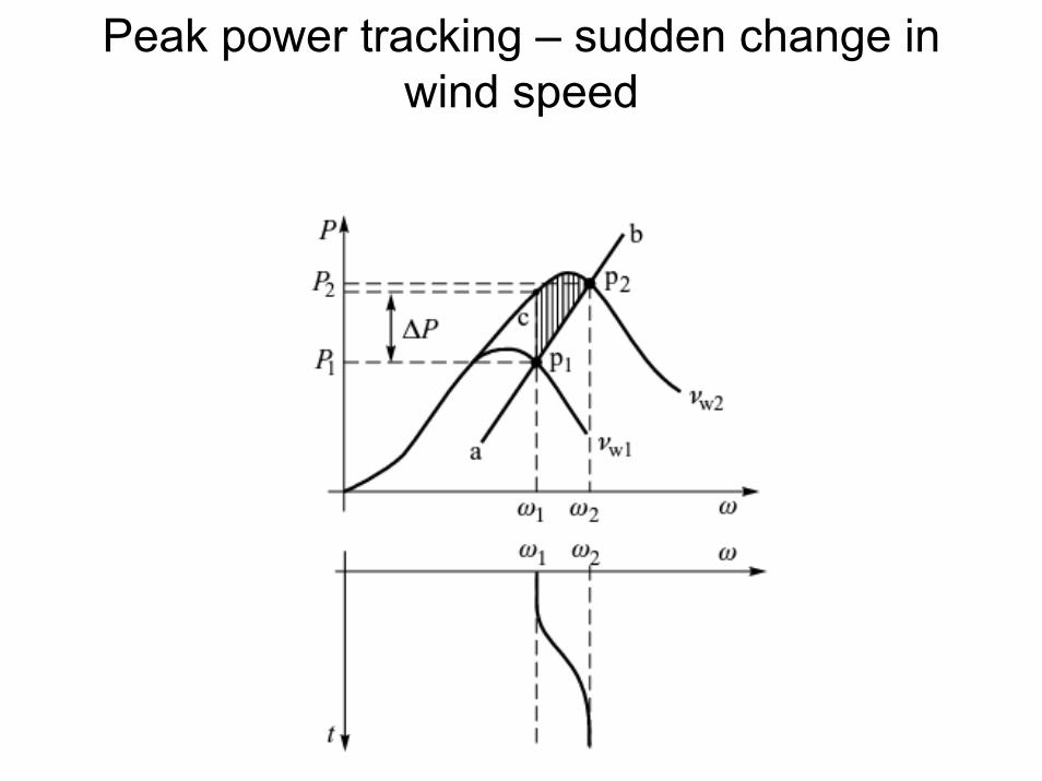
Peak power tracking – sudden change in wind speed
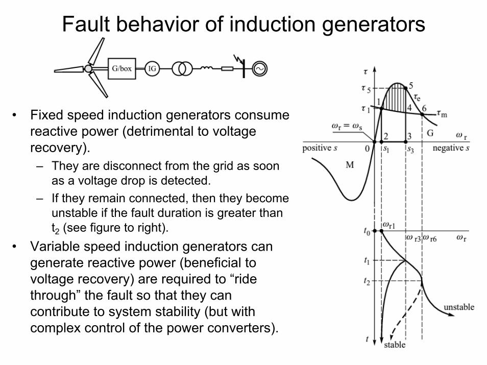
Fault behavior of induction generators
• Fixed speed induction generators consume reactive power (detrimental to voltage recovery).– They are disconnect from the grid as soon
as a voltage drop is detected.– If they remain connected, then they become
unstable if the fault duration is greater than t2 (see figure to right).
• Variable speed induction generators can generate reactive power (beneficial to voltage recovery) are required to “ride through” the fault so that they can contribute to system stability (but with complex control of the power converters).