edward w. brooke courthouse hvac system …
TRANSCRIPT
1 | P a g e 7 / 2 8 / 2 0 2 1
EDWARD W. BROOKE COURTHOUSE HVAC SYSTEM EVALUATION SUMMARY
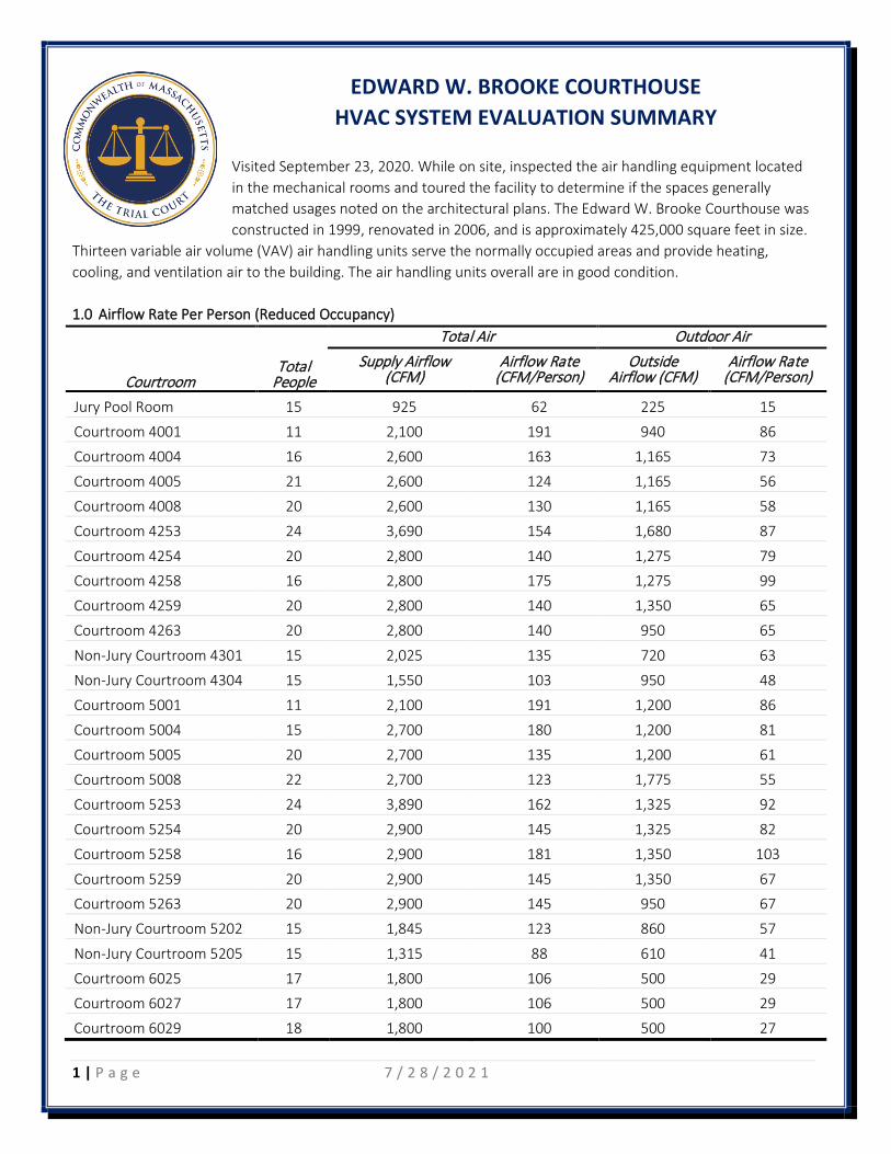
Visited September 23, 2020. While on site, inspected the air handling equipment located in the mechanical rooms and toured the facility to determine if the spaces generally matched usages noted on the architectural plans. The Edward W. Brooke Courthouse was constructed in 1999, renovated in 2006, and is approximately 425,000 square feet in size.
Thirteen variable air volume (VAV) air handling units serve the normally occupied areas and provide heating, cooling, and ventilation air to the building. The air handling units overall are in good condition. 1.0 Airflow Rate Per Person (Reduced Occupancy)
Total People
Total Air Outdoor Air
Courtroom Supply Airflow
(CFM) Airflow Rate
(CFM/Person) Outside
Airflow (CFM) Airflow Rate
(CFM/Person)
Jury Pool Room 15 925 62 225 15
Courtroom 4001 11 2,100 191 940 86
Courtroom 4004 16 2,600 163 1,165 73
Courtroom 4005 21 2,600 124 1,165 56
Courtroom 4008 20 2,600 130 1,165 58
Courtroom 4253 24 3,690 154 1,680 87
Courtroom 4254 20 2,800 140 1,275 79
Courtroom 4258 16 2,800 175 1,275 99
Courtroom 4259 20 2,800 140 1,350 65
Courtroom 4263 20 2,800 140 950 65
Non-Jury Courtroom 4301 15 2,025 135 720 63
Non-Jury Courtroom 4304 15 1,550 103 950 48
Courtroom 5001 11 2,100 191 1,200 86
Courtroom 5004 15 2,700 180 1,200 81
Courtroom 5005 20 2,700 135 1,200 61
Courtroom 5008 22 2,700 123 1,775 55
Courtroom 5253 24 3,890 162 1,325 92
Courtroom 5254 20 2,900 145 1,325 82
Courtroom 5258 16 2,900 181 1,350 103
Courtroom 5259 20 2,900 145 1,350 67
Courtroom 5263 20 2,900 145 950 67
Non-Jury Courtroom 5202 15 1,845 123 860 57
Non-Jury Courtroom 5205 15 1,315 88 610 41
Courtroom 6025 17 1,800 106 500 29
Courtroom 6027 17 1,800 106 500 29
Courtroom 6029 18 1,800 100 500 27

2 | P a g e 7 / 2 8 / 2 0 2 1
2.0 Recommendations Section Recommendation/Finding Action
2.1 Filter Efficiency
No actionable items identified Complete
2.2 Testing and Balancing RTB-1 Test and rebalance air handling unit minimum outside air flow rate Complete RTB-2 Rebalance system return air flow rate In-progess RTB-3 Increase outside air flow rate beyond minimum under non-peak
conditions Complete
RTB-4 Test and balance VAV box flow rates N/A RTB-5 Test and balance all air inlets and outlets N/A RTB-6 Test and balance all air handler chilled and hot water coils Complete
2.3 Equipment Maintenance and Upgrades
RE-1 Test existing air handling system dampers and actuators for proper operation
Complete
RE-2 Clean air handler coils Complete RE-4 Inspect VAV boxes and controllers Complete RE-7 Test the existing control valves and actuators for proper operation Complete
2.4 Control System
RC-1 Implement a pre and post-occupancy flush sequence Complete RC-3 Install controls to introduce outside air beyond the minimum
requirements Complete
RC-4 Confirm the economizer control sequence is operational Complete RC-5 Disable demand control ventilation sequences Complete
2.5 Additional Filtration and Air Cleaning
RFC-1 Install portable HEPA filters in high traffic areas – if courthouse is to operate at a high occupancy (i.e. 50-75% or greater), install portable HEPA filters in high traffic areas.
In-progress
2.6 Humidity Control
No actionable items listed – continuous monitoring for seasonal changes
On-going
2.7 Other Recommendations
2.7.1 Provide ventilation air to offices B602 - B610 Complete
Edward W. Brooke Courthouse
Boston, MA
HVAC SYSTEM
EVALUATIONS
COVID-19
Office of Court Management
January 2, 2021
Tighe&Bond
Edward W. Brooke Courthouse HVAC System Evaluation - COVID 19 1-1
Section 1
Existing Conditions & Site Observations
Tighe & Bond visited the Edward W. Brooke Courthouse on September 23, 2020. While
on site we inspected the air handling equipment located in the mechanical rooms and
toured the facility to determine if the spaces generally matched usages noted on the
architectural plans.
Site Visit Attendees:
• Office of Court Management:
o Scott Arneil, Manager of Facilities – Region 5
o Courthouse Facilities Staff
• Tighe & Bond
o Jason Urso, PE, Senior Mechanical Engineer
o Caitlin DeWolfe, Staff Mechanical Engineer
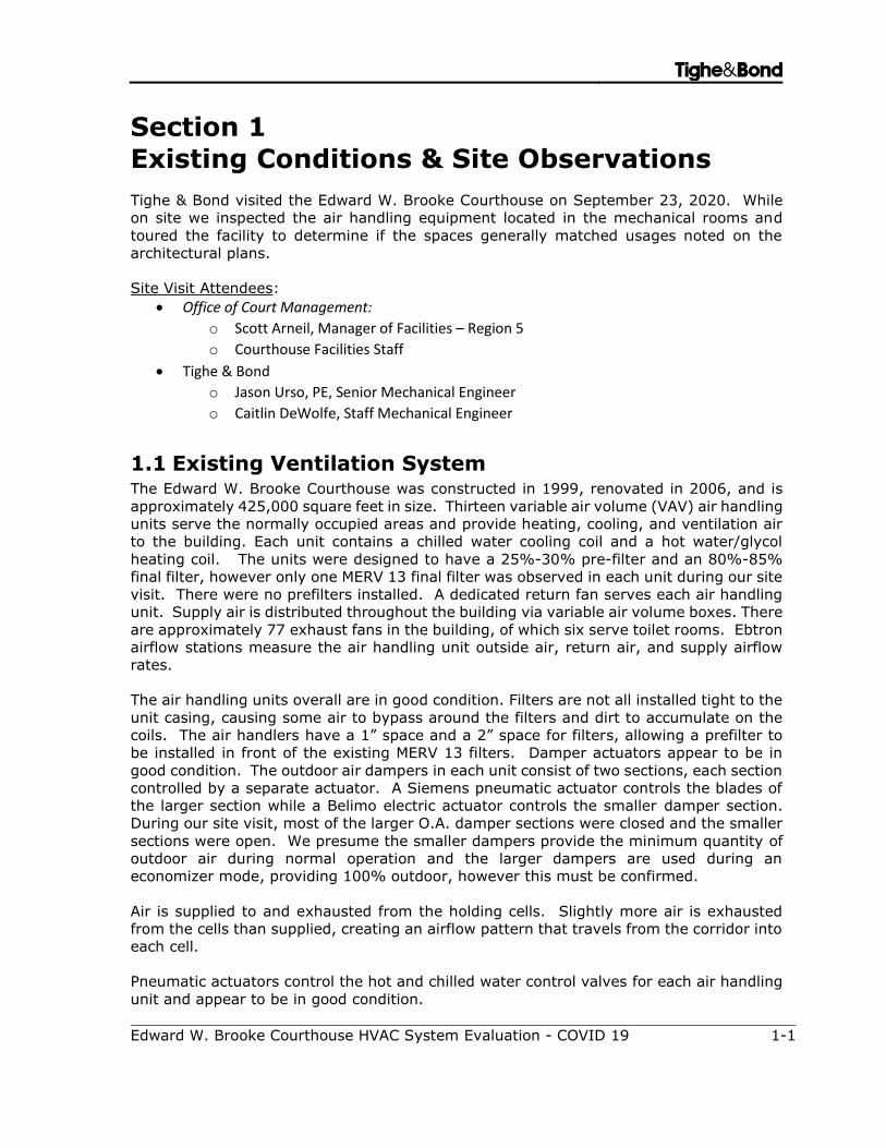
1.1 Existing Ventilation System The Edward W. Brooke Courthouse was constructed in 1999, renovated in 2006, and is
approximately 425,000 square feet in size. Thirteen variable air volume (VAV) air handling
units serve the normally occupied areas and provide heating, cooling, and ventilation air
to the building. Each unit contains a chilled water cooling coil and a hot water/glycol
heating coil. The units were designed to have a 25%-30% pre-filter and an 80%-85%
final filter, however only one MERV 13 final filter was observed in each unit during our site
visit. There were no prefilters installed. A dedicated return fan serves each air handling
unit. Supply air is distributed throughout the building via variable air volume boxes. There
are approximately 77 exhaust fans in the building, of which six serve toilet rooms. Ebtron
airflow stations measure the air handling unit outside air, return air, and supply airflow
rates.
The air handling units overall are in good condition. Filters are not all installed tight to the
unit casing, causing some air to bypass around the filters and dirt to accumulate on the
coils. The air handlers have a 1” space and a 2” space for filters, allowing a prefilter to
be installed in front of the existing MERV 13 filters. Damper actuators appear to be in
good condition. The outdoor air dampers in each unit consist of two sections, each section
controlled by a separate actuator. A Siemens pneumatic actuator controls the blades of
the larger section while a Belimo electric actuator controls the smaller damper section.
During our site visit, most of the larger O.A. damper sections were closed and the smaller
sections were open. We presume the smaller dampers provide the minimum quantity of
outdoor air during normal operation and the larger dampers are used during an
economizer mode, providing 100% outdoor, however this must be confirmed.
Air is supplied to and exhausted from the holding cells. Slightly more air is exhausted
from the cells than supplied, creating an airflow pattern that travels from the corridor into
each cell.
Pneumatic actuators control the hot and chilled water control valves for each air handling
unit and appear to be in good condition.

Section 1 Existing Conditions & Site Observations Tighe&Bond
Edward W. Brooke Courthouse HVAC System Evaluation - COVID 19 1-2
During our site visit, facilities staff indicated they have a lack of heat in the lobby area.
There are no other temperature control issues that facilities staff are aware of. We also
noticed that there are no supply air diffusers or grilles in offices B602 through B610 and
there is no supply air in the hall outside these offices. AHU-13 was not operating at the
time of our site investigations, and AHU-5 had a puddle of water around the perimeter of
the unit. It is unclear what may have caused the puddle of water. In reviewing the 2004
design drawings, it appears the zones originally supplied from AHU-13 were allocated to
AHU-4 and AHU-13 was abandoned in place.
Two 850 ton, water cooled chillers provide chilled water to the air handling units and four
8,000 MBH, gas fired steam boilers generate steam for the building.
Table 1 summarizes the air handling units’ designed airflow rates, the MERV rating of the
installed filters, and the overall condition.
TABLE 1 Existing Air Handling Units
Unit Design Airflow
(CFM)
Design Min. O.A.
(CFM)
Filter Condition
AHU-1 26,000 6,200 MERV 13 Good
AHU-2 20.500 5,000 MERV 13 Good
AHU-3 26,000 6,400 MERV 13 Good
AHU-4 27,000 6,000 MERV 13 Good
AHU-5 21,000 8,000 MERV 13 Good
AHU-6 27,400 11,000 MERV 13 Good
AHU-7 29,000 12,000 MERV 13 Good
AHU-8 32,000 7,000 MERV 13 Good
AHU-9 17,000 4,000 MERV 13 Good
AHU-10 15,000 3,600 MERV 13 Good
AHU-11 16,000 4,000 MERV 13 Good
AHU-12 6,800 3,800 MERV 13 Good
AHU-13 5,600 5,600 MERV 13 Good
Section 1 Existing Conditions & Site Observations Tighe&Bond
Edward W. Brooke Courthouse HVAC System Evaluation - COVID 19 1-3
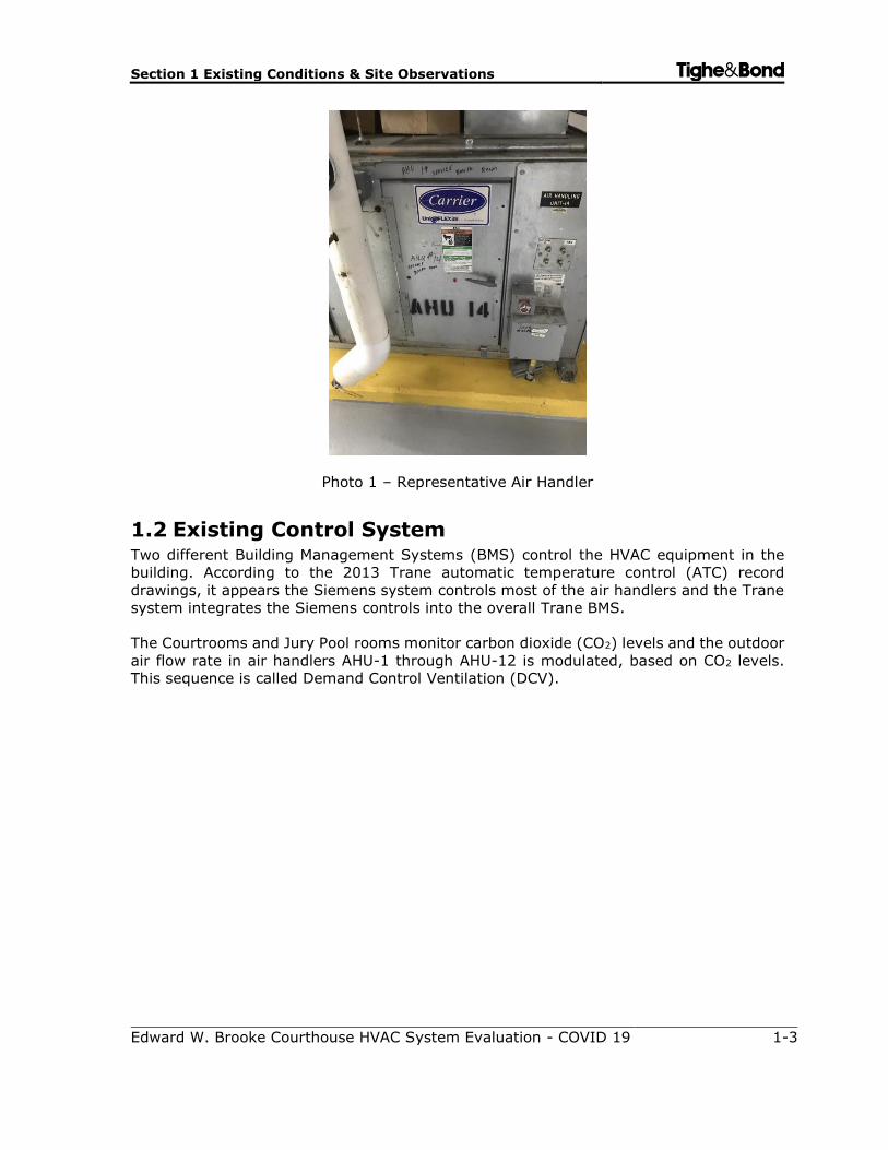
Photo 1 – Representative Air Handler
1.2 Existing Control System Two different Building Management Systems (BMS) control the HVAC equipment in the
building. According to the 2013 Trane automatic temperature control (ATC) record
drawings, it appears the Siemens system controls most of the air handlers and the Trane
system integrates the Siemens controls into the overall Trane BMS.
The Courtrooms and Jury Pool rooms monitor carbon dioxide (CO2) levels and the outdoor
air flow rate in air handlers AHU-1 through AHU-12 is modulated, based on CO2 levels.
This sequence is called Demand Control Ventilation (DCV).
Tighe&Bond
Edward W. Brooke Courthouse HVAC System Evaluation - COVID 19 2-1
Section 2
Recommendations
Below is a list of recommendations that we propose for the E.W. Brooke Courthouse.
Please refer to the “Master Recommendation List” for further explanation and
requirements of the stated recommendations.
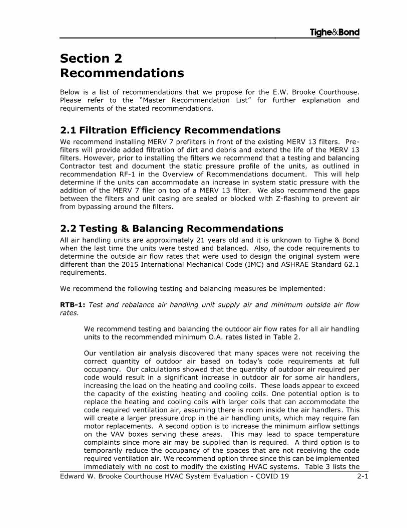
2.1 Filtration Efficiency Recommendations We recommend installing MERV 7 prefilters in front of the existing MERV 13 filters. Pre-
filters will provide added filtration of dirt and debris and extend the life of the MERV 13
filters. However, prior to installing the filters we recommend that a testing and balancing
Contractor test and document the static pressure profile of the units, as outlined in
recommendation RF-1 in the Overview of Recommendations document. This will help
determine if the units can accommodate an increase in system static pressure with the
addition of the MERV 7 filer on top of a MERV 13 filter. We also recommend the gaps
between the filters and unit casing are sealed or blocked with Z-flashing to prevent air
from bypassing around the filters.
2.2 Testing & Balancing Recommendations All air handling units are approximately 21 years old and it is unknown to Tighe & Bond
when the last time the units were tested and balanced. Also, the code requirements to
determine the outside air flow rates that were used to design the original system were
different than the 2015 International Mechanical Code (IMC) and ASHRAE Standard 62.1
requirements.
We recommend the following testing and balancing measures be implemented:
RTB-1: Test and rebalance air handling unit supply air and minimum outside air flow
rates.
We recommend testing and balancing the outdoor air flow rates for all air handling
units to the recommended minimum O.A. rates listed in Table 2.
Our ventilation air analysis discovered that many spaces were not receiving the
correct quantity of outdoor air based on today’s code requirements at full
occupancy. Our calculations showed that the quantity of outdoor air required per
code would result in a significant increase in outdoor air for some air handlers,
increasing the load on the heating and cooling coils. These loads appear to exceed
the capacity of the existing heating and cooling coils. One potential option is to
replace the heating and cooling coils with larger coils that can accommodate the
code required ventilation air, assuming there is room inside the air handlers. This
will create a larger pressure drop in the air handling units, which may require fan
motor replacements. A second option is to increase the minimum airflow settings
on the VAV boxes serving these areas. This may lead to space temperature
complaints since more air may be supplied than is required. A third option is to
temporarily reduce the occupancy of the spaces that are not receiving the code
required ventilation air. We recommend option three since this can be implemented
immediately with no cost to modify the existing HVAC systems. Table 3 lists the
Section 2 Recommendations Tighe&Bond
Edward W. Brooke Trial Courthouse HVAC System Evaluation - COVID 19 2-2
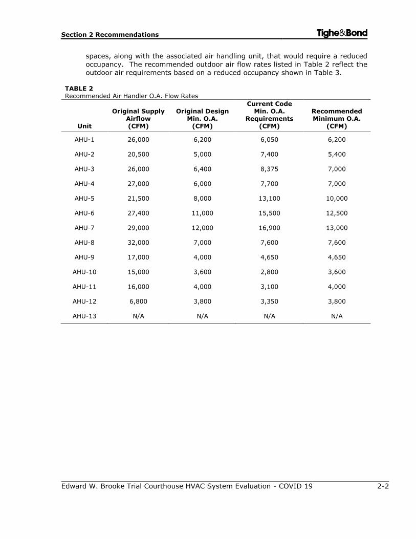
spaces, along with the associated air handling unit, that would require a reduced
occupancy. The recommended outdoor air flow rates listed in Table 2 reflect the
outdoor air requirements based on a reduced occupancy shown in Table 3.
TABLE 2 Recommended Air Handler O.A. Flow Rates
Unit
Original Supply Airflow (CFM)
Original Design Min. O.A.
(CFM)
Current Code Min. O.A.
Requirements (CFM)
Recommended Minimum O.A.
(CFM)
AHU-1 26,000 6,200 6,050 6,200
AHU-2 20,500 5,000 7,400 5,400
AHU-3 26,000 6,400 8,375 7,000
AHU-4 27,000 6,000 7,700 7,000
AHU-5 21,500 8,000 13,100 10,000
AHU-6 27,400 11,000 15,500 12,500
AHU-7 29,000 12,000 16,900 13,000
AHU-8 32,000 7,000 7,600 7,600
AHU-9 17,000 4,000 4,650 4,650
AHU-10 15,000 3,600 2,800 3,600
AHU-11 16,000 4,000 3,100 4,000
AHU-12 6,800 3,800 3,350 3,800
AHU-13 N/A N/A N/A N/A
Section 2 Recommendations Tighe&Bond
Edward W. Brooke Trial Courthouse HVAC System Evaluation - COVID 19 2-3
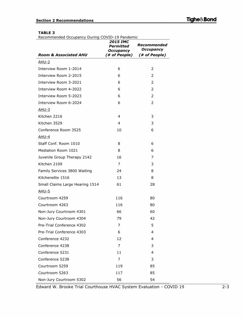
TABLE 3
Recommended Occupancy During COVID-19 Pandemic
Room & Associated AHU
2015 IMC Permitted Occupancy
(# of People)
Recommended Occupancy
(# of People)
AHU-2
Interview Room 1-2014 6 2
Interview Room 2-2015 6 2
Interview Room 3-2021 6 2
Interview Room 4-2022 6 2
Interview Room 5-2023 6 2
Interview Room 6-2024 6 2
AHU-3
Kitchen 2216 4 3
Kitchen 3529 4 3
Conference Room 3525 10 6
AHU-4
Staff Conf. Room 1010 8 6
Mediation Room 1021 8 6
Juvenile Group Therapy 2142 16 7
Kitchen 2109 7 3
Family Services 3800 Waiting 24 8
Kitchenette 1516 13 8
Small Claims Large Hearing 1514 61 28
AHU-5
Courtroom 4259 116 80
Courtroom 4263 116 80
Non-Jury Courtroom 4301 66 60
Non-Jury Courtroom 4304 79 42
Pre-Trial Conference 4302 7 5
Pre-Trial Conference 4303 6 4
Conference 4232 12 4
Conference 4238 7 3
Conference 5231 11 4
Conference 5238 7 3
Courtroom 5259 119 85
Courtroom 5263 117 85
Non-Jury Courtroom 5302 56 54
Section 2 Recommendations Tighe&Bond
Edward W. Brooke Trial Courthouse HVAC System Evaluation - COVID 19 2-4
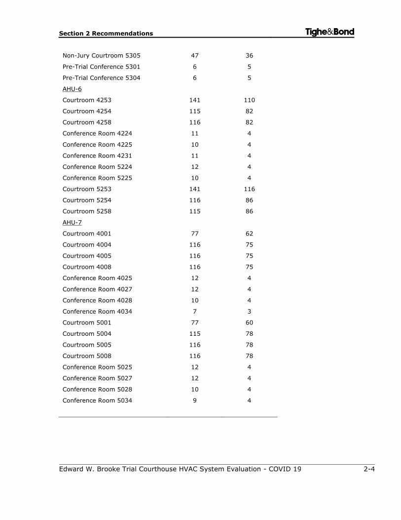
Non-Jury Courtroom 5305 47 36
Pre-Trial Conference 5301 6 5
Pre-Trial Conference 5304 6 5
AHU-6
Courtroom 4253 141 110
Courtroom 4254 115 82
Courtroom 4258 116 82
Conference Room 4224 11 4
Conference Room 4225 10 4
Conference Room 4231 11 4
Conference Room 5224 12 4
Conference Room 5225 10 4
Courtroom 5253 141 116
Courtroom 5254 116 86
Courtroom 5258 115 86
AHU-7
Courtroom 4001 77 62
Courtroom 4004 116 75
Courtroom 4005 116 75
Courtroom 4008 116 75
Conference Room 4025 12 4
Conference Room 4027 12 4
Conference Room 4028 10 4
Conference Room 4034 7 3
Courtroom 5001 77 60
Courtroom 5004 115 78
Courtroom 5005 116 78
Courtroom 5008 116 78
Conference Room 5025 12 4
Conference Room 5027 12 4
Conference Room 5028 10 4
Conference Room 5034 9 4
Section 2 Recommendations Tighe&Bond
Edward W. Brooke Trial Courthouse HVAC System Evaluation - COVID 19 2-5
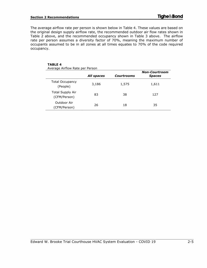
The average airflow rate per person is shown below in Table 4. These values are based on
the original design supply airflow rate, the recommended outdoor air flow rates shown in
Table 2 above, and the recommended occupancy shown in Table 3 above. The airflow
rate per person assumes a diversity factor of 70%, meaning the maximum number of
occupants assumed to be in all zones at all times equates to 70% of the code required
occupancy.
TABLE 4 Average Airflow Rate per Person
All spaces Courtrooms Non-Courtroom
Spaces
Total Occupancy
(People) 3,186 1,575 1,611
Total Supply Air
(CFM/Person) 83 38 127
Outdoor Air
(CFM/Person) 26 18 35
Section 2 Recommendations Tighe&Bond
Edward W. Brooke Trial Courthouse HVAC System Evaluation - COVID 19 2-6
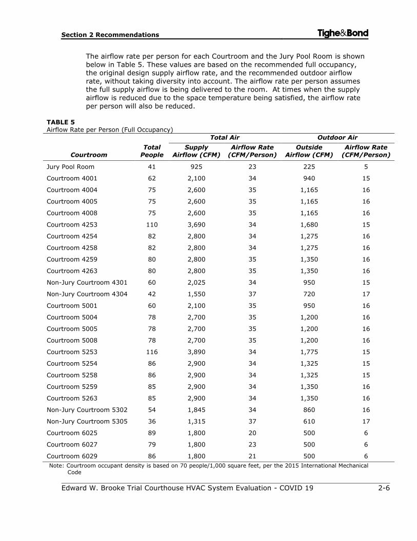
The airflow rate per person for each Courtroom and the Jury Pool Room is shown
below in Table 5. These values are based on the recommended full occupancy,
the original design supply airflow rate, and the recommended outdoor airflow
rate, without taking diversity into account. The airflow rate per person assumes
the full supply airflow is being delivered to the room. At times when the supply
airflow is reduced due to the space temperature being satisfied, the airflow rate
per person will also be reduced.
TABLE 5 Airflow Rate per Person (Full Occupancy)
Courtroom
Total
People
Total Air Outdoor Air
Supply
Airflow (CFM)
Airflow Rate
(CFM/Person)
Outside
Airflow (CFM)
Airflow Rate
(CFM/Person)
Jury Pool Room 41 925 23 225 5
Courtroom 4001 62 2,100 34 940 15
Courtroom 4004 75 2,600 35 1,165 16
Courtroom 4005 75 2,600 35 1,165 16
Courtroom 4008 75 2,600 35 1,165 16
Courtroom 4253 110 3,690 34 1,680 15
Courtroom 4254 82 2,800 34 1,275 16
Courtroom 4258 82 2,800 34 1,275 16
Courtroom 4259 80 2,800 35 1,350 16
Courtroom 4263 80 2,800 35 1,350 16
Non-Jury Courtroom 4301 60 2,025 34 950 15
Non-Jury Courtroom 4304 42 1,550 37 720 17
Courtroom 5001 60 2,100 35 950 16
Courtroom 5004 78 2,700 35 1,200 16
Courtroom 5005 78 2,700 35 1,200 16
Courtroom 5008 78 2,700 35 1,200 16
Courtroom 5253 116 3,890 34 1,775 15
Courtroom 5254 86 2,900 34 1,325 15
Courtroom 5258 86 2,900 34 1,325 15
Courtroom 5259 85 2,900 34 1,350 16
Courtroom 5263 85 2,900 34 1,350 16
Non-Jury Courtroom 5302 54 1,845 34 860 16
Non-Jury Courtroom 5305 36 1,315 37 610 17
Courtroom 6025 89 1,800 20 500 6
Courtroom 6027 79 1,800 23 500 6
Courtroom 6029 86 1,800 21 500 6
Note: Courtroom occupant density is based on 70 people/1,000 square feet, per the 2015 International Mechanical Code
Section 2 Recommendations Tighe&Bond
Edward W. Brooke Trial Courthouse HVAC System Evaluation - COVID 19 2-7
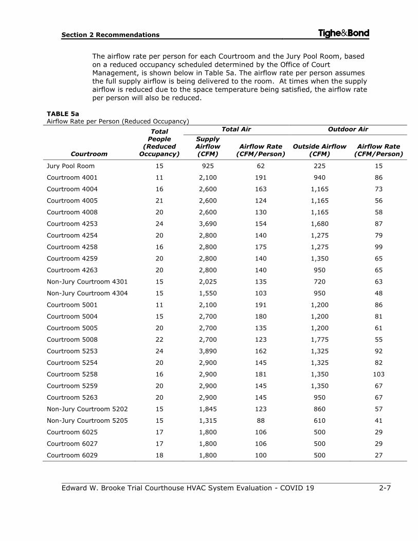
The airflow rate per person for each Courtroom and the Jury Pool Room, based
on a reduced occupancy scheduled determined by the Office of Court
Management, is shown below in Table 5a. The airflow rate per person assumes
the full supply airflow is being delivered to the room. At times when the supply
airflow is reduced due to the space temperature being satisfied, the airflow rate
per person will also be reduced.
TABLE 5a Airflow Rate per Person (Reduced Occupancy)
Courtroom
Total People
(Reduced Occupancy)
Total Air Outdoor Air
Supply Airflow (CFM)
Airflow Rate (CFM/Person)
Outside Airflow (CFM)
Airflow Rate (CFM/Person)
Jury Pool Room 15 925 62 225 15
Courtroom 4001 11 2,100 191 940 86
Courtroom 4004 16 2,600 163 1,165 73
Courtroom 4005 21 2,600 124 1,165 56
Courtroom 4008 20 2,600 130 1,165 58
Courtroom 4253 24 3,690 154 1,680 87
Courtroom 4254 20 2,800 140 1,275 79
Courtroom 4258 16 2,800 175 1,275 99
Courtroom 4259 20 2,800 140 1,350 65
Courtroom 4263 20 2,800 140 950 65
Non-Jury Courtroom 4301 15 2,025 135 720 63
Non-Jury Courtroom 4304 15 1,550 103 950 48
Courtroom 5001 11 2,100 191 1,200 86
Courtroom 5004 15 2,700 180 1,200 81
Courtroom 5005 20 2,700 135 1,200 61
Courtroom 5008 22 2,700 123 1,775 55
Courtroom 5253 24 3,890 162 1,325 92
Courtroom 5254 20 2,900 145 1,325 82
Courtroom 5258 16 2,900 181 1,350 103
Courtroom 5259 20 2,900 145 1,350 67
Courtroom 5263 20 2,900 145 950 67
Non-Jury Courtroom 5202 15 1,845 123 860 57
Non-Jury Courtroom 5205 15 1,315 88 610 41
Courtroom 6025 17 1,800 106 500 29
Courtroom 6027 17 1,800 106 500 29
Courtroom 6029 18 1,800 100 500 27
Section 2 Recommendations Tighe&Bond
Edward W. Brooke Trial Courthouse HVAC System Evaluation - COVID 19 2-8
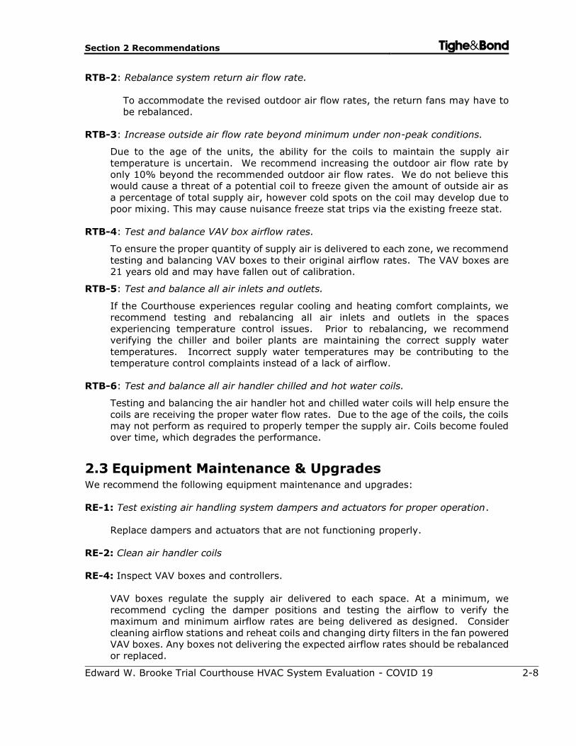
RTB-2: Rebalance system return air flow rate.
To accommodate the revised outdoor air flow rates, the return fans may have to
be rebalanced.
RTB-3: Increase outside air flow rate beyond minimum under non-peak conditions.
Due to the age of the units, the ability for the coils to maintain the supply air
temperature is uncertain. We recommend increasing the outdoor air flow rate by
only 10% beyond the recommended outdoor air flow rates. We do not believe this
would cause a threat of a potential coil to freeze given the amount of outside air as
a percentage of total supply air, however cold spots on the coil may develop due to
poor mixing. This may cause nuisance freeze stat trips via the existing freeze stat.
RTB-4: Test and balance VAV box airflow rates.
To ensure the proper quantity of supply air is delivered to each zone, we recommend
testing and balancing VAV boxes to their original airflow rates. The VAV boxes are
21 years old and may have fallen out of calibration.
RTB-5: Test and balance all air inlets and outlets.
If the Courthouse experiences regular cooling and heating comfort complaints, we
recommend testing and rebalancing all air inlets and outlets in the spaces
experiencing temperature control issues. Prior to rebalancing, we recommend
verifying the chiller and boiler plants are maintaining the correct supply water
temperatures. Incorrect supply water temperatures may be contributing to the
temperature control complaints instead of a lack of airflow.
RTB-6: Test and balance all air handler chilled and hot water coils.
Testing and balancing the air handler hot and chilled water coils will help ensure the
coils are receiving the proper water flow rates. Due to the age of the coils, the coils
may not perform as required to properly temper the supply air. Coils become fouled
over time, which degrades the performance.
2.3 Equipment Maintenance & Upgrades We recommend the following equipment maintenance and upgrades:
RE-1: Test existing air handling system dampers and actuators for proper operation.
Replace dampers and actuators that are not functioning properly.
RE-2: Clean air handler coils
RE-4: Inspect VAV boxes and controllers.
VAV boxes regulate the supply air delivered to each space. At a minimum, we
recommend cycling the damper positions and testing the airflow to verify the
maximum and minimum airflow rates are being delivered as designed. Consider
cleaning airflow stations and reheat coils and changing dirty filters in the fan powered
VAV boxes. Any boxes not delivering the expected airflow rates should be rebalanced
or replaced.
Section 2 Recommendations Tighe&Bond
Edward W. Brooke Trial Courthouse HVAC System Evaluation - COVID 19 2-9
RE-7: Test the existing air handler control valves and actuators for proper operation.
2.4 Control System We recommend the following control system modifications:
RC-1: Implement a pre and post-occupancy flush sequence.
RC-3: Install controls required to introduce outside air beyond the minimum requirements
in a stepped approach.
The existing BMS appears to be sophisticated enough to implement this type of
sequence. Prior to implementing this control strategy, the TAB Contractor should
verify the quantity of outside air the outdoor air louvers can accommodate without
exceeding an intake air velocity of 450 feet/minute (FPM). Exceeding this air velocity
through in intake air louver may result in rain or snow entering the louver.
RC-4: Confirm economizer control sequence is operational.
According to the 2013 Trane Automatic Temperature Controls (ATC) record
document, AHU-1 through AHU-12 operate with an economizer sequence. An
economizer sequence allows 100% outdoor air to be supplied to rooms while
exhausting 100% of the return air. We recommend testing to ensure this sequence
is working correctly to maximize the quantity of outdoor air when outdoor
temperature conditions allow.
RC-5: Disable demand control ventilation sequences.
Disabling demand control ventilation sequences will result in the air handling units
supplying the code required quantity of outdoor air at all times. The DCV sequence
may otherwise reduce outdoor air based on a low concentration of CO2, indicating a
period of relatively low occupancy.
We also recommend calibrating the airflow stations to ensure they are providing the
correct airflow readings.
2.5 Additional Filtration and Air Cleaning We recommend the installation of the following air cleaning devices:
RFC-1: Install portable HEPA filters.
If the Courthouse is to operate at a high capacity (i.e. 50% occupancy or greater),
we recommend installing portable HEPA filters in high traffic areas, such as entrance
lobbies. They should also be considered for Courtrooms, depending on the
occupancy of the room and how much noise is generated from the filters. The noise
levels will vary depending on the manufacturer.
Section 2 Recommendations Tighe&Bond
Edward W. Brooke Trial Courthouse HVAC System Evaluation - COVID 19 2-10
2.6 Humidity Control Installing duct mounted or portable humidifiers can help maintain the relative humidity
levels recommended by ASHRAE. The feasibility of adding active humidification is
determined by the building envelope. Buildings that were not designed to operate with
active humidification can potentially be damaged due to a lack of a vapor barrier, adequate
insulation, and air tightness.
Duct mounted humidifiers must be engineered, integrated into the building control
system, tested, and commissioned. They are available in many configurations but require
substantial maintenance and additional controls. They also run the risk of adversely
affecting IAQ from growing microorganisms, or leaking water through poorly sealed
ductwork damaging insulation and ceilings. Portable humidifiers are easier to install and
require less maintenance, but still have the potential to damage the building envelope.
While active humidification is not recommended as a whole building solution due to high
installation costs, operational costs, potential to damage the building envelope and
adversely affect poor IAQ, it may be warranted as a temporary solution in some areas.
2.7 Other Recommendations
2.7.1 Provide Ventilation Air To Offices B602 – B610.
During our visit, we observed that there were no supply diffusers or grilles in offices B602
through B610 in the basement. We recommend adding ventilation air into these spaces
by connecting into the existing ductwork distribution system in the basement. Further
field investigation and design is required.
Tighe&Bond
Edward W. Brooke Trial Courthouse HVAC System Evaluation - COVID 19 3-1
Section 3
Testing & Balancing Results
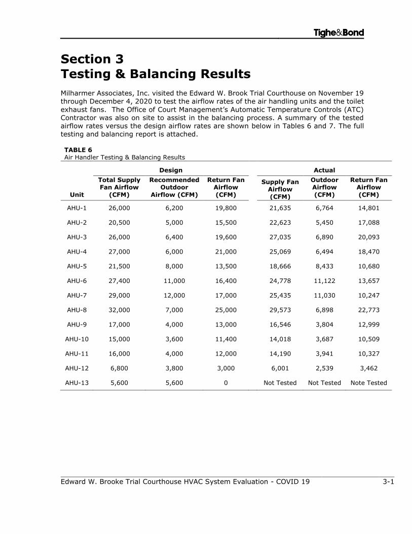
Milharmer Associates, Inc. visited the Edward W. Brook Trial Courthouse on November 19
through December 4, 2020 to test the airflow rates of the air handling units and the toilet
exhaust fans. The Office of Court Management’s Automatic Temperature Controls (ATC)
Contractor was also on site to assist in the balancing process. A summary of the tested
airflow rates versus the design airflow rates are shown below in Tables 6 and 7. The full
testing and balancing report is attached.
TABLE 6 Air Handler Testing & Balancing Results
Unit
Design
Actual
Total Supply Fan Airflow
(CFM)
Recommended Outdoor
Airflow (CFM)
Return Fan Airflow
(CFM)
Supply Fan Airflow
(CFM)
Outdoor Airflow
(CFM)
Return Fan Airflow
(CFM)
AHU-1 26,000 6,200 19,800 21,635 6,764 14,801
AHU-2 20,500 5,000 15,500 22,623 5,450 17,088
AHU-3 26,000 6,400 19,600 27,035 6,890 20,093
AHU-4 27,000 6,000 21,000 25,069 6,494 18,470
AHU-5 21,500 8,000 13,500 18,666 8,433 10,680
AHU-6 27,400 11,000 16,400 24,778 11,122 13,657
AHU-7 29,000 12,000 17,000 25,435 11,030 10,247
AHU-8 32,000 7,000 25,000 29,573 6,898 22,773
AHU-9 17,000 4,000 13,000 16,546 3,804 12,999
AHU-10 15,000 3,600 11,400 14,018 3,687 10,509
AHU-11 16,000 4,000 12,000 14,190 3,941 10,327
AHU-12 6,800 3,800 3,000 6,001 2,539 3,462
AHU-13 5,600 5,600 0 Not Tested Not Tested Note Tested
Section 3 Testing & Balancing Results Tighe&Bond
Edward W. Brooke Trial Courthouse HVAC System Evaluation - COVID 19 3-2
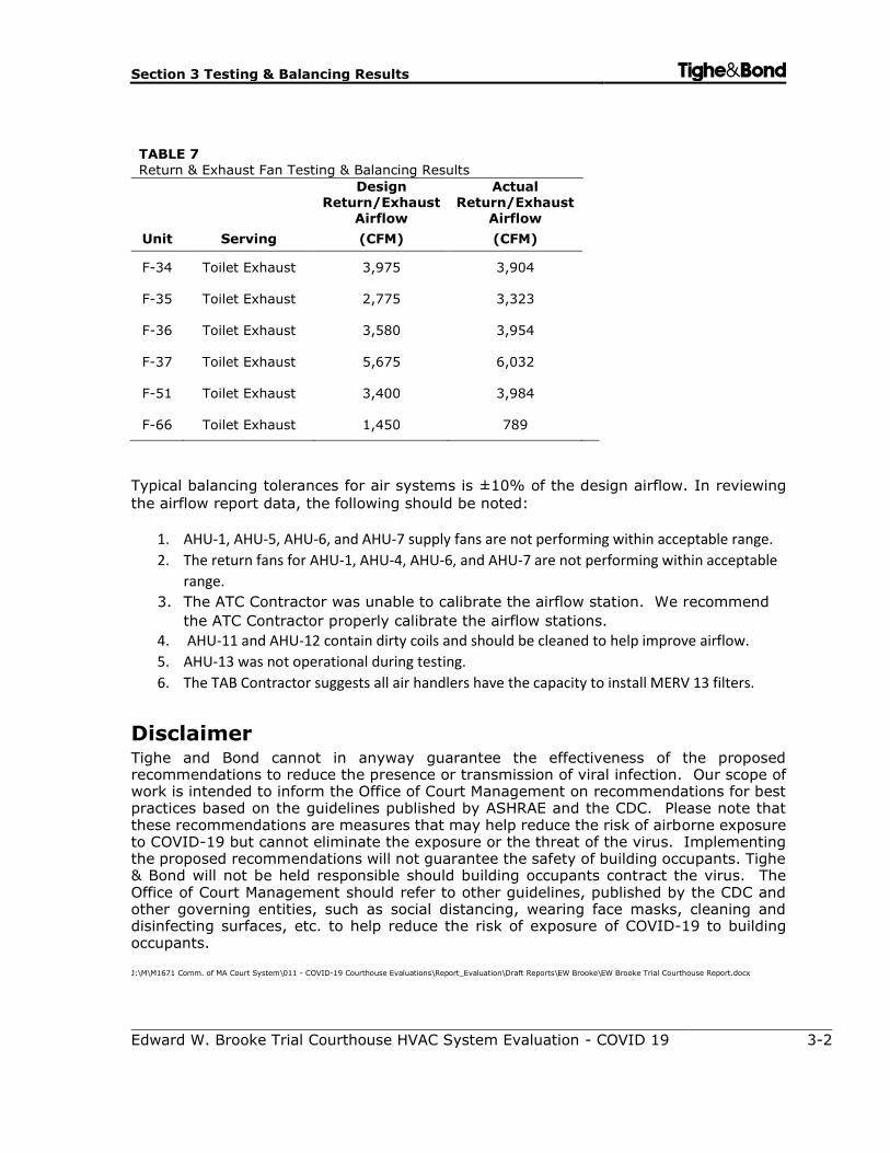
TABLE 7 Return & Exhaust Fan Testing & Balancing Results
Unit Serving
Design Return/Exhaust
Airflow
(CFM)
Actual Return/Exhaust
Airflow
(CFM)
F-34 Toilet Exhaust 3,975 3,904
F-35 Toilet Exhaust 2,775 3,323
F-36 Toilet Exhaust 3,580 3,954
F-37 Toilet Exhaust 5,675 6,032
F-51 Toilet Exhaust 3,400 3,984
F-66 Toilet Exhaust 1,450 789
Typical balancing tolerances for air systems is ±10% of the design airflow. In reviewing
the airflow report data, the following should be noted:
1. AHU-1, AHU-5, AHU-6, and AHU-7 supply fans are not performing within acceptable range.
2. The return fans for AHU-1, AHU-4, AHU-6, and AHU-7 are not performing within acceptable
range.
3. The ATC Contractor was unable to calibrate the airflow station. We recommend
the ATC Contractor properly calibrate the airflow stations.
4. AHU-11 and AHU-12 contain dirty coils and should be cleaned to help improve airflow.
5. AHU-13 was not operational during testing.
6. The TAB Contractor suggests all air handlers have the capacity to install MERV 13 filters.
Disclaimer Tighe and Bond cannot in anyway guarantee the effectiveness of the proposed recommendations to reduce the presence or transmission of viral infection. Our scope of work is intended to inform the Office of Court Management on recommendations for best practices based on the guidelines published by ASHRAE and the CDC. Please note that these recommendations are measures that may help reduce the risk of airborne exposure to COVID-19 but cannot eliminate the exposure or the threat of the virus. Implementing the proposed recommendations will not guarantee the safety of building occupants. Tighe & Bond will not be held responsible should building occupants contract the virus. The Office of Court Management should refer to other guidelines, published by the CDC and other governing entities, such as social distancing, wearing face masks, cleaning and disinfecting surfaces, etc. to help reduce the risk of exposure of COVID-19 to building occupants.
J:\M\M1671 Comm. of MA Court System\011 - COVID-19 Courthouse Evaluations\Report_Evaluation\Draft Reports\EW Brooke\EW Brooke Trial Courthouse Report.docx
MILHARMER ASSOCIATES, INC.
Project:
Project No.: 20-551 Project Date:
MECHANICAL CONTRACTOR
3384
A N.E.B.B. Certified Company
534 New State Highway, Route 44, Suite 3
Raynham, MA 02767
Tel.: 508-823-8500; Facsimile: 508-823-8600
TEST AND BALANCE REPORT
12/2/2020
Edward W Brooke Courthouse
Tighe & Bond
24 New Chardon St., Boston, MA
Page 1 Milharmer Associates, Inc.
Project:
Address:
Date: Project No.
Certification No.: 3384 Certification Expiration Date: 3-31-21
The data presented in this Report is a record of system measurements and final adjustments that
have been obtained in accordance with the current edition of the N.E.B.B. Procedural Standards for
Testing, Adjusting and Balancing of Environmental Systems. Any variances from design quantities which
exceed N.E.B.B. tolerances, are noted in the Test-Adjust-Balance Report Project Summary.
N.E.B.B. Qualified TAB Supervisor Signature:_________________________________________
N.E.B.B. Qualified TAB Supervisor Name: Scott F. Miller
Submitted & Certified by:
Milharmer Associates, Inc.
Edward W Brooke Courthouse
24 New Chardon St., Boston, MA
12/2/2020 20-551
CERTIFICATION
Page 2 Milharmer Associates, Inc.
Page 3 Milharmer Associates, Inc.
Page 4 Milharmer Associates, Inc.
Project:
Address:
Date: 12/2/2020 Project No.
TABLE OF CONTENTS
SECTION 1
SECTION 2 TAB Building Systems
Edward W Brooke Courthouse
24 New Chardon St., Boston, MA
20-551
TAB Qualifications
E. Symbol Sheet
A. N.E.B.B. Certification
B. N.E.B.B. Company Certificate
C. N.E.B.B. Supervisor Certificate
D. Instrument Sheet
Page 5 Milharmer Associates, Inc.
Project:
Address:
Date: Project No.
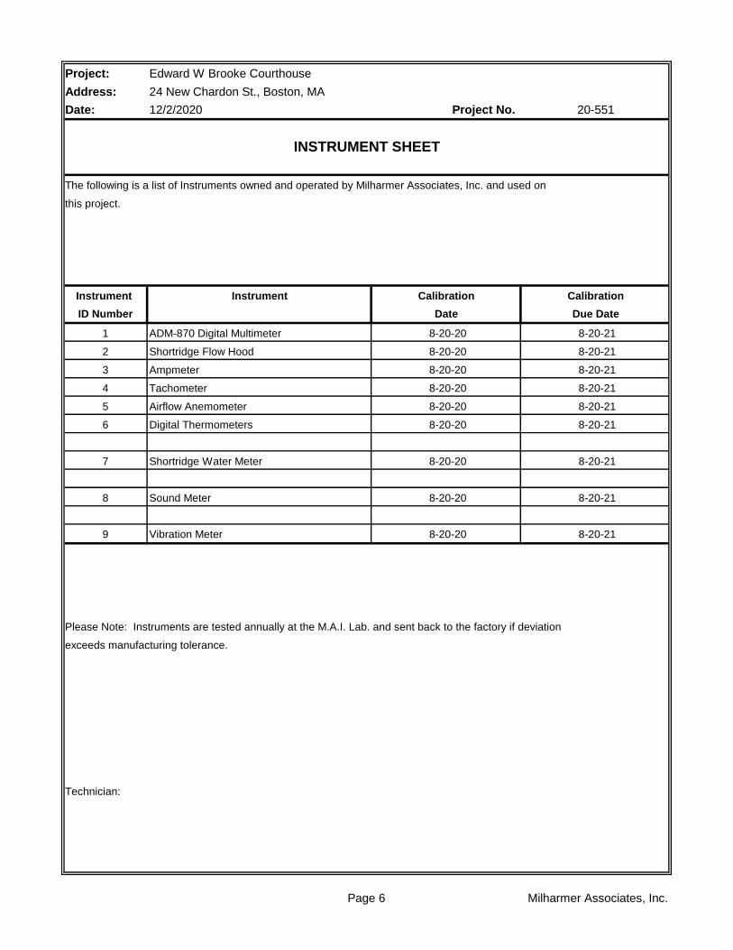
The following is a list of Instruments owned and operated by Milharmer Associates, Inc. and used on
this project.
Instrument
ID Number
1
2
3
4
5
6
7 Shortridge Water Meter
8 Sound Meter
9 Vibration Meter
Please Note: Instruments are tested annually at the M.A.I. Lab. and sent back to the factory if deviation
exceeds manufacturing tolerance.
Technician:
Edward W Brooke Courthouse
24 New Chardon St., Boston, MA
12/2/2020 20-551
INSTRUMENT SHEET
Instrument Calibration Calibration
Date Due Date
ADM-870 Digital Multimeter 8-20-20 8-20-21
Shortridge Flow Hood 8-20-20 8-20-21
Ampmeter 8-20-20 8-20-21
Tachometer 8-20-20 8-20-21
Airflow Anemometer 8-20-20 8-20-21
8-20-20 8-20-21
Digital Thermometers 8-20-20 8-20-21
8-20-20 8-20-21
8-20-20 8-20-21
Page 6 Milharmer Associates, Inc.
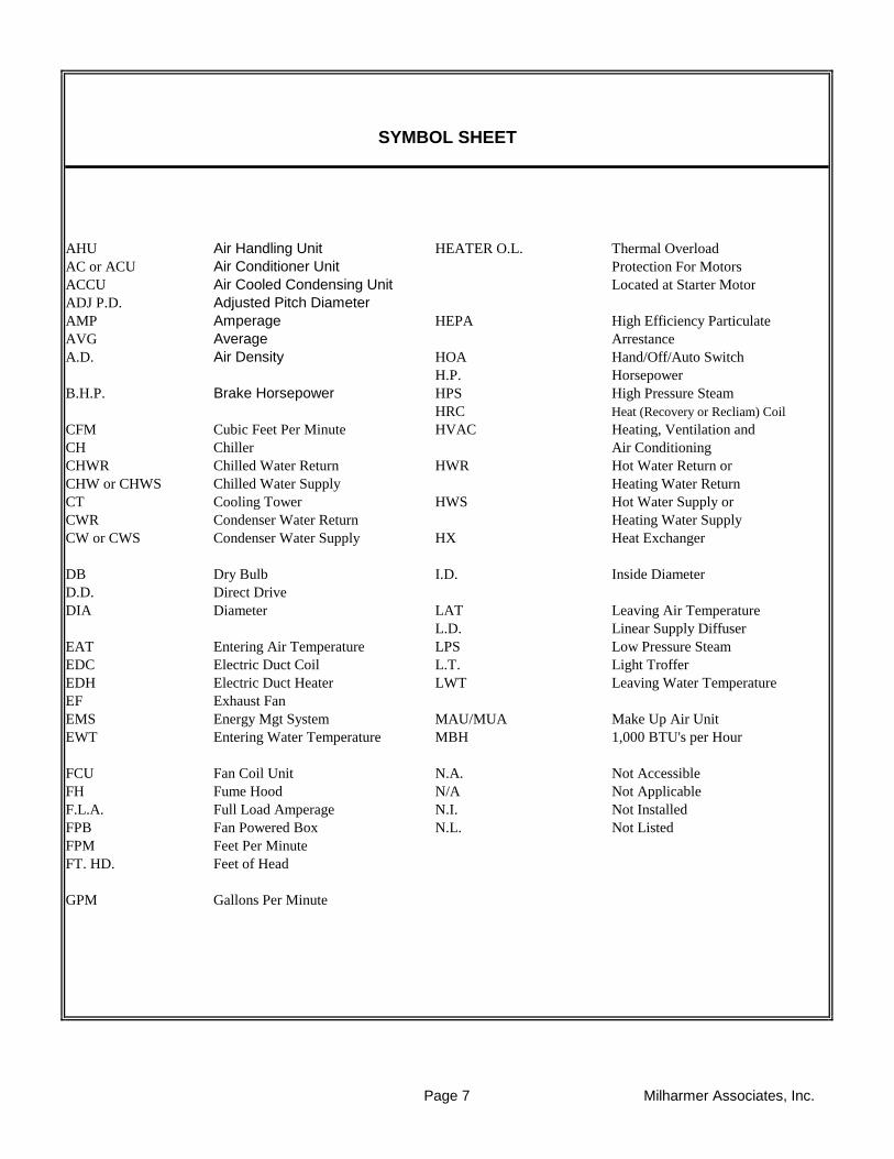
AHU Air Handling Unit HEATER O.L. Thermal Overload
AC or ACU Air Conditioner Unit Protection For Motors
ACCU Air Cooled Condensing Unit Located at Starter Motor
ADJ P.D. Adjusted Pitch Diameter
AMP Amperage HEPA High Efficiency Particulate
AVG Average Arrestance
A.D. Air Density HOA Hand/Off/Auto Switch
H.P. Horsepower
B.H.P. Brake Horsepower HPS High Pressure Steam
HRC Heat (Recovery or Recliam) Coil
CFM Cubic Feet Per Minute HVAC Heating, Ventilation and
CH Chiller Air Conditioning
CHWR Chilled Water Return HWR Hot Water Return or
CHW or CHWS Chilled Water Supply Heating Water Return
CT Cooling Tower HWS Hot Water Supply or
CWR Condenser Water Return Heating Water Supply
CW or CWS Condenser Water Supply HX Heat Exchanger
DB Dry Bulb I.D. Inside Diameter
D.D. Direct Drive
DIA Diameter LAT Leaving Air Temperature
L.D. Linear Supply Diffuser
EAT Entering Air Temperature LPS Low Pressure Steam
EDC Electric Duct Coil L.T. Light Troffer
EDH Electric Duct Heater LWT Leaving Water Temperature
EF Exhaust Fan
EMS Energy Mgt System MAU/MUA Make Up Air Unit
EWT Entering Water Temperature MBH 1,000 BTU's per Hour
FCU Fan Coil Unit N.A. Not Accessible
FH Fume Hood N/A Not Applicable
F.L.A. Full Load Amperage N.I. Not Installed
FPB Fan Powered Box N.L. Not Listed
FPM Feet Per Minute
FT. HD. Feet of Head
GPM Gallons Per Minute
SYMBOL SHEET
Page 7 Milharmer Associates, Inc.
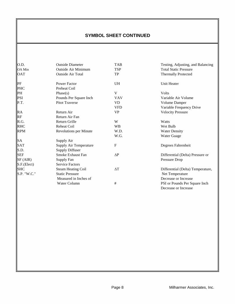
O.D. Outside Diameter TAB Testing, Adjusting, and Balancing
OA Min Outside Air Minimum TSP Total Static Pressure
OAT Outside Air Total TP Thermally Protected
PF Power Factor UH Unit Heater
PHC Preheat Coil
PH Phase(s) V Volts
PSI Pounds Per Square Inch VAV Variable Air Volume
P.T. Pitot Traverse VD Volume Damper
VFD Variable Frequency Drive
RA Return Air VP Velocity Pressure
RF Return Air Fan
R.G. Return Grille W Watts
RHC Reheat Coil WB Wet Bulb
RPM Revolutions per Minute W.D. Water Density
W.G. Water Guage
SA Supply Air
SAT Supply Air Temperature F Degrees Fahrenheit
S.D. Supply Diffuser
SEF Smoke Exhaust Fan ΔP Differential (Delta) Pressure or
SF (AIR) Supply Fan Pressure Drop
S.F.(Elect) Service Factors
SHC Steam Heating Coil ΔT Differential (Delta) Temperature,
S.P. "W.C." Static Pressure Net Temperature
Measured in Inches of Decrease or Increase
Water Column # PSI or Pounds Per Square Inch
Decrease or Increase
SYMBOL SHEET CONTINUED
Page 8 Milharmer Associates, Inc.
Project:
Address:
Date: Project No.
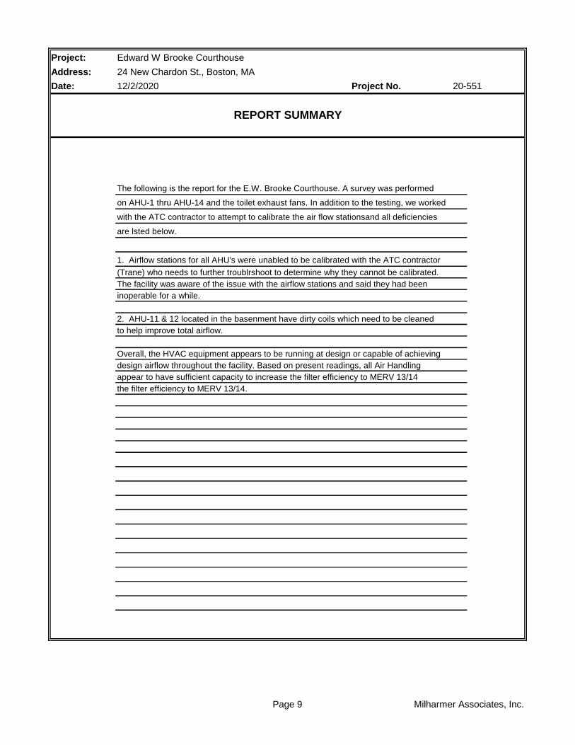
The following is the report for the E.W. Brooke Courthouse. A survey was performed
on AHU-1 thru AHU-14 and the toilet exhaust fans. In addition to the testing, we worked
with the ATC contractor to attempt to calibrate the air flow stationsand all deficiencies
are lsted below.
1. Airflow stations for all AHU's were unabled to be calibrated with the ATC contractor
(Trane) who needs to further troublrshoot to determine why they cannot be calibrated.
The facility was aware of the issue with the airflow stations and said they had been
inoperable for a while.
2. AHU-11 & 12 located in the basenment have dirty coils which need to be cleaned
to help improve total airflow.
Overall, the HVAC equipment appears to be running at design or capable of achieving
design airflow throughout the facility. Based on present readings, all Air Handling
appear to have sufficient capacity to increase the filter efficiency to MERV 13/14
the filter efficiency to MERV 13/14.
Edward W Brooke Courthouse
24 New Chardon St., Boston, MA
12/2/2020 20-551
REPORT SUMMARY
Page 9 Milharmer Associates, Inc.
Project:
Address:
Date: Project No.
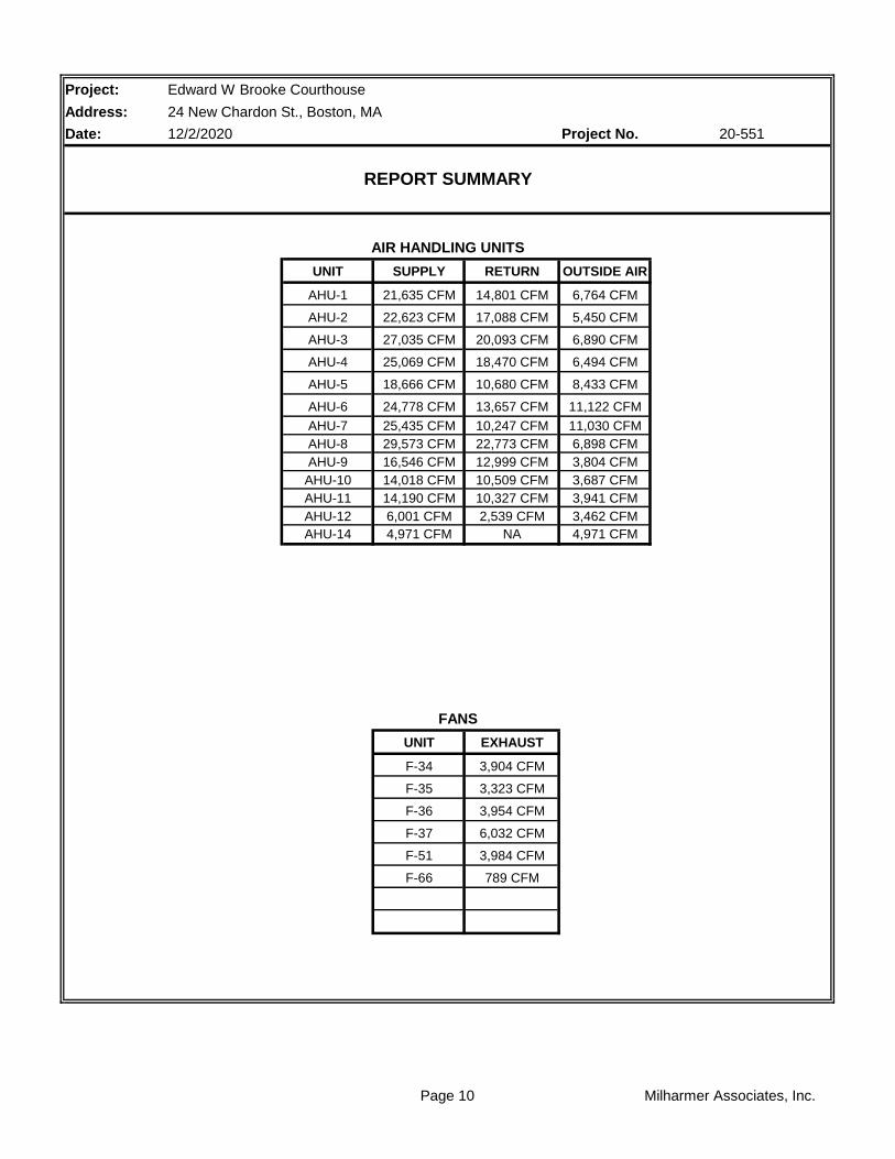
UNIT SUPPLY RETURN OUTSIDE AIR
AHU-1 21,635 CFM 14,801 CFM 6,764 CFM
AHU-2 22,623 CFM 17,088 CFM 5,450 CFM
AHU-3 27,035 CFM 20,093 CFM 6,890 CFM
AHU-4 25,069 CFM 18,470 CFM 6,494 CFM
AHU-5 18,666 CFM 10,680 CFM 8,433 CFM
AHU-6 24,778 CFM 13,657 CFM 11,122 CFM
AHU-7 25,435 CFM 10,247 CFM 11,030 CFM
AHU-8 29,573 CFM 22,773 CFM 6,898 CFM
AHU-9 16,546 CFM 12,999 CFM 3,804 CFM
AHU-10 14,018 CFM 10,509 CFM 3,687 CFM
AHU-11 14,190 CFM 10,327 CFM 3,941 CFM
AHU-12 6,001 CFM 2,539 CFM 3,462 CFM
AHU-14 4,971 CFM NA 4,971 CFM
UNIT EXHAUST
F-34 3,904 CFM
F-35 3,323 CFM
F-36 3,954 CFM
F-37 6,032 CFM
F-51 3,984 CFM
F-66 789 CFM
AIR HANDLING UNITS
FANS
Edward W Brooke Courthouse
24 New Chardon St., Boston, MA
12/2/2020 20-551
REPORT SUMMARY
Page 10 Milharmer Associates, Inc.
Project: Edward W Brooke Courthouse
Address: 24 New Chardon St., Boston, MA
Date: 12/2/2020 Project No.
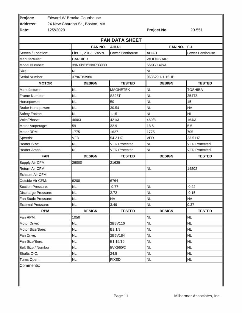
AHU-1 F-1
Lower Penthouse Lower Penthouse
TESTED TESTED
MAGNETEK TOSHIBA
S326T 254TZ
50 15
30.54 NA
1.15 NL
421/3 164/3
32.9 5.5
1627 705
54.2 HZ 23.5 HZ
VFD Protected VFD Protected
VFD Protected VFD Protected
TESTED TESTED
21635
14802
6764
-0.77 -0.22
2.72 -0.15
NA NA
3.49 0.37
TESTED TESTED
NL
2B5V110 NL
B2 1/8 NL
2B5V184 NL
B1 15/16 NL
5VX960/2 NL
24.5 NL
FIXED NL
Comments:
20-551
FAN DATA SHEET
Serves / Location:
FAN NO. FAN NO.
Manufacturer: CARRIER WOODS AIR
Flrs. 1, 2 & 3 VAV's AHU-1
Model Number: 39NXB615NVR83980 66KG 14P/A
Size: NL NL
Serial Number: 3796T83980 963629H-1 15HP
MOTOR DESIGN DESIGN
Manufacturer: NL NL
Frame Number: NL NL
Horsepower: NL NL
Brake Horsepower: NL NL
Safety Factor: NL NL
Volts/Phase: 460/3 460/3
Motor Amperage: 59 18.5
Motor RPM: 1775 1775
Speeds: VFD VFD
Heater Size: NL NL
Heater Amps.: NL NL
FAN DESIGN DESIGN
Supply Air CFM: 26000
Return Air CFM: NL
Exhaust Air CFM:
Outside Air CFM: 6200
Suction Pressure: NL NL
Discharge Pressure: NL NL
Fan Static Pressure: NL NL
External Pressure: NL NL
RPM DESIGN DESIGN
Fan RPM: 1050 NL
Motor Drive: NL NL
Motor Size/Bore: NL NL
Fan Drive: NL NL
Turns Open: NL NL
Fan Size/Bore: NL NL
Belt Size / Number: NL NL
Shafts C-C: NL NL
Page 11 Milharmer Associates, Inc.

Page 12 Milharmer Associates, Inc.

Project:
Address:
Date: Project No.
RA
HWC CHW
OA 1 2 3 4 5
FILTER
LOCATION STATIC
1 -0.45"
2 -0.57"
3 -0.77"
4 +2.72"
5 +2.05"
** Pressures measured wiith VAV Boxes at full cooling position.
Edward W Brooke Courthouse
24 New Chardon St., Boston, MA
12/2/2020 20-551
AHU-1 STATIC PROFILE
Page 13 Milharmer Associates, Inc.
Project:
Address:
Date: Project No.
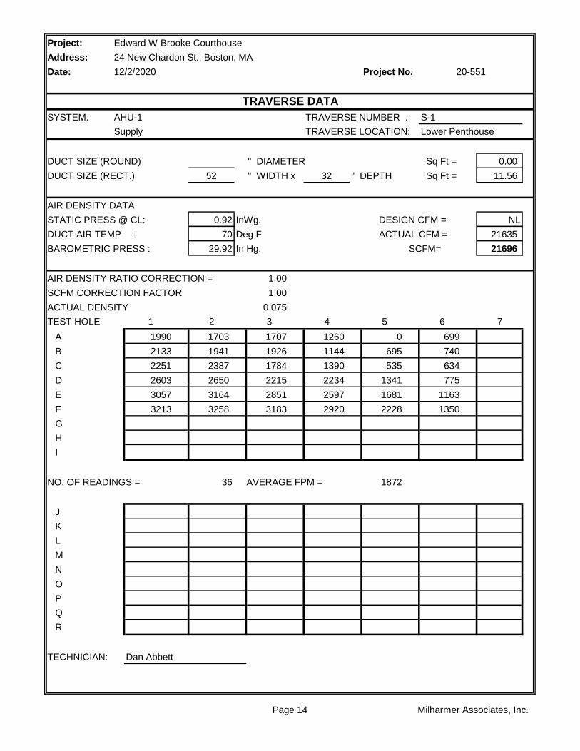
SYSTEM: AHU-1 TRAVERSE NUMBER : S-1
Supply TRAVERSE LOCATION: Lower Penthouse
DUCT SIZE (ROUND) " DIAMETER Sq Ft = 0.00
DUCT SIZE (RECT.) 52 " WIDTH x 32 " DEPTH Sq Ft = 11.56
AIR DENSITY DATA
STATIC PRESS @ CL: 0.92 InWg. DESIGN CFM = NL
DUCT AIR TEMP : 70 Deg F ACTUAL CFM = 21635
BAROMETRIC PRESS : 29.92 In Hg. SCFM= 21696
AIR DENSITY RATIO CORRECTION = 1.00
SCFM CORRECTION FACTOR 1.00
ACTUAL DENSITY 0.075
TEST HOLE 1 2 3 4 5 6 7
A 1990 1703 1707 1260 0 699
B 2133 1941 1926 1144 695 740
C 2251 2387 1784 1390 535 634
D 2603 2650 2215 2234 1341 775
E 3057 3164 2851 2597 1681 1163
F 3213 3258 3183 2920 2228 1350
G
H
I
NO. OF READINGS = 36 AVERAGE FPM = 1872
J
K
L
M
N
O
P
Q
R
TECHNICIAN: Dan Abbett
TRAVERSE DATA
Edward W Brooke Courthouse
24 New Chardon St., Boston, MA
12/2/2020 20-551
Page 14 Milharmer Associates, Inc.
Project:
Address:
Date: Project No.
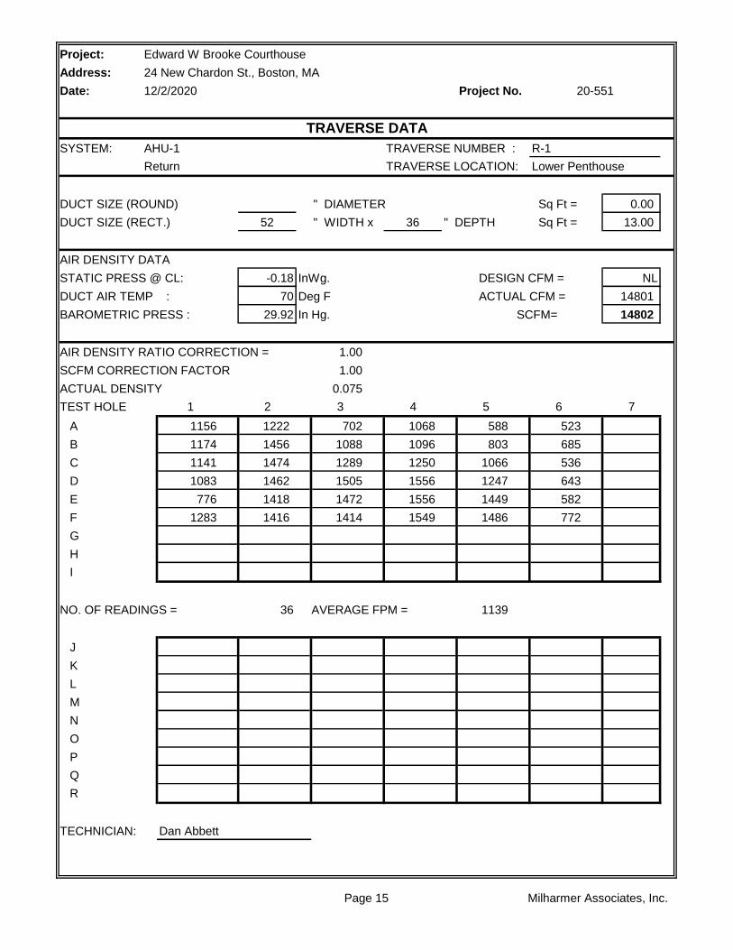
SYSTEM: AHU-1 TRAVERSE NUMBER : R-1
Return TRAVERSE LOCATION: Lower Penthouse
DUCT SIZE (ROUND) " DIAMETER Sq Ft = 0.00
DUCT SIZE (RECT.) 52 " WIDTH x 36 " DEPTH Sq Ft = 13.00
AIR DENSITY DATA
STATIC PRESS @ CL: -0.18 InWg. DESIGN CFM = NL
DUCT AIR TEMP : 70 Deg F ACTUAL CFM = 14801
BAROMETRIC PRESS : 29.92 In Hg. SCFM= 14802
AIR DENSITY RATIO CORRECTION = 1.00
SCFM CORRECTION FACTOR 1.00
ACTUAL DENSITY 0.075
TEST HOLE 1 2 3 4 5 6 7
A 1156 1222 702 1068 588 523
B 1174 1456 1088 1096 803 685
C 1141 1474 1289 1250 1066 536
D 1083 1462 1505 1556 1247 643
E 776 1418 1472 1556 1449 582
F 1283 1416 1414 1549 1486 772
G
H
I
NO. OF READINGS = 36 AVERAGE FPM = 1139
J
K
L
M
N
O
P
Q
R
TECHNICIAN: Dan Abbett
Edward W Brooke Courthouse
24 New Chardon St., Boston, MA
12/2/2020 20-551
TRAVERSE DATA
Page 15 Milharmer Associates, Inc.

Project:
Address:
Date: Project No.
SYSTEM: AHU-1 TRAVERSE NUMBER : OA-1
O.A. TRAVERSE LOCATION: Lower Penthouse
DUCT SIZE (ROUND) " DIAMETER Sq Ft = 0.00
DUCT SIZE (RECT.) 34 " WIDTH x 76 " DEPTH Sq Ft = 17.94
AIR DENSITY DATA
STATIC PRESS @ CL: NA InWg. DESIGN CFM = NL
DUCT AIR TEMP : 70 Deg F ACTUAL CFM = 6764
BAROMETRIC PRESS : 29.92 In Hg. SCFM= 6768
AIR DENSITY RATIO CORRECTION = 1.00
SCFM CORRECTION FACTOR 1.00
ACTUAL DENSITY 0.075
TEST HOLE 1 2 3 4 5 6 7
A 272 460
B 386 314
C 375 304
D 369 482
E 391 416
F
G
H
I
NO. OF READINGS = 10 AVERAGE FPM = 377
J
K
L
M
N
O
P
Q
R
TECHNICIAN: Dan Abbett
Edward W Brooke Courthouse
24 New Chardon St., Boston, MA
12/2/2020 20-551
TRAVERSE DATA
Page 16 Milharmer Associates, Inc.

Project: Edward W Brooke Courthouse
Address: 24 New Chardon St., Boston, MA
Date: 12/2/2020 Project No.
AHU-2 F-2
Lower Penthouse Lower Penthouse
TESTED TESTED
MAGNETEK TOSHIBA
S324T 215TZ
40 10
23.17 NA
1.15 NL
382/3 165/3
27.5 3.8
1489 707
49.6 HZ 43.5 HZ
VFD Protected VFD Protected
VFD Protected VFD Protected
TESTED TESTED
22623
17088
5450
-0.98 -0.25
2.97 -0.18
NA NA
3.95 0.43
TESTED TESTED
NL
2B5V90 NL
B2 1/8 NL
2B5V136 NL
B1 15/16 NL
5VX780/2 NL
21" NL
FIXED NL
Comments:
20-551
FAN DATA SHEET
FAN NO. FAN NO.
Model Number: 39NXB495NBR83970 36J1/2 13P/A
Size: NL NL
Serves / Location: Flrs. 1, 2 & 3 AHU-2
Manufacturer: CARRIER WOODS AIR
Manufacturer: NL NL
Frame Number: NL NL
Serial Number: 3695T83970 963630H-10HP
MOTOR DESIGN DESIGN
Safety Factor: NL NL
Volts/Phase: 460/3 460/3
Horsepower: NL NL
Brake Horsepower: NL NL
Speeds: VFD VFD
Heater Size: NL NL
Motor Amperage: 48 12
Motor RPM: 1775 1745
Supply Air CFM: 20500
Return Air CFM: NL
Heater Amps.: NL NL
FAN DESIGN DESIGN
Suction Pressure: NL NL
Discharge Pressure: NL NL
Exhaust Air CFM:
Outside Air CFM: 5000
RPM DESIGN DESIGN
Fan RPM: 1162 NL
Fan Static Pressure: NL NL
External Pressure: NL NL
Fan Drive: NL NL
Fan Size/Bore: NL NL
Motor Drive: NL NL
Motor Size/Bore: NL NL
Turns Open: NL NL
Belt Size / Number: NL NL
Shafts C-C: NL NL
Page 17 Milharmer Associates, Inc.

Page 18 Milharmer Associates, Inc.

Project:
Address:
Date: Project No.
RA
HWC CHW
OA 1 2 3 4 5
FILTER
LOCATION STATIC
1 -0.56"
2 -0.64"
3 -0.98"
4 +2.97"
5 +2.20"
** Pressures measured wiith VAV Boxes at full cooling position.
Edward W Brooke Courthouse
24 New Chardon St., Boston, MA
12/2/2020 20-551
AHU-2 STATIC PROFILE
Page 19 Milharmer Associates, Inc.
Project:
Address:
Date: Project No.
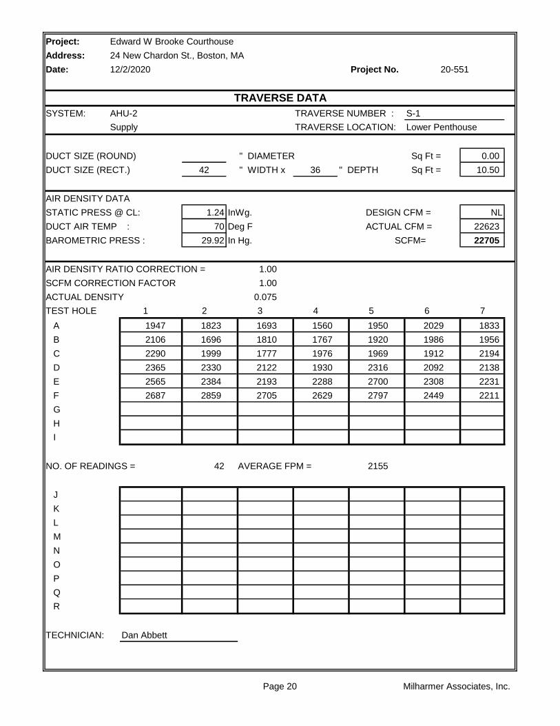
SYSTEM: AHU-2 TRAVERSE NUMBER : S-1
Supply TRAVERSE LOCATION: Lower Penthouse
DUCT SIZE (ROUND) " DIAMETER Sq Ft = 0.00
DUCT SIZE (RECT.) 42 " WIDTH x 36 " DEPTH Sq Ft = 10.50
AIR DENSITY DATA
STATIC PRESS @ CL: 1.24 InWg. DESIGN CFM = NL
DUCT AIR TEMP : 70 Deg F ACTUAL CFM = 22623
BAROMETRIC PRESS : 29.92 In Hg. SCFM= 22705
AIR DENSITY RATIO CORRECTION = 1.00
SCFM CORRECTION FACTOR 1.00
ACTUAL DENSITY 0.075
TEST HOLE 1 2 3 4 5 6 7
A 1947 1823 1693 1560 1950 2029 1833
B 2106 1696 1810 1767 1920 1986 1956
C 2290 1999 1777 1976 1969 1912 2194
D 2365 2330 2122 1930 2316 2092 2138
E 2565 2384 2193 2288 2700 2308 2231
F 2687 2859 2705 2629 2797 2449 2211
G
H
I
NO. OF READINGS = 42 AVERAGE FPM = 2155
J
K
L
M
N
O
P
Q
R
TECHNICIAN: Dan Abbett
Edward W Brooke Courthouse
24 New Chardon St., Boston, MA
12/2/2020 20-551
TRAVERSE DATA
Page 20 Milharmer Associates, Inc.
Project:
Address:
Date: Project No.
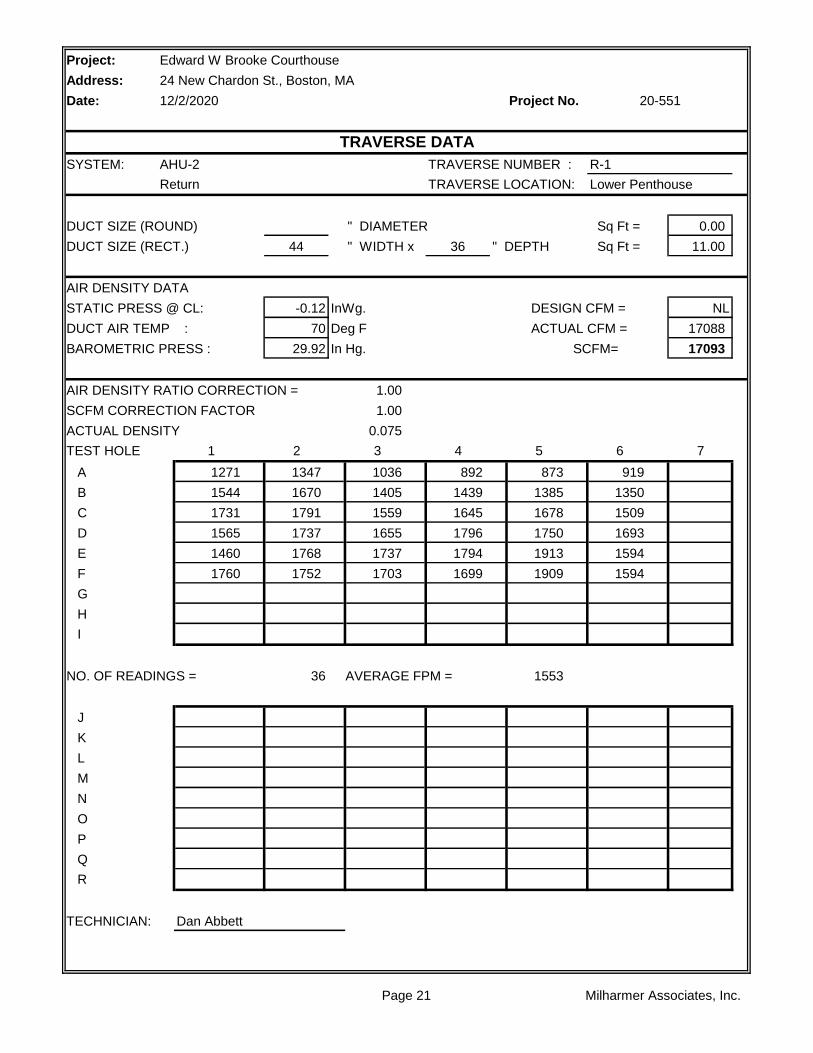
SYSTEM: AHU-2 TRAVERSE NUMBER : R-1
Return TRAVERSE LOCATION: Lower Penthouse
DUCT SIZE (ROUND) " DIAMETER Sq Ft = 0.00
DUCT SIZE (RECT.) 44 " WIDTH x 36 " DEPTH Sq Ft = 11.00
AIR DENSITY DATA
STATIC PRESS @ CL: -0.12 InWg. DESIGN CFM = NL
DUCT AIR TEMP : 70 Deg F ACTUAL CFM = 17088
BAROMETRIC PRESS : 29.92 In Hg. SCFM= 17093
AIR DENSITY RATIO CORRECTION = 1.00
SCFM CORRECTION FACTOR 1.00
ACTUAL DENSITY 0.075
TEST HOLE 1 2 3 4 5 6 7
A 1271 1347 1036 892 873 919
B 1544 1670 1405 1439 1385 1350
C 1731 1791 1559 1645 1678 1509
D 1565 1737 1655 1796 1750 1693
E 1460 1768 1737 1794 1913 1594
F 1760 1752 1703 1699 1909 1594
G
H
I
NO. OF READINGS = 36 AVERAGE FPM = 1553
J
K
L
M
N
O
P
Q
R
TECHNICIAN: Dan Abbett
Edward W Brooke Courthouse
24 New Chardon St., Boston, MA
12/2/2020 20-551
TRAVERSE DATA
Page 21 Milharmer Associates, Inc.
Project:
Address:
Date: Project No.
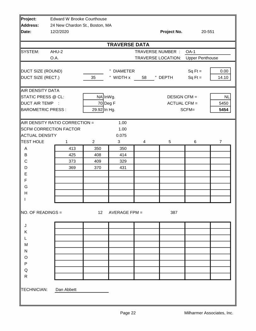
SYSTEM: AHU-2 TRAVERSE NUMBER : OA-1
O.A. TRAVERSE LOCATION: Upper Penthouse
DUCT SIZE (ROUND) " DIAMETER Sq Ft = 0.00
DUCT SIZE (RECT.) 35 " WIDTH x 58 " DEPTH Sq Ft = 14.10
AIR DENSITY DATA
STATIC PRESS @ CL: NA InWg. DESIGN CFM = NL
DUCT AIR TEMP : 70 Deg F ACTUAL CFM = 5450
BAROMETRIC PRESS : 29.92 In Hg. SCFM= 5454
AIR DENSITY RATIO CORRECTION = 1.00
SCFM CORRECTION FACTOR 1.00
ACTUAL DENSITY 0.075
TEST HOLE 1 2 3 4 5 6 7
A 413 350 350
B 425 408 414
C 373 409 329
D 369 370 431
E
F
G
H
I
NO. OF READINGS = 12 AVERAGE FPM = 387
J
K
L
M
N
O
P
Q
R
TECHNICIAN: Dan Abbett
Edward W Brooke Courthouse
24 New Chardon St., Boston, MA
12/2/2020 20-551
TRAVERSE DATA
Page 22 Milharmer Associates, Inc.
Project: Edward W Brooke Courthouse
Address: 24 New Chardon St., Boston, MA
Date: 12/2/2020 Project No.
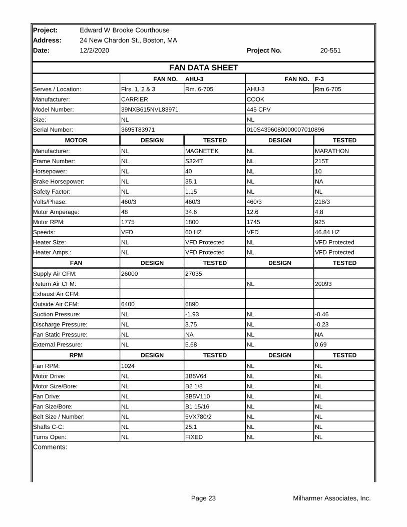
AHU-3 F-3
Rm. 6-705 Rm 6-705
TESTED TESTED
MAGNETEK MARATHON
S324T 215T
40 10
35.1 NA
1.15 NL
460/3 218/3
34.6 4.8
1800 925
60 HZ 46.84 HZ
VFD Protected VFD Protected
VFD Protected VFD Protected
TESTED TESTED
27035
20093
6890
-1.93 -0.46
3.75 -0.23
NA NA
5.68 0.69
TESTED TESTED
NL
3B5V64 NL
B2 1/8 NL
3B5V110 NL
B1 15/16 NL
5VX780/2 NL
25.1 NL
FIXED NL
Comments:
Turns Open: NL NL
Belt Size / Number: NL NL
Shafts C-C: NL NL
Fan Drive: NL NL
Fan Size/Bore: NL NL
Motor Drive: NL NL
Motor Size/Bore: NL NL
RPM DESIGN DESIGN
Fan RPM: 1024 NL
Fan Static Pressure: NL NL
External Pressure: NL NL
Suction Pressure: NL NL
Discharge Pressure: NL NL
Exhaust Air CFM:
Outside Air CFM: 6400
Supply Air CFM: 26000
Return Air CFM: NL
Heater Amps.: NL NL
FAN DESIGN DESIGN
Speeds: VFD VFD
Heater Size: NL NL
Motor Amperage: 48 12.6
Motor RPM: 1775 1745
Safety Factor: NL NL
Volts/Phase: 460/3 460/3
Horsepower: NL NL
Brake Horsepower: NL NL
Manufacturer: NL NL
Frame Number: NL NL
Serial Number: 3695T83971 010S4396080000007010896
MOTOR DESIGN DESIGN
Size: NL NL
Serves / Location: Flrs. 1, 2 & 3 AHU-3
Manufacturer: CARRIER COOK
20-551
FAN DATA SHEET
FAN NO. FAN NO.
Model Number: 39NXB615NVL83971 445 CPV
Page 23 Milharmer Associates, Inc.

Page 24 Milharmer Associates, Inc.

Project:
Address:
Date: Project No.
RA
HWC CHW
OA 1 2 3 4 5
FILTER
LOCATION STATIC
1 -1.41"
2 -1.61"
3 -1.93"
4 +3.75"
5 +2.58"
** Pressures measured wiith VAV Boxes at full cooling position.
Edward W Brooke Courthouse
24 New Chardon St., Boston, MA
12/2/2020 20-551
AHU-3 STATIC PROFILE
Page 25 Milharmer Associates, Inc.
Project:
Address:
Date: Project No.
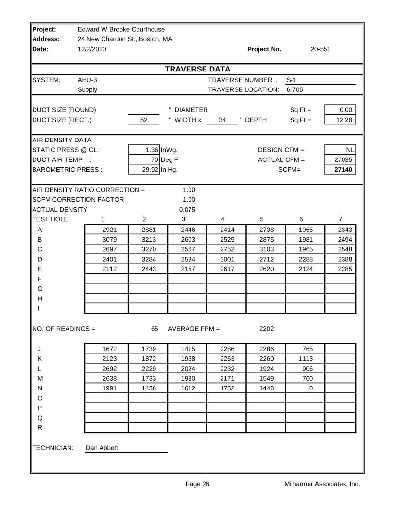
SYSTEM: AHU-3 TRAVERSE NUMBER : S-1
Supply TRAVERSE LOCATION: 6-705
DUCT SIZE (ROUND) " DIAMETER Sq Ft = 0.00
DUCT SIZE (RECT.) 52 " WIDTH x 34 " DEPTH Sq Ft = 12.28
AIR DENSITY DATA
STATIC PRESS @ CL: 1.36 InWg. DESIGN CFM = NL
DUCT AIR TEMP : 70 Deg F ACTUAL CFM = 27035
BAROMETRIC PRESS : 29.92 In Hg. SCFM= 27140
AIR DENSITY RATIO CORRECTION = 1.00
SCFM CORRECTION FACTOR 1.00
ACTUAL DENSITY 0.075
TEST HOLE 1 2 3 4 5 6 7
A 2921 2881 2446 2414 2738 1965 2343
B 3079 3213 2603 2525 2875 1981 2494
C 2697 3270 2567 2752 3103 1965 2548
D 2401 3284 2534 3001 2712 2288 2388
E 2112 2443 2157 2617 2620 2124 2285
F
G
H
I
NO. OF READINGS = 65 AVERAGE FPM = 2202
J 1672 1739 1415 2286 2286 765
K 2123 1872 1958 2263 2260 1113
L 2692 2229 2024 2232 1924 906
M 2638 1733 1930 2171 1549 760
N 1991 1436 1612 1752 1448 0
O
P
Q
R
TECHNICIAN: Dan Abbett
Edward W Brooke Courthouse
24 New Chardon St., Boston, MA
12/2/2020 20-551
TRAVERSE DATA
Page 26 Milharmer Associates, Inc.
Project:
Address:
Date: Project No.
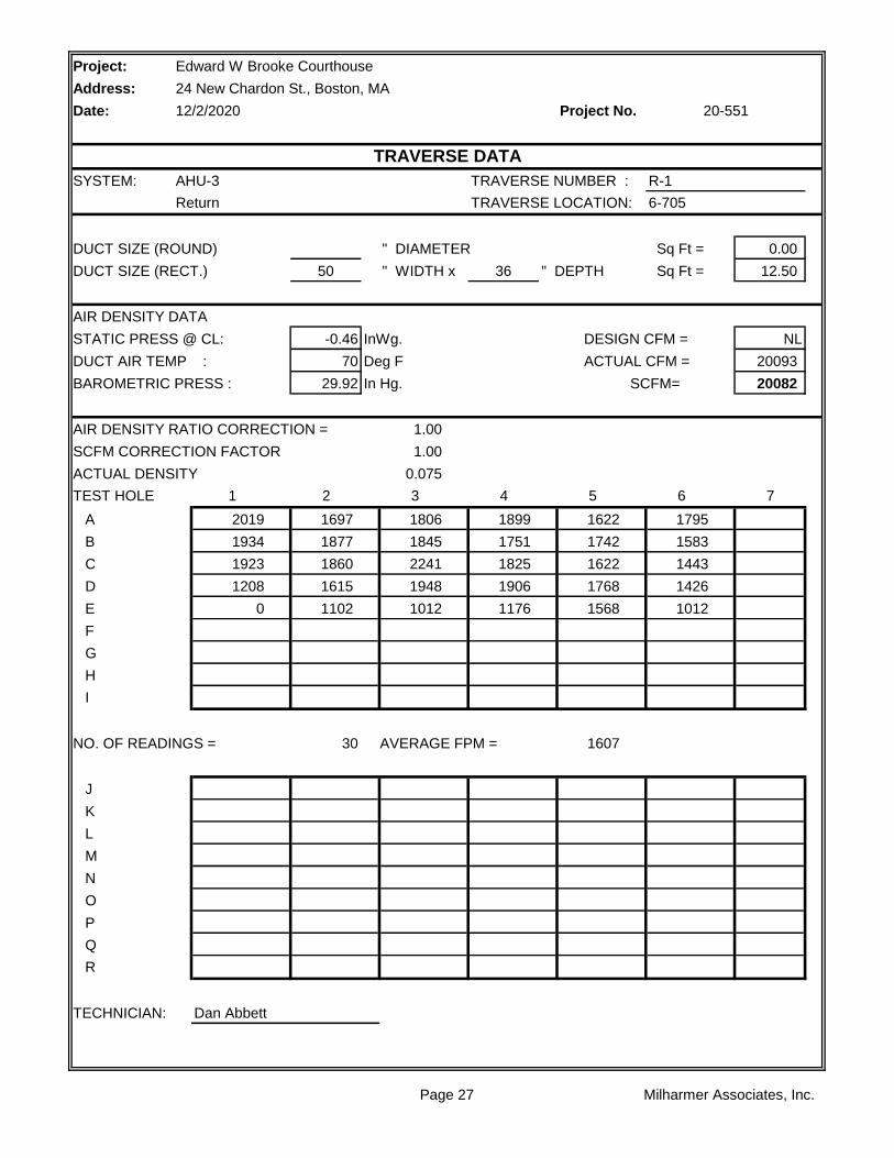
SYSTEM: AHU-3 TRAVERSE NUMBER : R-1
Return TRAVERSE LOCATION: 6-705
DUCT SIZE (ROUND) " DIAMETER Sq Ft = 0.00
DUCT SIZE (RECT.) 50 " WIDTH x 36 " DEPTH Sq Ft = 12.50
AIR DENSITY DATA
STATIC PRESS @ CL: -0.46 InWg. DESIGN CFM = NL
DUCT AIR TEMP : 70 Deg F ACTUAL CFM = 20093
BAROMETRIC PRESS : 29.92 In Hg. SCFM= 20082
AIR DENSITY RATIO CORRECTION = 1.00
SCFM CORRECTION FACTOR 1.00
ACTUAL DENSITY 0.075
TEST HOLE 1 2 3 4 5 6 7
A 2019 1697 1806 1899 1622 1795
B 1934 1877 1845 1751 1742 1583
C 1923 1860 2241 1825 1622 1443
D 1208 1615 1948 1906 1768 1426
E 0 1102 1012 1176 1568 1012
F
G
H
I
NO. OF READINGS = 30 AVERAGE FPM = 1607
J
K
L
M
N
O
P
Q
R
TECHNICIAN: Dan Abbett
Edward W Brooke Courthouse
24 New Chardon St., Boston, MA
12/2/2020 20-551
TRAVERSE DATA
Page 27 Milharmer Associates, Inc.

Project:
Address:
Date: Project No.
SYSTEM: AHU-3 TRAVERSE NUMBER : OA-1
O.A. TRAVERSE LOCATION: 6-705
DUCT SIZE (ROUND) " DIAMETER Sq Ft = 0.00
DUCT SIZE (RECT.) 96 " WIDTH x 28 " DEPTH Sq Ft = 18.67
AIR DENSITY DATA
STATIC PRESS @ CL: NA InWg. DESIGN CFM = NL
DUCT AIR TEMP : 70 Deg F ACTUAL CFM = 6890
BAROMETRIC PRESS : 29.92 In Hg. SCFM= 6894
AIR DENSITY RATIO CORRECTION = 1.00
SCFM CORRECTION FACTOR 1.00
ACTUAL DENSITY 0.075
TEST HOLE 1 2 3 4 5 6 7
A 332 284 695 118 294 198
B 531 627 489 313 251 297
C
D
E
F
G
H
I
NO. OF READINGS = 12 AVERAGE FPM = 369
J
K
L
M
N
O
P
Q
R
TECHNICIAN: Dan Abbett
Edward W Brooke Courthouse
24 New Chardon St., Boston, MA
12/2/2020 20-551
TRAVERSE DATA
Page 28 Milharmer Associates, Inc.
Project: Edward W Brooke Courthouse
Address: 24 New Chardon St., Boston, MA
Date: 12/2/2020 Project No.
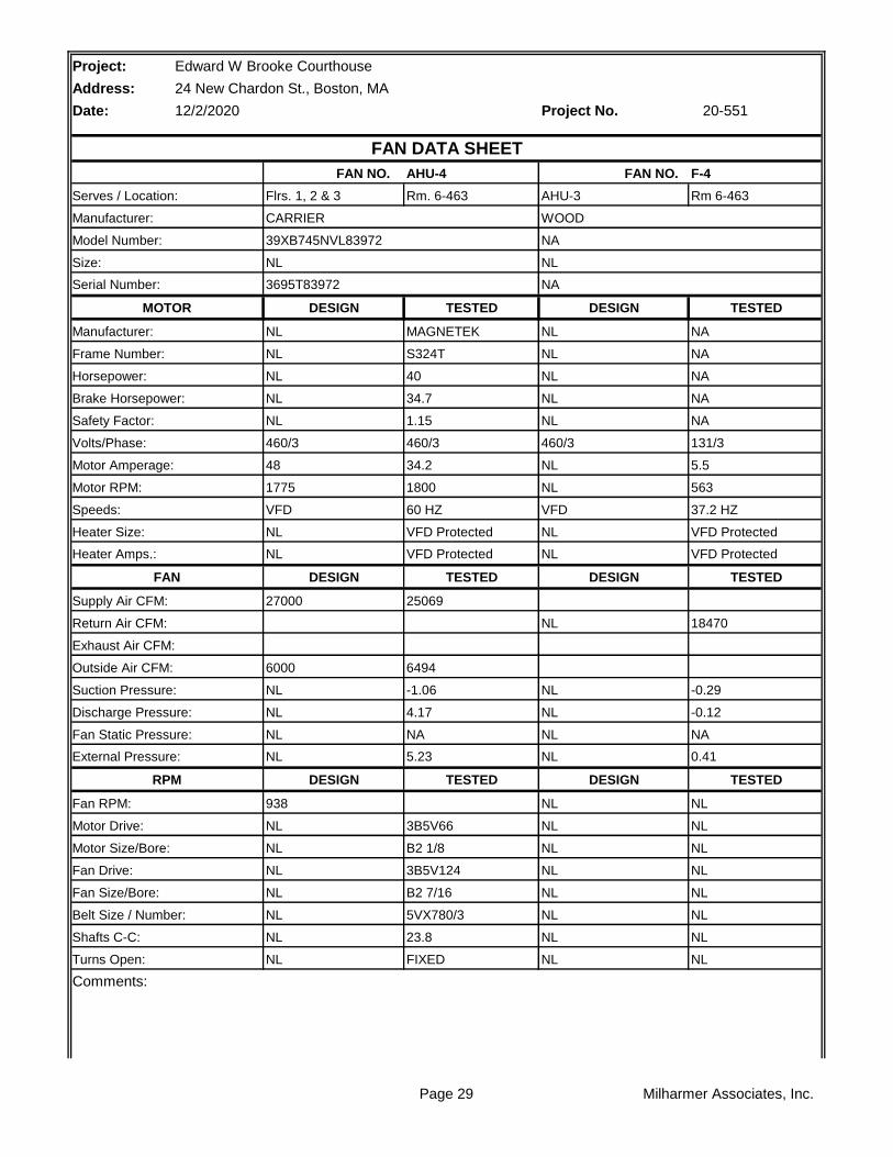
AHU-4 F-4
Rm. 6-463 Rm 6-463
TESTED TESTED
MAGNETEK NA
S324T NA
40 NA
34.7 NA
1.15 NA
460/3 131/3
34.2 5.5
1800 563
60 HZ 37.2 HZ
VFD Protected VFD Protected
VFD Protected VFD Protected
TESTED TESTED
25069
18470
6494
-1.06 -0.29
4.17 -0.12
NA NA
5.23 0.41
TESTED TESTED
NL
3B5V66 NL
B2 1/8 NL
3B5V124 NL
B2 7/16 NL
5VX780/3 NL
23.8 NL
FIXED NL
Comments:
Turns Open: NL NL
Belt Size / Number: NL NL
Shafts C-C: NL NL
Fan Drive: NL NL
Fan Size/Bore: NL NL
Motor Drive: NL NL
Motor Size/Bore: NL NL
RPM DESIGN DESIGN
Fan RPM: 938 NL
Fan Static Pressure: NL NL
External Pressure: NL NL
Suction Pressure: NL NL
Discharge Pressure: NL NL
Exhaust Air CFM:
Outside Air CFM: 6000
Supply Air CFM: 27000
Return Air CFM: NL
Heater Amps.: NL NL
FAN DESIGN DESIGN
Speeds: VFD VFD
Heater Size: NL NL
Motor Amperage: 48 NL
Motor RPM: 1775 NL
Safety Factor: NL NL
Volts/Phase: 460/3 460/3
Horsepower: NL NL
Brake Horsepower: NL NL
Manufacturer: NL NL
Frame Number: NL NL
Serial Number: 3695T83972 NA
MOTOR DESIGN DESIGN
Size: NL NL
Serves / Location: Flrs. 1, 2 & 3 AHU-3
Manufacturer: CARRIER WOOD
20-551
FAN DATA SHEET
FAN NO. FAN NO.
Model Number: 39XB745NVL83972 NA
Page 29 Milharmer Associates, Inc.

Page 30 Milharmer Associates, Inc.

Project:
Address:
Date: Project No.
RA
HWC CHW
OA 1 2 3 4 5
FILTER
LOCATION STATIC
1 -0.79"
2 -0.85"
3 -1.06"
4 +4.17"
5 +3.55"
** Pressures measured wiith VAV Boxes at full cooling position.
Edward W Brooke Courthouse
24 New Chardon St., Boston, MA
12/2/2020 20-551
AHU-4 STATIC PROFILE
Page 31 Milharmer Associates, Inc.
Project:
Address:
Date: Project No.
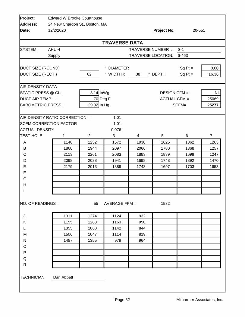
SYSTEM: AHU-4 TRAVERSE NUMBER : S-1
Supply TRAVERSE LOCATION: 6-463
DUCT SIZE (ROUND) " DIAMETER Sq Ft = 0.00
DUCT SIZE (RECT.) 62 " WIDTH x 38 " DEPTH Sq Ft = 16.36
AIR DENSITY DATA
STATIC PRESS @ CL: 3.14 InWg. DESIGN CFM = NL
DUCT AIR TEMP : 70 Deg F ACTUAL CFM = 25069
BAROMETRIC PRESS : 29.92 In Hg. SCFM= 25277
AIR DENSITY RATIO CORRECTION = 1.01
SCFM CORRECTION FACTOR 1.01
ACTUAL DENSITY 0.076
TEST HOLE 1 2 3 4 5 6 7
A 1140 1252 1572 1930 1625 1362 1263
B 1860 1944 2097 2066 1780 1368 1257
C 2113 2261 2083 1883 1839 1699 1247
D 2098 2038 1941 1698 1748 1892 1470
E 2179 2013 1889 1743 1697 1703 1653
F
G
H
I
NO. OF READINGS = 55 AVERAGE FPM = 1532
J 1311 1274 1124 932
K 1155 1288 1163 950
L 1355 1060 1142 844
M 1506 1047 1114 819
N 1487 1355 979 964
O
P
Q
R
TECHNICIAN: Dan Abbett
Edward W Brooke Courthouse
24 New Chardon St., Boston, MA
12/2/2020 20-551
TRAVERSE DATA
Page 32 Milharmer Associates, Inc.

Project:
Address:
Date: Project No.
SYSTEM: AHU-4 TRAVERSE NUMBER : R-1
Return TRAVERSE LOCATION: 6-463
DUCT SIZE (ROUND) " DIAMETER Sq Ft = 0.00
DUCT SIZE (RECT.) 54 " WIDTH x 32 " DEPTH Sq Ft = 12.00
AIR DENSITY DATA
STATIC PRESS @ CL: -0.13 InWg. DESIGN CFM = NL
DUCT AIR TEMP : 70 Deg F ACTUAL CFM = 18470
BAROMETRIC PRESS : 29.92 In Hg. SCFM= 18475
AIR DENSITY RATIO CORRECTION = 1.00
SCFM CORRECTION FACTOR 1.00
ACTUAL DENSITY 0.075
TEST HOLE 1 2 3 4 5 6 7
A 1479 1463 1713 1685 1603 1666 1954
B 1898 1938 1781 1233 1657 1397 1626
C 1895 2059 1821 1292 1823 1135 0
D 2183 1982 1409 1240 1654 1392 1331
E 1828 1720 1512 1065 1596 789 1055
F
G
H
I
NO. OF READINGS = 35 AVERAGE FPM = 1539
J
K
L
M
N
O
P
Q
R
TECHNICIAN: Dan Abbett
Edward W Brooke Courthouse
24 New Chardon St., Boston, MA
12/2/2020 20-551
TRAVERSE DATA
Page 33 Milharmer Associates, Inc.
Project:
Address:
Date: Project No.
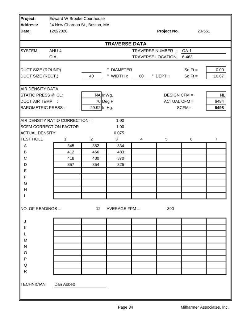
SYSTEM: AHU-4 TRAVERSE NUMBER : OA-1
O.A. TRAVERSE LOCATION: 6-463
DUCT SIZE (ROUND) " DIAMETER Sq Ft = 0.00
DUCT SIZE (RECT.) 40 " WIDTH x 60 " DEPTH Sq Ft = 16.67
AIR DENSITY DATA
STATIC PRESS @ CL: NA InWg. DESIGN CFM = NL
DUCT AIR TEMP : 70 Deg F ACTUAL CFM = 6494
BAROMETRIC PRESS : 29.92 In Hg. SCFM= 6498
AIR DENSITY RATIO CORRECTION = 1.00
SCFM CORRECTION FACTOR 1.00
ACTUAL DENSITY 0.075
TEST HOLE 1 2 3 4 5 6 7
A 345 382 334
B 412 466 483
C 418 430 370
D 357 354 325
E
F
G
H
I
NO. OF READINGS = 12 AVERAGE FPM = 390
J
K
L
M
N
O
P
Q
R
TECHNICIAN: Dan Abbett
Edward W Brooke Courthouse
24 New Chardon St., Boston, MA
12/2/2020 20-551
TRAVERSE DATA
Page 34 Milharmer Associates, Inc.

Project: Edward W Brooke Courthouse
Address: 24 New Chardon St., Boston, MA
Date: 12/2/2020 Project No.
AHU-5 F-5
Upper Penthouse Upper Penthouse
TESTED TESTED
MAGNETEK TOSHIBA
S324T 215TZ
40 10
25.35 NA
1.15 1.15
387/3 197/3
29.7 5
1501 826
50.1 HZ 41.5 HZ
VFD Protected VFD Protected
VFD Protected VFD Protected
TESTED TESTED
18666
10680
8433
-1.17 -0.51
3.13 0.05
NA NA
4.3 0.56
TESTED TESTED
NL
3B5V66 NL
B2 1/8 NL
3B5V110 NL
B1 15/16 NL
5VX780/3 NL
24.9 NL
FIXED NL
Comments:
Turns Open: NL NL
Belt Size / Number: NL NL
Shafts C-C: NL NL
Fan Drive: NL NL
Fan Size/Bore: NL NL
Motor Drive: NL NL
Motor Size/Bore: NL NL
RPM DESIGN DESIGN
Fan RPM: 938 NL
Fan Static Pressure: NL NL
External Pressure: NL NL
Suction Pressure: NL NL
Discharge Pressure: NL NL
Exhaust Air CFM:
Outside Air CFM: 8000
Supply Air CFM: 21000
Return Air CFM: NL
Heater Amps.: NL NL
FAN DESIGN DESIGN
Speeds: VFD VFD
Heater Size: NL NL
Motor Amperage: 48 12
Motor RPM: 1775 1745
Safety Factor: NL NL
Volts/Phase: 460/3 460/3
Horsepower: NL NL
Brake Horsepower: NL NL
Manufacturer: NL NL
Frame Number: NL NL
Serial Number: 3695T83973 96363H 10HP
MOTOR DESIGN DESIGN
Size: NL NL
Serves / Location: Flrs. 4 & 5 AHU-5
Manufacturer: CARRIER WOOD
20-551
FAN DATA SHEET
FAN NO. FAN NO.
Model Number: 39NXB515NVB83973 38J1/2 23P/A
Page 35 Milharmer Associates, Inc.

Page 36 Milharmer Associates, Inc.
Project:
Address:
Date: Project No.
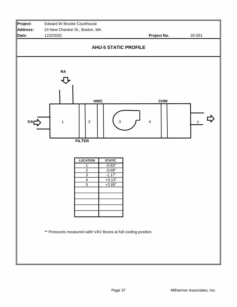
RA
HWC CHW
OA 1 2 3 4 5
FILTER
LOCATION STATIC
1 -0.83"
2 -0.99"
3 -1.17"
4 +3.13"
5 +2.65"
** Pressures measured wiith VAV Boxes at full cooling position.
Edward W Brooke Courthouse
24 New Chardon St., Boston, MA
12/2/2020 20-551
AHU-5 STATIC PROFILE
Page 37 Milharmer Associates, Inc.
Project:
Address:
Date: Project No.
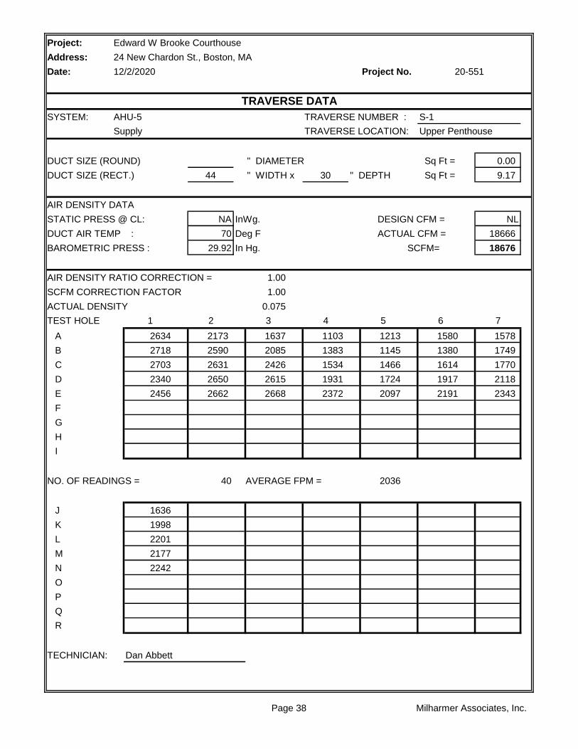
SYSTEM: AHU-5 TRAVERSE NUMBER : S-1
Supply TRAVERSE LOCATION: Upper Penthouse
DUCT SIZE (ROUND) " DIAMETER Sq Ft = 0.00
DUCT SIZE (RECT.) 44 " WIDTH x 30 " DEPTH Sq Ft = 9.17
AIR DENSITY DATA
STATIC PRESS @ CL: NA InWg. DESIGN CFM = NL
DUCT AIR TEMP : 70 Deg F ACTUAL CFM = 18666
BAROMETRIC PRESS : 29.92 In Hg. SCFM= 18676
AIR DENSITY RATIO CORRECTION = 1.00
SCFM CORRECTION FACTOR 1.00
ACTUAL DENSITY 0.075
TEST HOLE 1 2 3 4 5 6 7
A 2634 2173 1637 1103 1213 1580 1578
B 2718 2590 2085 1383 1145 1380 1749
C 2703 2631 2426 1534 1466 1614 1770
D 2340 2650 2615 1931 1724 1917 2118
E 2456 2662 2668 2372 2097 2191 2343
F
G
H
I
NO. OF READINGS = 40 AVERAGE FPM = 2036
J 1636
K 1998
L 2201
M 2177
N 2242
O
P
Q
R
TECHNICIAN: Dan Abbett
Edward W Brooke Courthouse
24 New Chardon St., Boston, MA
12/2/2020 20-551
TRAVERSE DATA
Page 38 Milharmer Associates, Inc.

Project:
Address:
Date: Project No.
SYSTEM: AHU-5 TRAVERSE NUMBER : R-1
Return TRAVERSE LOCATION: Upper Penthouse
DUCT SIZE (ROUND) " DIAMETER Sq Ft = 0.00
DUCT SIZE (RECT.) 48 " WIDTH x 30 " DEPTH Sq Ft = 10.00
AIR DENSITY DATA
STATIC PRESS @ CL: NA InWg. DESIGN CFM = NL
DUCT AIR TEMP : 70 Deg F ACTUAL CFM = 10680
BAROMETRIC PRESS : 29.92 In Hg. SCFM= 10686
AIR DENSITY RATIO CORRECTION = 1.00
SCFM CORRECTION FACTOR 1.00
ACTUAL DENSITY 0.075
TEST HOLE 1 2 3 4 5 6 7
A 1089 1022 1135 1112 1052 988
B 1110 1122 1131 1070 1027 1023
C 1149 1132 996 1069 1035 1019
D 1464 1194 934 976 968 1050
E 1211 1019 972 929 1057 987
F
G
H
I
NO. OF READINGS = 30 AVERAGE FPM = 1068
J
K
L
M
N
O
P
Q
R
TECHNICIAN: Dan Abbett
Edward W Brooke Courthouse
24 New Chardon St., Boston, MA
12/2/2020 20-551
TRAVERSE DATA
Page 39 Milharmer Associates, Inc.
Project:
Address:
Date: Project No.
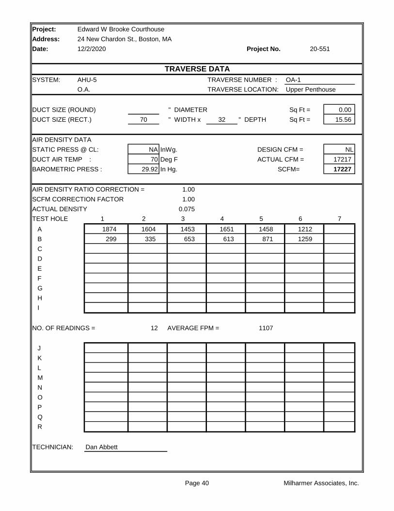
SYSTEM: AHU-5 TRAVERSE NUMBER : OA-1
O.A. TRAVERSE LOCATION: Upper Penthouse
DUCT SIZE (ROUND) " DIAMETER Sq Ft = 0.00
DUCT SIZE (RECT.) 70 " WIDTH x 32 " DEPTH Sq Ft = 15.56
AIR DENSITY DATA
STATIC PRESS @ CL: NA InWg. DESIGN CFM = NL
DUCT AIR TEMP : 70 Deg F ACTUAL CFM = 17217
BAROMETRIC PRESS : 29.92 In Hg. SCFM= 17227
AIR DENSITY RATIO CORRECTION = 1.00
SCFM CORRECTION FACTOR 1.00
ACTUAL DENSITY 0.075
TEST HOLE 1 2 3 4 5 6 7
A 1874 1604 1453 1651 1458 1212
B 299 335 653 613 871 1259
C
D
E
F
G
H
I
NO. OF READINGS = 12 AVERAGE FPM = 1107
J
K
L
M
N
O
P
Q
R
TECHNICIAN: Dan Abbett
Edward W Brooke Courthouse
24 New Chardon St., Boston, MA
12/2/2020 20-551
TRAVERSE DATA
Page 40 Milharmer Associates, Inc.

Project: Edward W Brooke Courthouse
Address: 24 New Chardon St., Boston, MA
Date: 12/2/2020 Project No.
AHU-6 F-6
Lower Penthouse Lower Penthouse
TESTED TESTED
BALDOR TOSHIBA
326T 254TZ
50 15
37 NA
1.15 1.15
429/3 164
39.1 6.1
1645 703
54.84 HZ 23.45 HZ
VFD Protected VFD Protected
VFD Protected VFD Protected
TESTED TESTED
24778
13657
11122
-1.98 -0.57
3.13 -1.06
NA NA
5.11 1.63
TESTED TESTED
NL
3B5V86 NL
B2 1/8 NL
3B5V154 NL
B2 7/16 NL
5VX850/3 NL
23 1/2 NL
FIXED NL
Comments:
Turns Open: NL NL
Belt Size / Number: NL NL
Shafts C-C: NL NL
Fan Drive: NL NL
Fan Size/Bore: NL NL
Motor Drive: NL NL
Motor Size/Bore: NL NL
RPM DESIGN DESIGN
Fan RPM: 982 NL
Fan Static Pressure: NL NL
External Pressure: NL NL
Suction Pressure: NL NL
Discharge Pressure: NL NL
Exhaust Air CFM:
Outside Air CFM: 11000
Supply Air CFM: 27400
Return Air CFM: NL
Heater Amps.: NL NL
FAN DESIGN DESIGN
Speeds: VFD VFD
Heater Size: NL NL
Motor Amperage: 57 18.5
Motor RPM: 1775 1775
Safety Factor: NL NL
Volts/Phase: 460/3 460/3
Horsepower: NL NL
Brake Horsepower: NL NL
Manufacturer: NL NL
Frame Number: NL NL
Serial Number: 3695T83974 963632H 15HP
MOTOR DESIGN DESIGN
Size: NL NL
Serves / Location: Flrs. 4 & 5 AHU-6
Manufacturer: CARRIER WOOD
20-551
FAN DATA SHEET
FAN NO. FAN NO.
Model Number: 39NXB745NBL83974 36JG 15P/A
Page 41 Milharmer Associates, Inc.

Page 42 Milharmer Associates, Inc.

Project:
Address:
Date: Project No.
RA
HWC CHW
OA 1 2 3 4 5
FILTER
LOCATION STATIC
1 -1.74"
2 -1.88"
3 -1.98"
4 +3.13"
5 +2.65"
** Pressures measured wiith VAV Boxes at full cooling position.
Edward W Brooke Courthouse
24 New Chardon St., Boston, MA
12/2/2020 20-551
AHU-6 STATIC PROFILE
Page 43 Milharmer Associates, Inc.
Project:
Address:
Date: Project No.
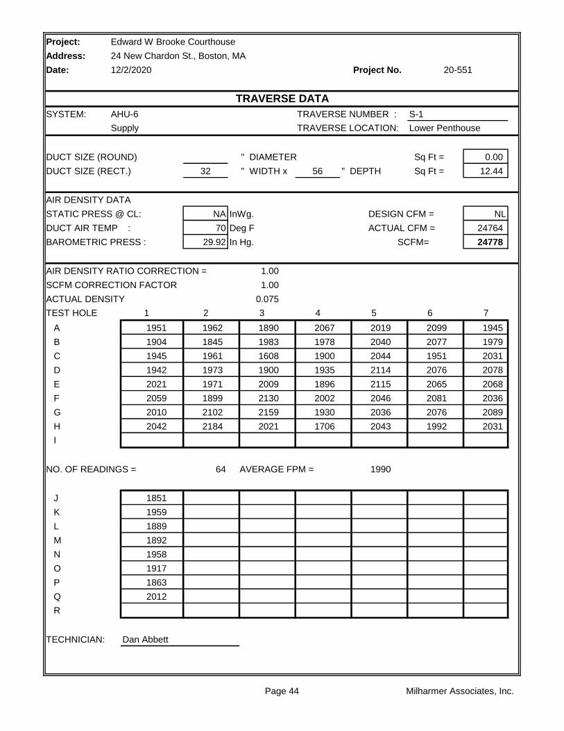
SYSTEM: AHU-6 TRAVERSE NUMBER : S-1
Supply TRAVERSE LOCATION: Lower Penthouse
DUCT SIZE (ROUND) " DIAMETER Sq Ft = 0.00
DUCT SIZE (RECT.) 32 " WIDTH x 56 " DEPTH Sq Ft = 12.44
AIR DENSITY DATA
STATIC PRESS @ CL: NA InWg. DESIGN CFM = NL
DUCT AIR TEMP : 70 Deg F ACTUAL CFM = 24764
BAROMETRIC PRESS : 29.92 In Hg. SCFM= 24778
AIR DENSITY RATIO CORRECTION = 1.00
SCFM CORRECTION FACTOR 1.00
ACTUAL DENSITY 0.075
TEST HOLE 1 2 3 4 5 6 7
A 1951 1962 1890 2067 2019 2099 1945
B 1904 1845 1983 1978 2040 2077 1979
C 1945 1961 1608 1900 2044 1951 2031
D 1942 1973 1900 1935 2114 2076 2078
E 2021 1971 2009 1896 2115 2065 2068
F 2059 1899 2130 2002 2046 2081 2036
G 2010 2102 2159 1930 2036 2076 2089
H 2042 2184 2021 1706 2043 1992 2031
I
NO. OF READINGS = 64 AVERAGE FPM = 1990
J 1851
K 1959
L 1889
M 1892
N 1958
O 1917
P 1863
Q 2012
R
TECHNICIAN: Dan Abbett
Edward W Brooke Courthouse
24 New Chardon St., Boston, MA
12/2/2020 20-551
TRAVERSE DATA
Page 44 Milharmer Associates, Inc.
Project:
Address:
Date: Project No.
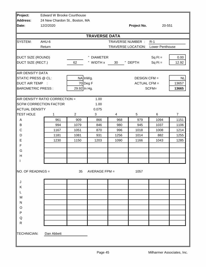
SYSTEM: AHU-6 TRAVERSE NUMBER : R-1
Return TRAVERSE LOCATION: Lower Penthouse
DUCT SIZE (ROUND) " DIAMETER Sq Ft = 0.00
DUCT SIZE (RECT.) 62 " WIDTH x 30 " DEPTH Sq Ft = 12.92
AIR DENSITY DATA
STATIC PRESS @ CL: NA InWg. DESIGN CFM = NL
DUCT AIR TEMP : 70 Deg F ACTUAL CFM = 13657
BAROMETRIC PRESS : 29.92 In Hg. SCFM= 13665
AIR DENSITY RATIO CORRECTION = 1.00
SCFM CORRECTION FACTOR 1.00
ACTUAL DENSITY 0.075
TEST HOLE 1 2 3 4 5 6 7
A 961 909 866 968 979 1094 1151
B 994 1079 846 980 945 1037 1106
C 1167 1051 870 996 1018 1008 1214
D 1181 1081 931 1256 1014 882 1255
E 1230 1150 1203 1090 1166 1043 1285
F
G
H
I
NO. OF READINGS = 35 AVERAGE FPM = 1057
J
K
L
M
N
O
P
Q
R
TECHNICIAN: Dan Abbett
Edward W Brooke Courthouse
24 New Chardon St., Boston, MA
12/2/2020 20-551
TRAVERSE DATA
Page 45 Milharmer Associates, Inc.

Project:
Address:
Date: Project No.
SYSTEM: AHU-6 TRAVERSE NUMBER : OA-1
O.A. TRAVERSE LOCATION: Lower Penthouse
DUCT SIZE (ROUND) " DIAMETER Sq Ft = 0.00
DUCT SIZE (RECT.) 38 " WIDTH x 66 " DEPTH Sq Ft = 17.42
AIR DENSITY DATA
STATIC PRESS @ CL: NA InWg. DESIGN CFM = NL
DUCT AIR TEMP : 70 Deg F ACTUAL CFM = 11116
BAROMETRIC PRESS : 29.92 In Hg. SCFM= 11122
AIR DENSITY RATIO CORRECTION = 1.00
SCFM CORRECTION FACTOR 1.00
ACTUAL DENSITY 0.075
TEST HOLE 1 2 3 4 5 6 7
A 728 418 607
B 781 485 549
C 816 646 596
D 762 644 627
E
F
G
H
I
NO. OF READINGS = 12 AVERAGE FPM = 638
J
K
L
M
N
O
P
Q
R
TECHNICIAN: Dan Abbett
Edward W Brooke Courthouse
24 New Chardon St., Boston, MA
12/2/2020 20-551
TRAVERSE DATA
Page 46 Milharmer Associates, Inc.
Project: Edward W Brooke Courthouse
Address: 24 New Chardon St., Boston, MA
Date: 12/2/2020 Project No.
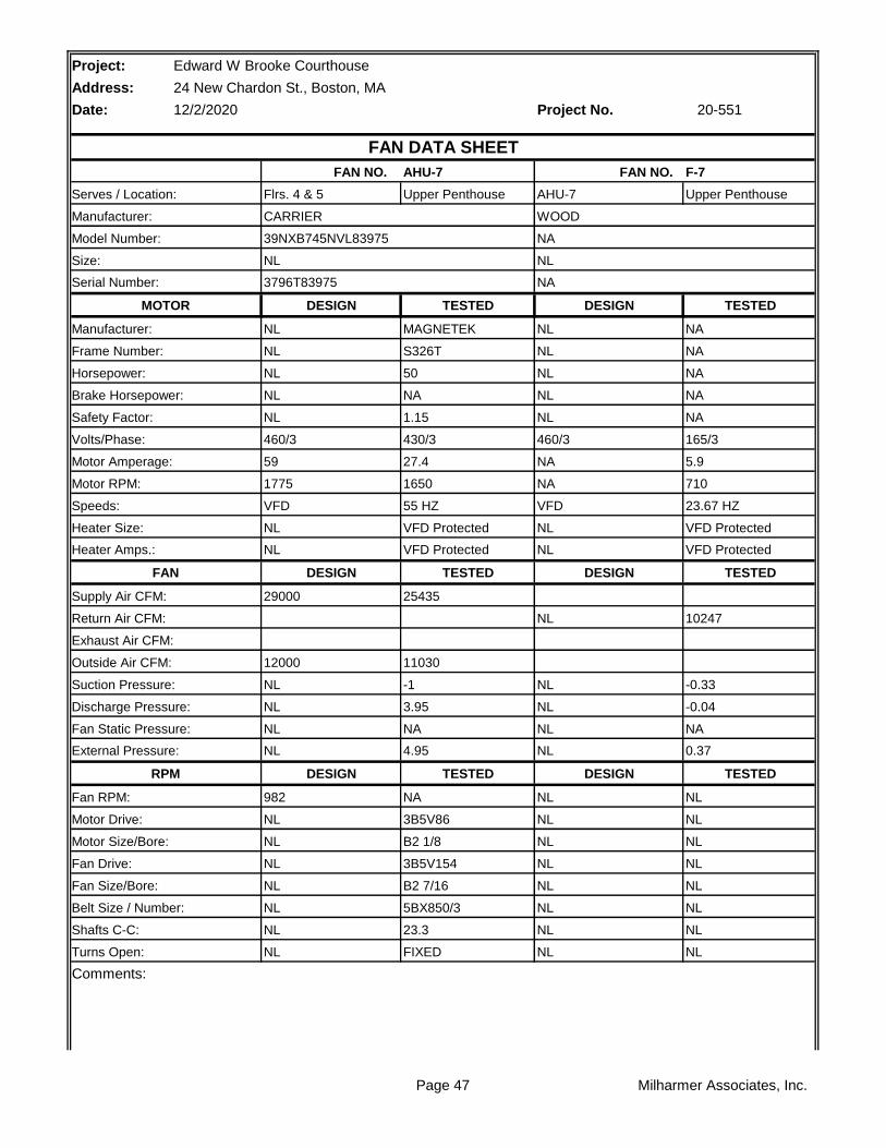
AHU-7 F-7
Upper Penthouse Upper Penthouse
TESTED TESTED
MAGNETEK NA
S326T NA
50 NA
NA NA
1.15 NA
430/3 165/3
27.4 5.9
1650 710
55 HZ 23.67 HZ
VFD Protected VFD Protected
VFD Protected VFD Protected
TESTED TESTED
25435
10247
11030
-1 -0.33
3.95 -0.04
NA NA
4.95 0.37
TESTED TESTED
NA NL
3B5V86 NL
B2 1/8 NL
3B5V154 NL
B2 7/16 NL
5BX850/3 NL
23.3 NL
FIXED NL
Comments:
20-551
FAN DATA SHEET
FAN NO. FAN NO.
Model Number: 39NXB745NVL83975 NA
Size: NL NL
Serves / Location: Flrs. 4 & 5 AHU-7
Manufacturer: CARRIER WOOD
Manufacturer: NL NL
Frame Number: NL NL
Serial Number: 3796T83975 NA
MOTOR DESIGN DESIGN
Safety Factor: NL NL
Volts/Phase: 460/3 460/3
Horsepower: NL NL
Brake Horsepower: NL NL
Speeds: VFD VFD
Heater Size: NL NL
Motor Amperage: 59 NA
Motor RPM: 1775 NA
Supply Air CFM: 29000
Return Air CFM: NL
Heater Amps.: NL NL
FAN DESIGN DESIGN
Suction Pressure: NL NL
Discharge Pressure: NL NL
Exhaust Air CFM:
Outside Air CFM: 12000
RPM DESIGN DESIGN
Fan RPM: 982 NL
Fan Static Pressure: NL NL
External Pressure: NL NL
Fan Drive: NL NL
Fan Size/Bore: NL NL
Motor Drive: NL NL
Motor Size/Bore: NL NL
Turns Open: NL NL
Belt Size / Number: NL NL
Shafts C-C: NL NL
Page 47 Milharmer Associates, Inc.

Page 48 Milharmer Associates, Inc.

Project:
Address:
Date: Project No.
RA
HWC CHW
OA 1 2 3 4 5
FILTER
LOCATION STATIC
1 -0.68"
2 -0.78"
3 -1.00"
4 +3.95"
5 +3.29"
** Pressures measured wiith VAV Boxes at full cooling position.
Edward W Brooke Courthouse
24 New Chardon St., Boston, MA
12/2/2020 20-551
AHU-7 STATIC PROFILE
Page 49 Milharmer Associates, Inc.
Project:
Address:
Date: Project No.
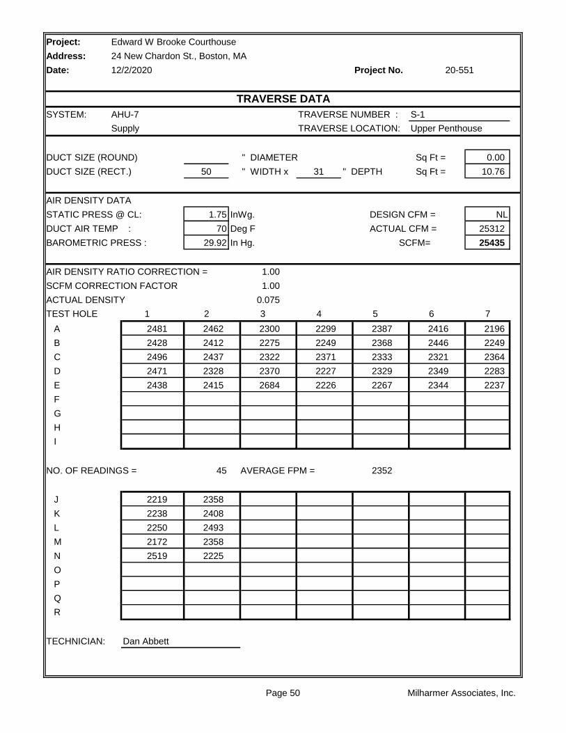
SYSTEM: AHU-7 TRAVERSE NUMBER : S-1
Supply TRAVERSE LOCATION: Upper Penthouse
DUCT SIZE (ROUND) " DIAMETER Sq Ft = 0.00
DUCT SIZE (RECT.) 50 " WIDTH x 31 " DEPTH Sq Ft = 10.76
AIR DENSITY DATA
STATIC PRESS @ CL: 1.75 InWg. DESIGN CFM = NL
DUCT AIR TEMP : 70 Deg F ACTUAL CFM = 25312
BAROMETRIC PRESS : 29.92 In Hg. SCFM= 25435
AIR DENSITY RATIO CORRECTION = 1.00
SCFM CORRECTION FACTOR 1.00
ACTUAL DENSITY 0.075
TEST HOLE 1 2 3 4 5 6 7
A 2481 2462 2300 2299 2387 2416 2196
B 2428 2412 2275 2249 2368 2446 2249
C 2496 2437 2322 2371 2333 2321 2364
D 2471 2328 2370 2227 2329 2349 2283
E 2438 2415 2684 2226 2267 2344 2237
F
G
H
I
NO. OF READINGS = 45 AVERAGE FPM = 2352
J 2219 2358
K 2238 2408
L 2250 2493
M 2172 2358
N 2519 2225
O
P
Q
R
TECHNICIAN: Dan Abbett
Edward W Brooke Courthouse
24 New Chardon St., Boston, MA
12/2/2020 20-551
TRAVERSE DATA
Page 50 Milharmer Associates, Inc.
Project:
Address:
Date: Project No.
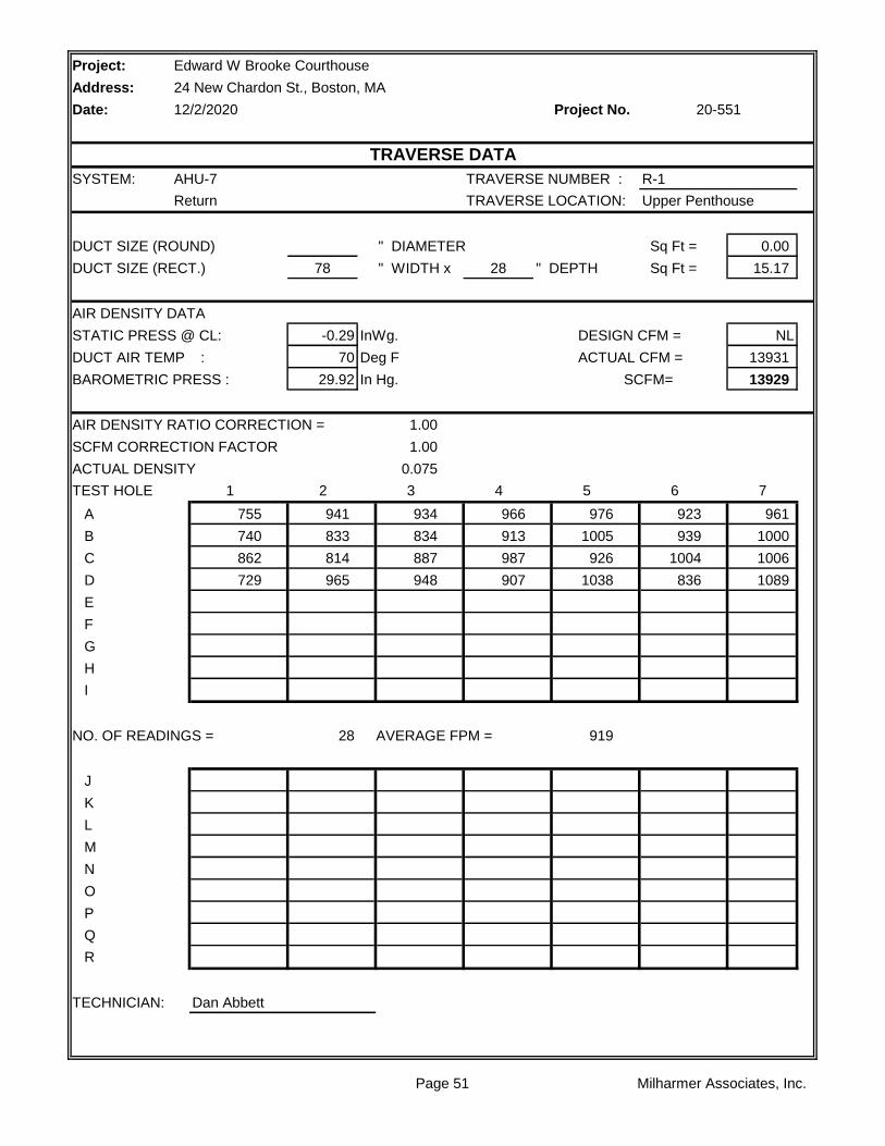
SYSTEM: AHU-7 TRAVERSE NUMBER : R-1
Return TRAVERSE LOCATION: Upper Penthouse
DUCT SIZE (ROUND) " DIAMETER Sq Ft = 0.00
DUCT SIZE (RECT.) 78 " WIDTH x 28 " DEPTH Sq Ft = 15.17
AIR DENSITY DATA
STATIC PRESS @ CL: -0.29 InWg. DESIGN CFM = NL
DUCT AIR TEMP : 70 Deg F ACTUAL CFM = 13931
BAROMETRIC PRESS : 29.92 In Hg. SCFM= 13929
AIR DENSITY RATIO CORRECTION = 1.00
SCFM CORRECTION FACTOR 1.00
ACTUAL DENSITY 0.075
TEST HOLE 1 2 3 4 5 6 7
A 755 941 934 966 976 923 961
B 740 833 834 913 1005 939 1000
C 862 814 887 987 926 1004 1006
D 729 965 948 907 1038 836 1089
E
F
G
H
I
NO. OF READINGS = 28 AVERAGE FPM = 919
J
K
L
M
N
O
P
Q
R
TECHNICIAN: Dan Abbett
Edward W Brooke Courthouse
24 New Chardon St., Boston, MA
12/2/2020 20-551
TRAVERSE DATA
Page 51 Milharmer Associates, Inc.

Project:
Address:
Date: Project No.
SYSTEM: AHU-7 TRAVERSE NUMBER : OA-1
O.A. TRAVERSE LOCATION: Upper Penthouse
DUCT SIZE (ROUND) " DIAMETER Sq Ft = 0.00
DUCT SIZE (RECT.) 66 " WIDTH x 46 " DEPTH Sq Ft = 21.08
AIR DENSITY DATA
STATIC PRESS @ CL: NA InWg. DESIGN CFM = NL
DUCT AIR TEMP : 70 Deg F ACTUAL CFM = 11030
BAROMETRIC PRESS : 29.92 In Hg. SCFM= 11036
AIR DENSITY RATIO CORRECTION = 1.00
SCFM CORRECTION FACTOR 1.00
ACTUAL DENSITY 0.075
TEST HOLE 1 2 3 4 5 6 7
A 468 438 517 465
B 596 388 622 608
C 510 542 606 519
D
E
F
G
H
I
NO. OF READINGS = 12 AVERAGE FPM = 523
J
K
L
M
N
O
P
Q
R
TECHNICIAN: Dan Abbett
Edward W Brooke Courthouse
24 New Chardon St., Boston, MA
12/2/2020 20-551
TRAVERSE DATA
Page 52 Milharmer Associates, Inc.
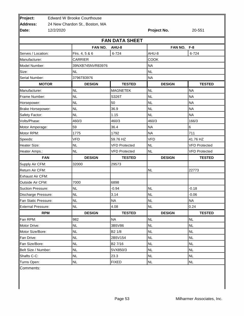
Project: Edward W Brooke Courthouse
Address: 24 New Chardon St., Boston, MA
Date: 12/2/2020 Project No.
AHU-8 F-8
6-724 6-724
TESTED TESTED
MAGNETEK NA
S326T NA
50 NA
36.9 NA
1.15 NA
460/3 166/3
36.4 6
1792 711
59.76 HZ 41.76 HZ
VFD Protected VFD Protected
VFD Protected VFD Protected
TESTED TESTED
29573
22773
6898
-0.94 -0.18
3.14 -0.06
NA NA
4.08 0.24
TESTED TESTED
NA NL
3B5V86 NL
B2 1/8 NL
2B5V154 NL
B2 7/16 NL
5VX850/3 NL
23.3 NL
FIXED NL
Comments:
20-551
FAN DATA SHEET
FAN NO. FAN NO.
Model Number: 39NXB745NVR83976 NA
Size: NL NL
Serves / Location: Flrs. 4, 5 & 6 AHU-8
Manufacturer: CARRIER COOK
Manufacturer: NL NL
Frame Number: NL NL
Serial Number: 3796T83976 NA
MOTOR DESIGN DESIGN
Safety Factor: NL NL
Volts/Phase: 460/3 460/3
Horsepower: NL NL
Brake Horsepower: NL NL
Speeds: VFD VFD
Heater Size: NL NL
Motor Amperage: 59 NA
Motor RPM: 1775 NA
Supply Air CFM: 32000
Return Air CFM: NL
Heater Amps.: NL NL
FAN DESIGN DESIGN
Suction Pressure: NL NL
Discharge Pressure: NL NL
Exhaust Air CFM:
Outside Air CFM: 7000
RPM DESIGN DESIGN
Fan RPM: 982 NL
Fan Static Pressure: NL NL
External Pressure: NL NL
Fan Drive: NL NL
Fan Size/Bore: NL NL
Motor Drive: NL NL
Motor Size/Bore: NL NL
Turns Open: NL NL
Belt Size / Number: NL NL
Shafts C-C: NL NL
Page 53 Milharmer Associates, Inc.

Page 54 Milharmer Associates, Inc.

Project:
Address:
Date: Project No.
RA
HWC CHW
OA 1 2 3 4 5
FILTER
LOCATION STATIC
1 -0.67"
2 -0.75"
3 -0.94"
4 +3.14"
5 +2.50"
** Pressures measured wiith VAV Boxes at full cooling position.
Edward W Brooke Courthouse
24 New Chardon St., Boston, MA
12/2/2020 20-551
AHU-8 STATIC PROFILE
Page 55 Milharmer Associates, Inc.
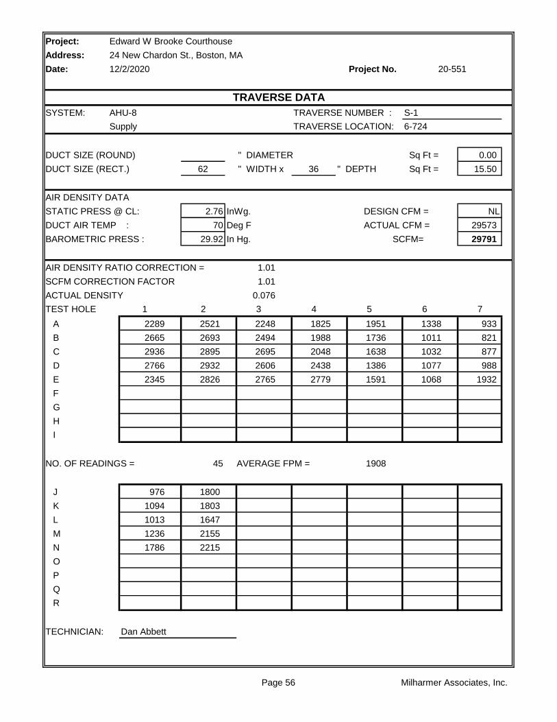
Project:
Address:
Date: Project No.
SYSTEM: AHU-8 TRAVERSE NUMBER : S-1
Supply TRAVERSE LOCATION: 6-724
DUCT SIZE (ROUND) " DIAMETER Sq Ft = 0.00
DUCT SIZE (RECT.) 62 " WIDTH x 36 " DEPTH Sq Ft = 15.50
AIR DENSITY DATA
STATIC PRESS @ CL: 2.76 InWg. DESIGN CFM = NL
DUCT AIR TEMP : 70 Deg F ACTUAL CFM = 29573
BAROMETRIC PRESS : 29.92 In Hg. SCFM= 29791
AIR DENSITY RATIO CORRECTION = 1.01
SCFM CORRECTION FACTOR 1.01
ACTUAL DENSITY 0.076
TEST HOLE 1 2 3 4 5 6 7
A 2289 2521 2248 1825 1951 1338 933
B 2665 2693 2494 1988 1736 1011 821
C 2936 2895 2695 2048 1638 1032 877
D 2766 2932 2606 2438 1386 1077 988
E 2345 2826 2765 2779 1591 1068 1932
F
G
H
I
NO. OF READINGS = 45 AVERAGE FPM = 1908
J 976 1800
K 1094 1803
L 1013 1647
M 1236 2155
N 1786 2215
O
P
Q
R
TECHNICIAN: Dan Abbett
Edward W Brooke Courthouse
24 New Chardon St., Boston, MA
12/2/2020 20-551
TRAVERSE DATA
Page 56 Milharmer Associates, Inc.
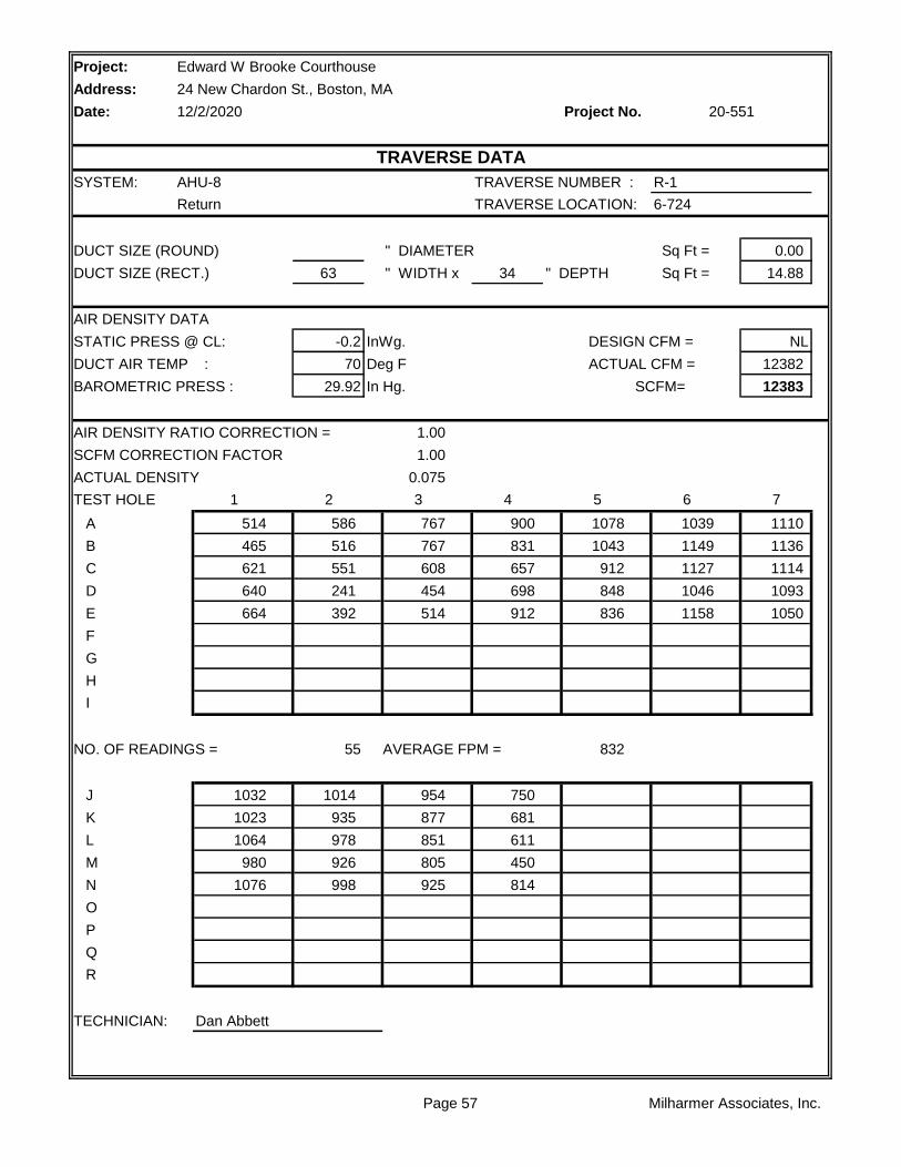
Project:
Address:
Date: Project No.
SYSTEM: AHU-8 TRAVERSE NUMBER : R-1
Return TRAVERSE LOCATION: 6-724
DUCT SIZE (ROUND) " DIAMETER Sq Ft = 0.00
DUCT SIZE (RECT.) 63 " WIDTH x 34 " DEPTH Sq Ft = 14.88
AIR DENSITY DATA
STATIC PRESS @ CL: -0.2 InWg. DESIGN CFM = NL
DUCT AIR TEMP : 70 Deg F ACTUAL CFM = 12382
BAROMETRIC PRESS : 29.92 In Hg. SCFM= 12383
AIR DENSITY RATIO CORRECTION = 1.00
SCFM CORRECTION FACTOR 1.00
ACTUAL DENSITY 0.075
TEST HOLE 1 2 3 4 5 6 7
A 514 586 767 900 1078 1039 1110
B 465 516 767 831 1043 1149 1136
C 621 551 608 657 912 1127 1114
D 640 241 454 698 848 1046 1093
E 664 392 514 912 836 1158 1050
F
G
H
I
NO. OF READINGS = 55 AVERAGE FPM = 832
J 1032 1014 954 750
K 1023 935 877 681
L 1064 978 851 611
M 980 926 805 450
N 1076 998 925 814
O
P
Q
R
TECHNICIAN: Dan Abbett
Edward W Brooke Courthouse
24 New Chardon St., Boston, MA
12/2/2020 20-551
TRAVERSE DATA
Page 57 Milharmer Associates, Inc.

Project: Edward W Brooke Courthouse
Address: 24 New Chardon St., Boston, MA
Date: 12/2/2020 Project No.
AHU-9 F-9
Upper Penthouse Upper Penthouse
TESTED TESTED
BALDOR NA
286T NA
30 NA
23.9 NA
1.15 NA
381/3 145/3
28.4 3.3
1478 625
49.3 Hz 37.8 Hz
VFD Protected VFD Protected
VFD Protected VFD Protected
TESTED TESTED
16546
12999
3804
-1.07 -0.01
2.68 0.03
NA NA
3.75 0.13
TESTED TESTED
NA NL
2B5V80 NL
B1 7/8 NL
2B5V124 NL
B1 15/16 NL
5VX730/2 NL
20.2 NL
FIXED NL
Comments:
20-551
FAN DATA SHEET
FAN NO. FAN NO.
Model Number: 39NXD495NVL83977 NA
Size: NL NL
Serves / Location: Flr. 6 AHU-9
Manufacturer: CARRIER WOODS
Manufacturer: NL NL
Frame Number: NL NL
Serial Number: 3796T83977 NA
MOTOR DESIGN DESIGN
Safety Factor: NL NL
Volts/Phase: 460/3 460/3
Horsepower: NL NL
Brake Horsepower: NL NL
Speeds: VFD VFD
Heater Size: NL NL
Motor Amperage: 36 NA
Motor RPM: 1780 NA
Supply Air CFM: 17000
Return Air CFM: NL
Heater Amps.: NL NL
FAN DESIGN DESIGN
Suction Pressure: NL NL
Discharge Pressure: NL NL
Exhaust Air CFM:
Outside Air CFM: 4000
RPM DESIGN DESIGN
Fan RPM: 982 NL
Fan Static Pressure: NL NL
External Pressure: NL NL
Fan Drive: NL NL
Fan Size/Bore: NL NL
Motor Drive: NL NL
Motor Size/Bore: NL NL
Turns Open: NL NL
Belt Size / Number: NL NL
Shafts C-C: NL NL
Page 58 Milharmer Associates, Inc.

Page 59 Milharmer Associates, Inc.

Project:
Address:
Date: Project No.
RA
HWC CHW
OA 1 2 3 4 5
FILTER
LOCATION STATIC
1 -0.77"
2 -1.01"
3 -1.07"
4 +2.68"
5 +2.10"
** Pressures measured wiith VAV Boxes at full cooling position.
Edward W Brooke Courthouse
24 New Chardon St., Boston, MA
12/2/2020 20-551
AHU-9 STATIC PROFILE
Page 60 Milharmer Associates, Inc.

Project:
Address:
Date: Project No.
SYSTEM: AHU-9 TRAVERSE NUMBER : S-1
Supply TRAVERSE LOCATION: Upper Penthouse
DUCT SIZE (ROUND) " DIAMETER Sq Ft = 0.00
DUCT SIZE (RECT.) 38 " WIDTH x 30 " DEPTH Sq Ft = 7.92
AIR DENSITY DATA
STATIC PRESS @ CL: 1.1 InWg. DESIGN CFM = NL
DUCT AIR TEMP : 70 Deg F ACTUAL CFM = 16546
BAROMETRIC PRESS : 29.92 In Hg. SCFM= 16600
AIR DENSITY RATIO CORRECTION = 1.00
SCFM CORRECTION FACTOR 1.00
ACTUAL DENSITY 0.075
TEST HOLE 1 2 3 4 5 6 7
A 2331 2551 2511 2260 2654 2541
B 2464 2317 2375 2504 2288 2318
C 2349 1896 2429 2319 2383 2397
D 1856 1374 1839 1740 2130 2060
E 1382 739 1636 1899 1519 1638
F
G
H
I
NO. OF READINGS = 30 AVERAGE FPM = 2090
J
K
L
M
N
O
P
Q
R
TECHNICIAN: Dan Abbett
Edward W Brooke Courthouse
24 New Chardon St., Boston, MA
12/2/2020 20-551
TRAVERSE DATA
Page 61 Milharmer Associates, Inc.

Project:
Address:
Date: Project No.
SYSTEM: AHU-9 TRAVERSE NUMBER : R-1
Return TRAVERSE LOCATION: Upper Penthouse
DUCT SIZE (ROUND) " DIAMETER Sq Ft = 0.00
DUCT SIZE (RECT.) 50 " WIDTH x 30 " DEPTH Sq Ft = 10.42
AIR DENSITY DATA
STATIC PRESS @ CL: -0.08 InWg. DESIGN CFM = NL
DUCT AIR TEMP : 70 Deg F ACTUAL CFM = 12999
BAROMETRIC PRESS : 29.92 In Hg. SCFM= 13004
AIR DENSITY RATIO CORRECTION = 1.00
SCFM CORRECTION FACTOR 1.00
ACTUAL DENSITY 0.075
TEST HOLE 1 2 3 4 5 6 7
A 1428 1555 967 964 1014 867
B 1972 1523 1466 1116 1076 1158
C 1855 1213 1251 1107 1050 1193
D 1536 1071 1263 1022 1082 1188
E 1833 1384 1176 777 1132 1199
F
G
H
I
NO. OF READINGS = 30 AVERAGE FPM = 1248
J
K
L
M
N
O
P
Q
R
TECHNICIAN: Dan Abbett
Edward W Brooke Courthouse
24 New Chardon St., Boston, MA
12/2/2020 20-551
TRAVERSE DATA
Page 62 Milharmer Associates, Inc.
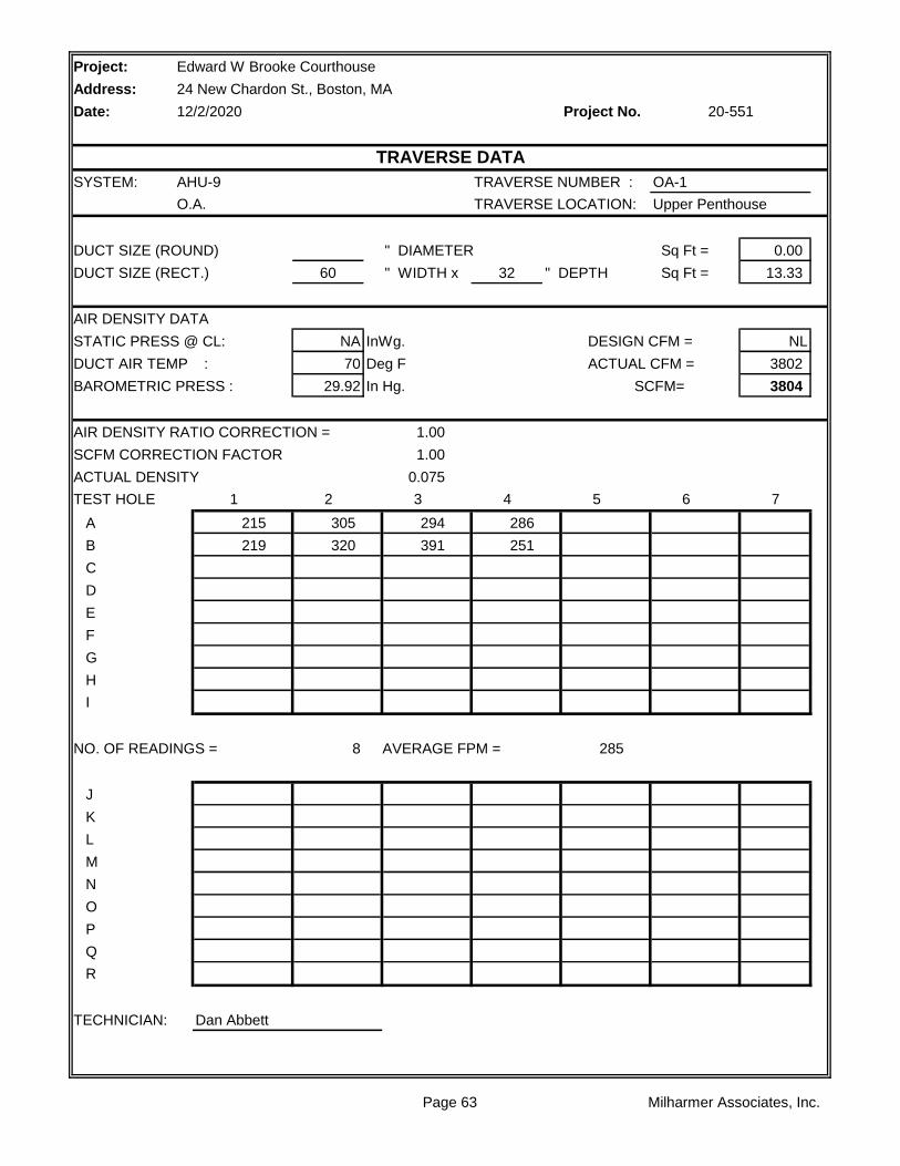
Project:
Address:
Date: Project No.
SYSTEM: AHU-9 TRAVERSE NUMBER : OA-1
O.A. TRAVERSE LOCATION: Upper Penthouse
DUCT SIZE (ROUND) " DIAMETER Sq Ft = 0.00
DUCT SIZE (RECT.) 60 " WIDTH x 32 " DEPTH Sq Ft = 13.33
AIR DENSITY DATA
STATIC PRESS @ CL: NA InWg. DESIGN CFM = NL
DUCT AIR TEMP : 70 Deg F ACTUAL CFM = 3802
BAROMETRIC PRESS : 29.92 In Hg. SCFM= 3804
AIR DENSITY RATIO CORRECTION = 1.00
SCFM CORRECTION FACTOR 1.00
ACTUAL DENSITY 0.075
TEST HOLE 1 2 3 4 5 6 7
A 215 305 294 286
B 219 320 391 251
C
D
E
F
G
H
I
NO. OF READINGS = 8 AVERAGE FPM = 285
J
K
L
M
N
O
P
Q
R
TECHNICIAN: Dan Abbett
Edward W Brooke Courthouse
24 New Chardon St., Boston, MA
12/2/2020 20-551
TRAVERSE DATA
Page 63 Milharmer Associates, Inc.
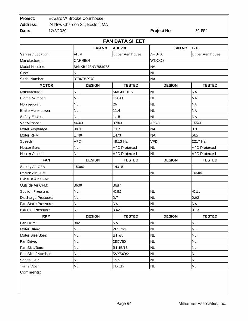
Project: Edward W Brooke Courthouse
Address: 24 New Chardon St., Boston, MA
Date: 12/2/2020 Project No.
AHU-10 F-10
Upper Penthouse Upper Penthouse
TESTED TESTED
MAGNETEK NA
S284T NA
25 NA
11.4 NA
1.15 NA
378/3 155/3
13.7 3.3
1473 665
49.13 Hz 2217 Hz
VFD Protected VFD Protected
VFD Protected VFD Protected
TESTED TESTED
14018
10509
3687
-0.92 -0.11
2.7 0.02
NA NA
3.62 0.13
TESTED TESTED
NA NL
2B5V64 NL
B1 7/8 NL
2B5V80 NL
B1 15/16 NL
5VX540/2 NL
15.5 NL
FIXED NL
Comments:
20-551
FAN DATA SHEET
FAN NO. FAN NO.
Model Number: 39NXB495NVR83978 NA
Size: NL NL
Serves / Location: Flr. 6 AHU-10
Manufacturer: CARRIER WOODS
Manufacturer: NL NL
Frame Number: NL NL
Serial Number: 3796T83978 NA
MOTOR DESIGN DESIGN
Safety Factor: NL NL
Volts/Phase: 460/3 460/3
Horsepower: NL NL
Brake Horsepower: NL NL
Speeds: VFD VFD
Heater Size: NL NL
Motor Amperage: 30.3 NA
Motor RPM: 1740 NA
Supply Air CFM: 15000
Return Air CFM: NL
Heater Amps.: NL NL
FAN DESIGN DESIGN
Suction Pressure: NL NL
Discharge Pressure: NL NL
Exhaust Air CFM:
Outside Air CFM: 3600
RPM DESIGN DESIGN
Fan RPM: 982 NL
Fan Static Pressure: NL NL
External Pressure: NL NL
Fan Drive: NL NL
Fan Size/Bore: NL NL
Motor Drive: NL NL
Motor Size/Bore: NL NL
Turns Open: NL NL
Belt Size / Number: NL NL
Shafts C-C: NL NL
Page 64 Milharmer Associates, Inc.

Page 65 Milharmer Associates, Inc.

Project:
Address:
Date: Project No.
RA
HWC CHW
OA 1 2 3 4 5
FILTER
LOCATION STATIC
1 -0.73"
2 -0.76"
3 -0.92"
4 +2.70"
5 +2.04"
** Pressures measured wiith VAV Boxes at full cooling position.
Edward W Brooke Courthouse
24 New Chardon St., Boston, MA
12/2/2020 20-551
AHU-10 STATIC PROFILE
Page 66 Milharmer Associates, Inc.
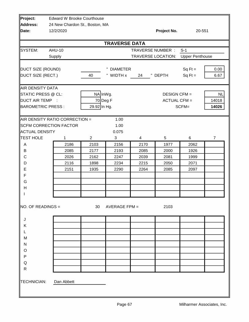
Project:
Address:
Date: Project No.
SYSTEM: AHU-10 TRAVERSE NUMBER : S-1
Supply TRAVERSE LOCATION: Upper Penthouse
DUCT SIZE (ROUND) " DIAMETER Sq Ft = 0.00
DUCT SIZE (RECT.) 40 " WIDTH x 24 " DEPTH Sq Ft = 6.67
AIR DENSITY DATA
STATIC PRESS @ CL: NA InWg. DESIGN CFM = NL
DUCT AIR TEMP : 70 Deg F ACTUAL CFM = 14018
BAROMETRIC PRESS : 29.92 In Hg. SCFM= 14026
AIR DENSITY RATIO CORRECTION = 1.00
SCFM CORRECTION FACTOR 1.00
ACTUAL DENSITY 0.075
TEST HOLE 1 2 3 4 5 6 7
A 2186 2103 2156 2170 1977 2062
B 2085 2177 2193 2085 2000 1926
C 2026 2162 2247 2039 2081 1999
D 2116 1898 2234 2215 2050 2071
E 2151 1935 2290 2264 2085 2097
F
G
H
I
NO. OF READINGS = 30 AVERAGE FPM = 2103
J
K
L
M
N
O
P
Q
R
TECHNICIAN: Dan Abbett
Edward W Brooke Courthouse
24 New Chardon St., Boston, MA
12/2/2020 20-551
TRAVERSE DATA
Page 67 Milharmer Associates, Inc.

Project:
Address:
Date: Project No.
SYSTEM: AHU-10 TRAVERSE NUMBER : R-1
Return TRAVERSE LOCATION: Upper Penthouse
DUCT SIZE (ROUND) " DIAMETER Sq Ft = 0.00
DUCT SIZE (RECT.) 44 " WIDTH x 28 " DEPTH Sq Ft = 8.56
AIR DENSITY DATA
STATIC PRESS @ CL: NA InWg. DESIGN CFM = NL
DUCT AIR TEMP : 70 Deg F ACTUAL CFM = 10509
BAROMETRIC PRESS : 29.92 In Hg. SCFM= 10514
AIR DENSITY RATIO CORRECTION = 1.00
SCFM CORRECTION FACTOR 1.00
ACTUAL DENSITY 0.075
TEST HOLE 1 2 3 4 5 6 7
A 1157 1418 1150 1109 1221 1026
B 1300 1456 1200 1121 1200 1056
C 1420 1609 1122 1100 1333 1000
D 1265 1521 1279 1168 1321 1012
E 1108 1439 1318 1109 1288 1022
F
G
H
I
NO. OF READINGS = 30 AVERAGE FPM = 1228
J
K
L
M
N
O
P
Q
R
TECHNICIAN: Dan Abbett
Edward W Brooke Courthouse
24 New Chardon St., Boston, MA
12/2/2020 20-551
TRAVERSE DATA
Page 68 Milharmer Associates, Inc.

Project:
Address:
Date: Project No.
SYSTEM: AHU-10 TRAVERSE NUMBER : OA-1
O.A. TRAVERSE LOCATION: Upper Penthouse
DUCT SIZE (ROUND) " DIAMETER Sq Ft = 0.00
DUCT SIZE (RECT.) 52 " WIDTH x 26 " DEPTH Sq Ft = 9.39
AIR DENSITY DATA
STATIC PRESS @ CL: NA InWg. DESIGN CFM = NL
DUCT AIR TEMP : 70 Deg F ACTUAL CFM = 3687
BAROMETRIC PRESS : 29.92 In Hg. SCFM= 3690
AIR DENSITY RATIO CORRECTION = 1.00
SCFM CORRECTION FACTOR 1.00
ACTUAL DENSITY 0.075
TEST HOLE 1 2 3 4 5 6 7
A 325 363 419 465
B 320 344 387 520
C
D
E
F
G
H
I
NO. OF READINGS = 8 AVERAGE FPM = 393
J
K
L
M
N
O
P
Q
R
TECHNICIAN: Dan Abbett
Edward W Brooke Courthouse
24 New Chardon St., Boston, MA
12/2/2020 20-551
TRAVERSE DATA
Page 69 Milharmer Associates, Inc.
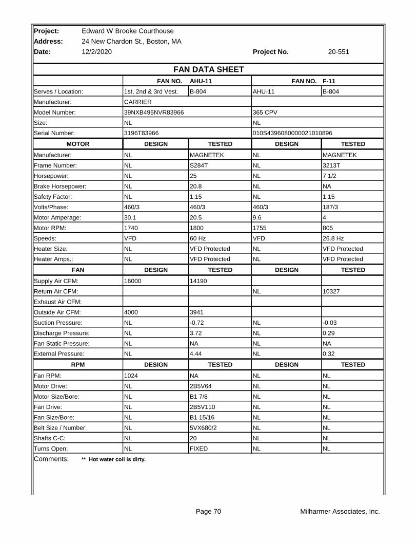
Project: Edward W Brooke Courthouse
Address: 24 New Chardon St., Boston, MA
Date: 12/2/2020 Project No.
AHU-11 F-11
B-804 B-804
TESTED TESTED
MAGNETEK MAGNETEK
S284T 3213T
25 7 1/2
20.8 NA
1.15 1.15
460/3 187/3
20.5 4
1800 805
60 Hz 26.8 Hz
VFD Protected VFD Protected
VFD Protected VFD Protected
TESTED TESTED
14190
10327
3941
-0.72 -0.03
3.72 0.29
NA NA
4.44 0.32
TESTED TESTED
NA NL
2B5V64 NL
B1 7/8 NL
2B5V110 NL
B1 15/16 NL
5VX680/2 NL
20 NL
FIXED NL
Comments:
Turns Open: NL NL
** Hot water coil is dirty.
Belt Size / Number: NL NL
Shafts C-C: NL NL
Fan Drive: NL NL
Fan Size/Bore: NL NL
Motor Drive: NL NL
Motor Size/Bore: NL NL
RPM DESIGN DESIGN
Fan RPM: 1024 NL
Fan Static Pressure: NL NL
External Pressure: NL NL
Suction Pressure: NL NL
Discharge Pressure: NL NL
Exhaust Air CFM:
Outside Air CFM: 4000
Supply Air CFM: 16000
Return Air CFM: NL
Heater Amps.: NL NL
FAN DESIGN DESIGN
Speeds: VFD VFD
Heater Size: NL NL
Motor Amperage: 30.1 9.6
Motor RPM: 1740 1755
Safety Factor: NL NL
Volts/Phase: 460/3 460/3
Horsepower: NL NL
Brake Horsepower: NL NL
Manufacturer: NL NL
Frame Number: NL NL
Serial Number: 3196T83966 010S4396080000021010896
MOTOR DESIGN DESIGN
Size: NL NL
Serves / Location: 1st, 2nd & 3rd Vest. AHU-11
Manufacturer: CARRIER
20-551
FAN DATA SHEET
FAN NO. FAN NO.
Model Number: 39NXB495NVR83966 365 CPV
Page 70 Milharmer Associates, Inc.

Page 71 Milharmer Associates, Inc.

Project:
Address:
Date: Project No.
RA
HWC CHW
OA 1 2 3 4 5
FILTER
LOCATION STATIC
1 -0.47"
2 -0.50"
3 -0.72"
4 +3.72"
5 +3.13"
** Pressures measured wiith VAV Boxes at full cooling position.
Edward W Brooke Courthouse
24 New Chardon St., Boston, MA
12/2/2020 20-551
AHU-11 STATIC PROFILE
Page 72 Milharmer Associates, Inc.

Project:
Address:
Date: Project No.
SYSTEM: AHU-11 TRAVERSE NUMBER : S-1
Supply TRAVERSE LOCATION: B-804
DUCT SIZE (ROUND) " DIAMETER Sq Ft = 0.00
DUCT SIZE (RECT.) 22 " WIDTH x 14 " DEPTH Sq Ft = 2.14
AIR DENSITY DATA
STATIC PRESS @ CL: 1.72 InWg. DESIGN CFM = NL
DUCT AIR TEMP : 70 Deg F ACTUAL CFM = 2820
BAROMETRIC PRESS : 29.92 In Hg. SCFM= 2834
AIR DENSITY RATIO CORRECTION = 1.00
SCFM CORRECTION FACTOR 1.00
ACTUAL DENSITY 0.075
TEST HOLE 1 2 3 4 5 6 7
A 1541 1424 1239 1157 1110
B 1309 1422 1202 1163 1089
C 1384 1442 1235 1253 1329
D 1608 1532 1309 1222 1401
E
F
G
H
I
NO. OF READINGS = 20 AVERAGE FPM = 1319
J
K
L
M
N
O
P
Q
R
TECHNICIAN: Dan Abbett
Edward W Brooke Courthouse
24 New Chardon St., Boston, MA
12/2/2020 20-551
TRAVERSE DATA
Page 73 Milharmer Associates, Inc.
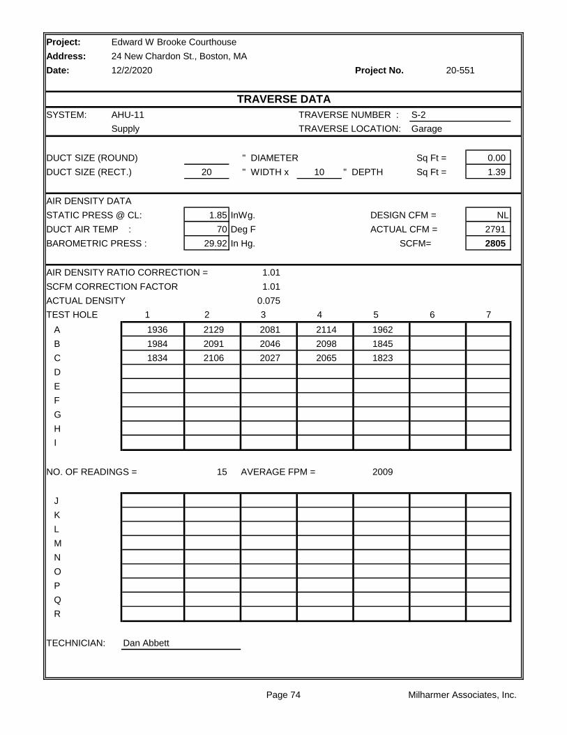
Project:
Address:
Date: Project No.
SYSTEM: AHU-11 TRAVERSE NUMBER : S-2
Supply TRAVERSE LOCATION: Garage
DUCT SIZE (ROUND) " DIAMETER Sq Ft = 0.00
DUCT SIZE (RECT.) 20 " WIDTH x 10 " DEPTH Sq Ft = 1.39
AIR DENSITY DATA
STATIC PRESS @ CL: 1.85 InWg. DESIGN CFM = NL
DUCT AIR TEMP : 70 Deg F ACTUAL CFM = 2791
BAROMETRIC PRESS : 29.92 In Hg. SCFM= 2805
AIR DENSITY RATIO CORRECTION = 1.01
SCFM CORRECTION FACTOR 1.01
ACTUAL DENSITY 0.075
TEST HOLE 1 2 3 4 5 6 7
A 1936 2129 2081 2114 1962
B 1984 2091 2046 2098 1845
C 1834 2106 2027 2065 1823
D
E
F
G
H
I
NO. OF READINGS = 15 AVERAGE FPM = 2009
J
K
L
M
N
O
P
Q
R
TECHNICIAN: Dan Abbett
Edward W Brooke Courthouse
24 New Chardon St., Boston, MA
12/2/2020 20-551
TRAVERSE DATA
Page 74 Milharmer Associates, Inc.

Project:
Address:
Date: Project No.
SYSTEM: AHU-11 TRAVERSE NUMBER : S-3
Supply TRAVERSE LOCATION: B-804
DUCT SIZE (ROUND) " DIAMETER Sq Ft = 0.00
DUCT SIZE (RECT.) 16 " WIDTH x 44 " DEPTH Sq Ft = 4.89
AIR DENSITY DATA
STATIC PRESS @ CL: 1.68 InWg. DESIGN CFM = NL
DUCT AIR TEMP : 70 Deg F ACTUAL CFM = 8579
BAROMETRIC PRESS : 29.92 In Hg. SCFM= 8620
AIR DENSITY RATIO CORRECTION = 1.00
SCFM CORRECTION FACTOR 1.00
ACTUAL DENSITY 0.075
TEST HOLE 1 2 3 4 5 6 7
A 1217 1309 1187 1007
B 1652 1400 1519 1043
C 1720 1583 1795 1304
D 1836 1890 1954 1567
E 1713 2012 2084 2197
F 2003 1783 2169 1721
G 2272 2254 2292 2016
H 1825 1809 2044 1979
I
NO. OF READINGS = 32 AVERAGE FPM = 1755
J
K
L
M
N
O
P
Q
R
TECHNICIAN: Dan Abbett
Edward W Brooke Courthouse
24 New Chardon St., Boston, MA
12/2/2020 20-551
TRAVERSE DATA
Page 75 Milharmer Associates, Inc.
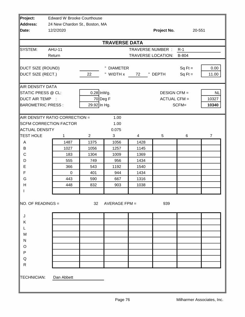
Project:
Address:
Date: Project No.
SYSTEM: AHU-11 TRAVERSE NUMBER : R-1
Return TRAVERSE LOCATION: B-804
DUCT SIZE (ROUND) " DIAMETER Sq Ft = 0.00
DUCT SIZE (RECT.) 22 " WIDTH x 72 " DEPTH Sq Ft = 11.00
AIR DENSITY DATA
STATIC PRESS @ CL: 0.28 InWg. DESIGN CFM = NL
DUCT AIR TEMP : 70 Deg F ACTUAL CFM = 10327
BAROMETRIC PRESS : 29.92 In Hg. SCFM= 10340
AIR DENSITY RATIO CORRECTION = 1.00
SCFM CORRECTION FACTOR 1.00
ACTUAL DENSITY 0.075
TEST HOLE 1 2 3 4 5 6 7
A 1487 1375 1056 1428
B 1027 1056 1257 1145
C 183 1304 1009 1369
D 555 749 956 1434
E 366 543 1192 1540
F 0 401 944 1434
G 443 590 667 1316
H 448 832 903 1038
I
NO. OF READINGS = 32 AVERAGE FPM = 939
J
K
L
M
N
O
P
Q
R
TECHNICIAN: Dan Abbett
Edward W Brooke Courthouse
24 New Chardon St., Boston, MA
12/2/2020 20-551
TRAVERSE DATA
Page 76 Milharmer Associates, Inc.
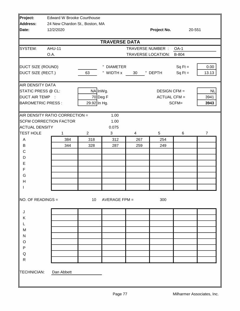
Project:
Address:
Date: Project No.
SYSTEM: AHU-11 TRAVERSE NUMBER : OA-1
O.A. TRAVERSE LOCATION: B-804
DUCT SIZE (ROUND) " DIAMETER Sq Ft = 0.00
DUCT SIZE (RECT.) 63 " WIDTH x 30 " DEPTH Sq Ft = 13.13
AIR DENSITY DATA
STATIC PRESS @ CL: NA InWg. DESIGN CFM = NL
DUCT AIR TEMP : 70 Deg F ACTUAL CFM = 3941
BAROMETRIC PRESS : 29.92 In Hg. SCFM= 3943
AIR DENSITY RATIO CORRECTION = 1.00
SCFM CORRECTION FACTOR 1.00
ACTUAL DENSITY 0.075
TEST HOLE 1 2 3 4 5 6 7
A 384 318 312 267 254
B 344 328 287 259 249
C
D
E
F
G
H
I
NO. OF READINGS = 10 AVERAGE FPM = 300
J
K
L
M
N
O
P
Q
R
TECHNICIAN: Dan Abbett
Edward W Brooke Courthouse
24 New Chardon St., Boston, MA
12/2/2020 20-551
TRAVERSE DATA
Page 77 Milharmer Associates, Inc.
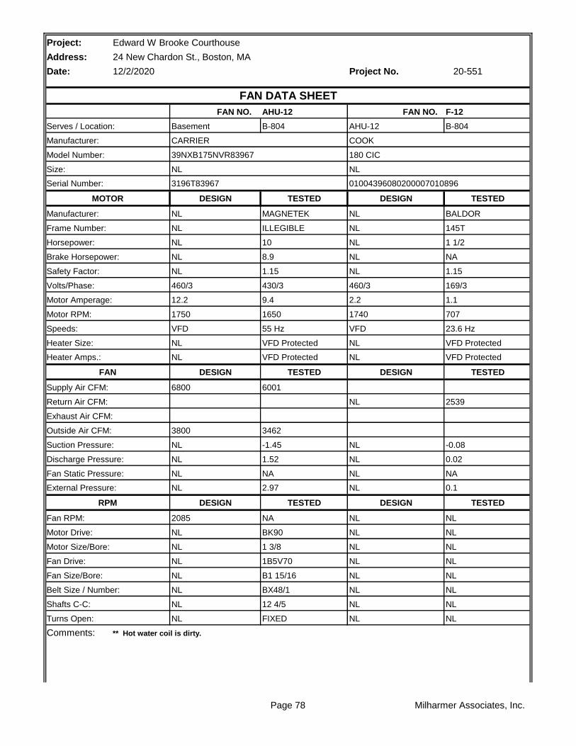
Project: Edward W Brooke Courthouse
Address: 24 New Chardon St., Boston, MA
Date: 12/2/2020 Project No.
AHU-12 F-12
B-804 B-804
TESTED TESTED
MAGNETEK BALDOR
ILLEGIBLE 145T
10 1 1/2
8.9 NA
1.15 1.15
430/3 169/3
9.4 1.1
1650 707
55 Hz 23.6 Hz
VFD Protected VFD Protected
VFD Protected VFD Protected
TESTED TESTED
6001
2539
3462
-1.45 -0.08
1.52 0.02
NA NA
2.97 0.1
TESTED TESTED
NA NL
BK90 NL
1 3/8 NL
1B5V70 NL
B1 15/16 NL
BX48/1 NL
12 4/5 NL
FIXED NL
Comments:
Turns Open: NL NL
** Hot water coil is dirty.
Belt Size / Number: NL NL
Shafts C-C: NL NL
Fan Drive: NL NL
Fan Size/Bore: NL NL
Motor Drive: NL NL
Motor Size/Bore: NL NL
RPM DESIGN DESIGN
Fan RPM: 2085 NL
Fan Static Pressure: NL NL
External Pressure: NL NL
Suction Pressure: NL NL
Discharge Pressure: NL NL
Exhaust Air CFM:
Outside Air CFM: 3800
Supply Air CFM: 6800
Return Air CFM: NL
Heater Amps.: NL NL
FAN DESIGN DESIGN
Speeds: VFD VFD
Heater Size: NL NL
Motor Amperage: 12.2 2.2
Motor RPM: 1750 1740
Safety Factor: NL NL
Volts/Phase: 460/3 460/3
Horsepower: NL NL
Brake Horsepower: NL NL
Manufacturer: NL NL
Frame Number: NL NL
Serial Number: 3196T83967 01004396080200007010896
MOTOR DESIGN DESIGN
Size: NL NL
Serves / Location: Basement AHU-12
Manufacturer: CARRIER COOK
20-551
FAN DATA SHEET
FAN NO. FAN NO.
Model Number: 39NXB175NVR83967 180 CIC
Page 78 Milharmer Associates, Inc.

Page 79 Milharmer Associates, Inc.

Project:
Address:
Date: Project No.
RA
HWC CHW
OA 1 2 3 4 5
FILTER
LOCATION STATIC
1 -1.31"
2 -1.34"
3 -1.45"
4 +1.52"
5 +1.05"
** Pressures measured wiith VAV Boxes at full cooling position.
Edward W Brooke Courthouse
24 New Chardon St., Boston, MA
12/2/2020 20-551
AHU-12 STATIC PROFILE
Page 80 Milharmer Associates, Inc.
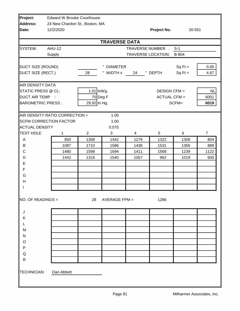
Project:
Address:
Date: Project No.
SYSTEM: AHU-12 TRAVERSE NUMBER : S-1
Supply TRAVERSE LOCATION: B-804
DUCT SIZE (ROUND) " DIAMETER Sq Ft = 0.00
DUCT SIZE (RECT.) 28 " WIDTH x 24 " DEPTH Sq Ft = 4.67
AIR DENSITY DATA
STATIC PRESS @ CL: 1.01 InWg. DESIGN CFM = NL
DUCT AIR TEMP : 70 Deg F ACTUAL CFM = 6001
BAROMETRIC PRESS : 29.92 In Hg. SCFM= 6019
AIR DENSITY RATIO CORRECTION = 1.00
SCFM CORRECTION FACTOR 1.00
ACTUAL DENSITY 0.075
TEST HOLE 1 2 3 4 5 6 7
A 850 1358 1442 1279 1322 1308 804
B 1087 1710 1586 1436 1531 1356 889
C 1480 1598 1694 1411 1568 1239 1122
D 1442 1316 1540 1057 962 1019 600
E
F
G
H
I
NO. OF READINGS = 28 AVERAGE FPM = 1286
J
K
L
M
N
O
P
Q
R
TECHNICIAN: Dan Abbett
Edward W Brooke Courthouse
24 New Chardon St., Boston, MA
12/2/2020 20-551
TRAVERSE DATA
Page 81 Milharmer Associates, Inc.

Project:
Address:
Date: Project No.
SYSTEM: AHU-12 TRAVERSE NUMBER : OA-1
O.A. TRAVERSE LOCATION: B-804
DUCT SIZE (ROUND) " DIAMETER Sq Ft = 0.00
DUCT SIZE (RECT.) 34 " WIDTH x 24 " DEPTH Sq Ft = 5.67
AIR DENSITY DATA
STATIC PRESS @ CL: -0.14 InWg. DESIGN CFM = NL
DUCT AIR TEMP : 70 Deg F ACTUAL CFM = 3462
BAROMETRIC PRESS : 29.92 In Hg. SCFM= 3463
AIR DENSITY RATIO CORRECTION = 1.00
SCFM CORRECTION FACTOR 1.00
ACTUAL DENSITY 0.075
TEST HOLE 1 2 3 4 5 6 7
A 358 259 799 831
B 223 604 844 838
C 0 777 796 868
D 243 771 766 798
E
F
G
H
I
NO. OF READINGS = 16 AVERAGE FPM = 611
J
K
L
M
N
O
P
Q
R
TECHNICIAN: Dan Abbett
Edward W Brooke Courthouse
24 New Chardon St., Boston, MA
12/2/2020 20-551
TRAVERSE DATA
Page 82 Milharmer Associates, Inc.
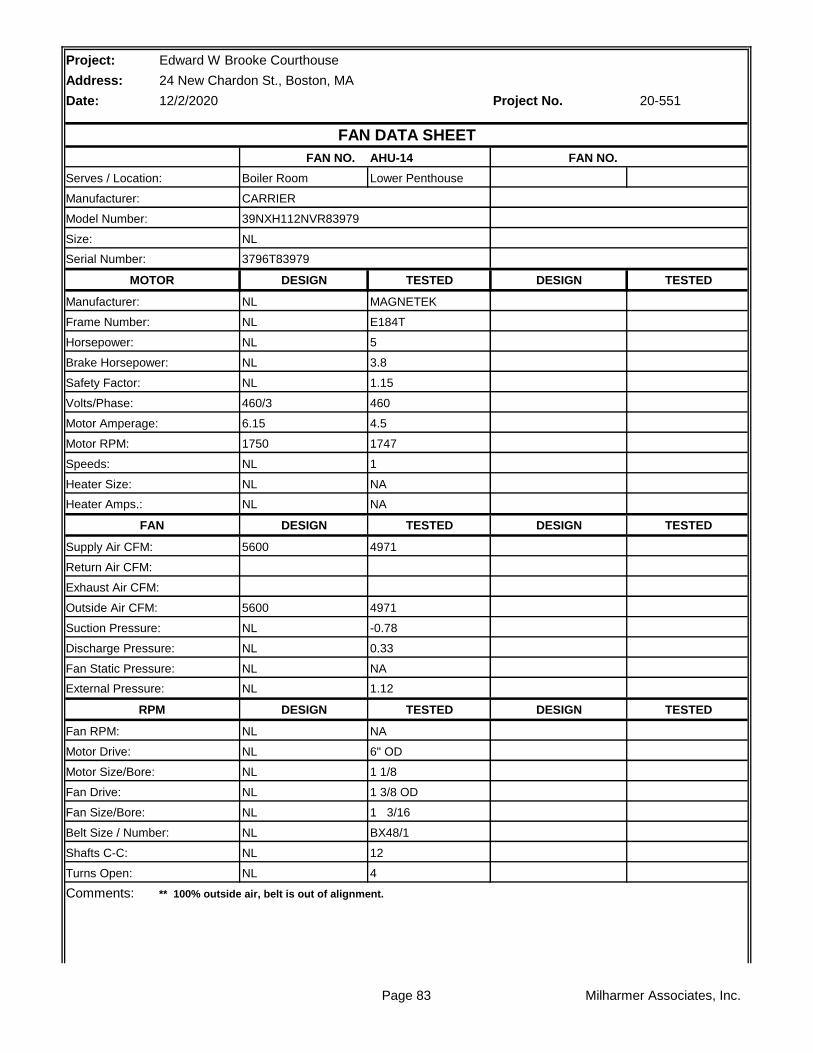
Project: Edward W Brooke Courthouse
Address: 24 New Chardon St., Boston, MA
Date: 12/2/2020 Project No.
AHU-14
Lower Penthouse
TESTED TESTED
MAGNETEK
E184T
5
3.8
1.15
460
4.5
1747
1
NA
NA
TESTED TESTED
4971
4971
-0.78
0.33
NA
1.12
TESTED TESTED
NA
6" OD
1 1/8
1 3/8 OD
1 3/16
BX48/1
12
4
Comments:
Turns Open: NL
** 100% outside air, belt is out of alignment.
Belt Size / Number: NL
Shafts C-C: NL
Fan Drive: NL
Fan Size/Bore: NL
Motor Drive: NL
Motor Size/Bore: NL
RPM DESIGN DESIGN
Fan RPM: NL
Fan Static Pressure: NL
External Pressure: NL
Suction Pressure: NL
Discharge Pressure: NL
Exhaust Air CFM:
Outside Air CFM: 5600
Supply Air CFM: 5600
Return Air CFM:
Heater Amps.: NL
FAN DESIGN DESIGN
Speeds: NL
Heater Size: NL
Motor Amperage: 6.15
Motor RPM: 1750
Safety Factor: NL
Volts/Phase: 460/3
Horsepower: NL
Brake Horsepower: NL
Manufacturer: NL
Frame Number: NL
Serial Number: 3796T83979
MOTOR DESIGN DESIGN
Size: NL
Serves / Location: Boiler Room
Manufacturer: CARRIER
20-551
FAN DATA SHEET
FAN NO. FAN NO.
Model Number: 39NXH112NVR83979
Page 83 Milharmer Associates, Inc.

Page 84 Milharmer Associates, Inc.
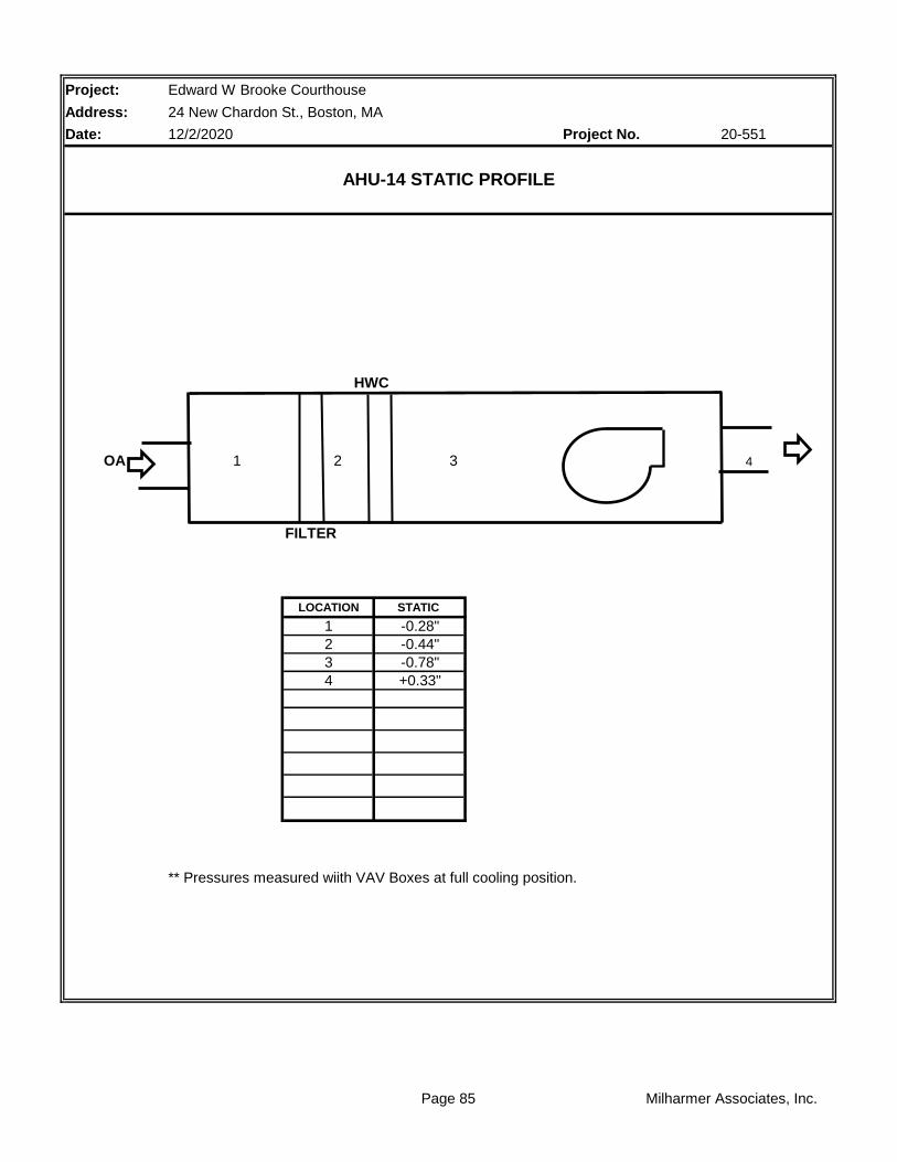
Project:
Address:
Date: Project No.
HWC
OA 1 2 3 4
FILTER
LOCATION STATIC
1 -0.28"
2 -0.44"
3 -0.78"
4 +0.33"
** Pressures measured wiith VAV Boxes at full cooling position.
Edward W Brooke Courthouse
24 New Chardon St., Boston, MA
12/2/2020 20-551
AHU-14 STATIC PROFILE
Page 85 Milharmer Associates, Inc.
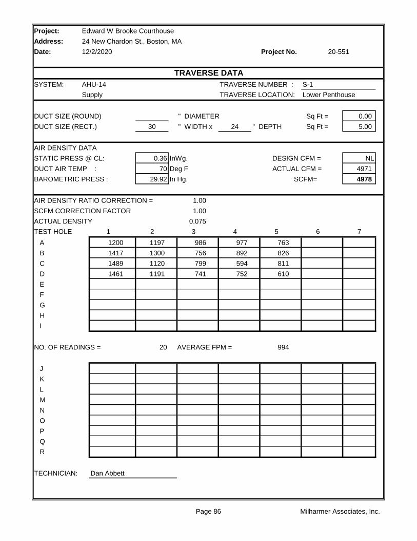
Project:
Address:
Date: Project No.
SYSTEM: AHU-14 TRAVERSE NUMBER : S-1
Supply TRAVERSE LOCATION: Lower Penthouse
DUCT SIZE (ROUND) " DIAMETER Sq Ft = 0.00
DUCT SIZE (RECT.) 30 " WIDTH x 24 " DEPTH Sq Ft = 5.00
AIR DENSITY DATA
STATIC PRESS @ CL: 0.36 InWg. DESIGN CFM = NL
DUCT AIR TEMP : 70 Deg F ACTUAL CFM = 4971
BAROMETRIC PRESS : 29.92 In Hg. SCFM= 4978
AIR DENSITY RATIO CORRECTION = 1.00
SCFM CORRECTION FACTOR 1.00
ACTUAL DENSITY 0.075
TEST HOLE 1 2 3 4 5 6 7
A 1200 1197 986 977 763
B 1417 1300 756 892 826
C 1489 1120 799 594 811
D 1461 1191 741 752 610
E
F
G
H
I
NO. OF READINGS = 20 AVERAGE FPM = 994
J
K
L
M
N
O
P
Q
R
TECHNICIAN: Dan Abbett
Edward W Brooke Courthouse
24 New Chardon St., Boston, MA
12/2/2020 20-551
TRAVERSE DATA
Page 86 Milharmer Associates, Inc.
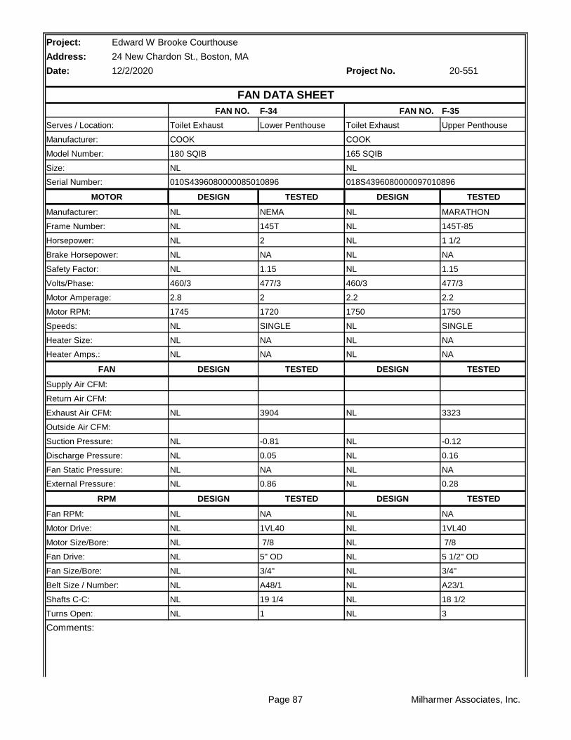
Project: Edward W Brooke Courthouse
Address: 24 New Chardon St., Boston, MA
Date: 12/2/2020 Project No.
F-34 F-35
Lower Penthouse Upper Penthouse
TESTED TESTED
NEMA MARATHON
145T 145T-85
2 1 1/2
NA NA
1.15 1.15
477/3 477/3
2 2.2
1720 1750
SINGLE SINGLE
NA NA
NA NA
TESTED TESTED
3904 3323
-0.81 -0.12
0.05 0.16
NA NA
0.86 0.28
TESTED TESTED
NA NA
1VL40 1VL40
7/8 7/8
5" OD 5 1/2" OD
3/4" 3/4"
A48/1 A23/1
19 1/4 18 1/2
1 3
Comments:
Turns Open: NL NL
Belt Size / Number: NL NL
Shafts C-C: NL NL
Fan Drive: NL NL
Fan Size/Bore: NL NL
Motor Drive: NL NL
Motor Size/Bore: NL NL
RPM DESIGN DESIGN
Fan RPM: NL NL
Fan Static Pressure: NL NL
External Pressure: NL NL
Suction Pressure: NL NL
Discharge Pressure: NL NL
Exhaust Air CFM: NL NL
Outside Air CFM:
Supply Air CFM:
Return Air CFM:
Heater Amps.: NL NL
FAN DESIGN DESIGN
Speeds: NL NL
Heater Size: NL NL
Motor Amperage: 2.8 2.2
Motor RPM: 1745 1750
Safety Factor: NL NL
Volts/Phase: 460/3 460/3
Horsepower: NL NL
Brake Horsepower: NL NL
Manufacturer: NL NL
Frame Number: NL NL
Serial Number: 010S4396080000085010896 018S4396080000097010896
MOTOR DESIGN DESIGN
Size: NL NL
Serves / Location: Toilet Exhaust Toilet Exhaust
Manufacturer: COOK COOK
20-551
FAN DATA SHEET
FAN NO. FAN NO.
Model Number: 180 SQIB 165 SQIB
Page 87 Milharmer Associates, Inc.

Page 88 Milharmer Associates, Inc.
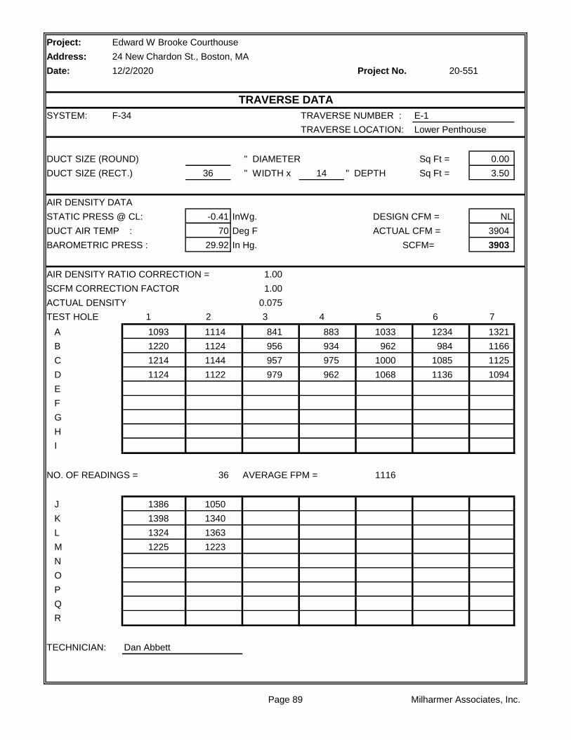
Project:
Address:
Date: Project No.
SYSTEM: F-34 TRAVERSE NUMBER : E-1
TRAVERSE LOCATION: Lower Penthouse
DUCT SIZE (ROUND) " DIAMETER Sq Ft = 0.00
DUCT SIZE (RECT.) 36 " WIDTH x 14 " DEPTH Sq Ft = 3.50
AIR DENSITY DATA
STATIC PRESS @ CL: -0.41 InWg. DESIGN CFM = NL
DUCT AIR TEMP : 70 Deg F ACTUAL CFM = 3904
BAROMETRIC PRESS : 29.92 In Hg. SCFM= 3903
AIR DENSITY RATIO CORRECTION = 1.00
SCFM CORRECTION FACTOR 1.00
ACTUAL DENSITY 0.075
TEST HOLE 1 2 3 4 5 6 7
A 1093 1114 841 883 1033 1234 1321
B 1220 1124 956 934 962 984 1166
C 1214 1144 957 975 1000 1085 1125
D 1124 1122 979 962 1068 1136 1094
E
F
G
H
I
NO. OF READINGS = 36 AVERAGE FPM = 1116
J 1386 1050
K 1398 1340
L 1324 1363
M 1225 1223
N
O
P
Q
R
TECHNICIAN: Dan Abbett
Edward W Brooke Courthouse
24 New Chardon St., Boston, MA
12/2/2020 20-551
TRAVERSE DATA
Page 89 Milharmer Associates, Inc.

Project:
Address:
Date: Project No.
SYSTEM: F-35 TRAVERSE NUMBER : E-1
TRAVERSE LOCATION: Upper Penthouse
DUCT SIZE (ROUND) " DIAMETER Sq Ft = 0.00
DUCT SIZE (RECT.) 26 " WIDTH x 16 " DEPTH Sq Ft = 2.89
AIR DENSITY DATA
STATIC PRESS @ CL: -0.74 InWg. DESIGN CFM = NL
DUCT AIR TEMP : 70 Deg F ACTUAL CFM = 3323
BAROMETRIC PRESS : 29.92 In Hg. SCFM= 3319
AIR DENSITY RATIO CORRECTION = 1.00
SCFM CORRECTION FACTOR 1.00
ACTUAL DENSITY 0.075
TEST HOLE 1 2 3 4 5 6 7
A 1257 1317 1233 1224 1071
B 1343 1303 1167 1112 1199
C 1245 1111 1132 1072 996
D 1193 1116 1028 1027 862
E
F
G
H
I
NO. OF READINGS = 20 AVERAGE FPM = 1150
J
K
L
M
N
O
P
Q
R
TECHNICIAN: Dan Abbett
Edward W Brooke Courthouse
24 New Chardon St., Boston, MA
12/2/2020 20-551
TRAVERSE DATA
Page 90 Milharmer Associates, Inc.
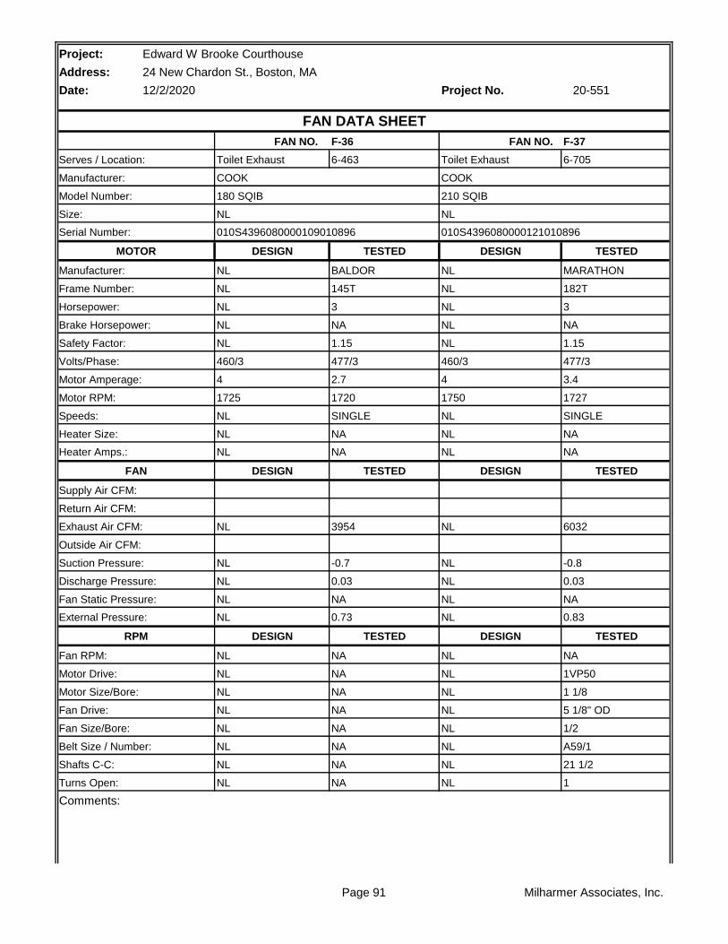
Project: Edward W Brooke Courthouse
Address: 24 New Chardon St., Boston, MA
Date: 12/2/2020 Project No.
F-36 F-37
6-463 6-705
TESTED TESTED
BALDOR MARATHON
145T 182T
3 3
NA NA
1.15 1.15
477/3 477/3
2.7 3.4
1720 1727
SINGLE SINGLE
NA NA
NA NA
TESTED TESTED
3954 6032
-0.7 -0.8
0.03 0.03
NA NA
0.73 0.83
TESTED TESTED
NA NA
NA 1VP50
NA 1 1/8
NA 5 1/8" OD
NA 1/2
NA A59/1
NA 21 1/2
NA 1
Comments:
Turns Open: NL NL
Belt Size / Number: NL NL
Shafts C-C: NL NL
Fan Drive: NL NL
Fan Size/Bore: NL NL
Motor Drive: NL NL
Motor Size/Bore: NL NL
RPM DESIGN DESIGN
Fan RPM: NL NL
Fan Static Pressure: NL NL
External Pressure: NL NL
Suction Pressure: NL NL
Discharge Pressure: NL NL
Exhaust Air CFM: NL NL
Outside Air CFM:
Supply Air CFM:
Return Air CFM:
Heater Amps.: NL NL
FAN DESIGN DESIGN
Speeds: NL NL
Heater Size: NL NL
Motor Amperage: 4 4
Motor RPM: 1725 1750
Safety Factor: NL NL
Volts/Phase: 460/3 460/3
Horsepower: NL NL
Brake Horsepower: NL NL
Manufacturer: NL NL
Frame Number: NL NL
Serial Number: 010S4396080000109010896 010S4396080000121010896
MOTOR DESIGN DESIGN
Size: NL NL
Serves / Location: Toilet Exhaust Toilet Exhaust
Manufacturer: COOK COOK
20-551
FAN DATA SHEET
FAN NO. FAN NO.
Model Number: 180 SQIB 210 SQIB
Page 91 Milharmer Associates, Inc.

Page 92 Milharmer Associates, Inc.

Project:
Address:
Date: Project No.
SYSTEM: F-36 TRAVERSE NUMBER : E-1
TRAVERSE LOCATION: 6-463
DUCT SIZE (ROUND) " DIAMETER Sq Ft = 0.00
DUCT SIZE (RECT.) 28 " WIDTH x 16 " DEPTH Sq Ft = 3.11
AIR DENSITY DATA
STATIC PRESS @ CL: -0.69 InWg. DESIGN CFM = NL
DUCT AIR TEMP : 70 Deg F ACTUAL CFM = 3954
BAROMETRIC PRESS : 29.92 In Hg. SCFM= 3950
AIR DENSITY RATIO CORRECTION = 1.00
SCFM CORRECTION FACTOR 1.00
ACTUAL DENSITY 0.075
TEST HOLE 1 2 3 4 5 6 7
A 1466 1516 1381 639 439 1396 1268
B 1518 1217 1227 704 527 1222 1420
C 1519 1128 1373 1403 842 1486 1450
D 1555 1377 1589 1553 1515 1497 1361
E
F
G
H
I
NO. OF READINGS = 28 AVERAGE FPM = 1271
J
K
L
M
N
O
P
Q
R
TECHNICIAN: Dan Abbett
Edward W Brooke Courthouse
24 New Chardon St., Boston, MA
12/2/2020 20-551
TRAVERSE DATA
Page 93 Milharmer Associates, Inc.
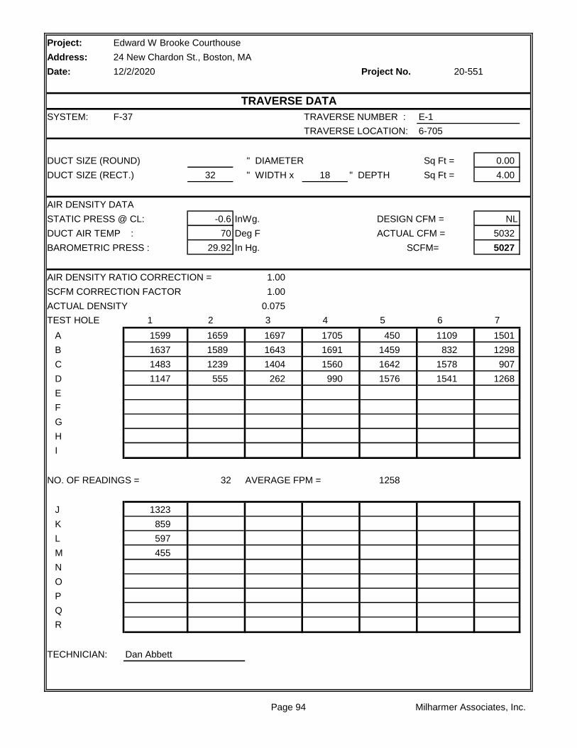
Project:
Address:
Date: Project No.
SYSTEM: F-37 TRAVERSE NUMBER : E-1
TRAVERSE LOCATION: 6-705
DUCT SIZE (ROUND) " DIAMETER Sq Ft = 0.00
DUCT SIZE (RECT.) 32 " WIDTH x 18 " DEPTH Sq Ft = 4.00
AIR DENSITY DATA
STATIC PRESS @ CL: -0.6 InWg. DESIGN CFM = NL
DUCT AIR TEMP : 70 Deg F ACTUAL CFM = 5032
BAROMETRIC PRESS : 29.92 In Hg. SCFM= 5027
AIR DENSITY RATIO CORRECTION = 1.00
SCFM CORRECTION FACTOR 1.00
ACTUAL DENSITY 0.075
TEST HOLE 1 2 3 4 5 6 7
A 1599 1659 1697 1705 450 1109 1501
B 1637 1589 1643 1691 1459 832 1298
C 1483 1239 1404 1560 1642 1578 907
D 1147 555 262 990 1576 1541 1268
E
F
G
H
I
NO. OF READINGS = 32 AVERAGE FPM = 1258
J 1323
K 859
L 597
M 455
N
O
P
Q
R
TECHNICIAN: Dan Abbett
Edward W Brooke Courthouse
24 New Chardon St., Boston, MA
12/2/2020 20-551
TRAVERSE DATA
Page 94 Milharmer Associates, Inc.
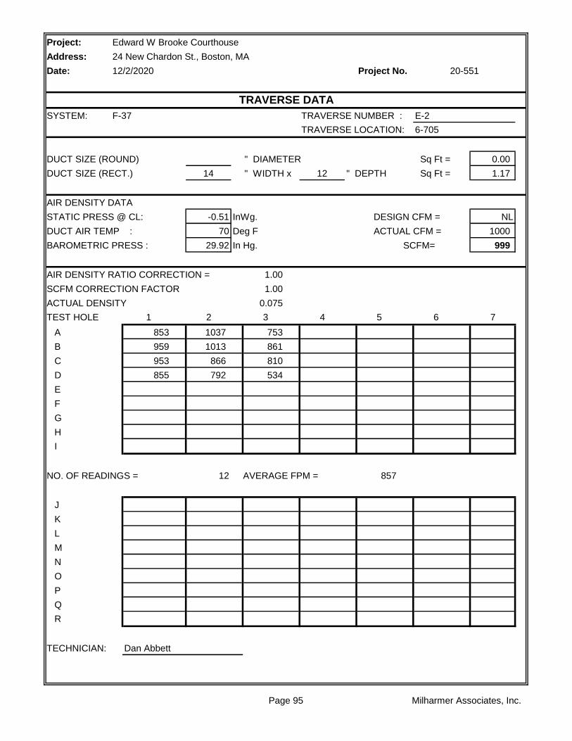
Project:
Address:
Date: Project No.
SYSTEM: F-37 TRAVERSE NUMBER : E-2
TRAVERSE LOCATION: 6-705
DUCT SIZE (ROUND) " DIAMETER Sq Ft = 0.00
DUCT SIZE (RECT.) 14 " WIDTH x 12 " DEPTH Sq Ft = 1.17
AIR DENSITY DATA
STATIC PRESS @ CL: -0.51 InWg. DESIGN CFM = NL
DUCT AIR TEMP : 70 Deg F ACTUAL CFM = 1000
BAROMETRIC PRESS : 29.92 In Hg. SCFM= 999
AIR DENSITY RATIO CORRECTION = 1.00
SCFM CORRECTION FACTOR 1.00
ACTUAL DENSITY 0.075
TEST HOLE 1 2 3 4 5 6 7
A 853 1037 753
B 959 1013 861
C 953 866 810
D 855 792 534
E
F
G
H
I
NO. OF READINGS = 12 AVERAGE FPM = 857
J
K
L
M
N
O
P
Q
R
TECHNICIAN: Dan Abbett
Edward W Brooke Courthouse
24 New Chardon St., Boston, MA
12/2/2020 20-551
TRAVERSE DATA
Page 95 Milharmer Associates, Inc.
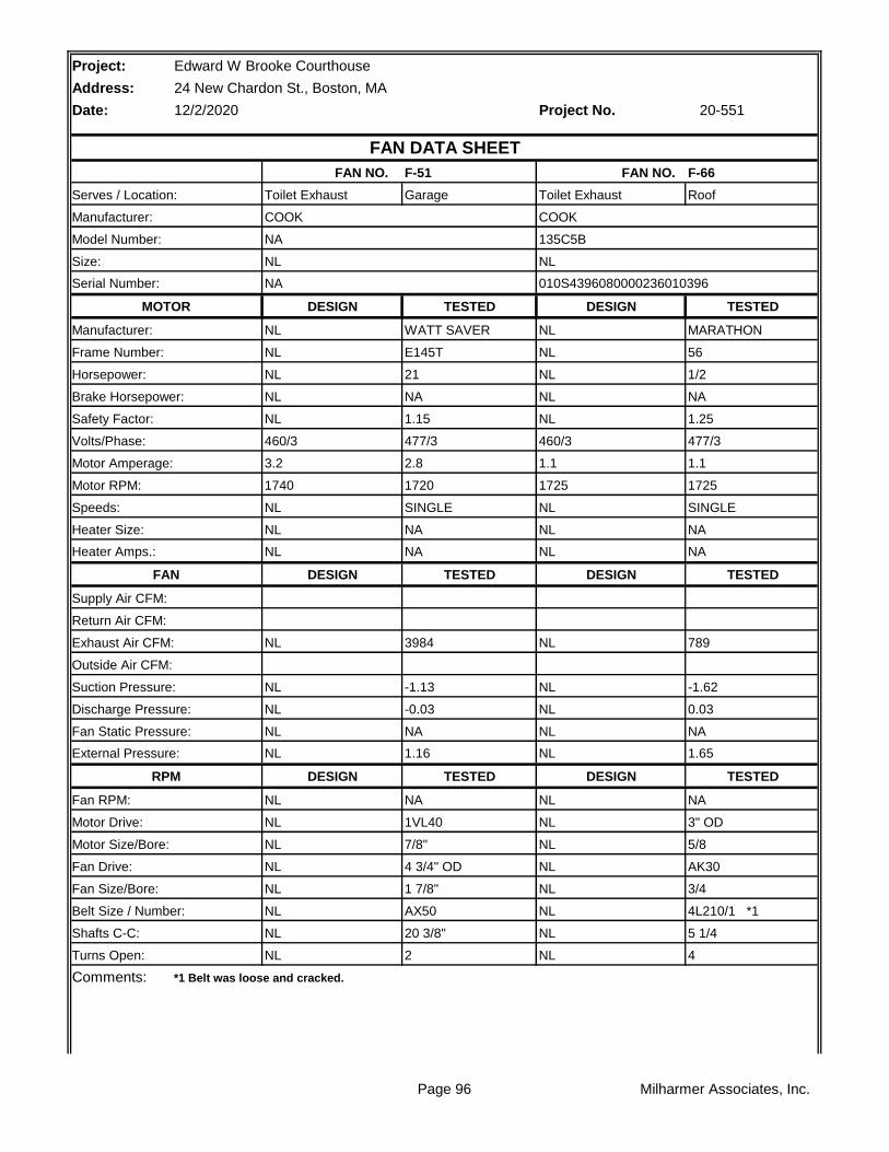
Project: Edward W Brooke Courthouse
Address: 24 New Chardon St., Boston, MA
Date: 12/2/2020 Project No.
F-51 F-66
Garage Roof
TESTED TESTED
WATT SAVER MARATHON
E145T 56
21 1/2
NA NA
1.15 1.25
477/3 477/3
2.8 1.1
1720 1725
SINGLE SINGLE
NA NA
NA NA
TESTED TESTED
3984 789
-1.13 -1.62
-0.03 0.03
NA NA
1.16 1.65
TESTED TESTED
NA NA
1VL40 3" OD
7/8" 5/8
4 3/4" OD AK30
1 7/8" 3/4
AX50 4L210/1 *1
20 3/8" 5 1/4
2 4
Comments:
Turns Open: NL NL
*1 Belt was loose and cracked.
Belt Size / Number: NL NL
Shafts C-C: NL NL
Fan Drive: NL NL
Fan Size/Bore: NL NL
Motor Drive: NL NL
Motor Size/Bore: NL NL
RPM DESIGN DESIGN
Fan RPM: NL NL
Fan Static Pressure: NL NL
External Pressure: NL NL
Suction Pressure: NL NL
Discharge Pressure: NL NL
Exhaust Air CFM: NL NL
Outside Air CFM:
Supply Air CFM:
Return Air CFM:
Heater Amps.: NL NL
FAN DESIGN DESIGN
Speeds: NL NL
Heater Size: NL NL
Motor Amperage: 3.2 1.1
Motor RPM: 1740 1725
Safety Factor: NL NL
Volts/Phase: 460/3 460/3
Horsepower: NL NL
Brake Horsepower: NL NL
Manufacturer: NL NL
Frame Number: NL NL
Serial Number: NA 010S4396080000236010396
MOTOR DESIGN DESIGN
Size: NL NL
Serves / Location: Toilet Exhaust Toilet Exhaust
Manufacturer: COOK COOK
20-551
FAN DATA SHEET
FAN NO. FAN NO.
Model Number: NA 135C5B
Page 96 Milharmer Associates, Inc.

Page 97 Milharmer Associates, Inc.
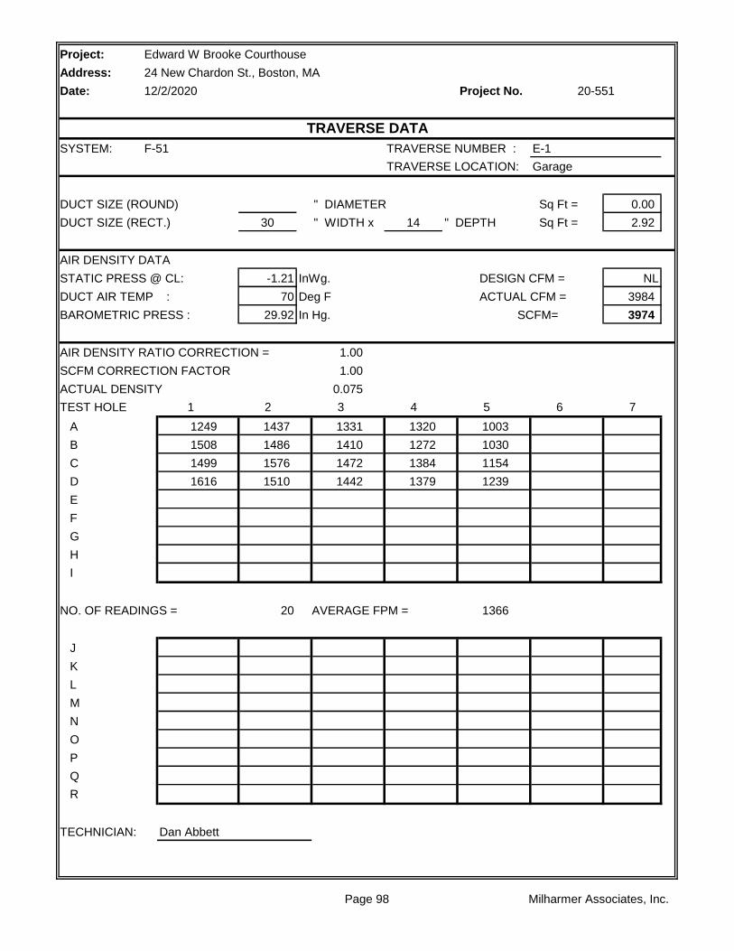
Project:
Address:
Date: Project No.
SYSTEM: F-51 TRAVERSE NUMBER : E-1
TRAVERSE LOCATION: Garage
DUCT SIZE (ROUND) " DIAMETER Sq Ft = 0.00
DUCT SIZE (RECT.) 30 " WIDTH x 14 " DEPTH Sq Ft = 2.92
AIR DENSITY DATA
STATIC PRESS @ CL: -1.21 InWg. DESIGN CFM = NL
DUCT AIR TEMP : 70 Deg F ACTUAL CFM = 3984
BAROMETRIC PRESS : 29.92 In Hg. SCFM= 3974
AIR DENSITY RATIO CORRECTION = 1.00
SCFM CORRECTION FACTOR 1.00
ACTUAL DENSITY 0.075
TEST HOLE 1 2 3 4 5 6 7
A 1249 1437 1331 1320 1003
B 1508 1486 1410 1272 1030
C 1499 1576 1472 1384 1154
D 1616 1510 1442 1379 1239
E
F
G
H
I
NO. OF READINGS = 20 AVERAGE FPM = 1366
J
K
L
M
N
O
P
Q
R
TECHNICIAN: Dan Abbett
Edward W Brooke Courthouse
24 New Chardon St., Boston, MA
12/2/2020 20-551
TRAVERSE DATA
Page 98 Milharmer Associates, Inc.

Project:
Address:
Date: Project No.
SYSTEM: F-66 TRAVERSE NUMBER : E-1
TRAVERSE LOCATION: 6th Fl. Stair 5
DUCT SIZE (ROUND) " DIAMETER Sq Ft = 0.00
DUCT SIZE (RECT.) 27 " WIDTH x 10 " DEPTH Sq Ft = 2.57
AIR DENSITY DATA
STATIC PRESS @ CL: -1.62 InWg. DESIGN CFM = NL
DUCT AIR TEMP : 70 Deg F ACTUAL CFM = 789
BAROMETRIC PRESS : 29.92 In Hg. SCFM= 786
AIR DENSITY RATIO CORRECTION = 1.00
SCFM CORRECTION FACTOR 1.00
ACTUAL DENSITY 0.075
TEST HOLE 1 2 3 4 5 6 7
A 276 295 312 287 282
B 324 343 318 312 311
C 331 338 325 322 229
D
E
F
G
H
I
NO. OF READINGS = 15 AVERAGE FPM = 307
J
K
L
M
N
O
P
Q
R
TECHNICIAN: Dan Abbett
Edward W Brooke Courthouse
24 New Chardon St., Boston, MA
12/2/2020 20-551
TRAVERSE DATA
Page 99 Milharmer Associates, Inc.