eds 05-2011 air circuit breaker protection...
TRANSCRIPT

Document Number: EDS 05-2011
Version: 5.0
Date: 11/06/2018
TH
IS IS
AN
UN
CO
NT
RO
LL
ED
DO
CU
ME
NT
, T
HE
RE
AD
ER
MU
ST
CO
NF
IRM
IT
S V
AL
IDIT
Y B
EF
OR
E U
SE
ENGINEERING DESIGN STANDARD
EDS 05-2011
AIR CIRCUIT BREAKER PROTECTION SETTINGS
Network(s): EPN, LPN, SPN
Summary: This standard details the current and previous protection settings used on LV air circuit breakers used on the EPN, LPN and SPN networks.
Author: Jesse Garcia Date: 11/06/2018
Approver: Paul Williams Date: 06/08/2018
This document forms part of the Company's Integrated Business System and its requirements are mandatory throughout UK Power Networks. Departure from these requirements may only be taken with the written approval of the Director of Asset Management. If you have any queries about this document please contact the author or owner of the current version.
Circulation
UK Power Networks External
☒ Asset Management ☒ UK Power Networks Services
☐ Capital Programme ☒ Contractors
☒ Connections ☒ ICPs/IDNOs
☐ Health & Safety ☐ Meter Operators
☐ Legal ☒ G81 Website
☒ Network Operations
☐ Procurement
☐ Strategy & Regulation
☒ Technical Training

Air Circuit Breaker Protection Settings Document Number: EDS 05-2011
Version: 5.0
Date: 11/06/2018
© UK Power Networks 2018 All rights reserved 2 of 24
Revision Record
Version 5.0 Review Date 06/08/2023
Date 20/06/2018 Author Jesse Garcia
Reason for update: Periodic review, change of type of HV TLF fuses available.
What has changed: Concentrated all settings on a single table. Updated protection curve diagrams. Removed Appendix C.
Version 4.0 Review Date 03/06/2018
Date 13/05/2015 Author Jesse Garcia
Reason for update: Periodic review
What has changed – Section 3.1 updated to include 10A tagged TLF, Section 3.2 title updated to include EPN and SPN, Sections 3.2.2, 3.2.3 and 3.2.4 - tables referencing RMU TLF Fuse (A) updated, Section 5 reference list updated.
Version 3.0 Review Date 24/04/2015
Date 19/03/2012 Author Damien Delea
Reclassification of document from EI 05-2011. Document reviewed. All protection settings revised, customer discrimination and grading curves added.
Version 2.0 Review Date
Date 07/08/2007 Author D J Collis
Update to current protection settings – Section 6.
Version 1.1 Review Date
Date 16/07/2007 Author D J Collis
Section 6.1.1 Iinst = 6 changed to Iinst = 15.
Section 6.1.2 Iinst = 8 changed to Iinst = 15.
Version 1.0 Review Date
Date 12/06/2005 Author D J Collis
Original.
Air Circuit Breaker Protection Settings Document Number: EDS 05-2011
Version: 5.0
Date: 11/06/2018
© UK Power Networks 2018 All rights reserved 3 of 24
Contents
1 Introduction ............................................................................................................. 5
2 Scope ....................................................................................................................... 5
3 Glossary and Abbreviations ................................................................................... 5
4 Protection Settings for New ACBs ......................................................................... 5
4.1 General ..................................................................................................................... 5
4.2 ACB protection settings for all Micrologic 5.0. ............................................................ 8
4.3 Reverse Power Relays .............................................................................................. 9
5 Protection Settings for Legacy ACBs .................................................................... 9
5.1 Schneider Electric NW20H1 (2007-2011) .................................................................. 9
5.2 Merlin Gerin NW25H1 and NT16H1 (EPN 2003 to 2007) ........................................ 10
5.3 Merlin Gerin NW16H1 and NW20H1 (LPN 2003 to 2007)........................................ 10
5.4 Merlin Gerin NS1250 (EPN 2003 onwards) ............................................................. 11
5.5 Merlin Gerin M16H1 (EPN 1993 to 2003) ................................................................ 11
5.6 Merlin Gerin M25 (EPN 1993 to 2003) ..................................................................... 12
5.7 Merlin Gerin M16 and M25 (EPN 1991 to 1993) ...................................................... 12
5.8 Merlin Gerin M16 and M25 (EPN 1991 to 1993) ...................................................... 13
5.9 Merlin Gerin C1250N and C1251N (EPN 1988 to 1992) .......................................... 13
5.10 Dorman Smith 600A and 1250A MCCB (before 1988) ............................................. 14
6 References ............................................................................................................. 14
6.1 UK Power Networks Standards ............................................................................... 14
Appendix A – Protection Settings Explained .................................................................. 15
A.1 Schneider Electric Micrologic Protection Modules ................................................... 15
A.2 Merlin Gerin (or Schneider Electric) STR38ST Trip Unit Settings ............................ 15
A.3 Dorman Smith Trip Units ......................................................................................... 15
Appendix B - AMTECH Protection Curves ...................................................................... 16
B.1 11kV 500kVA Transformer ACB 1600A rating ......................................................... 16
B.2 11kV 500kVA Transformer ACB 2000A rating ......................................................... 17
B.3 11kV 750kVA Transformer ACB 1600A rating ......................................................... 18
B.4 11kV 750kVA Transformer ACB 2000A rating ......................................................... 19
B.5 11kV 800kVA Transformer ACB 1600A rating ......................................................... 20
B.6 11kV 800kVA Transformer ACB 2000A rating ......................................................... 21
B.7 11kV 1000kVA Transformer ACB 1600A rating ....................................................... 22
B.8 11kV 1500kVA Transformer ACB 2500A rating ....................................................... 23
B.9 11kV 1500kVA Transformer ACB 2500A rating ....................................................... 24

Air Circuit Breaker Protection Settings Document Number: EDS 05-2011
Version: 5.0
Date: 11/06/2018
© UK Power Networks 2018 All rights reserved 4 of 24
Figures
Figure 4-1 - Large LV supply from network feeding substation .............................................. 6
Tables
Table 1 ACB protection settings ............................................................................................ 8

Air Circuit Breaker Protection Settings Document Number: EDS 05-2011
Version: 5.0
Date: 11/06/2018
© UK Power Networks 2018 All rights reserved 5 of 24
1 Introduction
This standard details the protection settings for LV Air Circuit Breakers (ACB) and includes settings for new and legacy ACBs.
This standard has been updated to meet the requirements for large customer LV supplies detailed in UK Power Networks EDS 08-2100 LV Customer Supplies.
2 Scope
This standard applies to all ACBs on UK Power Networks EPN, LPN and SPN networks.
3 Glossary and Abbreviations
Term Definition
ACB Air Circuit Breakers
TLF Time Fuse Link
TS&S Technical Sourcing and Standards
RMU Ring Main Unit
LV Low Voltage
HV High Voltage
UK Power Networks UK Power Networks (Operations) Ltd consists of three electricity distribution networks:
Eastern Power Networks plc (EPN).
London Power Network plc (LPN).
South Eastern Power Networks plc (SPN).
4 Protection Settings for New ACBs
4.1 General
A common range of ACBs are available and are used to provide large supplies to LV customers or supply the LPN interconnected network (with reverse power relays). Refer to UK Power Networks EDS 08-0803 for further information on their application.
The approved ranges of ACBs are supplied by Schneider Electric and are fitted with a Micrologic 5.0A protection module to provide overcurrent protection. Refer to the relevant Engineering Approval Standard for the current range of approved ACBs.
The ACB protection settings in section 4.2 have been selected to provide the best discrimination between the network LV distribution board on which there are large BS88 J type fuses to customers.
The protection settings for various ACBs and various sizes of transformer to discriminate with a 15A or 12.5A tagged TLF, used for transformer HV overcurrent protection, are given in the sections that follow. The tagged type TLFs shall be used in conjunction with LV ACBs to allow for discrimination in settings. An explanation of the various settings is given in appendix A and the associated AMTECH curves are included in Appendix B.
Air Circuit Breaker Protection Settings Document Number: EDS 05-2011
Version: 5.0
Date: 11/06/2018
© UK Power Networks 2018 All rights reserved 6 of 24
If the standard settings are not suitable due to network variations please contact UK Power Networks Asset Management for site specific settings.
A network variation example is when a customer has an ACB to protect their site. The customer shall attempt to grade with UK Power Networks standard settings, however if they have difficulties they might request a variation in settings. This case shall be investigated by the Asset Management – Technical Standards protection engineers and only with their permission variation from standard settings will occur.
Note:
The Micrologic protection module is pre-set with the protection settings for a 750/800/1000kVA transformer by the supplier.
The Micrologic 6.0A is not suitable for use on the LPN network and care should be taken when it is used on the other networks as the earth fault settings may not provide sufficient discrimination or co-ordination with downstream fusing.
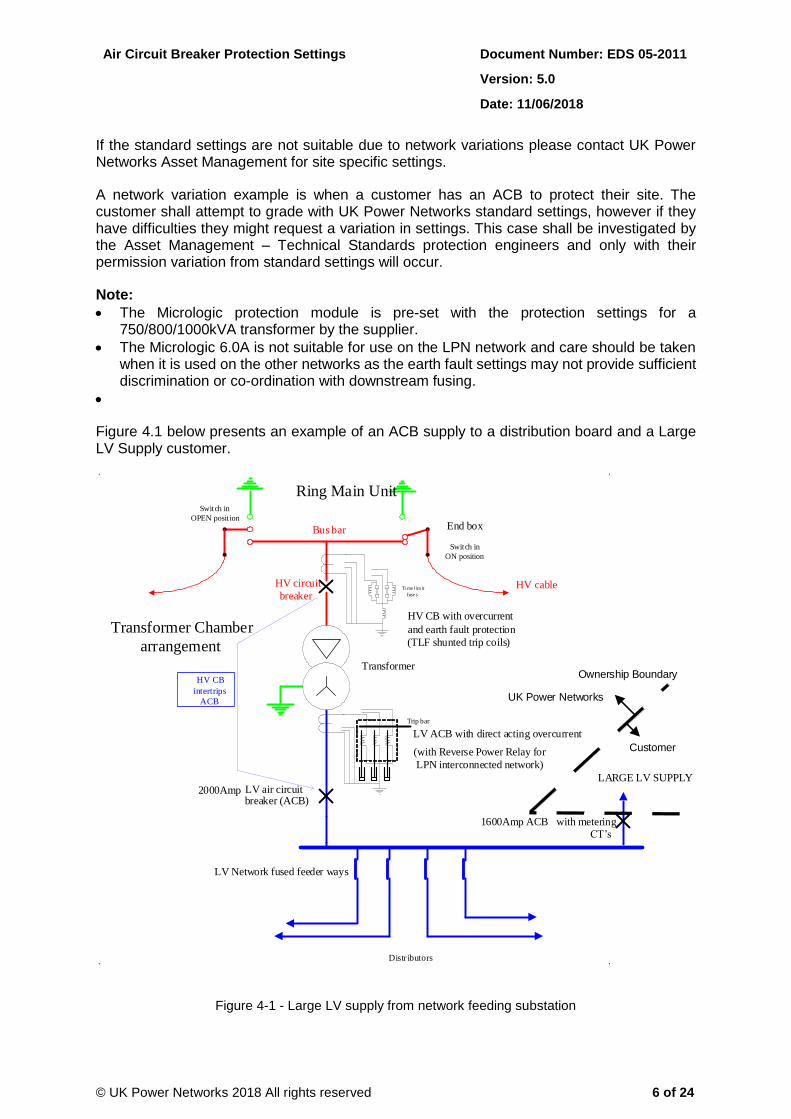
Figure 4.1 below presents an example of an ACB supply to a distribution board and a Large LV Supply customer.
Bus bar
HV cable
End box
Switch in ON position
HV circuit breaker
LV air circuit breaker (ACB)
Switch in OPEN posit ion
Time l im it fuse s
Transformer
Distr ibutors
Transformer Chamber
arrangement
HV CB intertrips
ACB
LV Network fused feeder ways
HV CB with overcurrent and earth fault protection (TLF shunted trip coils)
LV ACB with direct acting overcurrent (with Reverse Power Relay for
LPN interconnected network)
Ring Main Unit
Trip bar
LARGE LV SUPPLY
1600Amp ACB
with metering CT’s
Customer
UK Power Networks
Ownership Boundary
2000Amp
Figure 4-1 - Large LV supply from network feeding substation

Air Circuit Breaker Protection Settings Document Number: EDS 05-2011
Version: 5.0
Date: 11/06/2018
© UK Power Networks 2018 All rights reserved 7 of 24
Due to the obsolescence of glass barrel type fuses and the adoption of XF TLF fuses, time grading on the 6.6kV network has become difficult and the possibility of ACB protection operating faster than an LV Fuse is larger. As such it is important for operational staff to follow the instructions on HSS 40 017 when re-energizing devices. There is an ongoing investigation by the Asset Management TS&S team to adopt RMUs where the HV transformer protection is provided by an IDMT capable relay instead of an XF TLF fuse for secondary substations that have ACBs. If the proposal is adopted, this document shall be updated.

Air Circuit Breaker Protection Settings Document Number: EDS 05-2011
Version: 5.0
Date: 11/06/2018
© UK Power Networks 2018 All rights reserved 8 of 24
4.2 ACB protection settings for all Micrologic 5.0.
Note: The settings below are applicable to all Micrologic 5.0 ACBs, protection modules, including large single service customers.
Table 1 ACB protection settings
Syste
m V
olt
ag
e (
kV
)
Tra
nsfo
rme
r (k
VA
)
AC
B R
ati
ng
(A
)
RM
U C
T R
ati
o
RM
U T
LF
Fu
se (
A)
AC
B P
rote
cti
on
Mo
du
le
Ir tr Isd tsd
(+i2t) Iinst
Larg
est
po
ssib
le L
V f
use
(A
)
6.6
500 1600
100/5
15.0
Mic
rolo
gic
5.0
A
0.70
4 4
0.2 6 400
500 2000 15.0 0.60 0.2 6 400
750 1600 15.0 0.95 0.1 8 500
750 2000 15.0 0.80 0.1 6 500
800 1600 15.0 1.00 0.1 8 500
800 2000 15.0 0.80 0.1 6 500
1000 1600 15.0 0.95 0.1 8 500
1000 2000 15.0 0.80 0.1 6 500
11
500 1600 12.5 0.70 0.2 10 400
500 2000 12.5 0.70 0.2 8 400
750 1600 15.0 0.80 0.2 8 500
750 2000 15.0 0.80 0.2 10 500
800 1600 15.0 1.00 0.2 12 500
800 2000 15.0 0.80 0.2 10 500
1000 1600 15.0 1.00 0.2 12 500
1000 2000 15.0 0.80 0.2 10 500
1500 2500 15.0 0.80 0.2 8 N/A

Air Circuit Breaker Protection Settings Document Number: EDS 05-2011
Version: 5.0
Date: 11/06/2018
© UK Power Networks 2018 All rights reserved 9 of 24
4.3 Reverse Power Relays
On the LV interconnected network in the LPN area, reverse power relays are used to detect reverse power flow caused by a fault on the HV side of the transformer and trip the ACB to prevent back feed from the LV side. Over-current protection is not required on these ACBs.
There are two types of relay used:
The English Electric CAG with a PCD directional element;
The Reyrolle TGG relay.
Both relays have fixed settings that are set to trip at roughly three times the LV current with the secondary set at 10A.
5 Protection Settings for Legacy ACBs
This section details the protection settings for legacy ACBs used on the EPN, LPN and SPN networks between 1st July 2007 and 31st December 2011.
If the HV TLF fuses are replaced with new ones on an ACB with Micrologic 5.0 protection then the settings shall be changed to the ones presented I previously in chapter 4.2. If the HV TLF fuses are replaced with new ones on an ACB with Micrologic 6.0, please contact UK Power Networks Asset Management for site specific settings.
Note: ACBs were introduced in SPN in 2007.
5.1 Schneider Electric NW20H1 (2007-2011)
ACB NW20H1
System Voltage (kV) 11 11 6.6
Transformer (kVA) 1000, 800, 750 500
RMU CT Ratio 100/5 50/5
RMU TLF Fuse (A) 15 15
ACB Protection Module Micrologic 6.0A/6.0P Micrologic 6.0A/6.0P Micrologic 6.0A/6.0P
ACB Protection Settings Ir = 1 Ir = 0.6 Ir = 0.7
tr = 4 tr = 4 tr = 4
Isd = 4 Isd = 4 Isd = 4
tsd = 0.1+ I2t tsd = 0.1+ I2t tsd = 0.1+ I2t
Iinst = 15 Iinst = 15 Iinst = 15
Ig = Ig = Ig =
tg = tg = tg =
Air Circuit Breaker Protection Settings Document Number: EDS 05-2011
Version: 5.0
Date: 11/06/2018
© UK Power Networks 2018 All rights reserved 10 of 24
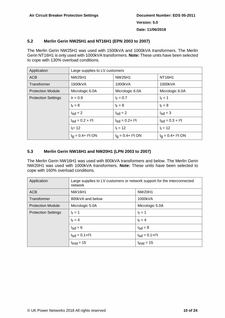
5.2 Merlin Gerin NW25H1 and NT16H1 (EPN 2003 to 2007)
The Merlin Gerin NW25H1 was used with 1500kVA and 1000kVA transformers. The Merlin Gerin NT16H1 is only used with 1000kVA transformers. Note: These units have been selected to cope with 130% overload conditions.
Application Large supplies to LV customers
ACB NW25H1 NW25H1 NT16H1
Transformer 1500kVA 1000kVA 1000kVA
Protection Module Micrologic 6.0A Micrologic 6.0A Micrologic 6.0A
Protection Settings Ir = 0.9 Ir = 0.7 Ir = 1
tr = 8 tr = 8 tr = 8
Isd = 2 Isd = 2 Isd = 3
tsd = 0.2 + I2t tsd = 0.2+ I2t tsd = 0.3 + I2t
Ii= 12 Ii = 12 Ii = 12
tg = 0.4+ I2t ON tg = 0.4+ I2t ON tg = 0.4+ I2t ON
5.3 Merlin Gerin NW16H1 and NW20H1 (LPN 2003 to 2007)
The Merlin Gerin NW16H1 was used with 800kVA transformers and below. The Merlin Gerin NW20H1 was used with 1000kVA transformers. Note: These units have been selected to cope with 160% overload conditions.
Application Large supplies to LV customers or network support for the interconnected network
ACB NW16H1 NW20H1
Transformer 800kVA and below 1000kVA
Protection Module Micrologic 5.0A Micrologic 5.0A
Protection Settings Ir = 1 Ir = 1
tr = 4 tr = 4
Isd = 6 Isd = 8
tsd = 0.1+I2t tsd = 0.1+I2t
Iinst = 15 Iinst = 15

Air Circuit Breaker Protection Settings Document Number: EDS 05-2011
Version: 5.0
Date: 11/06/2018
© UK Power Networks 2018 All rights reserved 11 of 24
5.4 Merlin Gerin NS1250 (EPN 2003 onwards)
The Merlin Gerin NS1250 was used with 500kVA and 700 kVA transformers. Note: This unit has been selected to cope with 130% overload conditions.
Application Large supplies to LV customers
ACB NS1250 NS1250
Transformer 500kVA 700kVA
Protection Module Micrologic 5.0A Micrologic 5.0A
Protection Settings Ir = 0.9 Ir = 1
tr = 8 tr = 8
Isd = 2.5 Isd = 5
tsd = 0.3 + I2t tsd = 0.3 + I2t
Ii = 15 Ii = 15
5.5 Merlin Gerin M16H1 (EPN 1993 to 2003)
The Merlin Gerin M16H1 was used with 1000kVA transformers. Note: This unit has been selected to cope with 130% overload conditions.
Application Large supplies to LV customers
ACB M16H1
Transformer 1000kVA
Protection Module STR38ST
Protection Settings Io = 1
Ir = 1
Im = 3
tm = 0.3 + I2t ON
Ii = max/ON (any position in shaded area)
Ih = 500
th = 0.4 + I2t ON
Minimum tripping current 1680A
Note:
Current in excess of the minimum tripping currents may trip the circuit-breaker after 200s.
The STR38ST trip units used on Masterpact ACBs from 1993 may be unstable and may give nuisance tripping on low loads if Ih is set to less than 500A.
Air Circuit Breaker Protection Settings Document Number: EDS 05-2011
Version: 5.0
Date: 11/06/2018
© UK Power Networks 2018 All rights reserved 12 of 24
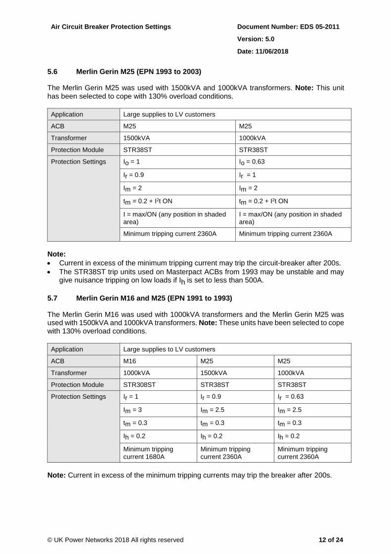
5.6 Merlin Gerin M25 (EPN 1993 to 2003)
The Merlin Gerin M25 was used with 1500kVA and 1000kVA transformers. Note: This unit has been selected to cope with 130% overload conditions.
Application Large supplies to LV customers
ACB M25 M25
Transformer 1500kVA 1000kVA
Protection Module STR38ST STR38ST
Protection Settings Io = 1 Io = 0.63
Ir = 0.9 Ir = 1
Im = 2 Im = 2
tm = 0.2 + I2t ON tm = 0.2 + I2t ON
I = max/ON (any position in shaded area)
I = max/ON (any position in shaded area)
Minimum tripping current 2360A Minimum tripping current 2360A
Note:
Current in excess of the minimum tripping current may trip the circuit-breaker after 200s.
The STR38ST trip units used on Masterpact ACBs from 1993 may be unstable and may give nuisance tripping on low loads if Ih is set to less than 500A.
5.7 Merlin Gerin M16 and M25 (EPN 1991 to 1993)
The Merlin Gerin M16 was used with 1000kVA transformers and the Merlin Gerin M25 was used with 1500kVA and 1000kVA transformers. Note: These units have been selected to cope with 130% overload conditions.
Application Large supplies to LV customers
ACB M16 M25 M25
Transformer 1000kVA 1500kVA 1000kVA
Protection Module STR308ST STR38ST STR38ST
Protection Settings Ir = 1 Ir = 0.9 Ir = 0.63
Im = 3 Im = 2.5 Im = 2.5
tm = 0.3 tm = 0.3 tm = 0.3
Ih = 0.2 Ih = 0.2 Ih = 0.2
Minimum tripping current 1680A
Minimum tripping current 2360A
Minimum tripping current 2360A
Note: Current in excess of the minimum tripping currents may trip the breaker after 200s.

Air Circuit Breaker Protection Settings Document Number: EDS 05-2011
Version: 5.0
Date: 11/06/2018
© UK Power Networks 2018 All rights reserved 13 of 24
5.8 Merlin Gerin M16 and M25 (EPN 1991 to 1993)
The Merlin Gerin M16 was used with 1000kVA transformers and the Merlin Gerin M25 was used with 1500kVA and 1000kVA transformers. Note: These units have been selected to cope with 130% overload conditions.
Application Large supplies to LV customers
ACB M16 M25 M25
Transformer 1000kVA 1500kVA 1000kVA
Protection Module STR308ST STR38ST STR38ST
Protection Settings Ir = 1 Ir = 0.9 Ir = 0.63
Im = 3 Im = 2.5 Im = 2.5
tm = 0.3 tm = 0.3 tm = 0.3
Ih = 0.2 Ih = 0.2 Ih = 0.2
Minimum tripping current 1680A
Minimum tripping current 2360A
Minimum tripping current 2360A
Note: Current in excess of the minimum tripping currents may trip the breaker after 200s.
5.9 Merlin Gerin C1250N and C1251N (EPN 1988 to 1992)
The Merlin Gerin C1250N and C1251N were used with 500kVA and 700kVA transformers. Note: These units have been selected to cope with 130% overload conditions.
Application Large supplies to LV customers
ACB C1250N C1250N C1251N C1251N
Transformer 500kVA 700kVA 500kVA 700kVA
Protection Settings Io = 1 Io = 1
Protection Settings Ir = 0.8 Ir = 1 Ir = 0.9 Ir = 1
Im = 4 Im = 5 Im = 2.5 Im = 6
tm = 0.3 tm = 0.3 + I2t
ON
tm = 0.3 + I2t ON tm = 0.3

Air Circuit Breaker Protection Settings Document Number: EDS 05-2011
Version: 5.0
Date: 11/06/2018
© UK Power Networks 2018 All rights reserved 14 of 24
5.10 Dorman Smith 600A and 1250A MCCB (before 1988)
The Dorman Smith 600A and 1200A MCCBs were used with 500kVA and 700kVA transformers respectively.
Application Large supplies to LV customers
ACB 600A 1250A
Transformer 500kVA 700kVA
Protection Module 600A Tripping Unit Type A 1250A Tripping Unit Type B
Thermal Over Load Setting No. 5 No. 4
Instantaneous Magnetic Release High High
6 References
6.1 UK Power Networks Standards
EDS 08-2100 LV Customer Supplies
HSS 40 017 Low Voltage Re-Energising Devices

Air Circuit Breaker Protection Settings Document Number: EDS 05-2011
Version: 5.0
Date: 11/06/2018
© UK Power Networks 2018 All rights reserved 15 of 24
Appendix A – Protection Settings Explained
This appendix provides a brief explanation of the protection settings used on the various protection modules.
A.1 Schneider Electric Micrologic Protection Modules
Protection Element
Description Function
Ir Long time current setting Adjusts pickup current
tr Long time tripping delay Adjusts time to trip the long time current setting
Isd Short time pickup (multiple of Ir) Adjusts current setting of intermediate vertical lines
tsd Short time tripping delay Adjusts time setting of high current trip (2nd horizontal/ slope from left)
Iinst or Ii Instantaneous pickup Sets high current instantaneous pickup
Ig Earth fault pickup Adjusts earth fault current
tg Earth fault time delay Adjusts earth fault time delay
A.2 Merlin Gerin (or Schneider Electric) STR38ST Trip Unit Settings
Protection Element
Description Function
Io Long time current setting Provides a wider range of pickup current
Ir Long time current setting (on STR38ST or C1251N = Io x Ir)
Adjusts pickup current
Im Short time pickup (multiple of Ir) Adjusts current setting of intermediate vertical lines
tm Short time tripping delay Adjusts time setting of high current trip (2nd horizontal/ slope from left)
Ii Instantaneous pickup (STR38ST has 2 settings only - MAX and OFF)
Sets high current instantaneous pickup
Ih Earth fault pickup Adjusts earth fault current
th Earth fault time delay Adjusts earth fault time delay
A.3 Dorman Smith Trip Units
The trip unit size is not visible unless the MCCB (Moulded Case Circuit Breaker) front panel is removed. Note: That the 600A trip unit is rated at 700A when fitted in the standard (1250A) MCCB and cubicle.

Air Circuit Breaker Protection Settings Document Number: EDS 05-2011
Version: 5.0
Date: 11/06/2018
© UK Power Networks 2018 All rights reserved 16 of 24
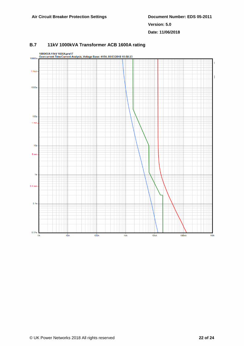
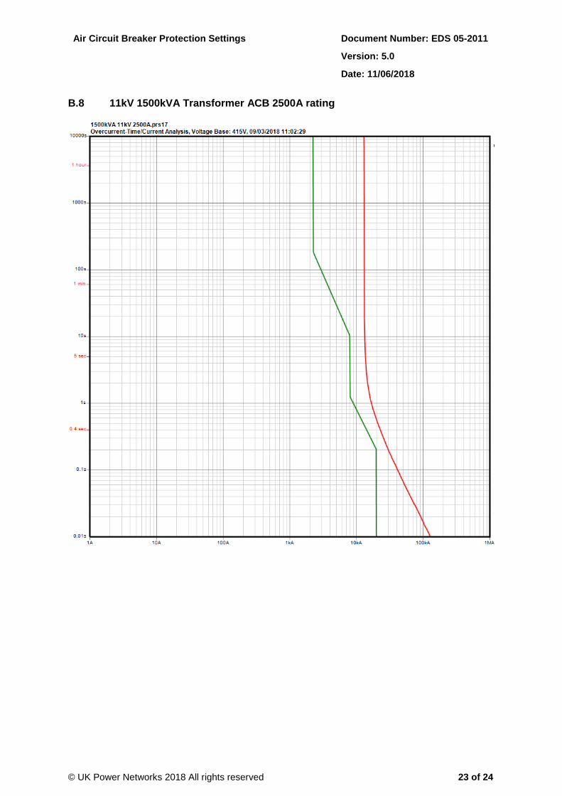
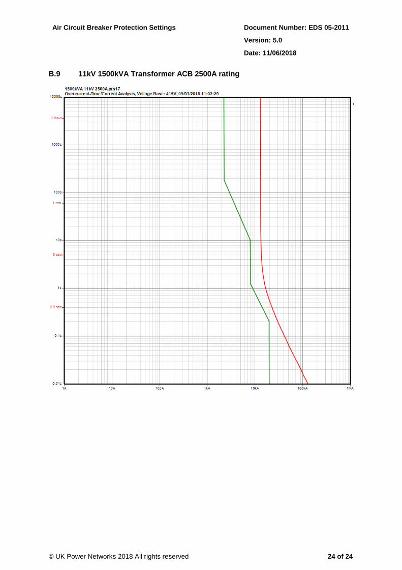
Appendix B - AMTECH Protection Curves
This appendix contains the AMTECH plots for each of the settings in Section 4. Key:
Top (red) curve – ring main unit (HV AC Series Tripping) tagged TLF fuse.
Middle (green) (green or blue in B10) curve – ACB.
Bottom (blue) (orange in B10) curve – 400A BS88 J type supply fuse.
B.1 11kV 500kVA Transformer ACB 1600A rating

Air Circuit Breaker Protection Settings Document Number: EDS 05-2011
Version: 5.0
Date: 11/06/2018
© UK Power Networks 2018 All rights reserved 17 of 24
B.2 11kV 500kVA Transformer ACB 2000A rating

Air Circuit Breaker Protection Settings Document Number: EDS 05-2011
Version: 5.0
Date: 11/06/2018
© UK Power Networks 2018 All rights reserved 18 of 24
B.3 11kV 750kVA Transformer ACB 1600A rating

Air Circuit Breaker Protection Settings Document Number: EDS 05-2011
Version: 5.0
Date: 11/06/2018
© UK Power Networks 2018 All rights reserved 19 of 24
B.4 11kV 750kVA Transformer ACB 2000A rating

Air Circuit Breaker Protection Settings Document Number: EDS 05-2011
Version: 5.0
Date: 11/06/2018
© UK Power Networks 2018 All rights reserved 20 of 24
B.5 11kV 800kVA Transformer ACB 1600A rating

Air Circuit Breaker Protection Settings Document Number: EDS 05-2011
Version: 5.0
Date: 11/06/2018
© UK Power Networks 2018 All rights reserved 21 of 24
B.6 11kV 800kVA Transformer ACB 2000A rating
Air Circuit Breaker Protection Settings Document Number: EDS 05-2011
Version: 5.0
Date: 11/06/2018
© UK Power Networks 2018 All rights reserved 22 of 24
B.7 11kV 1000kVA Transformer ACB 1600A rating
Air Circuit Breaker Protection Settings Document Number: EDS 05-2011
Version: 5.0
Date: 11/06/2018
© UK Power Networks 2018 All rights reserved 23 of 24
B.8 11kV 1500kVA Transformer ACB 2500A rating
Air Circuit Breaker Protection Settings Document Number: EDS 05-2011
Version: 5.0
Date: 11/06/2018
© UK Power Networks 2018 All rights reserved 24 of 24
B.9 11kV 1500kVA Transformer ACB 2500A rating