edf high voltage cable insulation testing policy
DESCRIPTION
fgTRANSCRIPT
Document Number: EI 09-0001
Version: 5.0
Date: 10/03/2009
1 of 14
THIS
IS A
N U
NC
ON
TRO
LLED
DO
CU
MEN
T, T
HE
REA
DER
MU
ST C
ON
FIR
M IT
S VA
LID
ITY
BEF
OR
E U
SE
ENGINEERING INSTRUCTION
EI 09-0001
HIGH VOLTAGE INSULATION TESTING POLICY
Network(s): EPN, LPN, SPN
Summary: This engineering instruction details the policy for the on-site insulation testing of new and existing high voltage cables, switchgear and transformers.
Originator: Paul Williams Date: 10/03/2009
Approved By:
Colin Gardner Approved Date: 28/04/2009
Review Date: 11/02/2011
This document forms part of the Company’s Integrated Business System and its requirements are mandatory throughout EDF Energy Networks Branch. Departure from these requirements may only be taken with the written approval of the Director of Capital Programme. If you have any queries about this document please contact the originator of the current issue.
Document History (The document history notes below are intended as a guide only and may not cover all of the changes. If you wish to make use of this document it should be read in full.)
Version Date Details Originator
5.0 10/03/2009 Revision to test voltage for 66 and 132kV cables
Paul Williams

Document Number: EI 09-0001
Version: 5.0
High Voltage Insulation Testing Policy
Date: 10/03/2009
2 of 14
Contents
1 Introduction ............................................................................................................. 4 2 Scope ....................................................................................................................... 4 3 References............................................................................................................... 4 4 Testing ..................................................................................................................... 5 4.1 General ..................................................................................................................... 5 4.2 New Apparatus.......................................................................................................... 5 4.3 Existing Apparatus..................................................................................................... 5 4.4 Test Application......................................................................................................... 5 4.5 Test Methods............................................................................................................. 6 5 Cable Testing........................................................................................................... 6 5.1 New and Existing Cables up to and including 33kV ................................................... 6 5.2 Acceptable IR Values ................................................................................................ 7 5.3 Cable Fault Location up to 33kV................................................................................ 7 5.4 Cable Over-sheath Tests – 11kV to 33kV Cables...................................................... 7 5.5 New and Existing Cables – 66kV and 132kV Oil and Gas Pressure Assisted
Cables ....................................................................................................................... 8 5.6 New and Existing Cables - 66kV and 132kV cables containing XLPE insulated
Cable......................................................................................................................... 8 5.7 Cable Fault Location – 66kV and 132kV.................................................................... 9 5.8 Cable Over-sheath Tests – 66kV and 132kV Cables ................................................. 9 5.9 Switchgear Associated with Cable Testing .............................................................. 10 6 Switchgear Testing................................................................................................ 10 6.1 Test Voltages .......................................................................................................... 10 6.1.1 New switchgear ....................................................................................................... 10 6.1.2 Existing switchgear.................................................................................................. 10 6.1.3 Application of test voltage........................................................................................ 11 6.2 Alternative Soak Test for 66kV and 132kV GIS Switchgear ..................................... 12 6.3 Air Insulated Bus Bars and Disconnectors............................................................... 12 7 Transformer Testing.............................................................................................. 12 7.1 Transformer Tails and Test Access ......................................................................... 13 8 Overhead Line Testing.......................................................................................... 14 9 Test Results........................................................................................................... 14

Document Number: EI 09-0001
Version: 5.0
High Voltage Insulation Testing Policy
Date: 10/03/2009
3 of 14
Tables
Table 1: Minimum test voltages for new and existing cables up to and including 33kV...... 6 Table 2: Maximum voltage levels for fault location for cable up to and including 33kV....... 7 Table 3: Cable over-sheath test voltages for cables up to 33kV ........................................ 8 Table 4: Minimum test voltages for new and existing fluid and gas filled 66kV and
132kV cables ....................................................................................................... 8 Table 5: Minimum test voltages for new 66kV and 132kV XLPE cables ............................ 9 Table 6: Minimum test voltages for 66kV and 132kV Cable System containing existing
sections of cable.................................................................................................. 9 Table 7: Maximum voltage levels for fault location for 66kV and 132kV Cable Systems.... 9 Table 8: Cable over-sheath test voltages for cables - 66kV and 132kV ........................... 10 Table 9: Test voltages for new extensible switchgear ...................................................... 11 Table 10: Test voltages for existing switchgear ................................................................. 11 Table 11: Test voltages for transformers ........................................................................... 13 Table 12: Maximum test voltages for transformers (for example where other equipment
is connected) ..................................................................................................... 13
Document Number: EI 09-0001
Version: 5.0
High Voltage Insulation Testing Policy
Date: 10/03/2009
4 of 14
1 Introduction This engineering instruction details the policy for the on-site insulation testing of high voltage cables, switchgear and transformers. The purpose of on-site insulation testing is to demonstrate that apparatus can be safely connected to the system. The testing regime detailed in this policy is designed to avoid unnecessary overstressing and to prolong the life of the apparatus. It should identify any gross defect, damage or earths left connected at a remote end. The testing regime is based on current practice from the relevant British and International standards together with current practice used on the three EDF Energy networks. Consideration has been given to safety of field staff, the availability of test equipment and the relative merits of ac, dc and very low frequency (VLF) ac testing. This policy supersedes the following documents: • EPN: EDM V12/S1/8 - Site Insulation Tests for High Voltage Equipment.
• LPN: E5-6-1 - Dielectric Testing.
• LPN: E5-6-1-1 - HV Dielectric Testing.
• SPN: EI 9-001-12 - Site Insulation Testing of Cables, Switchgear and Transformers.
• SPN: Site Testing & Commissioning Manual – 2.N3 - On-site Insulation Testing of Cables, Switchgear & Transformers.
2 Scope This policy applies to the insulation testing of cables, switchgear and transformers from 1000V to 132kV on the EPN, LPN, SPN and private networks and includes: • New apparatus before it is connected to the system for the first time.
• Existing apparatus after it has been modified, repaired or moved.
• Existing solid cable after it has been de-energised for an extended period.
• Cable fault locating.
• The testing of insulated cable sheaths.
• Overhead lines where insulation testing is not considered practicable.
This policy does not seek to provide condition monitoring information or partial discharge information.
3 References EDF Energy Distribution Safety Rules
EI 05-1001 Commissioning Policy
Document Number: EI 09-0001
Version: 5.0
High Voltage Insulation Testing Policy
Date: 10/03/2009
5 of 14
4 Testing
4.1 General
Testing shall be carried out: • After apparatus is installed (or re-installed) but before energisation for the first time.
• After work on the insulation of apparatus, but not normally after routine maintenance.
• After cable with solid insulation has been intentionally left de-energised for more than one month
For new and re-commissioned equipment the interval between testing and energisation from the system should be the minimum practicable: • Cables up to and including 11kV no more than 24 hours.
• Cable systems from 22kV and up to and including 132kV this should normally be no longer than 72 hours.
• However for cables at all voltages an extension to this period is available to the SAP providing the integrity of the system can be assured by for example visual inspection of the route or the completion of another successful sheath test.
• Swinger transformers and other standby equipment that is left intentionally de-energised will need to be energised monthly to avoid the need for isolation and testing.
Dispensation to vary from the test methods and voltage levels set out in this policy for test voltages above nominal phase to earth voltages can be granted by the EDF Energy Asset Optimisation and Technology Manager. Where the test voltage is lower than the nominal phase to earth voltage, permission to test should be sought from the Head of Asset Management.
4.2 New Apparatus
All new apparatus should, following installation, be successfully tested once at the voltage specified in this policy. Where the manufacturer recommends tests that differ from this policy guidance shall be obtained from Asset Management. 4.3 Existing Apparatus
All apparatus which has been de-energised and has knowingly had the insulation affected (except changing oil and topping up SF6) shall be subjected to an insulation test as specified in this policy. 4.4 Test Application
Where two or more items of apparatus are connected, the apparatus requiring the least onerous test determines the test voltage. Site engineers shall take account of the risks involved in disconnecting equipment compared with the risks of a reduced voltage test. Equipment installed to run initially at a lower voltage than its rating shall be tested according to its rating before connection to the lower voltage system. If, after this test, the insulation is
Document Number: EI 09-0001
Version: 5.0
High Voltage Insulation Testing Policy
Date: 10/03/2009
6 of 14
in any way disturbed, e.g. a 33kV cable is jointed to an 11kV cable, an insulation test voltage appropriate to the working voltage shall be applied before commissioning. 4.5 Test Methods
This policy includes both dc and ac test methods. A dc test is usually carried out using an insulation tester with the appropriate voltage output, such as a Megger or dc pressure test set. An ac test is usually carried out using an ac test set or test van to give the required voltage. Where both dc and ac tests are specified for equipment or cables either test may be used. For cables it is necessary to apply the test voltage and allow the cable to fully charge up. Generally with test sets the timing begins when the set has reached the required voltage and for insulation resistance (IR) testers the time begins when the IR value has stabilised. Also, with some newer IR test sets, the test is considered a pass if the cable remains at the specified voltage for the duration of one minute - the voltage will drop if the insulation breaks down during that time span. Partial discharge testing methods are being developed and operational advice will need to be followed.
5 Cable Testing
5.1 New and Existing Cables up to and including 33kV
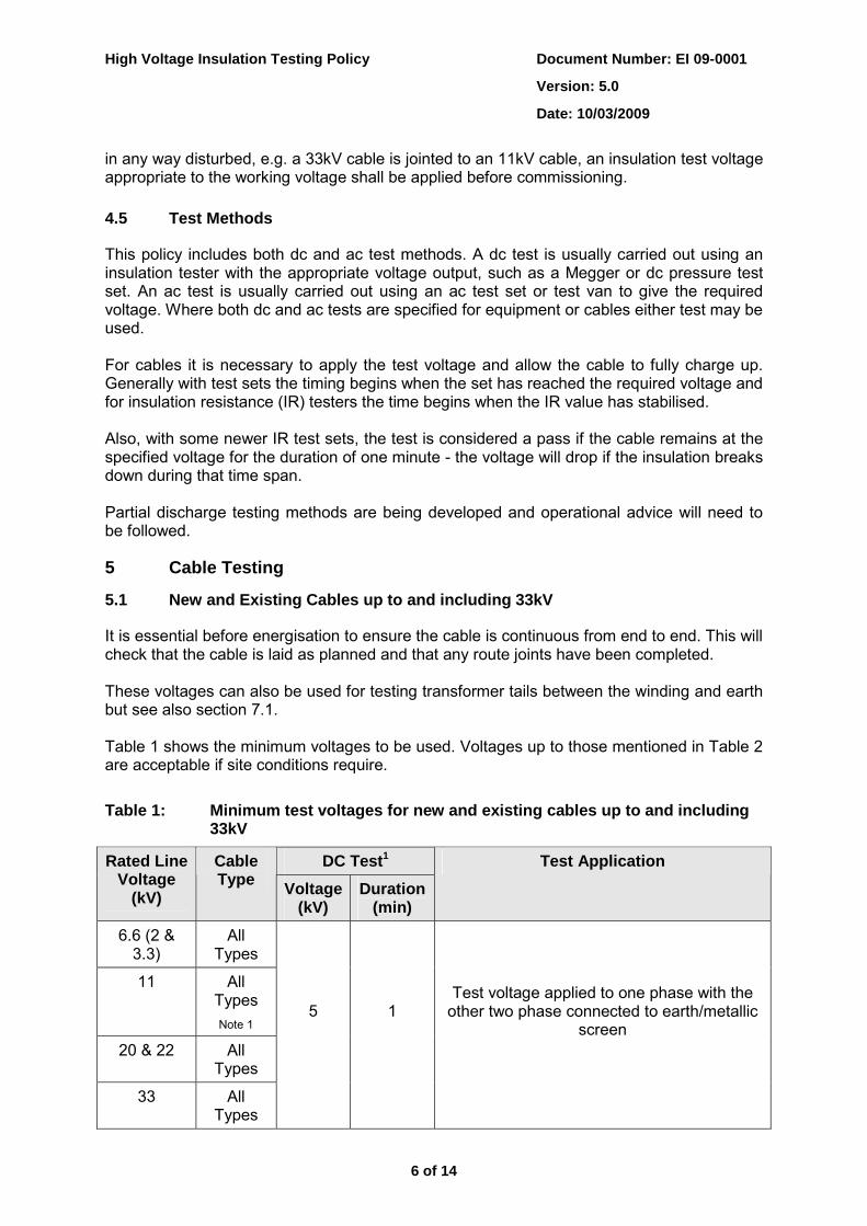
It is essential before energisation to ensure the cable is continuous from end to end. This will check that the cable is laid as planned and that any route joints have been completed. These voltages can also be used for testing transformer tails between the winding and earth but see also section 7.1. Table 1 shows the minimum voltages to be used. Voltages up to those mentioned in Table 2 are acceptable if site conditions require.
Table 1: Minimum test voltages for new and existing cables up to and including 33kV
DC Test1 Rated Line Voltage
(kV)
Cable Type Voltage
(kV) Duration
(min)
Test Application
6.6 (2 & 3.3)
All Types
11 All Types Note 1
20 & 22 All Types
33 All Types
5
1
Test voltage applied to one phase with the other two phase connected to earth/metallic
screen
Document Number: EI 09-0001
Version: 5.0
High Voltage Insulation Testing Policy
Date: 10/03/2009
7 of 14
Notes:
1. Partial discharge mapping carried out in London, mainly at 11kV, is used as a commissioning test. These tests do require the test voltage to be of the order of 1.5Uo ac at 0.1Hz for a period of up to 15 minutes.
5.2 Acceptable IR Values
It is not possible to specify a lowest acceptable insulation resistance value for dc testing (as it depends on a number of factors including cable type/length, weather conditions, etc.) all three cores should be similar and a different value on one core would indicate a problem. The determining factor here will be whether any of the phases has an unacceptably low reading (1MΩ) or a drastically different reading. Engineering judgement needs to be applied to the value obtained. If traditional fault location fails to indicate a fault then connecting the circuit to the network for a 24 hour soak test is acceptable. If customers will be affected by the fault occurring during this test the number of customers must be as low as reasonably practical. 5.3 Cable Fault Location up to 33kV
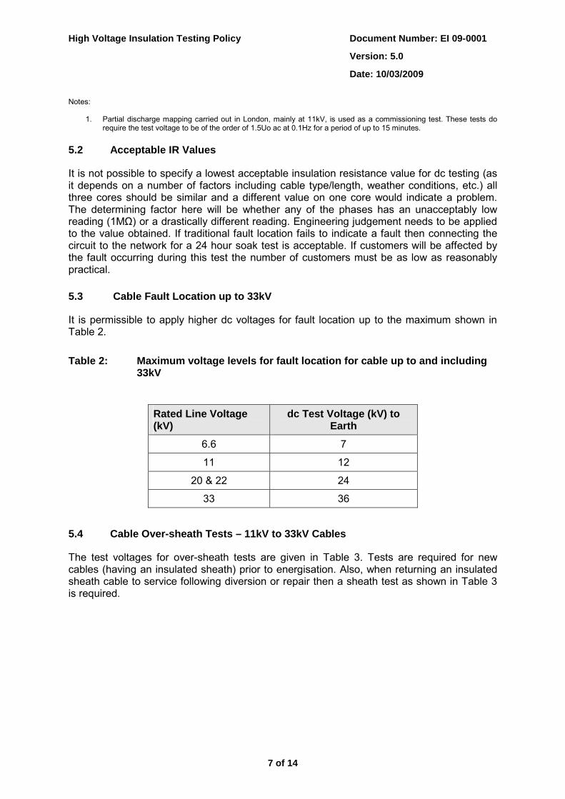
It is permissible to apply higher dc voltages for fault location up to the maximum shown in Table 2.
Table 2: Maximum voltage levels for fault location for cable up to and including 33kV
5.4 Cable Over-sheath Tests – 11kV to 33kV Cables
The test voltages for over-sheath tests are given in Table 3. Tests are required for new cables (having an insulated sheath) prior to energisation. Also, when returning an insulated sheath cable to service following diversion or repair then a sheath test as shown in Table 3 is required.
Rated Line Voltage (kV)
dc Test Voltage (kV) to Earth
6.6 7
11 12
20 & 22 24
33 36

Document Number: EI 09-0001
Version: 5.0
High Voltage Insulation Testing Policy
Date: 10/03/2009
8 of 14
Table 3: Cable over-sheath test voltages for cables up to 33kV
System Nominal
Voltage (kV)
Minimum dc Test Voltage
(kV) New cables
Minimum dc Test Voltage
(kV) On return to
service
Test Duration
(min)
Maximum Leakage Current
(mA)
Test Application
11 Not Applicable
20 & 22 5
33
5
5
1 10
Between metallic
sheath and earth
Note - specially bonded cable circuits complying with the requirements of ENA ER C55/4 may require further tests in addition to the over-sheath tests above.
5.5 New and Existing Cables – 66kV and 132kV Oil and Gas Pressure Assisted Cables
It is essential before energisation to ensure the cable is continuous from end to end. This will check that the cable is laid as planned and that any route joints have been completed. The cable shall withstand a dc test voltage of negative polarity applied between the conductor(s) and sheath with the sheath earthed. Table 4 shows the minimum voltages to be used. No breakdown of the insulation shall occur.
Table 4: Minimum test voltages for new and existing fluid and gas filled 66kV and 132kV cables
Rated Line
Voltage (kV)
dc Test Voltage for New Cable Systems
(kV)
Minimum dc Test Voltage for Systems
with old Cable (kV)
Duration (min)
Test Application
66 170 71
132 305 130 15 Test voltage applied to one phase
with the other two phases connected to earth/metallic screen
5.6 New and Existing Cables - 66kV and 132kV cables containing XLPE insulated
Cable
It is essential before energisation to ensure the cable is continuous from end to end. This will check that the cable is laid as planned and that any route joints have been completed. The cable shall withstand an ac test voltage applied between the conductor(s) and sheath with the sheath earthed. Where possible a Partial Discharge (PD) test shall be carried out during the ac test. The test will normally be provided by a series resonant test set operating close to power frequency.
Document Number: EI 09-0001
Version: 5.0
High Voltage Insulation Testing Policy
Date: 10/03/2009
9 of 14
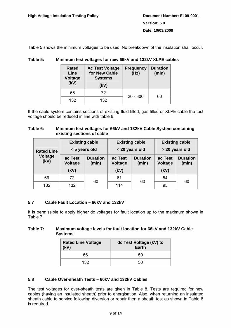
Table 5 shows the minimum voltages to be used. No breakdown of the insulation shall occur.
Table 5: Minimum test voltages for new 66kV and 132kV XLPE cables
Rated Line
Voltage (kV)
Ac Test Voltage for New Cable
Systems (kV)
Frequency (Hz)
Duration (min)
66 72
132 132 20 - 300 60
If the cable system contains sections of existing fluid filled, gas filled or XLPE cable the test voltage should be reduced in line with table 6.
Table 6: Minimum test voltages for 66kV and 132kV Cable System containing existing sections of cable
Existing cable < 5 years old
Existing cable < 20 years old
Existing cable > 20 years old Rated Line
Voltage (kV) ac Test
Voltage (kV)
Duration (min)
ac Test Voltage
(kV)
Duration (min)
ac Test Voltage
(kV)
Duration (min)
66 72 61 54
132 132 60
114 60
95 60
5.7 Cable Fault Location – 66kV and 132kV
It is permissible to apply higher dc voltages for fault location up to the maximum shown in Table 7.
Table 7: Maximum voltage levels for fault location for 66kV and 132kV Cable Systems
Rated Line Voltage (kV)
dc Test Voltage (kV) to Earth
66 50
132 50
5.8 Cable Over-sheath Tests – 66kV and 132kV Cables
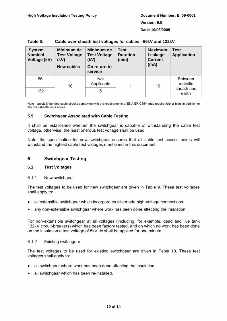
The test voltages for over-sheath tests are given in Table 8. Tests are required for new cables (having an insulated sheath) prior to energisation. Also, when returning an insulated sheath cable to service following diversion or repair then a sheath test as shown in Table 8 is required.
Document Number: EI 09-0001
Version: 5.0
High Voltage Insulation Testing Policy
Date: 10/03/2009
10 of 14
Table 8: Cable over-sheath test voltages for cables - 66kV and 132kV
System Nominal Voltage (kV)
Minimum dc Test Voltage (kV) New cables
Minimum dc Test Voltage (kV) On return to service
Test Duration (min)
Maximum Leakage Current (mA)
Test Application
66 Not Applicable
132 10
5 1 10
Between metallic
sheath and earth
Note - specially bonded cable circuits complying with the requirements of ENA ER C55/4 may require further tests in addition to the over-sheath tests above.
5.9 Switchgear Associated with Cable Testing
It shall be established whether the switchgear is capable of withstanding the cable test voltage, otherwise, the least onerous test voltage shall be used.
Note: the specification for new switchgear ensures that all cable test access points will withstand the highest cable test voltages mentioned in this document.
6 Switchgear Testing
6.1 Test Voltages
6.1.1 New switchgear
The test voltages to be used for new switchgear are given in Table 9. These test voltages shall apply to: • all extensible switchgear which incorporates site made high-voltage connections.
• any non-extensible switchgear where work has been done affecting the insulation.
For non-extensible switchgear at all voltages (including, for example, dead and live tank 132kV circuit-breakers) which has been factory tested, and on which no work has been done on the insulation a test voltage of 5kV dc shall be applied for one minute. 6.1.2 Existing switchgear
The test voltages to be used for existing switchgear are given in Table 10. These test voltages shall apply to: • all switchgear where work has been done affecting the insulation.
• all switchgear which has been re-installed.
Document Number: EI 09-0001
Version: 5.0
High Voltage Insulation Testing Policy
Date: 10/03/2009
11 of 14
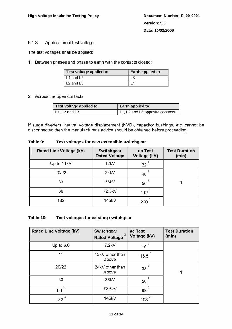
6.1.3 Application of test voltage
The test voltages shall be applied: 1. Between phases and phase to earth with the contacts closed:
Test voltage applied to Earth applied to L1 and L2 L3 L2 and L3 L1
2. Across the open contacts:
Test voltage applied to Earth applied to L1, L2 and L3 L1, L2 and L3 opposite contacts
If surge diverters, neutral voltage displacement (NVD), capacitor bushings, etc. cannot be disconnected then the manufacturer’s advice should be obtained before proceeding.
Table 9: Test voltages for new extensible switchgear
Rated Line Voltage (kV) Switchgear Rated Voltage
ac Test Voltage (kV)
Test Duration (min)
Up to 11kV 12kV 22 1
20/22 24kV 40 1
33 36kV 56 1
66 72.5kV 112 1
132 145kV 220 1
1
Table 10: Test voltages for existing switchgear
Rated Line Voltage (kV) Switchgear Rated Voltage
3ac Test Voltage (kV)
Test Duration (min)
Up to 6.6 7.2kV 10 2
11 12kV other than above
16.5 2
20/22 24kV other than above
33 2
33 36kV 50 2
66 3 72.5kV 99
2
132 3 145kV 198
2
1

Document Number: EI 09-0001
Version: 5.0
High Voltage Insulation Testing Policy
Date: 10/03/2009
12 of 14
Notes: 1. The ac test voltage for new extensible switchgear is 80% of factory test and should also include a 5kV IR result both before and after the ac test. 2. The switchgear will withstand the full test voltage applied to new equipment but to reduce the stress for this and subsequent tests the test voltage for existing switchgear has been reduced to 1.5 times the line voltage. 3. See alternative soak test for 66kV and 132kV GIS switchgear.
6.2 Alternative Soak Test for 66kV and 132kV GIS Switchgear
An alternative regime for retesting, following an earlier full test, 66kV and 132kV GIS switchgear is to connect the switchgear to the network for a 24 hour period to soak test it rather than apply a voltage test.
This test has been approved because:
• The difficulty, expense and risk of providing full test voltage immediately prior to energisation.
• GIS equipment, connecting and disconnecting the test set involves work on the equipment; consequently the reconnection and re-gassing after removing the test set is not then tested.
This option is available to the SAP who will supervise the re-commissioning if: • The switchgear is GIS, requiring opening of gas compartments for connecting and
disconnecting the test connections.
• No external insulation has been disturbed in the parts being tested.
• The protection is arranged such that in the event of a fault on the equipment being tested no loss of supplies to customers shall occur.
• The system fault level is reduced to the lowest possible level and access to the plant under test is restricted.
6.3 Air Insulated Bus Bars and Disconnectors
Testing of air insulated bus bars, air break isolators or post insulators, etc. is not required by this policy providing a visual inspection is made prior to energisation.
7 Transformer Testing The assembly of transformers, transport arrangements, quality controls during installation and sealing is such that high voltage insulation testing is generally unnecessary. Unless otherwise agreed with the manufacturer the only testing required for transformers (including pole-mounted) is insulation resistance testing using the test voltages given in Table 11. The insulation resistance shall be comparable with the original test documentation (if available). If, in order to test other equipment, it is necessary to apply a higher test voltage to the windings, then the voltages given in Table 12 should not be exceeded.

Document Number: EI 09-0001
Version: 5.0
High Voltage Insulation Testing Policy
Date: 10/03/2009
13 of 14
Table 11: Test voltages for transformers
Test System Nominal Voltage (kV)
dc Test Voltage (kV)
Test Duration (min)
Test Application
Up to 6.6
11
22
1
33 1 – 2.5 1
66
Winding Insulation
132 2.5
1
Apply to each winding in turn with the other winding(s)
earthed
Core Insulation All 1 1
Core insulation should be clear of earth with core earth link
removed and connected to earth after core earth link replaced
Notes: The test voltage specified in the manufacturers test documentation should be used.
Table 12: Maximum test voltages for transformers (for example where other
equipment is connected)
System Nominal Voltage (kV)
DC Test Voltage (kV) Test Duration (min)
6.6 6.6
11 11
22 22
33 33
66 66
66 (graded insulation) 30
132 (graded insulation) 50
1
If a higher test voltage is to be considered, the manufacturer should be consulted prior to testing.
7.1 Transformer Tails and Test Access
Where test access is available transformer tails must always be tested. Where test access requires the dismantlement of apparatus and the SAP considers the risk to personnel of gaining the test access is higher than the risk of failure then the test may be omitted. This will usually apply at 11kV primary substations where the cable tails are within the EDF Energy site and there is no reason to believe there has been any damage.
Document Number: EI 09-0001
Version: 5.0
High Voltage Insulation Testing Policy
Date: 10/03/2009
14 of 14
8 Overhead Line Testing Insulation testing of overhead lines is not considered reasonably practicable. However, before commissioning, a visual inspection shall be made of new overhead lines and the modified parts of previously energised lines. Also, before re-commissioning overhead lines that have been de-energised for an extended period of time, a risk assessment shall be made to decide if a visual inspection is required. This assessment shall take into account factors, such as the activity of third parties in the vicinity of the circuit and severe weather conditions.
9 Test Results The results of the tests shall be recorded in the substation log book where available. Additionally the EDF Energy Commissioning Policy (EI 05-1001) provides guidance.