eddyncdt 3060 eddyncdt 3061 - micro-epsilon.com · e-mail [email protected] ... analog output...
TRANSCRIPT

Quick Manual
eddyNCDT 3060
eddyNCDT 3061
US

MICRO-EPSILON MESSTECHNIKGmbH & Co. KGKönigbacher Strasse 15
94496 Ortenburg / Germany
Tel. +49 (0) 8542 / 168-0 Fax +49 (0) 8542 / 168-90e-mail [email protected]
Page 3
General
eddyNCDT 306x
General
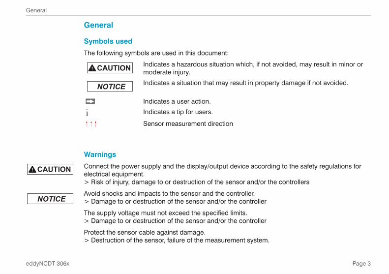
Symbols usedThe following symbols are used in this document:
Indicates a hazardous situation which, if not avoided, may result in minor or moderate injury.
Indicates a situation that may result in property damage if not avoided.
Indicates a user action.
i Indicates a tip for users.
Sensor measurement direction
WarningsConnect the power supply and the display/output device according to the safety regulations for electrical equipment.
> Risk of injury, damage to or destruction of the sensor and/or the controllers
Avoid shocks and impacts to the sensor and the controller. > Damage to or destruction of the sensor and/or the controller
The supply voltage must not exceed the specified limits. > Damage to or destruction of the sensor and/or the controller
Protect the sensor cable against damage. > Destruction of the sensor, failure of the measurement system.
Page 4
General
eddyNCDT 306x
Intended Use - The measuring system is designed for use in an industrial environment. It is used for
� measuring displacement, distance movement and thickness, � measuring the position of parts or machine components.
- The measuring system must only be operated within the limits specified in the technical data. The measuring system must be used in such a way that no persons are endangered or machines and other mate-
rial goods are damaged in the event of malfunction or total failure of the controller.. Take additional precautions for safety and damage prevention in case of safety-related applications.
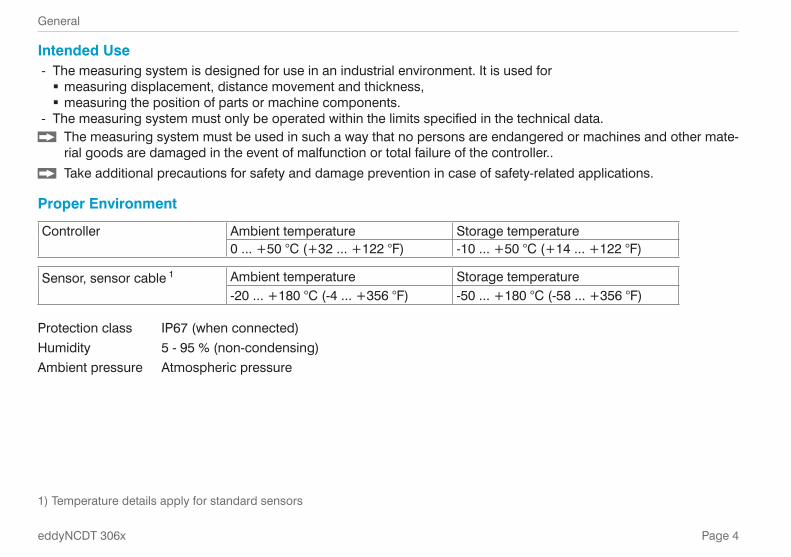
Proper Environment
Controller Ambient temperature Storage temperature0 ... +50 °C (+32 ... +122 °F) -10 ... +50 °C (+14 ... +122 °F)
Sensor, sensor cable 1 Ambient temperature Storage temperature-20 ... +180 °C (-4 ... +356 °F) -50 ... +180 °C (-58 ... +356 °F)
Protection class IP67 (when connected)Humidity 5 - 95 % (non-condensing)Ambient pressure Atmospheric pressure
1) Temperature details apply for standard sensors

Page 5
General
eddyNCDT 306x
Setup, Connection OptionsPower supply and signal output are provided via plug con-nectors on the front of the controller.
SC
D2/
4/R
J45
Sensor
EC
-x/y
Controller
DDxxPS 2020
PCx/8-M12
Ethernet
PC
Pin Assignment Supply, Analog Output
PIN Wire color PCx/8-M12
Signal
2 brown +24 VDC supply, polarity protection7 blue GND supply
1 white U displacement (load min. 10 kOhm)6 pink GND displacement
8 red I displacement (load max. 500 Ohm)
3 green U temp sensor / threshold 1
4 yellow U temp controller / threshold 25 gray GND temperature, thresholdShield
The PCx/8-M12 is a fully assembled power- and output cable; length is 3, 5 or 10 m. The GND analog grounds are connected internally. The outputs are short circuit proof.
2 1
3 74 6
5
8
Pin side 8-pin housing plug
Supply and analog output con-troller, 8-pin male connector
Page 6
General
eddyNCDT 306x
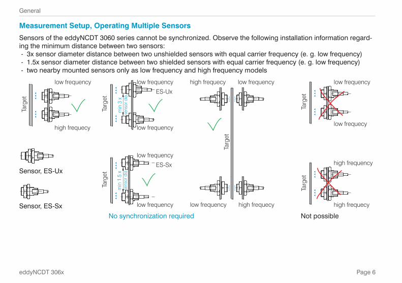
Measurement Setup, Operating Multiple SensorsSensors of the eddyNCDT 3060 series cannot be synchronized. Observe the following installation information regard-ing the minimum distance between two sensors:
- 3x sensor diameter distance between two unshielded sensors with equal carrier frequency (e. g. low frequency) - 1.5x sensor diameter distance between two shielded sensors with equal carrier frequency (e. g. low frequency) - two nearby mounted sensors only as low frequency and high frequency models
low frequency
high frequecy
Targ
et
low frequency
ES-Ux
low frequency
Targ
et
min
3 x
se
nsor
dia
.
Targ
et
low frequencyhigh frequecy
low frequency high frequecy
low frequency
low frequecy
Targ
et
low frequency
ES-Sx
low frequency
Targ
et
min
1.5
x
sens
or d
ia
high frequency
high frequecy
Targ
et
Sensor, ES-Ux
Sensor, ES-SxNo synchronization required Not possible

Page 7
General
eddyNCDT 306x
LED Controller, LED
State
Ethernet
LED Stategreen orange red off
Controller in operation, measurement runs
Software update
Sensor resp. target outside measuring range No sensor connected, threshold or warn level exceeded, error
No power supply
Legend LED
on flashes off
Glossary, Analog Output
SMR Start of measuring range. Minimum distance between sensor front and measuring, sensor specific
MMR MidrangeEMR End of measuring range (Start of measuring
range + measuring range). Maximum distance between sensor front and measuring object.
MR Measuring range
SMR
Sensor
20 mA
12 mA
4 mA
Target
Measuring range (MR)
SMR MMR EMR
Displace-ment
10 V
5 V
0 V
Sig
nal

Page 8
Installation and Assembly
eddyNCDT 306x
Installation and AssemblyNo sharp or heavy objects should be allowed to affect the cable sheath of the sensor cable, the supply cable and the output cable.
i A damaged cable cannot be repaired. Tension on the cable is not permitted!!
SensorUnshielded sensors
- Type designation: ES-Ux - Construction: The sensor cap with encapsulated coil consists of elec-trically non-conducting materials.
i In the radial direction metal parts in the vicinity may behave similar to the measuring object, rendering the measurement result inaccurate. Please note this by selection of material for sensor mounting and their setup.
Shielded sensors - Type designation: ES-Sx - Construction: The sensor en-closed up to its front face with a steel housing with a mount-ing thread. With it the sensor is shielded from interference through radially near located metal parts.
Start of Measuring RangeFor each sensor a minimum distance to the measuring object must be maintained. This avoids a measurement uncertainty due to the sensor pressing on the measuring object and mechanical damage to the sensor/target.
SMR
Sensor Target
Measuring range (MR)
Start of measuring range (SMR), the minimum distance between sensor face and target
Eddy-current displacement sensors can be affected in their measurement properties by a metallic holder. De-pending on the sensor type, the following sensor mount-ing should be preferred:
- unshielded sensors: Standard mounting - shielded sensors: Flush mounting
Page 9
Installation and Assembly
eddyNCDT 306x
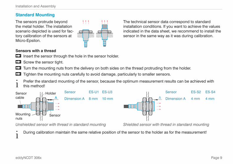
Standard MountingThe sensors protrude beyond the metal holder. The installation scenario depicted is used for fac-tory calibration of the sensors at Micro-Epsilon.
The technical sensor data correspond to standard installation conditions. If you want to achieve the values indicated in the data sheet, we recommend to install the sensor in the same way as it was during calibration.
Sensors with a thread Insert the sensor through the hole in the sensor holder. Screw the sensor tight. Turn the mounting nuts from the delivery on both sides on the thread protruding from the holder. Tighten the mounting nuts carefully to avoid damage, particularly to smaller sensors.
i Prefer the standard mounting of the sensor, because the optimum measurement results can be achieved with this method!
Holder
Mountingnuts
Sensor
Sensor cable A
Sensor ES-U1 ES-U3A
Sensor ES-S2 ES-S4
Dimension A 8 mm 10 mm Dimension A 4 mm 4 mm
Unshielded sensor with thread in standard mounting Shielded sensor with thread in standard mounting
i During calibration maintain the same relative position of the sensor to the holder as for the measurement!
Page 10
Installation and Assembly
eddyNCDT 306x
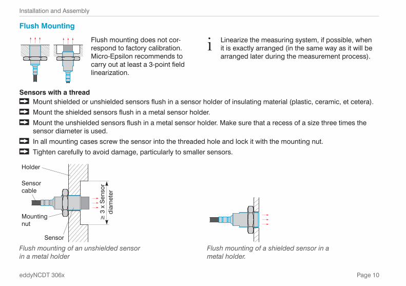
Flush Mounting
Flush mounting does not cor-respond to factory calibration. Micro-Epsilon recommends to carry out at least a 3-point field linearization.
Sensors with a thread Mount shielded or unshielded sensors flush in a sensor holder of insulating material (plastic, ceramic, et cetera). Mount the shielded sensors flush in a metal sensor holder. Mount the unshielded sensors flush in a metal sensor holder. Make sure that a recess of a size three times the
sensor diameter is used. In all mounting cases screw the sensor into the threaded hole and lock it with the mounting nut. Tighten carefully to avoid damage, particularly to smaller sensors.
≥ 3
x S
enso
rdi
amet
er
Holder
Mountingnut
Sensor
Sensorcable
Flush mounting of an unshielded sensor in a metal holder
Flush mounting of a shielded sensor in a metal holder.
i Linearize the measuring system, if possible, when it is exactly arranged (in the same way as it will be arranged later during the measurement process).
Page 11
Installation and Assembly
eddyNCDT 306x
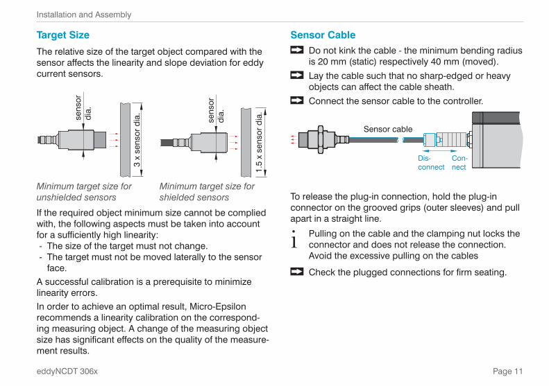
Target SizeThe relative size of the target object compared with the sensor affects the linearity and slope deviation for eddy current sensors.
3 x
sens
or d
ia.
sens
ordi
a.
1.5
x se
nsor
dia
.
sens
or
dia.
Minimum target size for unshielded sensors
Minimum target size for shielded sensors
If the required object minimum size cannot be complied with, the following aspects must be taken into account for a sufficiently high linearity:
- The size of the target must not change. - The target must not be moved laterally to the sensor face.
A successful calibration is a prerequisite to minimize linearity errors.In order to achieve an optimal result, Micro-Epsilon recommends a linearity calibration on the correspond-ing measuring object. A change of the measuring object size has significant effects on the quality of the measure-ment results.
Sensor Cable Do not kink the cable - the minimum bending radius
is 20 mm (static) respectively 40 mm (moved). Lay the cable such that no sharp-edged or heavy
objects can affect the cable sheath. Connect the sensor cable to the controller.
Sensor cable
Dis-connect
Con-nect
To release the plug-in connection, hold the plug-in connector on the grooved grips (outer sleeves) and pull apart in a straight line.
i Pulling on the cable and the clamping nut locks the connector and does not release the connection. Avoid the excessive pulling on the cables
Check the plugged connections for firm seating.
Page 12
Installation and Assembly
eddyNCDT 306x
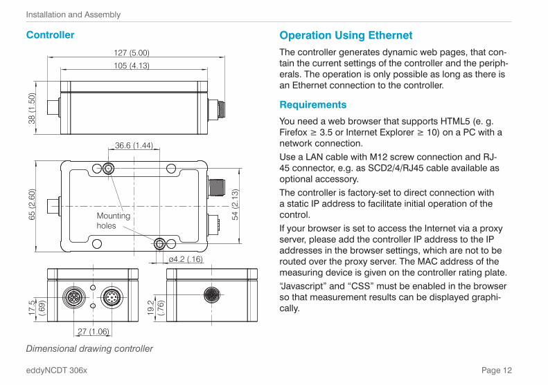
Controller
105 (4.13)
38 (1
.50)
127 (5.00)
19.2
(.76)
27 (1.06)
17.5
(.69)
65 (2
.60)
36.6 (1.44)
Mounting holes
54 (2
.13)
ø4.2 (.16)
Dimensional drawing controller
Operation Using EthernetThe controller generates dynamic web pages, that con-tain the current settings of the controller and the periph-erals. The operation is only possible as long as there is an Ethernet connection to the controller.
RequirementsYou need a web browser that supports HTML5 (e. g. Firefox ≥ 3.5 or Internet Explorer ≥ 10) on a PC with a network connection. Use a LAN cable with M12 screw connection and RJ-45 connector, e.g. as SCD2/4/RJ45 cable available as optional accessory. The controller is factory-set to direct connection with a static IP address to facilitate initial operation of the control. If your browser is set to access the Internet via a proxy server, please add the controller IP address to the IP addresses in the browser settings, which are not to be routed over the proxy server. The MAC address of the measuring device is given on the controller rating plate.“Javascript” and “CSS” must be enabled in the browser so that measurement results can be displayed graphi-cally.
Page 13
Operation Using Ethernet
eddyNCDT 306x
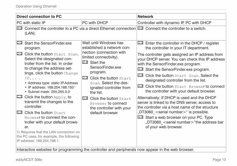
Direct connection to PC NetworkPC with static IP PC with DHCP Controller with dynamic IP, PC with DHCP
Connect the controller to a PC via a direct Ethernet connection (LAN).
Connect the controller to a switch.
Start the SensorFinder.exe program.
Click the button Start Scan. Select the designated con-troller from the list. In order to change the address set-tings, click the button Change IP... .
• Address type: static IP-Address • IP address: 169.254.168.150 1
• Subnet mask: 255.255.0.0 Click the button Apply, to
transmit the changes to the controller.
Click the button Start Browser to connect the con-troller with your default brows-er.
1) Requires that the LAN connection on the PC uses, for example, the following IP address: 169.254.168.1.
Wait until Windows has established a network con-nection (connection with limited connectivity).
Start the SensorFinder.exe program.
Click the button Start Scan. Select the des-ignated controller from the list.
Click the button Start Browser to connect the controller with your default browser.
Enter the controller in the DHCP / register the controller in your IT department.
The controller gets assigned an IP address from your DHCP server. You can check this IP address with the SensorFinder.exe program.
Start the SensorFinder.exe program. Click the button Start Scan. Select the
designated controller from the list. Click the button Start Browser to connect
the controller with your default browser.
Alternatively: If DHCP is used and the DHCP server is linked to the DNS server, access to the controller via a host name of the structure „DT3060_<serial number>“ is possible.
Start a web browser on your PC. Type „DT3060_<serial number>“the address bar of your web browser.
Interactive websites for programming the controller and peripherals now appear in the web browser.

Page 14
Operation Using Ethernet
eddyNCDT 306x
Access via Web Interface
Interactive website after selection of the web interface
Additional help functions (e.g. Settings) are available in the top navigation bar. All settings on the web page are implemented in the controller immediately.Parallel operation with web browser and Telnet com-mands is possible; the last setting applies.The appearance of the web pages can change depend-ing on the functions and the peripherals. Each page contains parameter descriptions and thus tips for config-uring the controller.
Operating Menu, Setting Controller ParametersYou can program eddyNCDT 306x using two different methods simultaneously:
- using the web browser via the sensor web interface - using the ASCII command set and the terminal pro-gram via Ethernet (Telnet).
Login, Change Access Authorization Menu Settings > Login.
Assigning passwords prevents unauthorized changes to controller settings. Password protection is not enabled as a factory setting. After the controller has been config-ured, you should enable password protection.
i A firmware update will not change a custom pass-word.
User can do the following:User Professional
Password required no yesView settings yes yesChange settings, linearization, analog output, password
no yes
Start measuring yes yesScaling diagrams yes yes
Permissions within the user hierarchy

Page 15
Operation Using Ethernet
eddyNCDT 306x
Change in the professional user level
Enter the password into the Password box, and click Login to confirm.Change to the User level by clicking the Logout button.The user management enables to define a user-specific password in Professional mode.
Password Value All passwords are case-sen-sitive. Numbers are allowed, but special characters are not permitted.
When a password is assigned for the first time, the field Old password remains empty.
Scaling Measuring Range Menu Settings > Characteristics > Scale measuring range.
There are two ways to scale the measuring range of the eddyNCDT 306x:
- by using the mouse function directly in the graphic - using the fields Current measuring range be-gin and Current measuring range end.
Scaling the measuring range using the pointer
Scaling of the measuring range has an effect on the analog and digital outputs without increasing the reso-lution.
Page 16
Operation Using Ethernet
eddyNCDT 306x
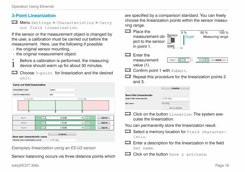
3-Point Linearization Menu Settings > Characteristics > Carry out field linearization.
If the sensor or the measurement object is changed by the user, a calibration must be carried out before the measurement. Here, use the following if possible:
- the original sensor mounting, - the original measurement object.
i Before a calibration is performed, the measuring device should warm up for about 30 minutes.
Choose 3-point for linearization and the desired unit.
Exemplary linearization using an ES-U3 sensor
Sensor balancing occurs via three distance points which
are specified by a comparison standard. You can freely choose the linearization points within the sensor measu-ring range.
Place the measurement ob-ject to the sensor in point 1. SMR
Sensor Target0 % 50 % 100 %
Measuring range
Enter the measurement value (1).
1
Confirm point 1 with Submit. Repeat this procedure for the linearization points 2
and 3.
Click on the button Linearize. The system exe-cutes the linearization.
You can permanently store the linearization result. Select a memory location for Field character-istic.
Enter a description for the linearization in the field Set name.
Click on the button Save & activate.
Page 17
Operation Using Ethernet
eddyNCDT 306x
Here you can export all controller settings in a file or reimport them from a file.Controller settings
Hardware filter, temperature settings, outputs
Ethernet settings
IP address, subnet mask
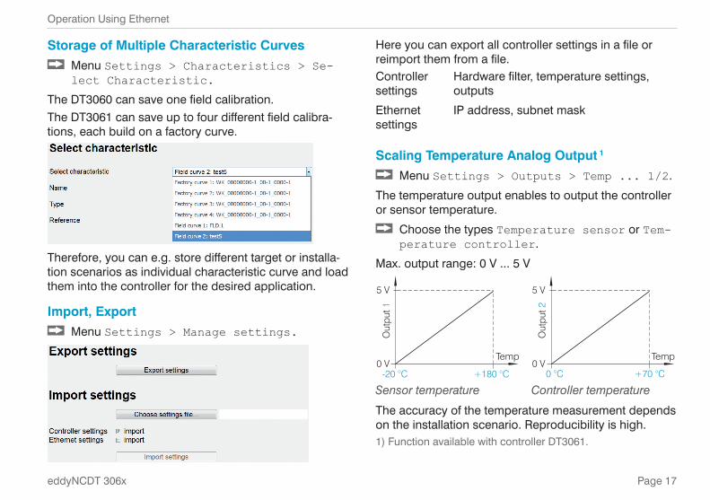
Scaling Temperature Analog Output 1
Menu Settings > Outputs > Temp ... 1/2.
The temperature output enables to output the controller or sensor temperature.
Choose the types Temperature sensor or Tem-perature controller.
Max. output range: 0 V ... 5 V
-20 °C +180 °C
5 V
0 V
Out
put 1
Temp
0 °C +70 °C
5 V
0 V
Out
put 2
Temp
Sensor temperature Controller temperature
The accuracy of the temperature measurement depends on the installation scenario. Reproducibility is high. 1) Function available with controller DT3061.
Storage of Multiple Characteristic Curves Menu Settings > Characteristics > Se-lect Characteristic.
The DT3060 can save one field calibration. The DT3061 can save up to four different field calibra-tions, each build on a factory curve.
Therefore, you can e.g. store different target or installa-tion scenarios as individual characteristic curve and load them into the controller for the desired application.
Import, Export Menu Settings > Manage settings.
Page 18
Operation Using Ethernet
eddyNCDT 306x
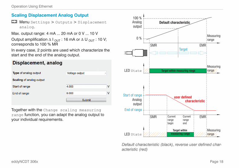
Scaling Displacement Analog Output Menu Settings > Outputs > Displacement analog.
Max. output range: 4 mA ... 20 mA or 0 V ... 10 VOutput amplification D I OUT : 16 mA or D U OUT : 10 V; corresponds to 100 % MR In every case, 2 points are used which characterize the start and the end of the analog output.
Together with the Change scaling measuring range function, you can adapt the analog output to your individual requirements.
SMR EMR
100 %
0 %
Analog output
Measuringrange
LED State
Default characteristic
SMR EMR
Start of range
End of range
Analogoutput
user defined characteristic
Current rangebegin
Currentrange end
Target
Target within measuring range
LED StateTarget within
measuring range
Measuringrange
Measuringrange
Default characteristic (black), reverse user defined char-acteristic (red)
Page 19
Operation Using Ethernet
eddyNCDT 306x
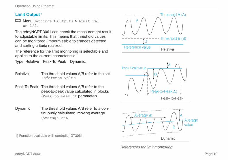
Limit Output 1
Menu Settings > Outputs > Limit val-ue 1/2.
The eddyNCDT 3061 can check the measurement result to adjustable limits. This means that threshold values can be monitored, impermissible tolerances detected and sorting criteria realized.The reference for the limit monitoring is selectable and applies to the current characteristic. Type: Relative | Peak-To-Peak | Dynamic.
Relative The threshold values A/B refer to the set Reference value
Peak-To-Peak The threshold values A/B refer to the peak-to-peak value calculated in blocks (Peak-to-Peak ∆t parameter).
Dynamic The threshold values A/B refer to a con-tinuously calculated, moving average (Average ∆t).
1) Function available with controller DT3061.
Threshold A (A)
Threshold B (B)
Reference value Relative
A
Peak-To-Peak
Dynamic
B
Peak-to-Peak t
Averagevalue
A
B
A
B
Average t
Peak-Peak value
References for limit monitoring

Page 20
Operation Using Ethernet
eddyNCDT 306x
Parameters for limit monitoring
Hold timeON
OFFOut
put 1
/2
t1
Sig
nal
E t < t1
Hysteresis
Thres-hold B
Thres-hold A
Timing limit monitoring, event (E) < hold time, logic: positive
Hold timeON
OFFOut
put 1
/2
t1
Sig
nal
Event
Thres-hold A
Hysteresis
Thres-hold B
Timing limit monitoring, event (E) > hold time, logic: negative
t Duration of limit infringementt 1 Delay timet < t 1 Limit output passivet ≥ t 1 Limit output active

Page 21
Displacement Measurements
eddyNCDT 306x
Positioning the Target Position the target within the sensor measuring
range.
The value for the start of the measuring range (SMR) depends on the sensor. This value can be found in the technical data of the sensor.
SMR
Sensor
20 mA
12 mA
4 mA
Target
Measuring range (MR)
SMR MMR EMR
Displace-ment
10 V
5 V
0 V
Sig
nal
SMR Start of measuring rangeMMR MidrangeEMR End of measuring range
Displacement Measurements Switch to the Measuring > Measuring data display menu.
Click the Start button.
Statistic values are calculated in the web interface. Clicking onto the start/stop button starts/stops the calculation. At the beginning of a measurement, the statistic values are reset. During a measurement, the statistic values are updated with each new data package received by the controller.

Page 22
Service, Repair
eddyNCDT 306x
Service, RepairIn the event of a defect on the controller, sensor or sensor cable, the parts concerned must be sent back for repair or replacement. In the case of faults the cause of which is not clearly identifiable, the whole measuring system must be sent back to
MICRO-EPSILON MESSTECHNIK GmbH & Co. KGKönigbacher Straße 15 94496 Ortenburg / Deutschland
Tel. +49 (0) 8542 / 168-0 Fax +49 (0) 8542 / [email protected]
Liability for Material Defects All components of the device have been checked and tested for functionality at the factory. However, if defects occur despite our careful quality control, MICRO-EPSI-LON or your dealer must be notified immediately.
The liability for material defects is 12 months from deliv-ery. Within this period, defective parts, except for wear-ing parts, will be repaired or replaced free of charge, if the device is returned to MICRO-EPSILON with shipping costs prepaid. Any damage that is caused by improper handling, the use of force or by repairs or modifica-tions by third parties is not covered by the liability for material defects. Repairs are carried out exclusively by MICRO-EPSILON.
Further claims can not be made. Claims arising from the purchase contract remain unaffected. In particular, MI-CRO-EPSILON shall not be liable for any consequential, special, indirect or incidential damage. In the interest of further development, MICRO-EPSILON reserves the right to make design changes without notification. For translations into other languages, the German ver-sion shall prevail.
Page 23
Liability for Material Defects
eddyNCDT 306x
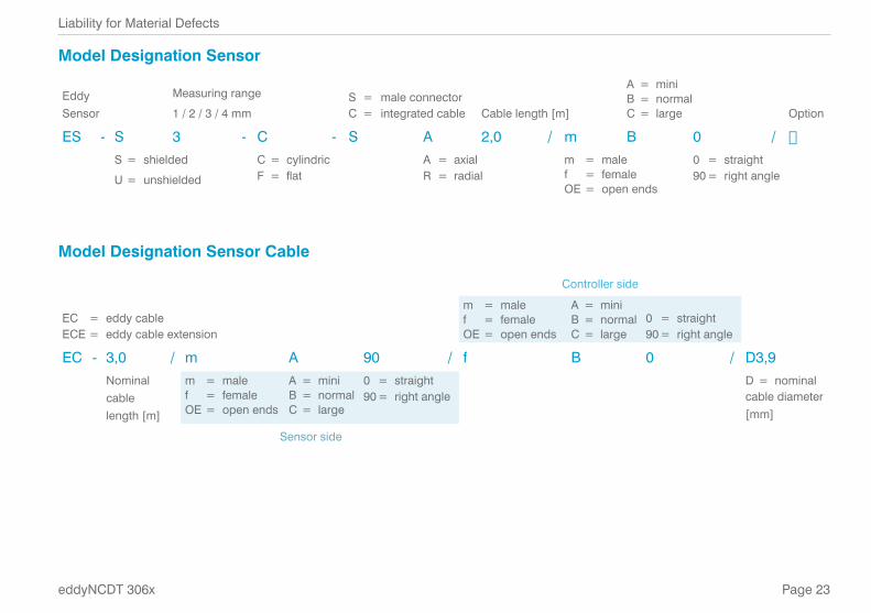
Model Designation Sensor
Eddy Sensor
Measuring range
1 / 2 / 3 / 4 mmS = male connector C = integrated cable Cable length [m]
A = mini B = normal C = large Option
ES - S 3 - C - S A 2,0 / m B 0 / �S = shielded
U = unshielded
C = cylindric F = flat
A = axial R = radial
m = male f = female OE = open ends
0 = straight 90 = right angle
Model Designation Sensor Cable
Controller side
EC = eddy cable ECE = eddy cable extension
m = male f = female OE = open ends
A = mini B = normal C = large
0 = straight 90 = right angle
EC - 3,0 / m A 90 / f B 0 / D3,9Nominal cable length [m]
m = male f = female OE = open ends
A = mini B = normal C = large
0 = straight 90 = right angle
D = nominal cable diameter [mm]
Sensor side
MICRO-EPSILON MESSTECHNIK GmbH & Co. KG
Königbacher Str. 15 · 94496 Ortenburg / Germany
Tel. +49 (0) 8542 / 168-0 · Fax +49 (0) 8542 / 168-90
[email protected] · www.micro-epsilon.de
X9691385-A021098MSC
*X9691385-A01*
MICRO-EPSILON MESSTECHNIK