ed-x45n - estadoc.hitachi.eu projector ed-x45n user's manual (detailed) operating guide thank...
TRANSCRIPT

1
Projector
ED-X45N
User's Manual (detailed) Operating Guide
Thank you for purchasing this projector.
Safety GuideWARNING
NOTE
Trademark acknowledgment
WARNING
CAUTION
®
®
NOTICE

1
About The Symbols Various symbols are used in this manual, the user’s manual and on the productitself to ensure correct usage, to prevent danger to the user and others, and toprevent property damage. The meanings of these symbols are described below.It is important that you read these descriptions thoroughly and fully understandthe contents.
Projector
User's Manual - Safety Guide
Typical Symbols This symbol indicates an additional warning (including cautions). Anillustration is provided to clarify the contents.
This symbol indicates a prohibited action. The contents will be clearlyindicated in an illustration or nearby (the symbol to the left indicates thatdisassembly is prohibited).
This symbol indicates a compulsory action. The contents will be clearlyindicated in an illustration or nearby (the symbol to the left indicates thatthe power plug should be disconnected from the power outlet).
Thank you for purchasing this projector.
NOTE • The information in this manual is subject to change without notice.• The manufacturer assumes no responsibility for any errors that may appear inthis manual.• The reproduction, transmission or use of this document or contents is notpermitted without express written authority.
WARNING • Before using, read these user's manuals of this projector to ensure correct usage through understanding. After reading, store them in a safe place for
future reference. Incorrect handling of this product could possibly result in personal injury or physical damage. The manufacturer assumes no responsibility for any damage caused by mishandling that is beyond normal usage defined in these manuals of this projector.
WARNINGThis symbol indicates information that, if ignored, couldpossibly result in personal injury or even death due toincorrect handling.
CAUTIONThis symbol indicates information that, if ignored, couldresult possibly in personal injury or physical damagedue to incorrect handling.
Read this Safety Guide first.
2
Safety PrecautionsWARNING
Never use the projector if a problem should occur.Abnormal operations such as smoke, strange odor, no image, no sound,excessive sound, damaged casing or elements or cables, penetration ofliquids or foreign matter, etc. can cause a fire or electrical shock.In such case, immediately turn off the power switch and then disconnect thepower plug from the power outlet. After making sure that the smoke or odorhas stopped, contact your dealer. Never attempt to make repairs yourselfbecause this could be dangerous.• The power outlet should be close to the projector and easily accessible.Use special caution for children and pets.Incorrect handling could result in fire, electrical shock, injury, burn or visionproblem.Use special caution in households where children and pets are present.Do not insert liquids or foreign object.Penetration of liquids or foreign objects could result in fire or electrical shock.Use special caution in households where children are present.If liquids or foreign object should enter the projector, immediately turn off thepower switch, disconnect the power plug from the power outlet and contactyour dealer.• Do not place the projector near water (ex. a bathroom, a beach, etc.).• Do not expose the projector to rain or moisture. Do not place the projectoroutdoors.• Do not place flower vases, pots, cups, cosmetics, liquids such as water, etcon or around the projector.• Do not place metals, combustibles, etc on or around the projector.• To avoid penetration of foreign objects, do not put the projector into a case
or bag together with any thing except the accessories of the projector,signal cables and connectors.
Never disassemble and modify.The projector contains high voltage components. Modification and/or disassembly ofthe projector or accessories could result in fire or electrical shock.• Never open the cabinet.• Ask your dealer to repair and clean insider.Do not give the projector any shock or impact.If the projector should be shocked and/or broken, it could result in an injury,and continued use could result in fire or electrical shock.If the projector is shocked, immediately turn off the power switch, disconnectthe power plug from the power outlet and contact your dealer.Do not place the projector on an unstable surface.If the projector should be dropped and/or broken, it could result in an injury,and continued use could result in fire or electrical shock.• Do not place the projector on an unstable, slant or vibrant surface such asa wobbly or inclined stand.• Use the caster brakes placing the projector on a stand with casters.• Do not place the projector in the side up position, the lens up position orthe lens down position.• In the case of a ceiling installation or the like, contact your dealer beforeinstallation.
Disconnect theplug from thepower outlet.
Do notdisassemble.

3
WARNINGBe cautious of High temperatures of the projector.High temperatures are generated when the lamp is lit. It could result in fire orburn. Use special caution in households where children are present.Do not touch about the lens, air fans and ventilation openings during use orimmediately after use, to prevent a burn. Take care of ventilation.• Keep a space of 30 cm or more between the sides and other objects suchas walls.• Do not place the projector on a metallic table or anything weak in heat.• Do not place anything about the lens, air fans and ventilation openings ofthe projector.• Never block the air fan and ventilation openings.• Do not cover the projector with a tablecloth, etc.• Do not place the projector on a carpet or bedding.Never look through the lens or openings when the lamp is on.The powerful light could adversely affect vision.Use special caution in households where children are present.Use only the correct power cord and the correct power outlet.Incorrect power supply could result in fire or electrical shock.• Use only the correct power outlet depending on the indication on theprojector and the safety standard.• The enclosed power cord must be used depending on the power outlet tobe used.Be cautious of the power cord connection.Incorrect connection of the power cord could result in fire or electrical shock.• Do not touch the power cord with a wet hand.• Check that the connecting portion of the power cord is clean (with no dust),before using. Use a soft and dry cloth to clean the power plug.• Insert the power plug into a power outlet firmly. Avoid using a loose,unsound outlet or contact failure.Be sure to connect with ground wire.Connect the ground terminal of AC inlet of this unit with the ground terminalprovided at the building using the correct power cord; otherwise, fire orelectric shock can result.• Don’t take the core of power cord away.
Safety Precautions (continued)
Surely connectthe ground wire.
4
WARNINGBe careful in handling the light source lamp.The projector uses a high-pressure mercury glass lamp made of glass.The lamp can break with a loud bang, or burn out. When the bulb bursts,it is possible for shards of glass to fly into the lamp housing, and for gascontaining mercury to escape from the projector’s vent holes.Please carefully read the section “Lamp”.Be careful in handling the power cord and external connection cables.If you keep using a damaged the power cord or cables, it can cause a fireor electrical shock. Do not apply too much heat, pressure or tension to thepower cord and cables.If the power cord or cables is damaged (exposed or broken core wires, etc.),contact your dealer.• Do not place the projector or heavy objects on the power cord and cables.Also, do not place a spread, cover, etc, over them because this could resultin the inadvertent placing of heavy objects on the concealed power cord orcables.• Do not pul l the power cord and cables. When connect ing anddisconnecting the power cord or cables, do it with your hand holding the plugor connector.• Do not place the cord near the heater.• Avoid bending the power cord sharply.• Do not attempt to work on the power cord.Be careful in handling the battery of the remote control.Incorrect handling of the battery could result in fire or personal injury. Thebattery may explode if not handled properly.• Keep the battery away from children and pets. If swallowed consult aphysician immediately for emergency treatment.• Do not allow the battery in a fire or water.• Avoid fire or high-temperature environment.• Do not hold the battery with the metallic tweezers.• Keep the battery in a dark, cool and dry play.• Do not short circuit the battery.• Do not recharge, disassemble or solder the battery.• Do not give the battery a physical impact.• Use only the battery specified in the other manual of this projector.• Make sure the plus and minus terminals are correctly aligned when loadingthe battery.• If you observe a leakage of the battery, wipe out the flower and thenreplace the battery. If the flower adheres your body or clothes, rinse well withwater.• Obey the local laws on disposing the battery.
Safety Precautions (continued)

5
Safety Precautions (continued)CAUTION
Be careful in moving the projector.Neglect could result in an injury or damage.• Do not move the projector during use. Before moving, disconnect thepower cord and all external connections, and close the slide lens door orattach the lens cap.• Avoid any impact or shock to the projector.• Do not drag the projector.• For moving the projector, use the enclosed case or bag if provided.Do not put anything on top of the projector.Placing anything on the projector could result in loss of balance or falling,and cause an injury or damage. Use special caution in households wherechildren are present.Do not attach anything other than specified things to the projector.Neglect could result in an injury or damage.• Some projector has a screw thread in a lens part. Do not attach anythingother than specified options (such as conversion lens) to the screw thread.Avoid a smoky, humid or dusty place.Placing the projector in a smoke, a highly humid, dusty place, oily soot orcorrosive gas could result in fire or electrical shock.• Do not place the projector near a smoky, humid or dusty place (ex.a smoking space, a kitchen, a beach, etc.). Do not place the projectoroutdoors.• Do not use a humidifier near the projector.Take care of the air filter to normal ventilate.The air filter should be cleaned periodically. If the air filter becomes cloggedby dust or the like, internal temperature rises and could cause malfunction.The projector may display the message such as “CHECK THE AIR FLOW”or turn off the projector, to prevent the internal heat level rising.• When the indicators or a message prompts you to clean the air filter, cleanthe air filter as soon as possible.• If the soiling will not come off the air filter, or it becomes damaged, replacethe air filter.• Use the air filter of the specified type only. Please order the air filterspecified in the other manual of this projector to your dealer.• When you replace the lamp, replace also the air filter. The air filter may beattached when you buy a replacement lamp for this projector.• Do not turn on the projector without air filter.Avoid a high temperature environment.The heat could have adverse influence on the cabinet of the projector andother parts. Do not place the projector, the remote control and other parts indirect sunlight or near a hot object such as heater, etc.Avoid Magnetism. Manufacture strongly recommends to avoid any magnetic contact that is notshielded or protected on or near the projector itself. (ie.,. Magnetic SecurityDevices, or other projector accessory that contains magnetic material that has notbeen provided by the manufacture etc.) Magnetic objects may cause interruptionof the projector's internal mechanical performance which may interfere with coolingfans speed or stopping, and may cause the projector to completely shut down.
6
Safety Precautions (continued)
NOTEDo not give the remote control any physical impact.A physical impact could cause damage or malfunction of the remote control.• Take care not to drop the remote control.• Do not place the projector or heavy objects on the remote control.Take care of the lens.• Close the slide lens door or attach the lens cap to prevent the lens surface beingscratched when the projector is not used.• Do not touch the lens to prevent fog or dirt of the lens that cause deterioration of displayquality.• Use commercially available lens tissue to clean the lens (used to clean cameras,eyeglasses, etc.). Be careful not to scratch the lens with hard objects.Take care of the cabinet and the remote control. Incorrect care could have adverse influence such as discoloration, peeling paint, etc.• Use a soft cloth to clean the cabinet and control panel of the projector and the remotecontrol. When excessively soiled dilute a neutral detergent in water, wet and wring out thesoft cloth and afterward wipe with a dry soft cloth. Do not use undiluted detergent directly.• Do not use an aerosol sprays, solvents, volatile substances or abrasive cleaner.• Before using chemical wipes, be sure to read and observe the instructions.• Do not allow long-term close contact with rubber or vinyl.About bright spots or dark spots.Although bright spots or dark spots may appear on the screen, this is a unique characteristic ofliquid crystal displays, and such do not constitute or imply a machine defect.Be careful of printing of the LCD panel.If the projector continues projecting a still image, inactive images or 16:9 aspect images incase of 4:3 panel, etc., for long time, the LCD panel might possibly be printed.
CAUTIONRemove the power cord for complete separation. • For safety purposes, disconnect the power cord if the projector is not to beused for prolonged periods of time.• Before cleaning, turn off and unplug the projector. Neglect could result infire or electrical shock.Ask your dealer to cleaning inside of the projector about every year.Accumulations of dust inside the projector cause result in fire or malfunction.Cleaning inside is more effective if performed before every humid periodssuch as rainy season.• Do not clean inside yourself because it is dangerous.
Disconnect theplug from thepower outlet.

7
Safety Precautions (continued)NOTEAbout consumables. Lamp, LCD panels, polarizors and other optical components, and air filter and cooling fanshave a different lifetime in each. These parts may need to be replaced after a long usagetime.• This product isn’t designed for continuous use of long time. In the case of continuous usefor 6 hours or more, or use for 6 hours or more every day (even if it isn’t continuous), orrepetitious use, the lifetime may be shortened, and these parts may need to be replacedeven if one year has not passed since the beginning of using.• Any inclining use beyond the adjustment range explained in these user’s manuals may
shorten the lifetimes of the consumables.Before turning on the power, make the projector cool down adequately.After turning the projector off, pushing the restart switch or interrupting of the power supply,make the projector cool down adequately. Operation in a high temperature state of theprojector causes a damage of the electrode and un-lighting of the lamp.Avoid strong rays.Any strong ray (such as direct rays of the sun or room lighting) onto the remote control sensors could invalidate the remote control.Avoid radio interference.Any interfering radiation could cause disordered image or noises.• Avoid radio generator such as a mobile telephone, transceiver, etc. around the projector.About displaying characteristic.The display condition of the projector (such as color, contrast, etc.) depends oncharacteristic of the screen, because the projector uses a liquid crystal display panel. Thedisplay condition can differ from the display of CRT.• Do not use a polarized screen. It can cause red image.Turn the power on/off in right order.To prevent any trouble, turn on/off the projector in right order mentioned below unlessspecifying.• Power on the projector before the computer or video tape recorder.• Power off the projector after the computer or video tape recorder.Take care not to fatigue your eyes.Rest the eyes periodically.Set the sound volume at a suitable level to avoid bothering other people.• It is better to keep the volume level low and close the windows at night to protect theneighborhood environment.Connecting with notebook computerWhen connecting with notebook computer, set to valid the RGB external image output(setting CRT display or simultaneous display of LCD and CRT).Please read instruction manual of the notebook for more information.
8
• If the lamp should break (it will make a loud bang when it does), unplugthe power cord from the outlet, and make sure to request a replacementlamp from your local dealer. Note that shards of glass could damage theprojector’s internals, or cause injury during handling, so please do not try toclean the projector or replace the lamp yourself.• If the lamp should break (it will make a loud bang when it does), ventilatethe room well, and make sure not to breathe the gas that comes out of theprojector vents, or get it in your eyes or mouth.• Before replacing the lamp, make sure the power switch is off and thepower cable is not plugged in, then wait at least 45 minutes for the lamp tocool sufficiently. Handling the lamp while hot can cause burns, as well asdamaging the lamp.
Lamp
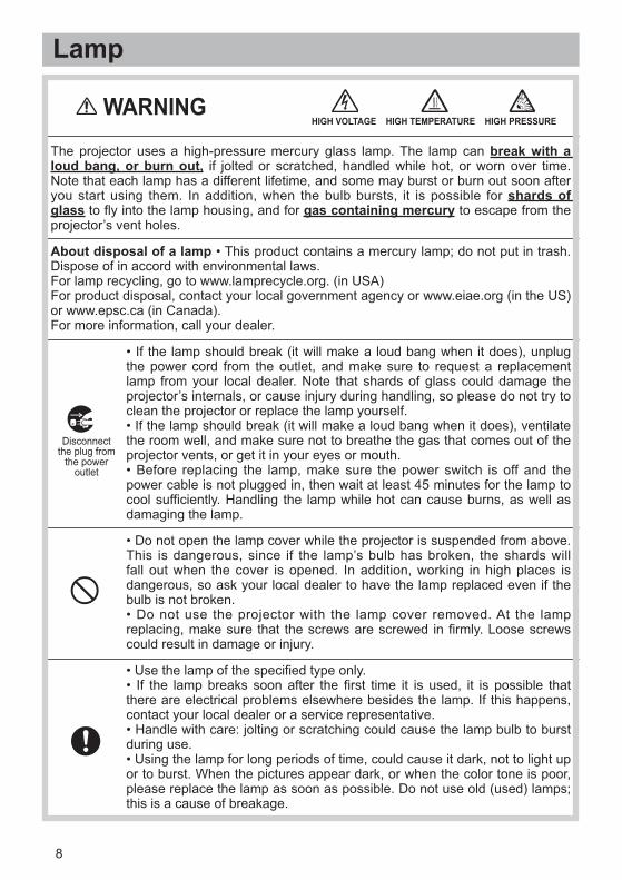
The projector uses a high-pressure mercury glass lamp. The lamp can break with a loud bang, or burn out, if jolted or scratched, handled while hot, or worn over time.Note that each lamp has a different lifetime, and some may burst or burn out soon afteryou start using them. In addition, when the bulb bursts, it is possible for shards of glass to fly into the lamp housing, and for gas containing mercury to escape from theprojector’s vent holes.
About disposal of a lamp • This product contains a mercury lamp; do not put in trash.Dispose of in accord with environmental laws.For lamp recycling, go to www.lamprecycle.org. (in USA)For product disposal, contact your local government agency or www.eiae.org (in the US)or www.epsc.ca (in Canada).For more information, call your dealer.
• Do not open the lamp cover while the projector is suspended from above.This is dangerous, since if the lamp’s bulb has broken, the shards willfall out when the cover is opened. In addition, working in high places isdangerous, so ask your local dealer to have the lamp replaced even if thebulb is not broken.• Do not use the projector with the lamp cover removed. At the lampreplacing, make sure that the screws are screwed in firmly. Loose screwscould result in damage or injury.
• Use the lamp of the specified type only.• If the lamp breaks soon after the first time it is used, it is possible thatthere are electrical problems elsewhere besides the lamp. If this happens,contact your local dealer or a service representative.• Handle with care: jolting or scratching could cause the lamp bulb to burstduring use.• Using the lamp for long periods of time, could cause it dark, not to light upor to burst. When the pictures appear dark, or when the color tone is poor,please replace the lamp as soon as possible. Do not use old (used) lamps;this is a cause of breakage.
WARNINGHIGH VOLTAGE HIGH TEMPERATURE HIGH PRESSURE
Disconnectthe plug from
the poweroutlet

9
Regulatory NoticesFCC Statement WarningThis device complies with part 15 of the FCC Rules. Operation is subject to the followingtwo conditions: (1) This device may not cause harmful interference, and (2) this devicemust accept any interference received, including interference that may cause undesiredoperation.WARNING: This equipment has been tested and found to comply with the limits for aClass B digital device, pursuant to Part 15 of the FCC Rules. These limits are designedto provide reasonable protection against harmful interference in a residential installation.This equipment generates, uses, and can radiate radio frequency energy and, if notinstalled and used in accordance with the instructions, may cause harmful interferenceto radio communications. However, there is no guarantee that interference will not occurin a particular installation. If this equipment does cause harmful interference to radioor television reception, which can be determined by turning the equipment off and on,the user is encouraged to try to correct the interference by one or more of the followingmeasures:- Reorient or relocate the receiving antenna.- Increase the separation between the equipment and receiver.- Connect the equipment into an outlet on a circuit different from that to which the receiveris connected.- Consult the dealer or an experienced radio/TV technician for help.INSTRUCTIONS TO USERS: This equipment complies with the requirements of FCC(Federal Communication Commission) equipment provided that the following conditionsare met. Some cables have to be used with the core set. Use the accessory cable or adesignated-type cable for the connection. For cables that have a core only at one end,connect the core to the projector.CAUTION: Changes or modifications not expressly approved by the party responsible forcompliance could void the user’s authority to operate the equipment.
For the Customers in CANADANOTICE: This Class B digital apparatus complies with Canadian ICES-003.
Warranty And After-ServiceUnless seen any abnormal operations (mentioned with the first paragraph ofWARNING in this manual), when a problem occurs with the equipment, first refer to the“Troubleshooting” section of the “Operating Guide”, and run through the suggested checks.If this does not resolve the problem contact your dealer or service company. They will tellyou what warranty condition is applied.
2
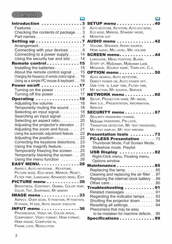
Introduction . . . . . . . . . . . . . . . 3334
Setting up . . . . . . . . . . . . . . . . . 779
1414
Remote control . . . . . . . . . . . . 1515151616
Power on/off . . . . . . . . . . . . . . 171717
Operating . . . . . . . . . . . . . . . . 181818182020212122222324252526
EASY MENU. . . . . . . . . . . . . . . 28ASPECT, AUTO KEYSTONE , KEYSTONE,PICTURE MODE, ECO MODE, MIRROR, RESET,FILTER TIME, LANGUAGE, ADVANCED MENU, EXIT
PICTURE menu . . . . . . . . . . . . 30BRIGHTNESS, CONTRAST, GAMMA, COLOR TEMP,COLOR, TINT, SHARPNESS, MY MEMORY
IMAGE menu . . . . . . . . . . . . . . 33ASPECT, OVER SCAN, V POSITION, H POSITION,H PHASE, H SIZE, AUTO ADJUST EXECUTE
INPUT menu . . . . . . . . . . . . . . 36PROGRESSIVE, VIDEO NR, COLOR SPACE,COMPONENT, VIDEO FORMAT, HDMI FORMAT,HDMI RANGE, COMPUTER IN,FRAME LOCK, RESOLUTION
SETUP menu . . . . . . . . . . . . . . 40AUTO KEYSTONE, KEYSTONE, AUTO ECO MODE,ECO MODE, MIRROR, STANDBY MODE,MONITOR OUT
AUDIO menu . . . . . . . . . . . . . . 42VOLUME, SPEAKER, AUDIO SOURCE,HDMI AUDIO, MIC LEVEL, MIC VOLUME
SCREEN menu. . . . . . . . . . . . . 44LANGUAGE, MENU POSITION, BLANK,START UP, , ,MESSAGE, SOURCE NAME, TEMPLATE, C.C.
OPTION menu . . . . . . . . . . . . . 50AUTO SEARCH, AUTO KEYSTONE,DIRECT POWER ON, AUTO POWER OFF,USB TYPE B, LAMP TIME, FILTER TIME,MY BUTTON, MY SOURCE, SERVICE
NETWORK menu . . . . . . . . . . . 60SETUP, PROJECTOR NAME, MY IMAGE,AMX D.D., PRESENTATION, INFORMATION,SERVICE
SECURITY menu . . . . . . . . . . . 67SECURITY PASSWORD CHANGE,
yScreen PASSWORD, PIN LOCK,TRANSITION DETECTOR, MY TEXT PASSWORD,MY TEXT DISPLAY, MY TEXT WRITING
Presentation tools . . . . . . . . . 73PC-LESS Presentation 73
USB Display . . . . . . . . . . . . . 82
Maintenance . . . . . . . . . . . . . . 8585878990
Troubleshooting . . . . . . . . . . . 9191939494
95. . . . . . . . . . . . . 99
3
Introduction
NOTE
Checking the contents of package
HDMI
USBTYPE A
Contents of package User’s Manual (concise)
Features
4
Introduction
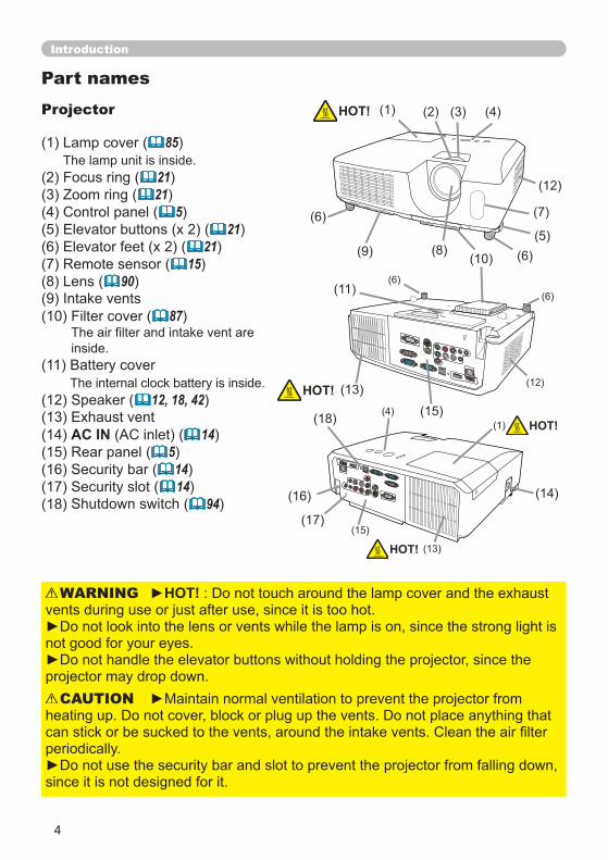
Projector
85
2121
521
2115
90
87
(12 12, 18, 42(13(14 AC IN 14(15 5(16 14(17 14(18 94
HOT!WARNING
CAUTION
HOT!
HOT! (13
HOT!
(12
(15
(16 (14
(13
(17
(15HOT!(18
Part names
5
Introduction
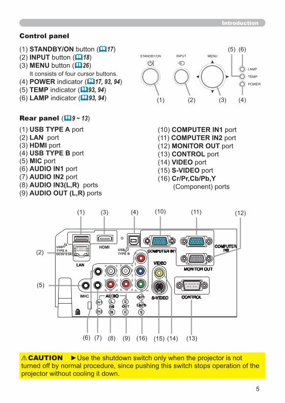
Control panel
STANDBY/ON 17INPUT 18MENU 26
POWER 17, 93, 94TEMP 93, 94LAMP 93, 94
Rear panel ( 9 ~ 13( USB TYPE A
LAN HDMIUSB TYPE B
MICAUDIO IN1AUDIO IN2AUDIO IN3(L,R)AUDIO OUT (L,R)
CAUTION
COMPUTER IN1COMPUTER IN2MONITOR OUTCONTROLVIDEOS-VIDEOCr/Pr,Cb/Pb,Y
LAN
MIC
HDMI
IN1
IN2
USBTYPE ADC5V 0.5A
USBTYPE B
6
Introduction
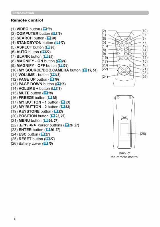
Remote control
VIDEO 19COMPUTER 19SEARCH 20STANDBY/ON 17ASPECT 20AUTO 22BLANK 25MAGNIFY - ON 24MAGNIFY - OFF 24MY SOURCE/DOC.CAMERA 19, 54VOLUME - 18PAGE UP 16PAGE DOWN 16VOLUME + 18MUTE 18FREEZE 25MY BUTTON - 1 53MY BUTTON - 2 53KEYSTONE 23POSITION 22, 27MENU 26, 27
26, 27ENTER 26, 27ESC 27RESET 27
15
VIDEO DOC.CAMERA
KEYSTONE
ASPECT SEARCH BLANK
MUTEMY BUTTON
POSITION
1 2
ESC
ENTER
MENU
RESET
COMPUTERMY SOURCE/
AUTO
MAGNIFY PAGE UP
VOLUME
DOWN
ON
OFF
FREEZE
7
Setting up
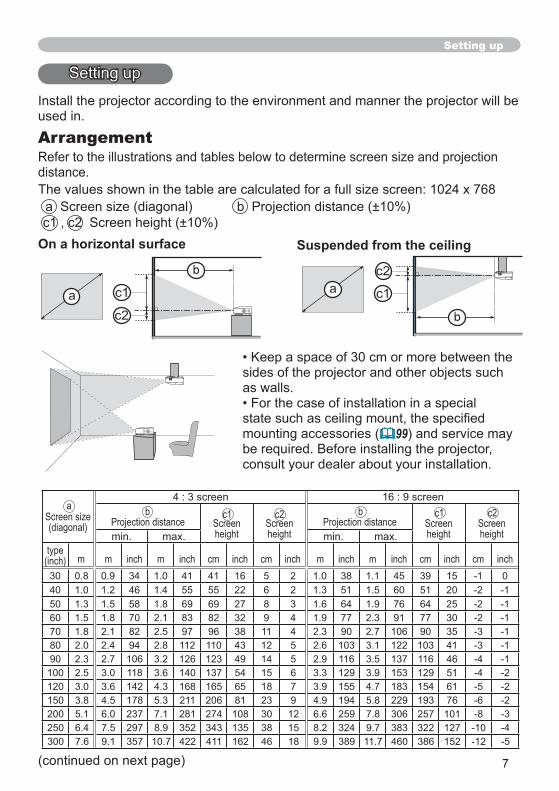
Arrangement
On a horizontal surface Suspended from the ceiling
( 99
Screen size(diagonal) Projection distance Screen
heightScreenheight
Projection distance Screenheight
Screenheight
type(inch) m m inch m inch cm inch cm inch m inch m inch cm inch cm inch30 34 41 41 16 5 2 38 45 39 15 040 46 55 55 22 6 2 51 60 51 2050 58 69 69 27 8 3 64 76 64 2560 70 83 82 32 9 4 77 91 77 3070 82 97 96 38 11 4 90 106 90 3580 94 112 110 43 12 5 103 122 103 4190 106 126 123 49 14 5 116 137 116 46100 118 140 137 54 15 6 129 153 129 51120 142 168 165 65 18 7 155 183 154 61150 178 211 206 81 23 9 194 229 193 76200 237 281 274 108 30 12 259 306 257 101250 297 352 343 135 38 15 324 383 322 127300 357 422 411 162 46 18 389 460 386 152
ba b c1c1 c2 c2
8
Setting up
WARNING
CAUTION
Arrangement (continued)
9
Setting up
WARNING
CAUTION
COMPUTER IN1
About Plug-and-Play capability
Connecting with your devices
10
RL
CO
MPO
NEN
T
Cb/P
bY
Cr/P
r
AU
DIO
OU
T
MIC
HDMIUSBTYPE B
USBTYPE ADC5V 0.5A
LAN
COMPUTER IN1
COMPUTERIN2
VIDEO
S-VIDEO CONTROL
MONITOR OUT
AUDIO
OUTIN3IN1
IN2
L
R
L
R YCb/Pb
Cr/Pr
HD
MI
RL
RL
VIDE
OS-
VIDE
O
AU
DIO
OU
TA
UD
IOO
UT
AUDIOO
UTUSB(A)
DISPLAYRS-232C
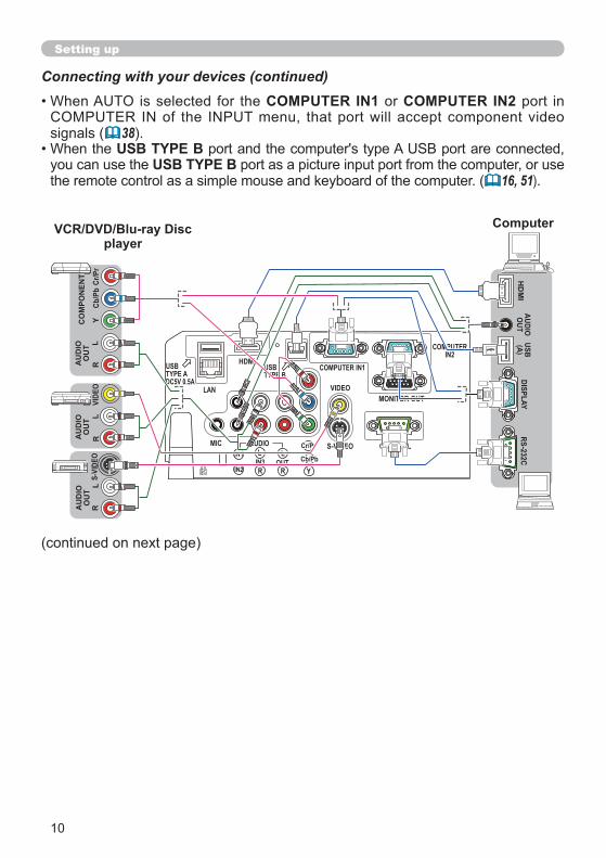
Connecting with your devices (continued)COMPUTER IN1 COMPUTER IN2
( 38USB TYPE B
USB TYPE B( 16, 51)
Setting up
VCR/DVD/Blu-ray Discplayer
Computer
11
Connecting with your devices (continued)
( 38)
NOTE
Setting up
12
Connecting with your devices (continued)
Setting up
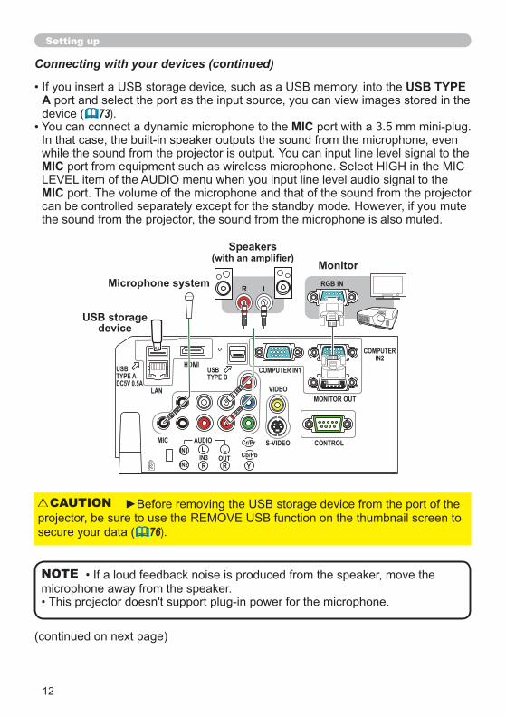
USB TYPE A
( 73)MIC
MIC
MIC
NOTE
USB storage device
( 76)
CAUTION
Microphone system
SpeakersMonitor
MIC
HDMIUSBTYPE B
USBTYPE ADC5V 0.5A
LAN
COMPUTER IN1
COMPUTERIN2
VIDEO
S-VIDEO CONTROL
MONITOR OUT
AUDIO
OUTIN3IN1
IN2
L
R
L
R YCb/Pb
Cr/Pr
R LRGB IN
13
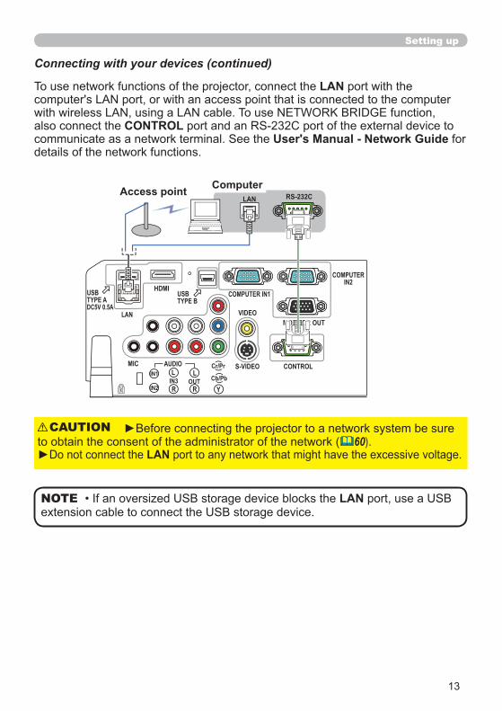
Connecting with your devices (continued)
LAN
CONTROL User's Manual - Network Guide
Setting up
( 60)LAN
CAUTION
LANNOTE
MIC
HDMIUSBTYPE B
USBTYPE ADC5V 0.5A
LAN
COMPUTER IN1
COMPUTERIN2
VIDEO
S-VIDEO CONTROL
MONITOR OUT
AUDIO
OUTIN3IN1
IN2
L
R
L
R YCb/Pb
Cr/Pr
RS-232CLANAccess point Computer
14
Setting up
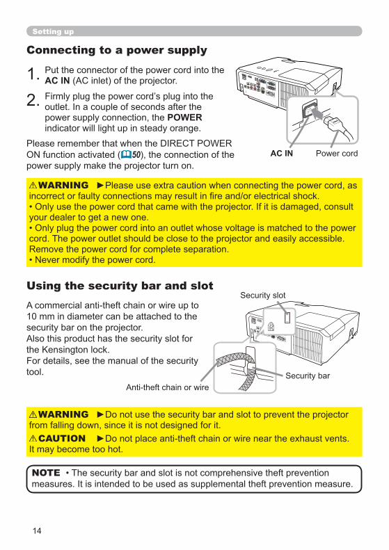
Connecting to a power supply
AC IN
POWER
WARNING
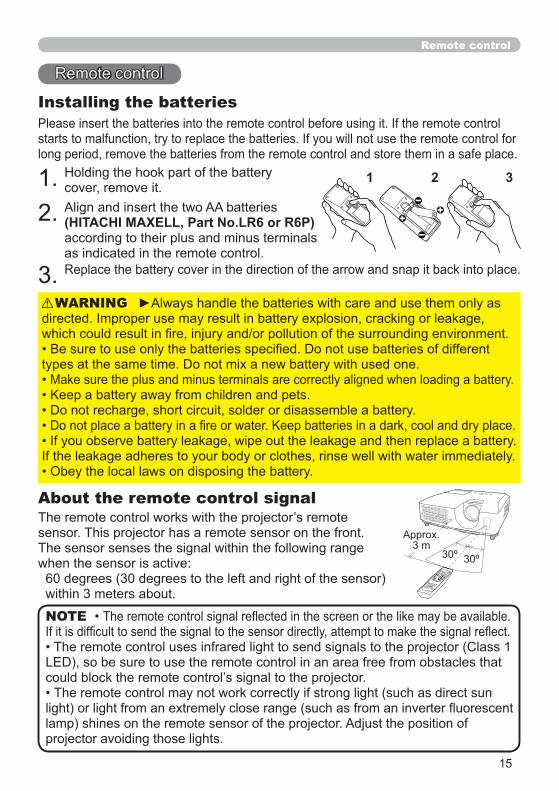
Using the security bar and slot
AC IN
WARNING
CAUTION
NOTE
50
15
30º 30º
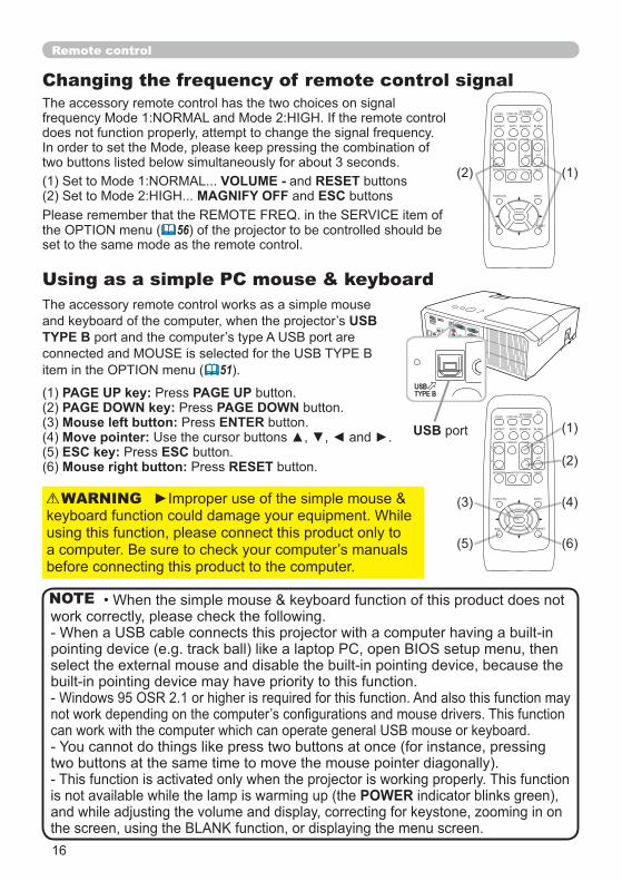
Remote control
About the remote control signal
Installing the batteries
(HITACHI MAXELL, Part No.LR6 or R6P)
WARNING
NOTE
21 3
16
Remote control
Changing the frequency of remote control signal
Using as a simple PC mouse & keyboard
USBTYPE B
51
VIDEO DOC.CAMERA
KEYSTONE
ASPECT SEARCH BLANK
MUTEMY BUTTON
POSITION
1 2
ESC
ENTER
MENU
RESET
COMPUTERMY SOURCE/
AUTO
MAGNIFY PAGE UP
VOLUME
DOWN
ON
OFF
FREEZE
VIDEO DOC.CAMERA
KEYSTONE
ASPECT SEARCH BLANK
MUTEMY BUTTON
POSITION
1 2
ESC
ENTER
MENU
RESET
COMPUTERMY SOURCE/
AUTO
MAGNIFY PAGE UP
VOLUME
DOWN
ON
OFF
FREEZE
PAGE UP key: PAGE UPPAGE DOWN key: PAGE DOWNMouse left button: ENTERMove pointer:ESC key: ESCMouse right button: RESET
WARNING
POWER
NOTE
VOLUME - RESETMAGNIFY OFF ESC
56
USBTYPE B
USB
17
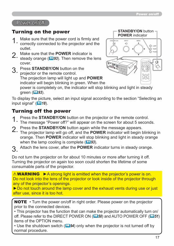
Power on/off
Turning on the power
POWER93
STANDBY/ON
POWER
93
18
WARNING
STANDBY/ONTurning off the power
STANDBY/ONPOWER
POWER93
POWER
STANDBY/ONPOWER
( 50 ( 51
94
NOTE
VIDEO DOC.CAMERA
KEYSTONE
ASPECT SEARCH BLANK
MUTEMY BUTTON
POSITION
1 2
ESC
ENTER
MENU
RESET
COMPUTERMY SOURCE/
AUTO
MAGNIFY PAGE UP
VOLUME
DOWN
ON
OFF
FREEZE
18
Operating
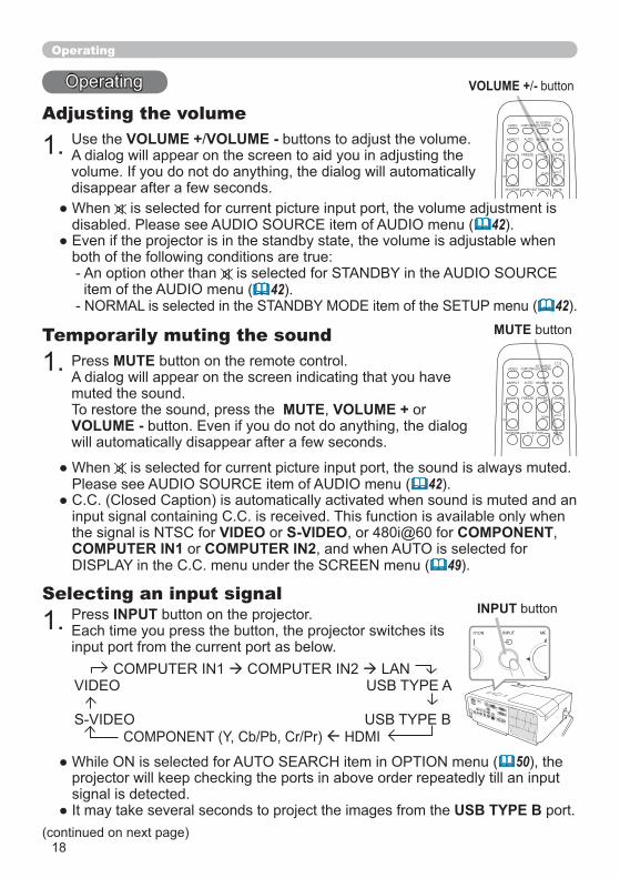
Adjusting the volumeVOLUME + VOLUME -
42
42( 42
MUTE
MUTE VOLUME +VOLUME -
Temporarily muting the sound
42
VIDEO S-VIDEO COMPONENTCOMPUTER IN1 COMPUTER IN2
49
INPUTSelecting an input signal
VOLUME + -
INPUT
MUTE
50
USB TYPE B
VIDEO DOC.CAMERA
KEYSTONE
ASPECT SEARCH BLANK
MUTEMY BUTTON1 2
COMPUTERMY SOURCE/
AUTO
MAGNIFY PAGE UP
VOLUME
DOWN
ON
OFF
FREEZE
VIDEO DOC.CAMERA
KEYSTONE
ASPECT SEARCH BLANK
MUTEMY BUTTON1 2
COMPUTERMY SOURCE/
AUTO
MAGNIFY PAGE UP
VOLUME
DOWN
ON
OFF
FREEZE
19
VIDEO DOC.CAMERA
KEYSTONE
ASPECT SEARCH BLANK
MUTEMY BUTTON
POSITION
1 2
MENU
COMPUTERMY SOURCE/
AUTO
MAGNIFY PAGE UP
VOLUME
DOWN
ON
OFF
FREEZE
Operating
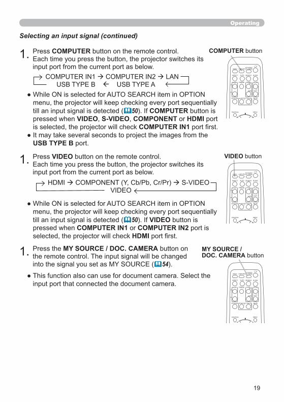
VIDEO
Selecting an input signal (continued)
50 VIDEOCOMPUTER IN1 COMPUTER IN2
HDMI
VIDEO
VIDEO DOC.CAMERA
KEYSTONE
ASPECT SEARCH BLANK
MUTEMY BUTTON
POSITION
1 2
MENU
COMPUTERMY SOURCE/
AUTO
MAGNIFY PAGE UP
VOLUME
DOWN
ON
OFF
FREEZE
MY SOURCE / DOC. CAMERA
COMPUTER
50 COMPUTERVIDEO S-VIDEO COMPONENT HDMI
COMPUTER IN1
USB TYPE B
COMPUTER
VIDEO DOC.CAMERA
KEYSTONE
ASPECT SEARCH BLANK
MUTEMY BUTTON
POSITION
1 2
MENU
COMPUTERMY SOURCE/
AUTO
MAGNIFY PAGE UP
VOLUME
DOWN
ON
OFF
FREEZE
MY SOURCE / DOC. CAMERA
54
20
VIDEO DOC.CAMERA
KEYSTONE
ASPECT SEARCH BLANK
MUTEMY BUTTON
POSITION
1 2
MENU
COMPUTERMY SOURCE/
AUTO
MAGNIFY PAGE UP
VOLUME
DOWN
ON
OFF
FREEZE
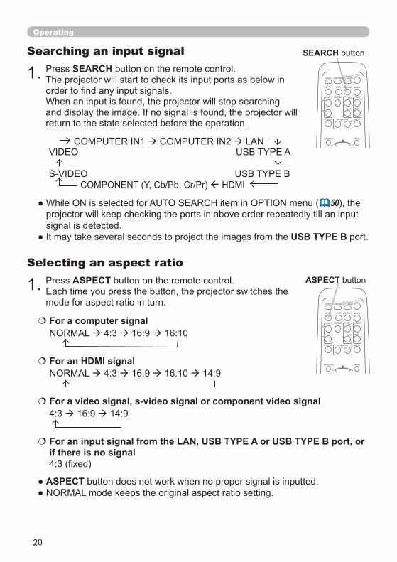
ASPECT
Selecting an aspect ratio
ASPECT
SEARCH
Searching an input signal
50
USB TYPE B
For a computer signal
For a video signal, s-video signal or component video signal
For an input signal from the LAN, USB TYPE A or USB TYPE B port, or if there is no signal
SEARCH
ASPECT
VIDEO DOC.CAMERA
KEYSTONE
ASPECT SEARCH BLANK
MUTEMY BUTTON
POSITION
1 2
MENU
COMPUTERMY SOURCE/
AUTO
MAGNIFY PAGE UP
VOLUME
DOWN
ON
OFF
FREEZE
Operating
For an HDMI signal
21
Operating
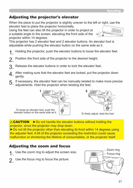
Adjusting the projector's elevator
CAUTION
Adjusting the zoom and focus
14°
51
22
Operating
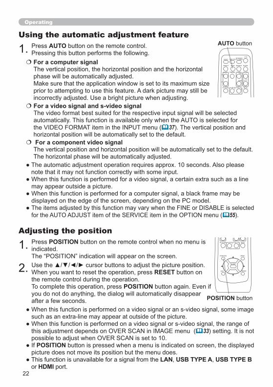
POSITIONAdjusting the position
RESET
POSITION
33
POSITION
LAN USB TYPE A USB TYPE BHDMI
AUTOUsing the automatic adjustment feature
For a computer signal
For a video signal and s-video signal
37
55
POSITION
KEYSTONE MUTEMY BUTTON
POSITION
1 2
ESC
ENTER
MENU
RESET
AUTO
For a component video signal
VIDEO DOC.CAMERA
KEYSTONE
ASPECT SEARCH BLANK
MUTEMY BUTTON1 2
COMPUTERMY SOURCE/
AUTO
MAGNIFY PAGE UP
VOLUME
DOWN
ON
OFF
FREEZE
23
Operating
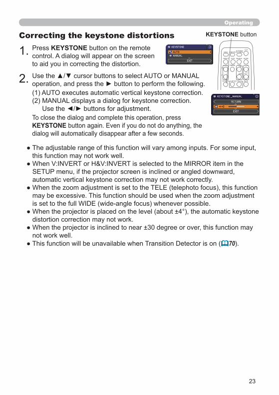
KEYSTONE
Correcting the keystone distortions
KEYSTONE
70
KEYSTONE
VIDEO DOC.CAMERA
KEYSTONE
ASPECT SEARCH BLANK
MUTEMY BUTTON1 2
COMPUTERMY SOURCE/
AUTO
MAGNIFY PAGE UP
VOLUME
DOWN
ON
OFF
FREEZE
24
Operating
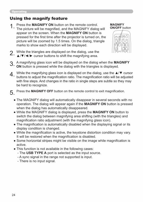
Using the magnify featureMAGNIFYON/OFF
VIDEO DOC.CAMERA
KEYSTONE
ASPECT SEARCH BLANK
MUTEMY BUTTON1 2
COMPUTERMY SOURCE/
AUTO
MAGNIFY PAGE UP
VOLUME
DOWN
ON
OFF
FREEZE
MAGNIFY ON
MAGNIFY ON
MAGNIFY ON
MAGNIFY OFF
MAGNIFY ON
MAGNIFY ON
USB TYPE A
25
Operating
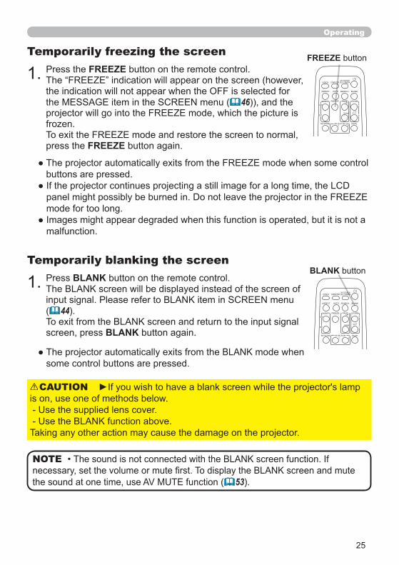
BLANK
( 44
BLANK
Temporarily blanking the screen
( 53
NOTE
FREEZE
46
FREEZE
Temporarily freezing the screen FREEZE
VIDEO DOC.CAMERA
KEYSTONE
ASPECT SEARCH BLANK
MUTEMY BUTTON1 2
COMPUTERMY SOURCE/
AUTO
MAGNIFY PAGE UP
VOLUME
DOWN
ON
OFF
FREEZE
BLANK
VIDEO DOC.CAMERA
KEYSTONE
ASPECT SEARCH BLANK
MUTEMY BUTTON1 2
COMPUTERMY SOURCE/
AUTO
MAGNIFY PAGE UP
VOLUME
DOWN
ON
OFF
FREEZE
CAUTION
26
Operating
MENU
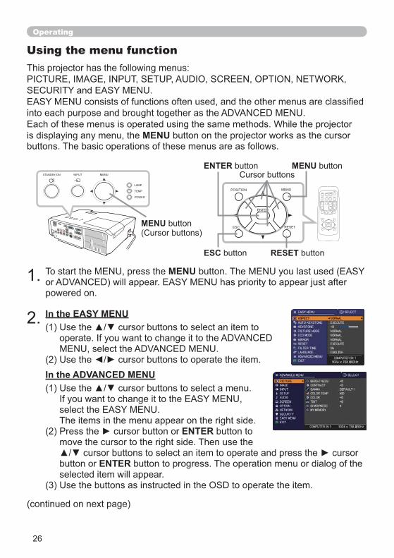
Using the menu function
MENU
In the EASY MENU
MENU
VIDEO DOC.CAMERA
KEYSTONE
ASPECT SEARCH BLANK
MUTEMY BUTTON
POSITION
1 2
ESC
ENTER
MENU
RESET
COMPUTERMY SOURCE/
AUTO
MAGNIFY PAGE UP
VOLUME
DOWN
ON
OFF
FREEZE
RESET
ENTER MENU
POSITION
ESC
ENTER
MENU
RESET
ESC
ENTER
ENTER
In the ADVANCED MENU
27
Operating
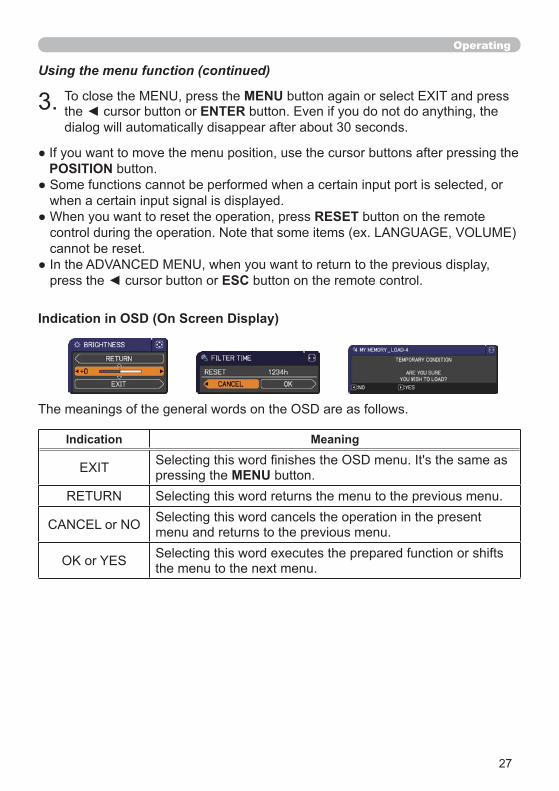
Using the menu function (continued)
MENUENTER
POSITION
RESET
ESC
Indication in OSD (On Screen Display)
Indication Meaning
MENU
28
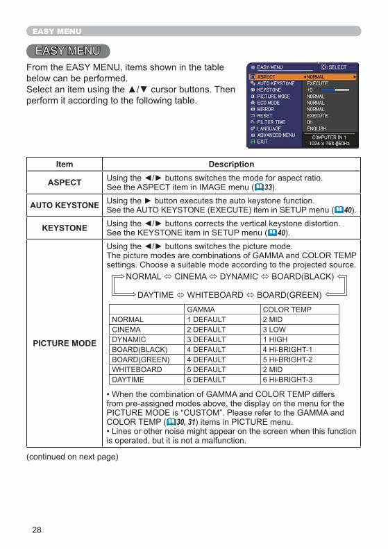
EASY MENU
Item Description
ASPECT 33
AUTO KEYSTONE 40
KEYSTONE 40
PICTURE MODE
30, 31
29
EASY MENU
Item Description
ECO MODE 41
MIRROR 41
RESET
FILTER TIME
52
LANGUAGE 44
ADVANCED MENUENTER
EXIT ENTER
30
PICTURE menu
ENTER
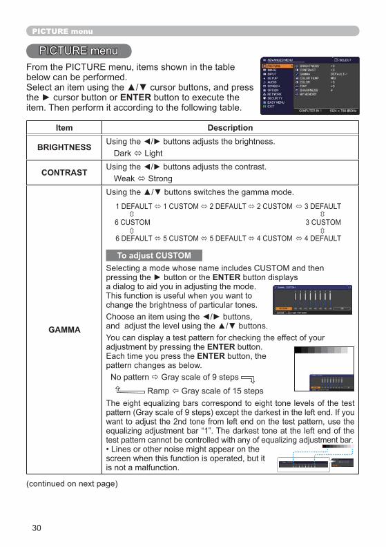
Item Description
BRIGHTNESS
CONTRAST
GAMMA
To adjust CUSTOM
ENTER
ENTERENTER
1 DEFAULT 1 CUSTOM 2 DEFAULT 2 CUSTOM 3 DEFAULT
6 CUSTOM 3 CUSTOM
6 DEFAULT 5 CUSTOM 5 DEFAULT 4 CUSTOM 4 DEFAULT
31
PICTURE menu
Item Description
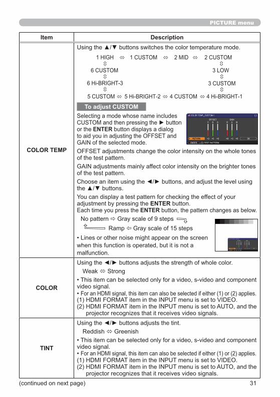
COLOR TEMP
To adjust CUSTOM
ENTER
ENTERENTER
COLOR
TINT
1 HIGH 1 CUSTOM 2 MID 2 CUSTOM
3 LOW
5 CUSTOM 5 Hi-BRIGHT-2 4 CUSTOM 4 Hi-BRIGHT-1
6 CUSTOM
6 Hi-BRIGHT-3 3 CUSTOM
32
PICTURE menu
Item Description
SHARPNESS
MY MEMORY
ENTER
MY BUTTON53
33
IMAGE menu
ENTER
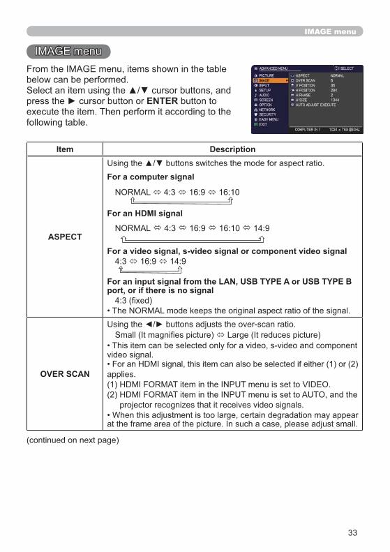
Item Description
ASPECT
For a computer signal
For an HDMI signal
For a video signal, s-video signal or component video signal
For an input signal from the LAN, USB TYPE A or USB TYPE B port, or if there is no signal
OVER SCAN
34
IMAGE menu
Item Description
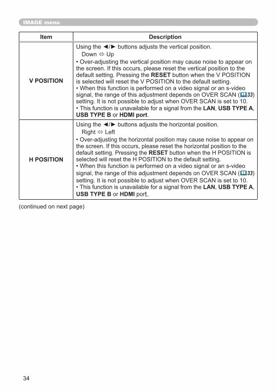
V POSITIONRESET
33
LAN USB TYPE AUSB TYPE B HDMI port
H POSITIONRESET
( 33
LAN USB TYPE AUSB TYPE B HDMI
35
IMAGE menu
Item Description
H PHASE
LAN USB TYPE A USB TYPE B HDMI
H SIZE
LAN USB TYPE A USB TYPE B HDMI
RESET
AUTO ADJUST EXECUTE
For a computer signal
For a video signal and s-video signal
37
For a component video signal
55
36
INPUT menu
ENTER
Item Description
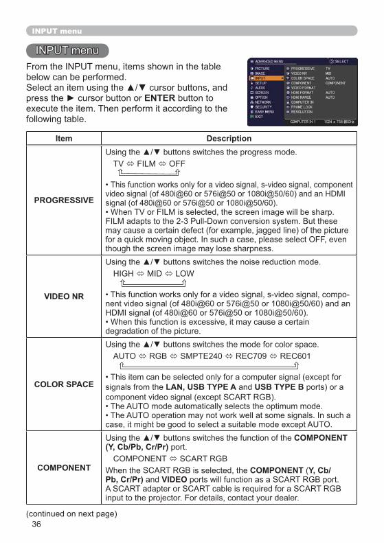
PROGRESSIVE
VIDEO NR
COLOR SPACE LAN, USB TYPE A USB TYPE B
COMPONENT
COMPONENT(Y, Cb/Pb, Cr/Pr)
COMPONENT Y, Cb/Pb, Cr/Pr) VIDEO
37
INPUT menu
Item Description
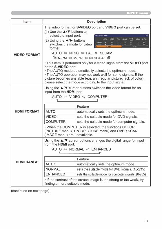
VIDEO FORMAT
S-VIDEO VIDEO
VIDEOS-VIDEO
HDMI FORMAT
HDMI
HDMI RANGE
HDMI
38
INPUT menu
Item Description
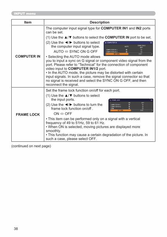
COMPUTER IN
COMPUTER IN1 IN2
COMPUTER IN
COMPUTER IN1/2
FRAME LOCK
39
INPUT menu
Item Description
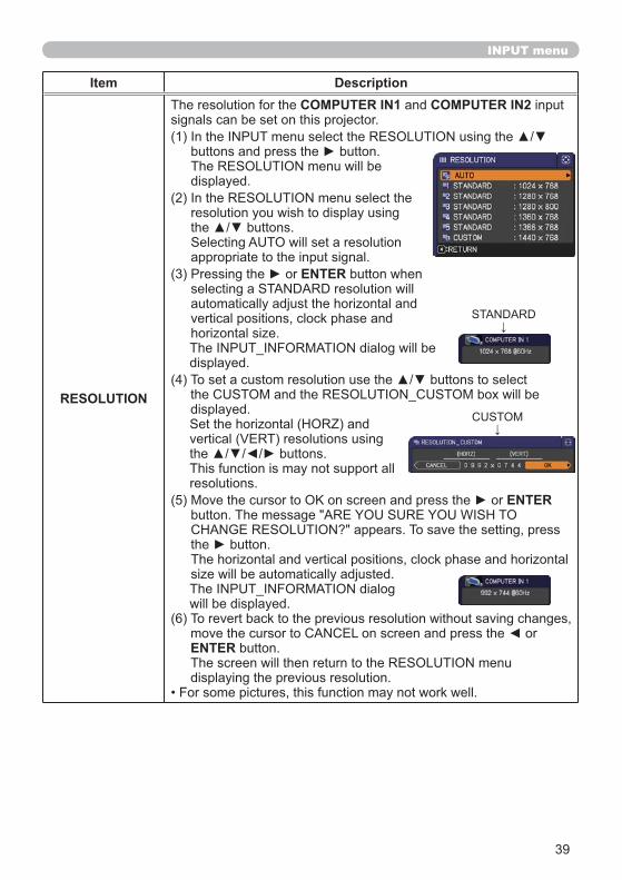
RESOLUTION
COMPUTER IN1 COMPUTER IN2
ENTER
ENTER
ENTER
40
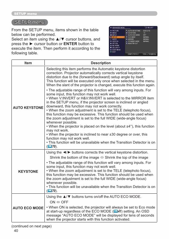
SETUP menu
ENTER
Item Description
AUTO KEYSTONE
( 70
KEYSTONE
( 70
AUTO ECO MODE( 41
41
SETUP menu
Item Description
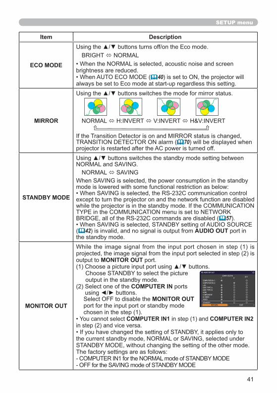
ECO MODE
( 40
MIRROR
( 70
STANDBY MODE
( 57
( 42 AUDIO OUT
MONITOR OUT
MONITOR OUT
COMPUTER IN
MONITOR OUT
COMPUTER IN1 COMPUTER IN2
42
AUDIO menu
ENTER
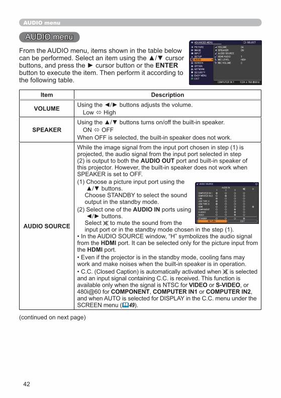
Item Description
VOLUME
SPEAKER
AUDIO SOURCE
AUDIO OUT
AUDIO IN
HDMIHDMI
VIDEO S-VIDEOCOMPONENT COMPUTER IN1 COMPUTER IN2
( 49
43
AUDIO menu
Item Description
HDMI AUDIO
MIC LEVELMIC
MIC VOLUME MIC
44
SCREEN menu
ENTER
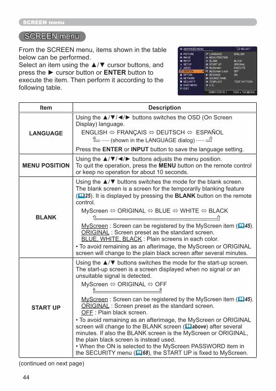
Item Description
LANGUAGE
ENTER INPUT
MENU POSITION MENU
BLANK
( 25 BLANK
45
START UP45
OFF
( above
( 68
45
SCREEN menu
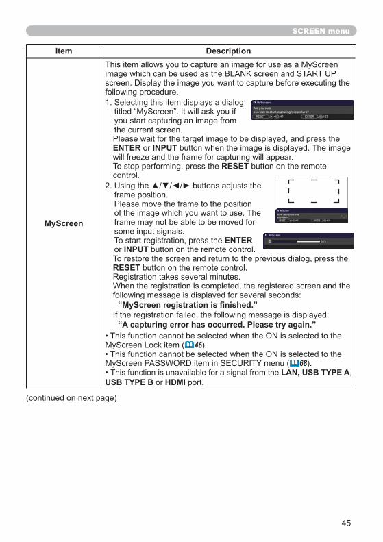
Item Description
MyScreen
ENTER INPUT
RESET
ENTERINPUT
RESET
( 46
( 68LAN, USB TYPE A
USB TYPE B HDMI
46
SCREEN menu
Item Description
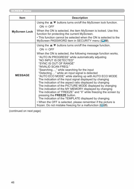
MyScreen Lock
( 68
MESSAGE
FREEZE
( 25
47
SCREEN menu
Item Description
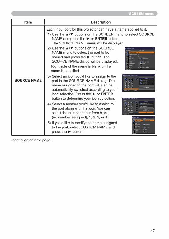
SOURCE NAME
ENTER
ENTER
48
SCREEN menu
Item Description
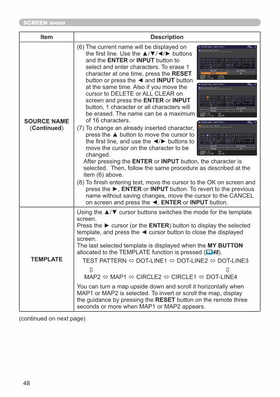
SOURCE NAME(Continued
ENTER INPUT
RESETINPUT
ENTER INPUT
ENTER INPUT
ENTER INPUT
ENTER INPUT
TEMPLATE
ENTER
MY BUTTON( 48
RESET
49
SCREEN menu
Item Description
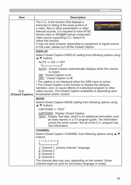
C.C.(Closed Caption)
DISPLAY
OFF
MODE
CHANNEL
1234
50
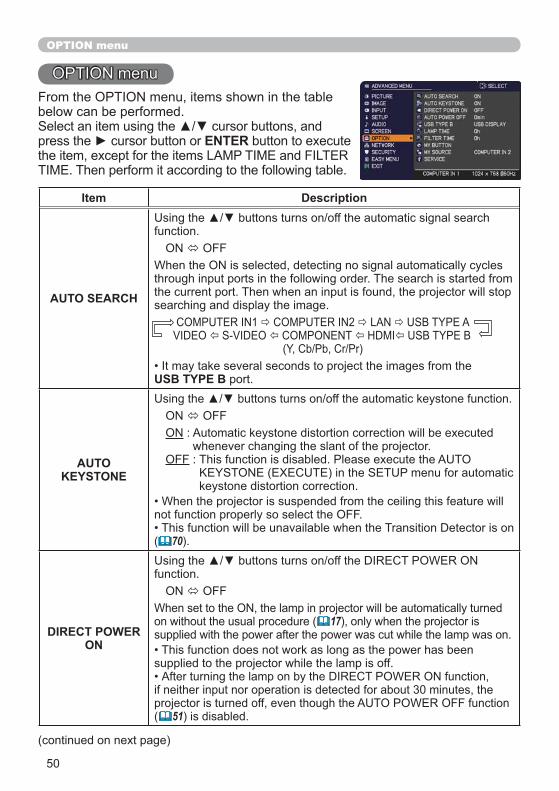
OPTION menu
ENTER
Item Description
AUTO SEARCH
USB TYPE B
AUTO KEYSTONE
OFF
( 70
DIRECT POWER ON
( 17
( 51
51
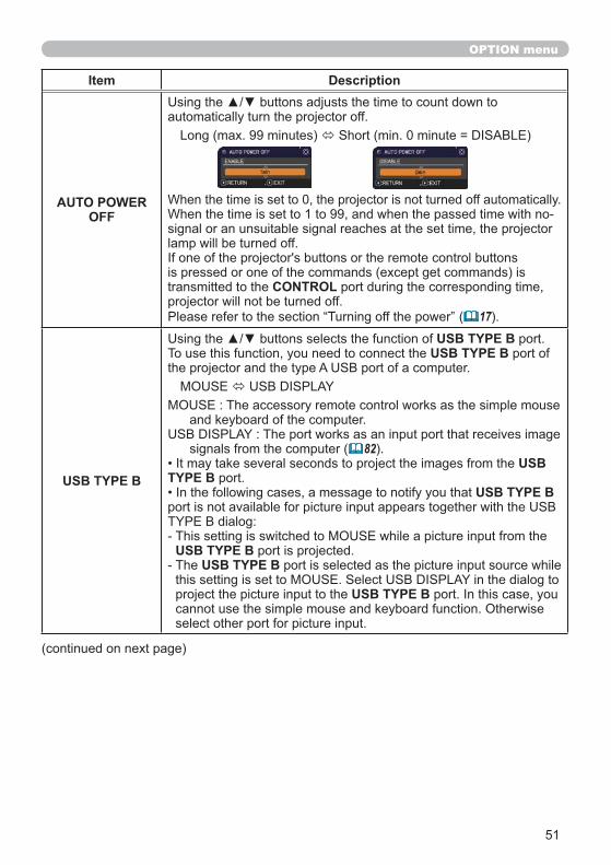
OPTION menu
Item Description
AUTO POWER OFF
CONTROL
( 17
USB TYPE B
USB TYPE BUSB TYPE B
( 82USB
TYPE BUSB TYPE B
USB TYPE BUSB TYPE B
USB TYPE B
52
OPTION menu
Item Description
LAMP TIME
RESET
85
FILTER TIME
RESET
( 87, 88
53
OPTION menu
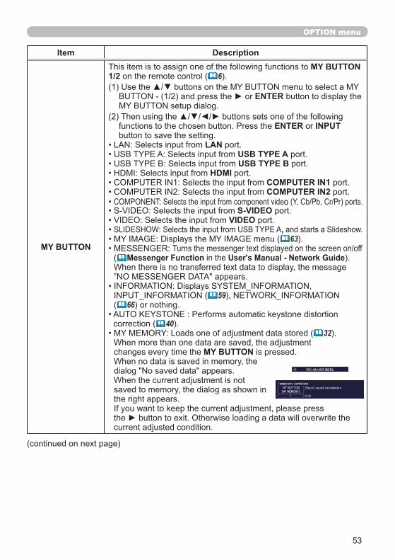
Item Description
MY BUTTON
MY BUTTON 1/2 ( 6
ENTER
ENTER INPUT
LANUSB TYPE AUSB TYPE B
HDMICOMPUTER IN1 COMPUTER IN2
S-VIDEOVIDEO
,( 63
( Messenger Function User's Manual - Network Guide
( 59( 66
( 40( 32
MY BUTTON
54
OPTION menu
Item Description
MY BUTTON(Continued
( 28( 52
( 48
( 39( 43
( 41
MY SOURCE
MY SOURCE/DOC.CAMERA
55
OPTION menu
Item Description
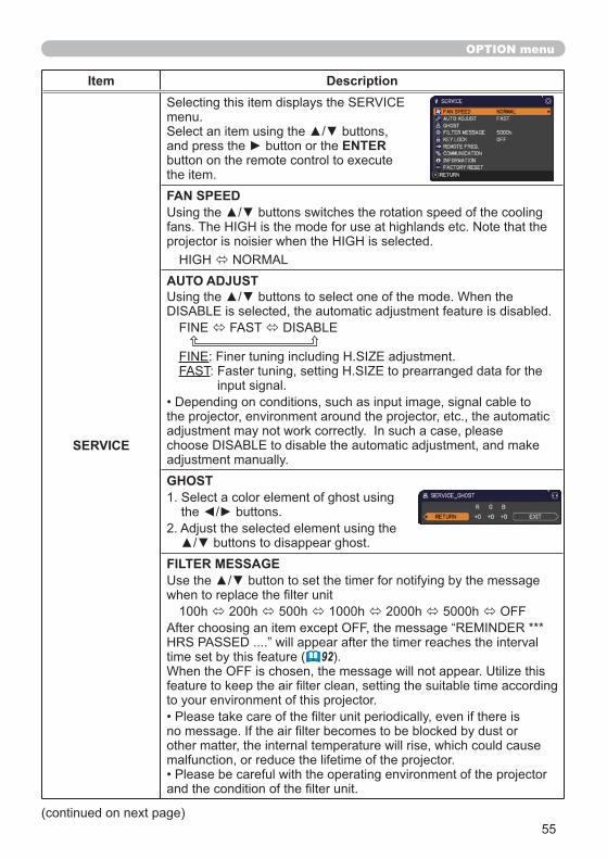
SERVICE
ENTER
FAN SPEED
AUTO ADJUST
GHOST
FILTER MESSAGE
92
56
OPTION menu
Item Description
SERVICE(continued)
KEY LOCK
STANDBY/ON
REMOTE FREQ.
( 4, 16
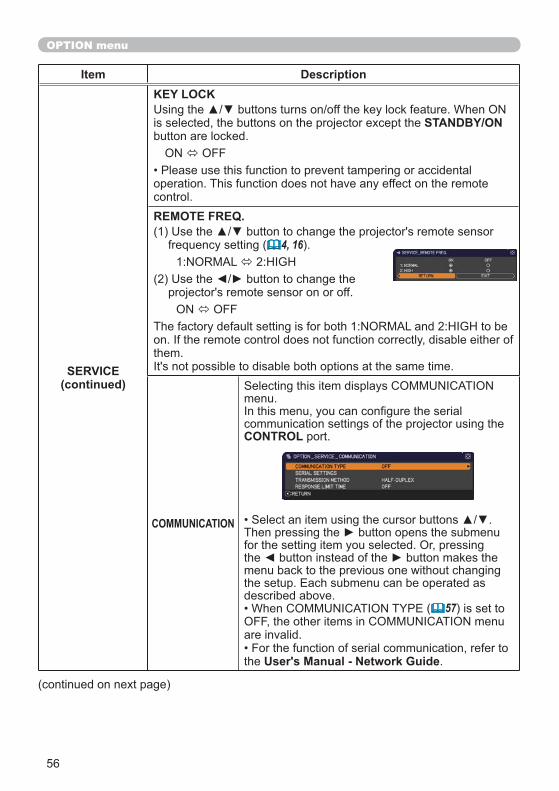
COMMUNICATION
CONTROL
( 57
User's Manual - Network Guide
57
OPTION menu
Item Description
SERVICE(continued)
COMMUNICATION(continued)
COMMUNICATION TYPE
CONTROLOFF
CONTROLNetwork Bridge Function
User’s Manual - Network GuideOFF
CONTROL
( belowSERIAL SETTINGS
CONTROLBAUD RATE
PARITY
( aboveTRANSMISSION METHOD
CONTROL
( 58
58
OPTION menu
Item Description
SERVICE(continued)
COMMUNICATION(continued)
RESPONSE LIMIT TIME
CONTROL
OFF
CONTROL
( 57
59
OPTION menu
Item Description
SERVICE(continued)
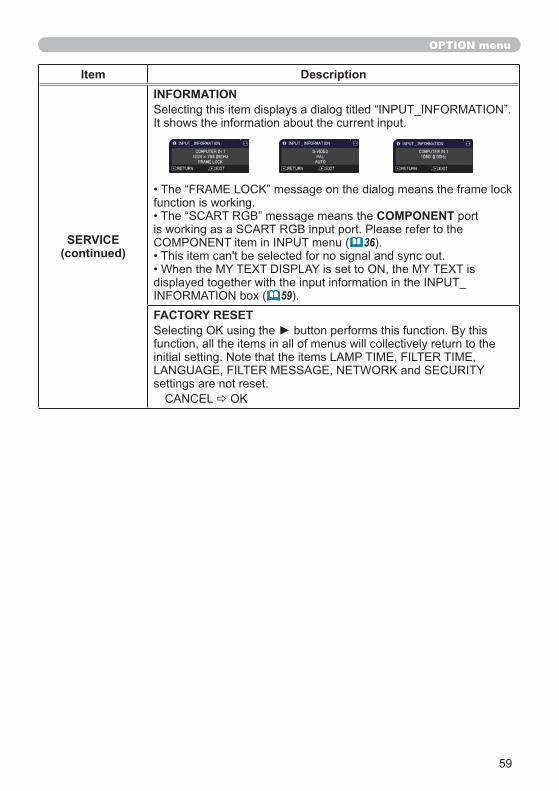
INFORMATION
COMPONENT
36
59FACTORY RESET
60
NETWORK menu
ENTER
User’s Manual - Network Guide
( Date/Time Settings User’s Manual - Network Guide)
( 41
NOTE
Item Description
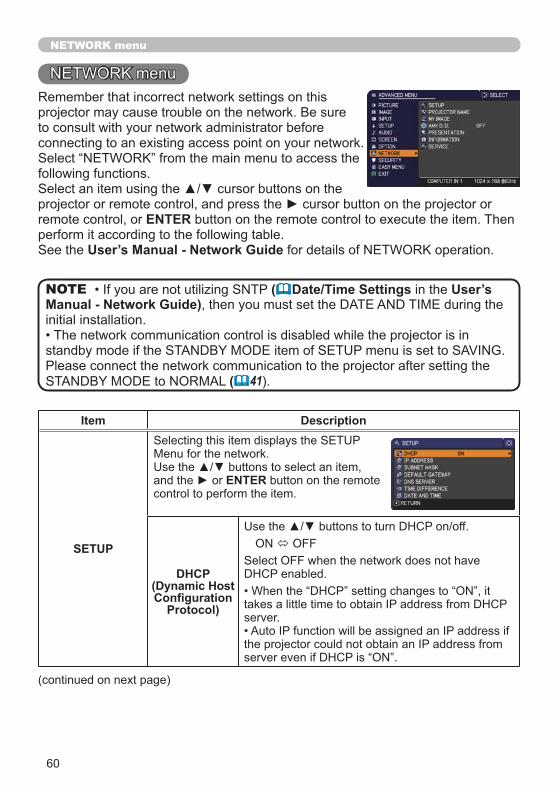
SETUP
ENTER
DHCP (Dynamic Host
Protocol)
61
NETWORK menu
Item Description
SETUP
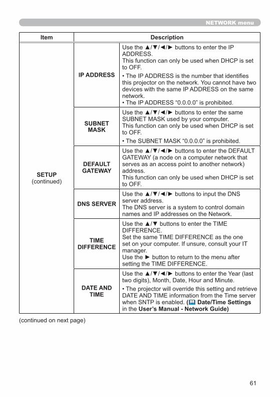
IP ADDRESS
SUBNETMASK
DEFAULT GATEWAY
DNS SERVER
TIMEDIFFERENCE
DATE AND TIME
( Date/Time Settings User’s Manual - Network Guide)

62
NETWORK menu
Item Description
PROJECTOR NAME
ENTER INPUT
RESETINPUT
ENTER INPUT
ENTER INPUT
ENTER INPUT
ENTER INPUT
63
NETWORK menu
Item Description
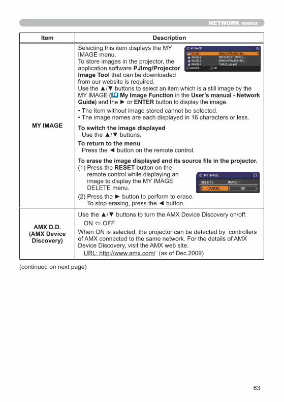
MY IMAGE
PJImg/ProjectorImage Tool
( My Image Function User’s manual - Network Guide) ENTER
To switch the image displayed
To return to the menu
RESET
AMX D.D.(AMX Device Discovery)
64
NETWORK menu
Item Description
PRESENTATION
ENTER
QUITPRESENTER
MODE
Presenter modeUser's Manual – Network Guide
MULTI PC MODE
65
NETWORK menu
Item Description
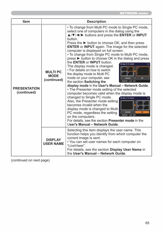
PRESENTATION(continued)
MULTI PC MODE
(continued)
ENTER INPUT
ENTER INPUT
ENTER INPUT
Switching the display mode User's Manual – Network Guide
Presenter modeser's Manual – Network Guide
DISPLAY USER NAME
Display User NameUser's Manual – Network Guide
66
NETWORK menu
Item Description
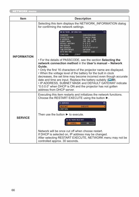
INFORMATIONSelecting the
network connection method User’s manual – Network Guide.
89
SERVICE
67
SECURITY menu
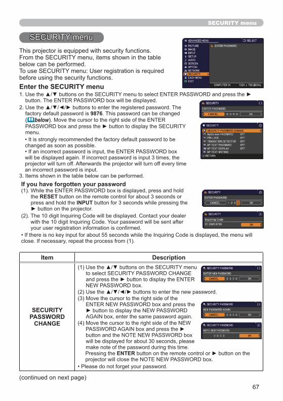
Enter the SECURITY menu
9876( below
If you have forgotten your password
RESETINPUT
Item Description
SECURITY PASSWORD
CHANGE
ENTER

68
SECURITY menu
Item Description
MyScreenPASSWORD
1 Turning on the MyScreen PASSWORD
ENTER
2 Turning off the MyScreen PASSWORD
3 If you have forgotten your password
69
SECURITY menu
Item Description
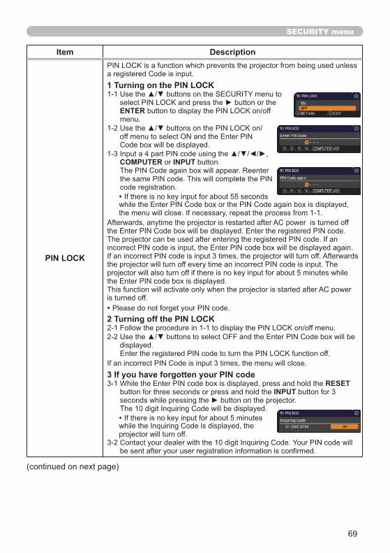
PIN LOCK
1 Turning on the PIN LOCK
ENTER
COMPUTER INPUT
2 Turning off the PIN LOCK
3 If you have forgotten your PIN codeRESET
INPUT
70
SECURITY menu
Item Description
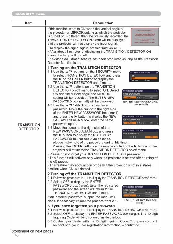
TRANSITIONDETECTOR
1 Turning on the TRANSITION DETECTOR
ENTER
ENTER
2 Turning off the TRANSITION DETECTOR
3 If you have forgotten your password
71
SECURITY menu
Item Description
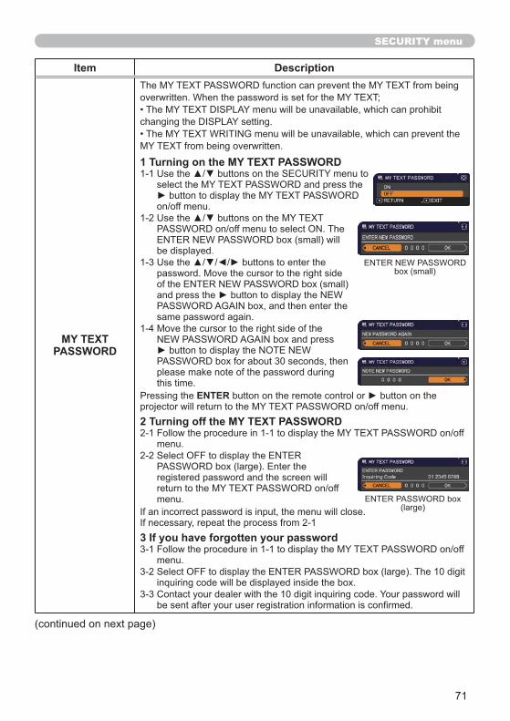
MY TEXT PASSWORD
1 Turning on the MY TEXT PASSWORD
ENTER
2 Turning off the MY TEXT PASSWORD
3 If you have forgotten your password
72
SECURITY menu
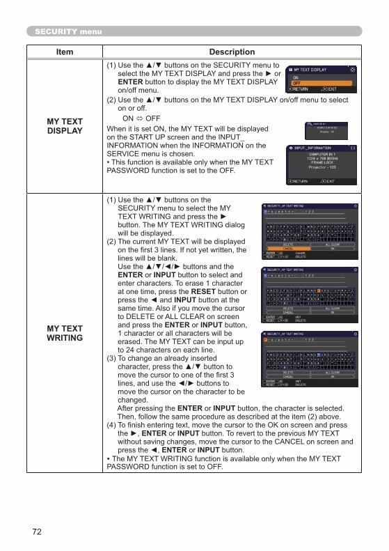
Item Description
MY TEXT DISPLAY
ENTER
MY TEXT WRITING
ENTER INPUT
RESETINPUT
ENTER INPUT
ENTER INPUT
ENTER INPUT
ENTER INPUT
73
Presentation tools
USB TYPE AUSB TYPE A
PC-LESS Presentation
7478
79
[Supported storage media]
12, 76
NOTE
NOTE
NOTE
[Supported format]
below82
74
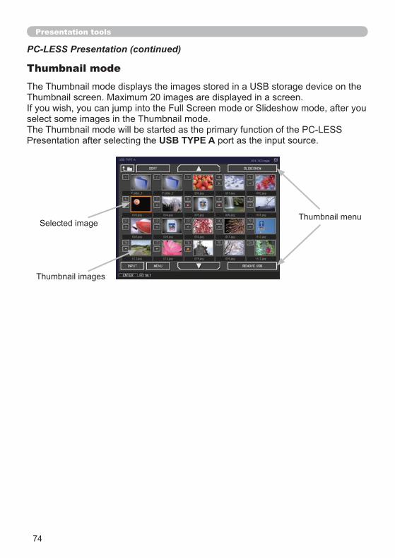
Presentation tools
Thumbnail mode
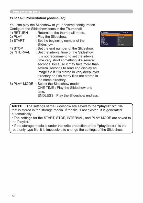
PC-LESS Presentation (continued)
USB TYPE A
75
Presentation tools
PC-LESS Presentation (continued)
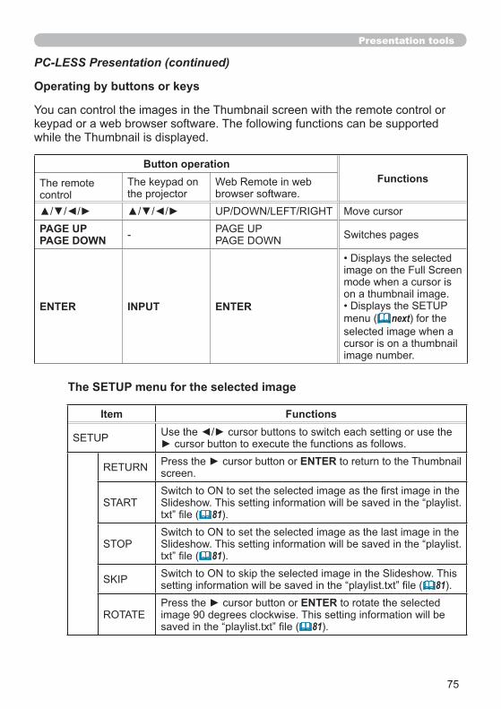
The SETUP menu for the selected image
Item Functions
ENTER
” ( 81
” ( 81
” ( 81ENTER
” ( 81
Operating by buttons or keys
Button operationFunctions
PAGE UPPAGE DOWN
ENTER INPUT ENTER( next
76
Presentation tools
PC-LESS Presentation (continued)
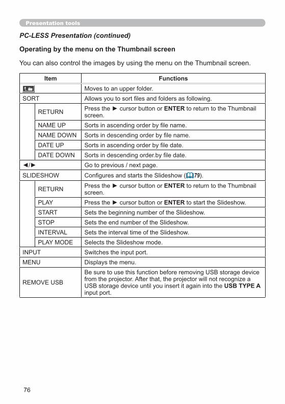
Operating by the menu on the Thumbnail screen
Item Functions
ENTER
( 79ENTER
ENTER
USB TYPE A
77
Presentation tools
PC-LESS Presentation (continued)
INPUT
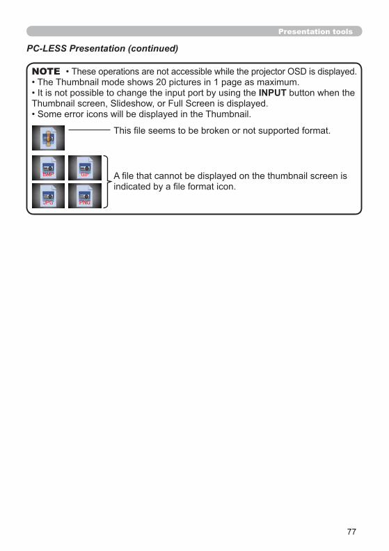
NOTE
78
Presentation tools
PC-LESS Presentation (continued)
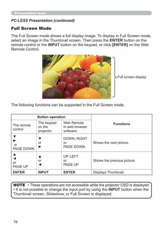
ENTERINPUT [ENTER]
Full Screen Mode
Button operation
Functions
ENTER INPUT ENTER
INPUTNOTE
79
Presentation tools
PC-LESS Presentation (continued)
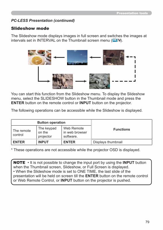
Slideshow mode
INPUT
ENTERINPUT
NOTE
ENTER INPUT
Button operation
Functions
ENTER INPUT ENTER
74
80
Presentation tools
PC-LESS Presentation (continued)
NOTE
81
Presentation tools
PC-LESS Presentation (continued)
Playlist
[Example of playlist.txt”
80
79
NOTE
82
Presentation tools
USB Display10
USB TYPE B
NOTE
Hardware and software requirement for computerOS
®
®
CPUGraphic cardMemoryHard disk spaceUSB PortUSB cable
User's Manual - Network GuideNOTE
83
Presentation tools
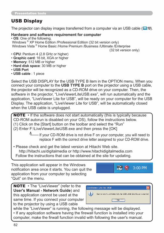
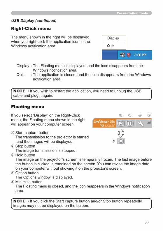
USB Display (continued)
Right-Click menu
Floating menu
NOTE
NOTE
84
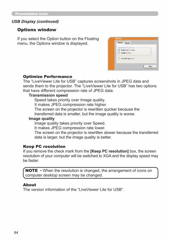
Presentation tools
Optimize Performance
Transmission speed
Image quality
Keep PC resolution[Keep PC resolution]
USB Display (continued)
Options window
About
NOTE
85
Maintenance
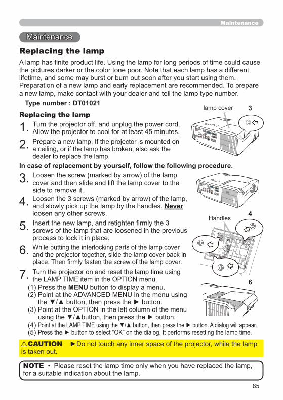
Replacing the lamp
Type number : DT01021
Never
In case of replacement by yourself, follow the following procedure.
Replacing the lamp
NOTE
CAUTION
4
3
6MENU

86
Maintenance
Lamp warning
Replacing the lamp (continued)
HIGH VOLTAGE HIGH TEMPERATURE HIGH PRESSURE
About disposal of a lamp:
WARNING

87
Maintenance
Type number : MU06481
2
4
3
7
88
Maintenance
WARNING
NOTE
MENU
89
Maintenance
WARNING
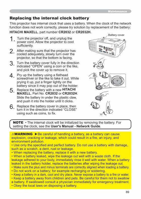
Replacing the internal clock battery
HITACHI MAXELL CR2032 CR2032H.
NOTE User's Manual - Network Guide
HITACHI MAXELL CR2032 CR2032H
OPEN
CLOS
E
OPEN
CLOS
E
OPENCLOSE
90°
OPEN
CLOS
E
90°
90
Maintenance
Other care
WARNING
NOTICE
CAUTION
Inside of the projector
Caring for the lens
Caring for the cabinet and remote control
91
TroubleshootingWARNING
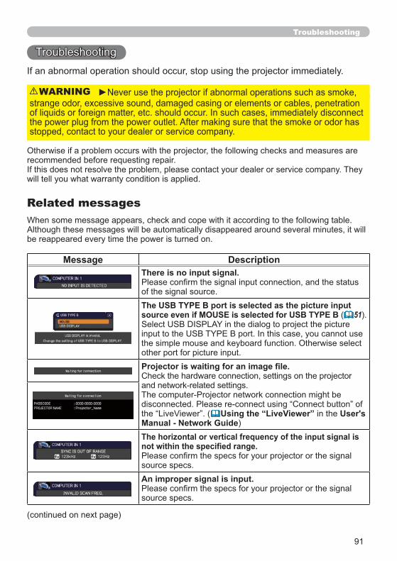
Related messages
Message DescriptionThere is no input signal.
The USB TYPE B port is selected as the picture input source even if MOUSE is selected for USB TYPE B ( 51
( User'sManual - Network GuideThe horizontal or vertical frequency of the input signal is
An improper signal is input.
Troubleshooting
92
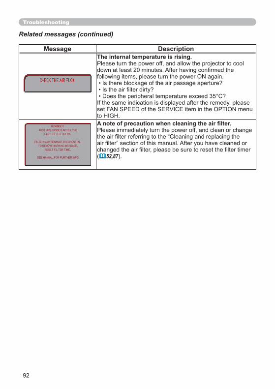
Message DescriptionThe internal temperature is rising.
( 52,87
Troubleshooting
Related messages (continued)
93
Troubleshooting
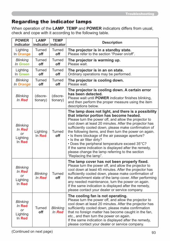
Regarding the indicator lampsLAMP TEMP POWER
POWERindicator
LAMP indicator
TEMP indicator Description
Orange off offThe projector is in a standby state.
BlinkingIn Green off off
The projector is warming up.
Green off offThe projector is in an on state.
BlinkingIn Orange off off
The projector is cooling down.
BlinkingIn Red
The projector is cooling down. A certain error has been detected.
POWER
BlinkingIn Red
or
RedRed off
The lamp does not light, and there is a possibility that interior portion has become heated.
BlinkingIn Red
or
Red
BlinkingIn Red off
BlinkingIn Red
or
Redoff
BlinkingIn Red
The cooling fan is not operating.
94
HDMIUSBTYPE B
Troubleshooting
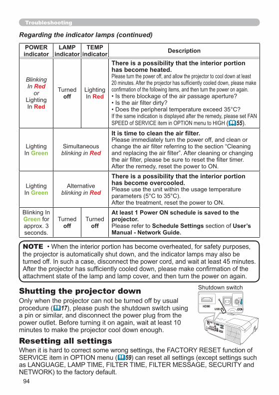
Regarding the indicator lamps (continued)
NOTE
POWERindicator
LAMP indicator
TEMP indicator Description
BlinkingIn Red
or
Redoff Red
There is a possibility that the interior portion has become heated.
( 55
Green blinking in Red
Green blinking in Red
There is a possibility that the interior portion has become overcooled.
Greenoff off
At least 1 Power ON schedule is saved to the projector.
Schedule Settings User’s Manual - Network Guide.
Shutting the projector down
17
Resetting all settings
59

95
Troubleshooting
Phenomena that may be easy to be mistaken for machine defects
Phenomenon Cases not involving a machine defect Referencepage
The electrical power cord is not plugged in. 14
The main power source has been interrupted during operation such as by a power outage (blackout), etc.
Either there is no lamp and/or lamp cover, or either
85
The signal cables are not correctly connected. ~
Signal source does not correctly work.–
The input changeover settings are mismatched. ~
The BLANK function for pictures and the MUTE function for sounds are working.
54
96
Troubleshooting
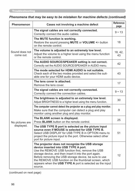
Phenomena that may be easy to be mistaken for machine defects (continued)
Phenomenon Cases not involving a machine defect Referencepage
The signal cables are not correctly connected. ~
The MUTE function is working.MUTE VOLUME + - 18
The volume is adjusted to an extremely low level.
43
The AUDIO SOURCE/SPEAKER setting is not correct. 42
The mode selected for HDMI AUDIO is not suitable.43
The lens cover is attached. 17
The signal cables are not correctly connected. ~
The brightness is adjusted to an extremely low level. 30
The computer cannot detect the projector as a plug and play monitor.9
The BLANK screen is displayed.BLANK 25
The USB TYPE B port is selected as the picture input source even if MOUSE is selected for USB TYPE B.
51
The projector does not recognize the USB storage device inserted into USB TYPE A port.
USB TYPE A
12
97
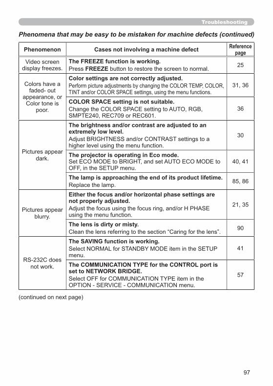
Phenomenon Cases not involving a machine defect Referencepage
The FREEZE function is working.FREEZE 25
Color settings are not correctly adjusted.
COLOR SPACE setting is not suitable.36
The brightness and/or contrast are adjusted to an extremely low level. 30
The projector is operating in Eco mode.
The lamp is approaching the end of its product lifetime.
Either the focus and/or horizontal phase settings are not properly adjusted.
The lens is dirty or misty. 90
The SAVING function is working.41
The COMMUNICATION TYPE for the CONTROL port is set to NETWORK BRIDGE. 57
Troubleshooting
Phenomena that may be easy to be mistaken for machine defects (continued)
98
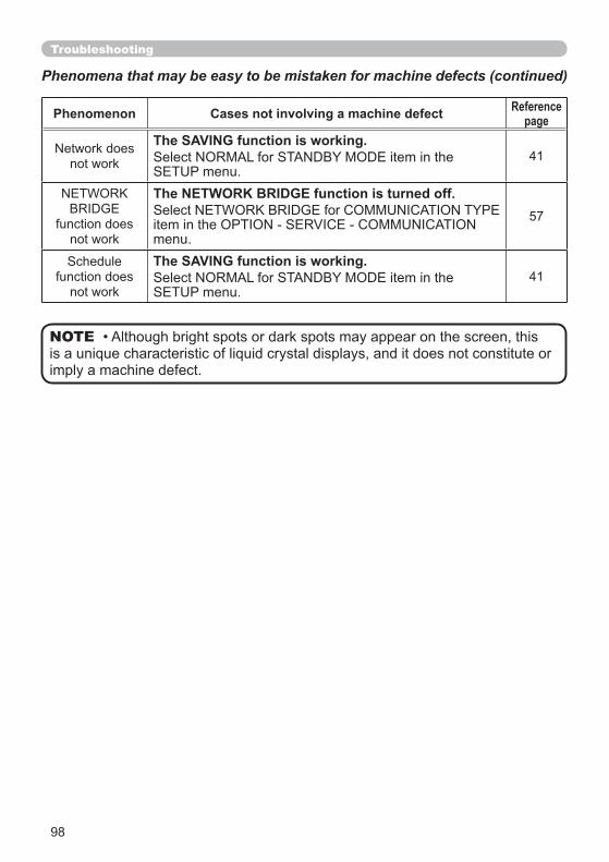
Phenomenon Cases not involving a machine defect Referencepage
The SAVING function is working.41
The NETWORK BRIDGE function is turned off.57
The SAVING function is working.41
Troubleshooting
NOTE
Phenomena that may be easy to be mistaken for machine defects (continued)
99
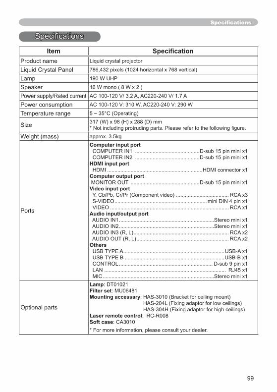
Item
Computer input port
HDMI input port
Computer output port
Video input port
Audio input/output port
Others
LampFilter setMounting accessary
Laser remote controlSoft case
100
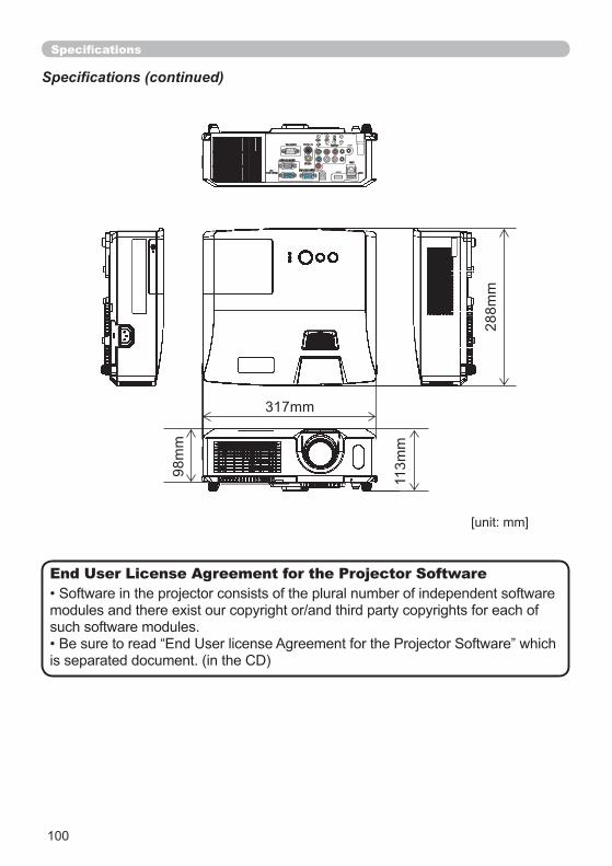
317mm11
3mm
98m
m
288m
m
LAN
MIC
HDMIUSB
IN1
IN2
End User License Agreement for the Projector Software

1
Projector
ED-X45NUser's Manual (detailed) Network Guide
Thank you for purchasing this product.This manual is intended to explain only the network function. For proper use of this product, please refer to this manual and the other manuals for this product.
FeaturesThis projector has the network function that brings you the following main features.
product. After reading them, store them in a safe place for future reference.WARNING
this manual.
permitted without express written consent.
NOTE
Trademark acknowledgment
Network Presentation : allows the projector to project computer images transmitted through a network. ( 37)Web Control : allows you to monitor and control the projector through a network from a computer. ( 45)My Image : allows the projector to store up to four still images and project them. ( 70)Messenger : allows the projector to display text sent from a computer through a network. ( 72)Network Bridge : allows you to control an external device through the projector from a computer. ( 74)
All other trademarks are the properties of their respective owners.
2
Contents
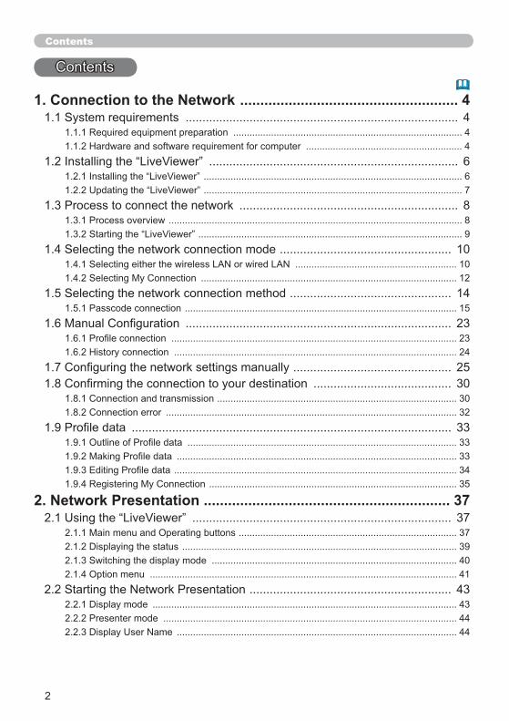
1. Connection to the Network ...................................................... 4................................................................................. 4
..................................................................................... 4.......................................................... 4
.......................................................................... 6................................................................................................ 6................................................................................................ 7
................................................................. 8............................................................................................................. 8
.................................................................................................. 9................................................... 10
............................................................ 10............................................................................................... 12
................................................ 14..................................................................................................... 15............................................................................... 23
.......................................................................................................... 23......................................................................................................... 24
............................................... 25......................................... 30
......................................................................................... 30............................................................................................................ 32
............................................................................................... 33.................................................................................................... 33
........................................................................................................ 33......................................................................................................... 34
............................................................................................ 35
2. Network Presentation ............................................................. 37............................................................................. 37
................................................................................. 37...................................................................................................... 39
........................................................................................... 402.1.4 Option menu .................................................................................................................. 41
............................................................ 43................................................................................................................. 43
............................................................................................................. 44........................................................................................................ 44
3
Contents
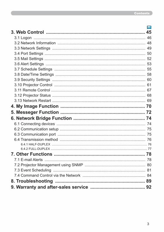
3. Web Control ............................................................................ 45....................................................................................................... 46
................................................................................. 48...................................................................................... 49
............................................................................................. 50
............................................................................................. 52............................................................................................ 53
.................................................................................... 55................................................................................... 58
...................................................................................... 60.................................................................................... 61
....................................................................................... 67...................................................................................... 68...................................................................................... 69
4. My Image Function ................................................................. 705. Messeger Function ................................................................. 726. Network Bridge Function ....................................................... 74
.................................................................................. 74............................................................................... 75
................................................................................. 756.4 Transmission method ............................................................................... 76
.............................................................................................................. 76............................................................................................................... 77
7. Other Functions ...................................................................... 78............................................................................................. 78
........................................................ 80..................................................................................... 81
.......................................................... 848. Troubleshooting ..................................................................... 899. Warranty and after-sales service .......................................... 92
4
1. Connection to the network
1.1 System requirements
through the network.
1.1.1 Required equipment preparation
1.1.2 Hardware and software requirement for computer
ProjectorLAN cable Computer
OS: One of the following.®
®
bit version only)CPUGraphic card
your computer is set to 1024 x 768.MemoryHard disk spaceWeb browser ® 6.0 or higherCD-ROM drive
SETUP menu in the User’s Manual – Operating Guide)
for this product from our website. ( 7)
NOTE
5
1. Connection to the network
1.1 System requirements (continued)
speed will be reduced.
NOTE
6
1.2 Installing the “LiveViewer”
to the projector through a network.
install the software.
1) Turn on the computer.
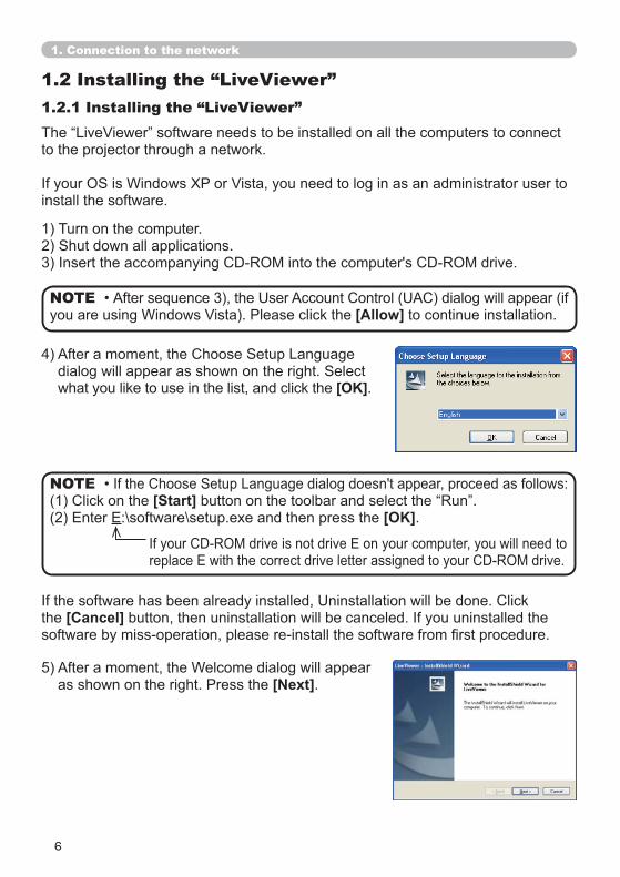
[Start]:\software\setup.exe and then press the [OK].
NOTE
the [Cancel]
[Next].
[Allow] to continue installation. NOTE
what you like to use in the list, and click the [OK].
1. Connection to the network
1.2.1 Installing the “LiveViewer”
7
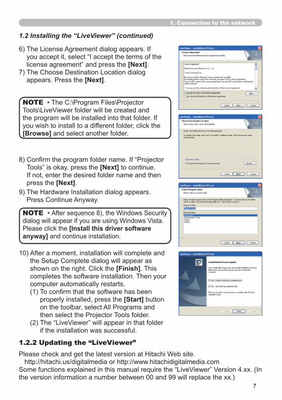
you wish to install to a different folder, click the [Browse] and select another folder.
NOTE
1. Connection to the network
[Next] to continue.
press the [Next].
1.2.2 Updating the “LiveViewer”
the version information a number between 00 and 99 will replace the xx.)
10) After a moment, installation will complete and
[Finish]. This completes the software installation. Then your computer automatically restarts.
properly installed, press the [Start] button
if the installation was successful.
[Install this driver software anyway] and continue installation.
NOTE
1.2 Installing the “LiveViewer” (continued)
[Next].
[Next].
8
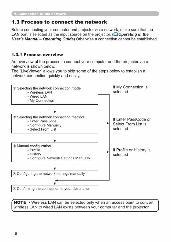
1.3 Process to connect the network
LAN port is selected as the input source on the projector. ( Operating in the User’s Manual – Operating Guide) Otherwise a connection cannot be established.
1.3.1 Process overviewAn overview of the process to connect your computer and the projector via a network is shown below.
1. Connection to the network
NOTE
selected
selected
selected

9
1.3.2 Starting the “LiveViewer”
Then, proceed to item 1.4 Selecting the network connection mode. ( 10)
1.3 Process to connect the network (continued)
1. Connection to the network
10
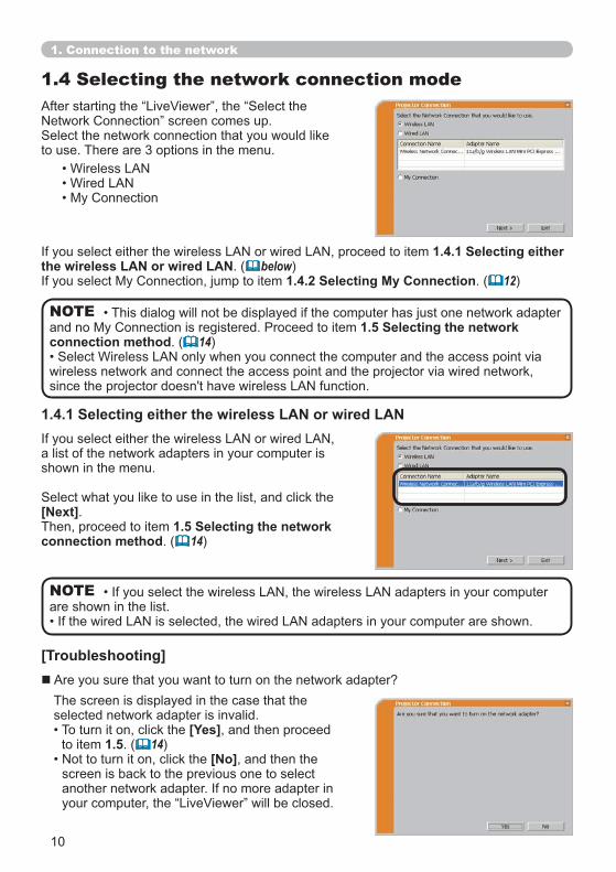
1.4 Selecting the network connection mode
are shown in the list.NOTE
to use. There are 3 options in the menu.
1.4.1 Selecting either the wireless LAN or wired LAN. ( below)
1.4.2 Selecting My Connection. ( 12)
[Troubleshooting]
a list of the network adapters in your computer is shown in the menu.
[Next].Then, proceed to item 1.5 Selecting the network connection method. ( 14)
1.4.1 Selecting either the wireless LAN or wired LAN
Are you sure that you want to turn on the network adapter?The screen is displayed in the case that the selected network adapter is invalid.
[Yes], and then proceed to item 1.5. ( 14)
[No], and then the screen is back to the previous one to select
1. Connection to the network
1.5 Selecting the network connection method. ( 14)
wireless network and connect the access point and the projector via wired network,
NOTE
11
1.4 Selecting the network connection mode (continued)
[Yes]NOTE
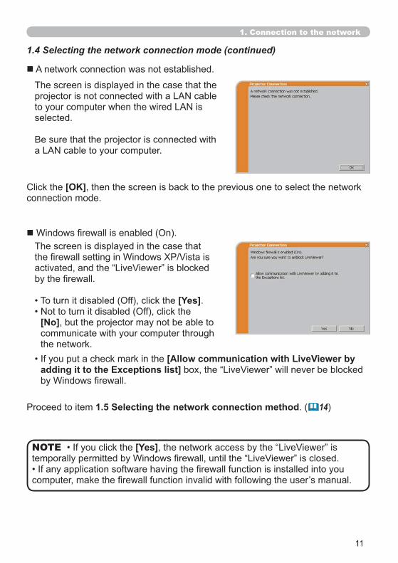
A network connection was not established.
The screen is displayed in the case that the
selected.
[OK], then the screen is back to the previous one to select the network connection mode.
The screen is displayed in the case that
[Yes].
[No], but the projector may not be able to communicate with your computer through the network.
1.5 Selecting the network connection method. ( 14)
[Allow communication with LiveViewer by adding it to the Exceptions list]
1. Connection to the network
12
projector.
NOTE
. ( 30)
[Troubleshooting]
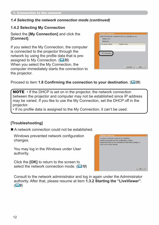
[My Connection] and click the [Connect].
is connected to the projector through the
35)
computer immediately starts the connection to the projector.
1.4.2 Selecting My Connection
A network connection could not be established.
changes.
authority.
[OK] to return to the screen to select the network connection mode. ( 10)
authority. After that, please resume at item 1.3.2 Starting the “LiveViewer”.( 9)
1. Connection to the network
1.4 Selecting the network connection mode (continued)
13
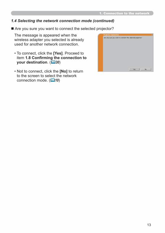
Are you sure you want to connect the selected projector?
The message is appeared when the wireless adapter you selected is already used for another network connection.
[Yes]itemyour destination. ( 30)
[No] to return to the screen to select the network connection mode. ( 10)
1. Connection to the network
1.4 Selecting the network connection mode (continued)
14
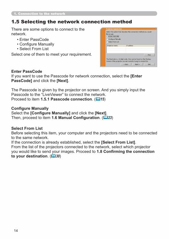
1.5 Selecting the network connection methodThere are some options to connect to the network.
Select From List
to the same network.[Select From List].
From the list of the projectors connected to the network, select which projector
to your destination. ( 30)
Enter PassCode[Enter
PassCode] and click the [Next].
1.5.1 Passcode connection. ( 15)
and click the [Next].Then, proceed to item . ( 23)
1. Connection to the network
15
1.5.1 Passcode connection
network.
and computer can be matched and the connection will be established immediately.
such is the case, establish the connection manually.NOTE
LAN port is selected as input source.
(1) Getting the Passcode
1) Turn on the projector, and make sure that the projector image is on screen.COMPUTER button on the remote control or INPUT button on the
LAN
Method 1
1. Connection to the network
1.5 Selecting the network connection method (continued)
16
1) Turn on the projector, and make sure that the projector image is on screen.MENU
the projector to show the menu on screen.
button to enter the item.
Method 2
LAN port is not selected as input source.NOTE
1. Connection to the network
1.5 Selecting the network connection method (continued)
17
distinguished.
establish the connection manually.1.5.1 (3). ( 21)
NOTE
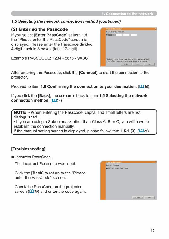
[Enter PassCode] at item 1.5,(2) Entering the Passcode
[Connect] to start the connection to the projector.
. ( 30)
[Back], the screen is back to item 1.5 Selecting the network connection method. ( 14)
[Troubleshooting]
[Back]
screen ( 15) and enter the code again.
1. Connection to the network
1.5 Selecting the network connection method (continued)
18
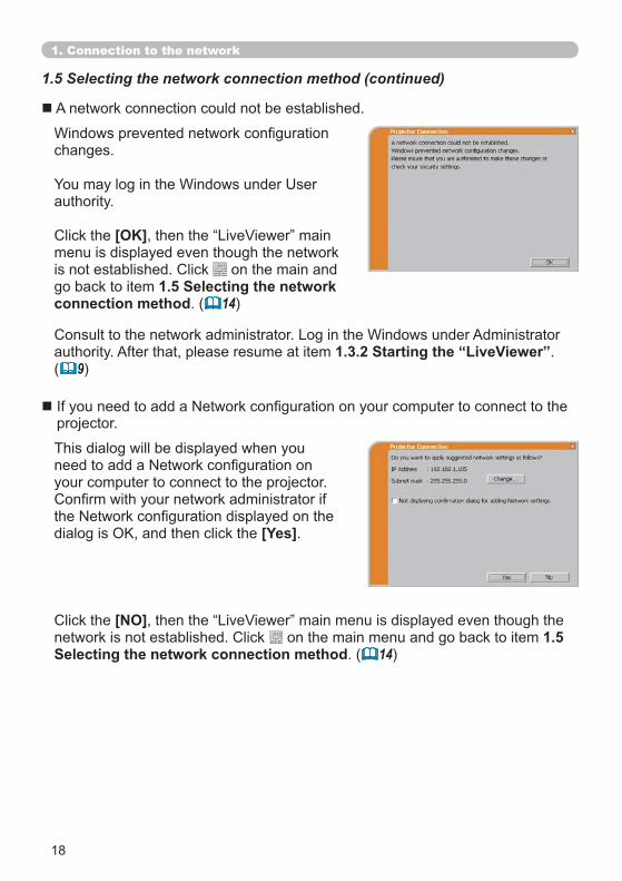
changes.
authority.
[OK]menu is displayed even though the network
on the main and go back to item 1.5 Selecting the network connection method. ( 14)
This dialog will be displayed when you
your computer to connect to the projector.
[Yes].
A network connection could not be established.
projector.
authority. After that, please resume at item 1.3.2 Starting the “LiveViewer”.( 9)
[NO] on the main menu and go back to item 1.5
Selecting the network connection method. ( 14)
1. Connection to the network
1.5 Selecting the network connection method (continued)
19
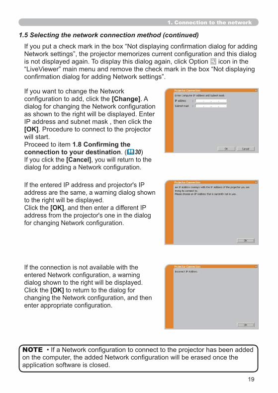
[Change]. A
[OK]will start.
connection to your destination. ( 30)[Cancel], you will return to the
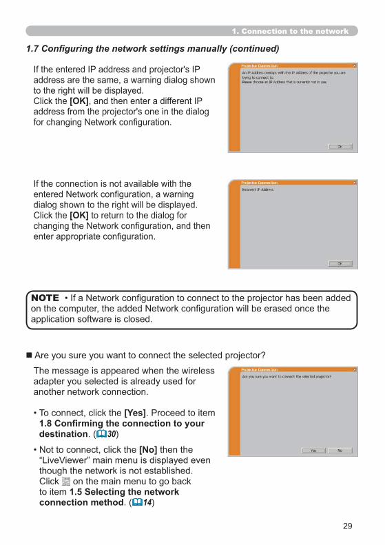
address are the same, a warning dialog shown to the right will be displayed.
[OK]
dialog shown to the right will be displayed.[OK] to return to the dialog for
is not displayed again. To display this dialog again, click Option icon in the
1. Connection to the network
1.5 Selecting the network connection method (continued)
application software is closed.
NOTE
20
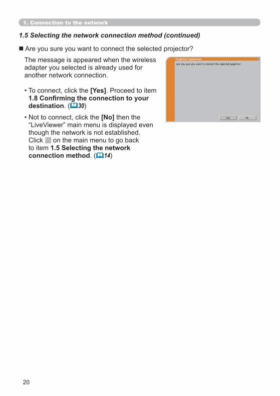
The message is appeared when the wireless adapter you selected is already used for another network connection.
[Yes]
destination. ( 30)
[No] then the
though the network is not established. on the main menu to go back
to item 1.5 Selecting the network connection method. ( 14)
Are you sure you want to connect the selected projector?
1. Connection to the network
1.5 Selecting the network connection method (continued)
21
1715)
22).
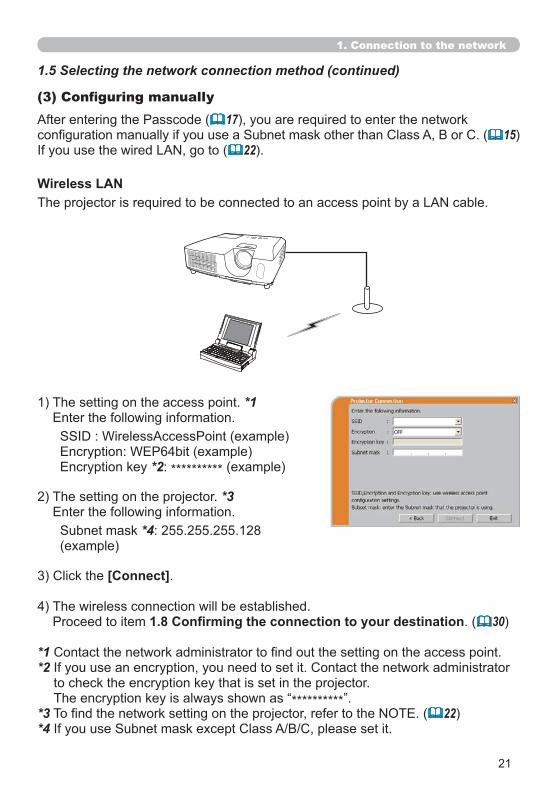
Wireless LAN
1. Connection to the network
1.5 Selecting the network connection method (continued)
*2: ********** (example)
2) The setting on the projector. *3
1) The setting on the access point. *1
[Connect].
4) The wireless connection will be established.. ( 30)
*1*2
to check the encryption key that is set in the projector.**********
*3 22)*4
*4: 255.255.255.128 (example)
22
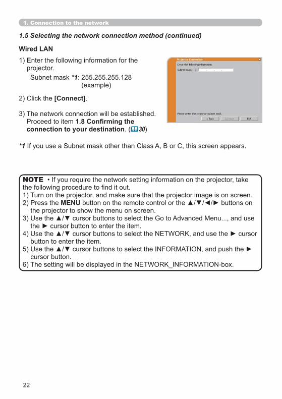
Wired LAN
*1: 255.255.255.128(example)
[Connect].
3) The network connection will be established.
connection to your destination. ( 30)
projector.
*1
1) Turn on the projector, and make sure that the projector image is on screen.MENU
the projector to show the menu on screen.
button to enter the item.
cursor button.
NOTE
1.5 Selecting the network connection method (continued)
1. Connection to the network
23
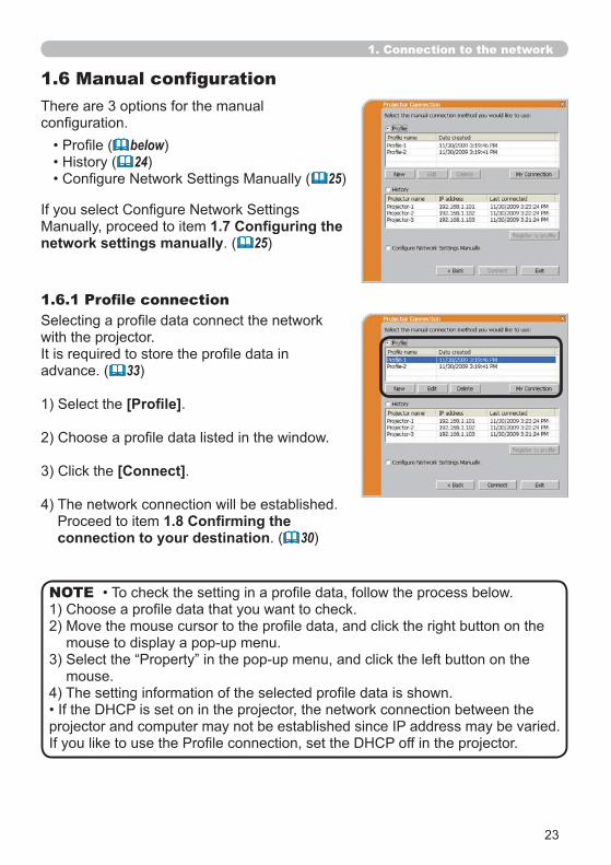
There are 3 options for the manual
network settings manually. ( 25)
below)24)
25)
mouse.
NOTE
with the projector.
advance. ( 33)
.
[Connect].
4) The network connection will be established.
connection to your destination. ( 30)
1. Connection to the network
24
overwritten.
network is connected by using the history record.
varied.
record.
NOTE
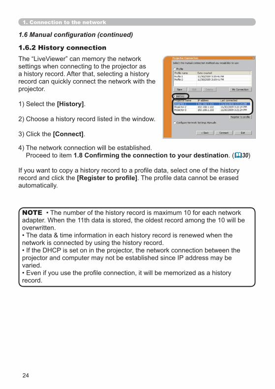
settings when connecting to the projector as a history record. After that, selecting a history
projector.
[History].
[Connect].
1.6.2 History connection
4) The network connection will be established.. ( 30)
record and click the automatically.
1. Connection to the network
25
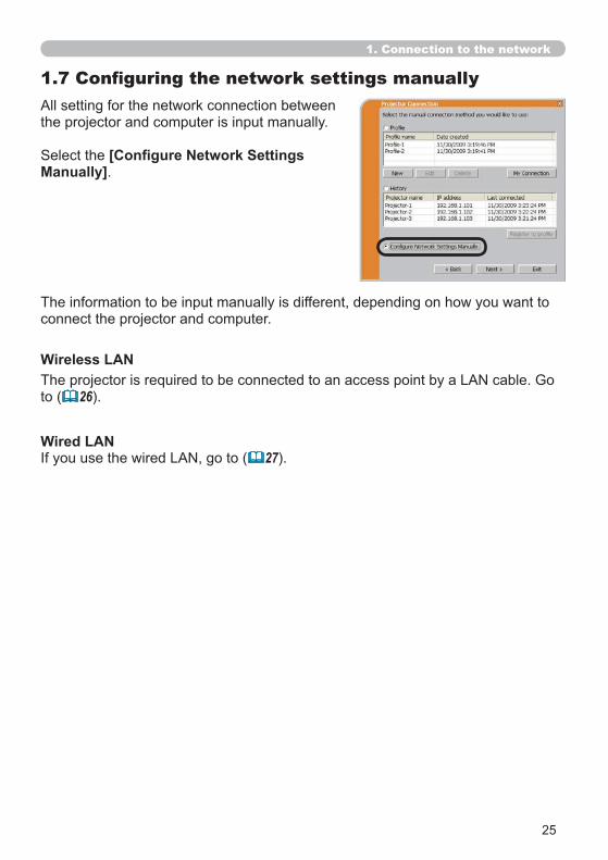
All setting for the network connection between the projector and computer is input manually.
Manually].
The information to be input manually is different, depending on how you want to connect the projector and computer.
27).Wired LAN
to ( 26).
Wireless LAN
1. Connection to the network
26
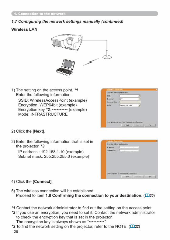
Wireless LAN
*2: ********** (example)
[Next].
the projector. *3
[Connect].
5) The wireless connection will be established.. ( 30)
1) The setting on the access point. *1
*1*2
to check the encryption key that is set in the projector.**********
*3 22)
1. Connection to the network
27
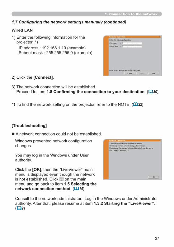
Wired LAN
[Connect].
3) The network connection will be established.. ( 30)
projector. *1
authority. After that, please resume at item 1.3.2 Starting the “LiveViewer”.( 9)
[Troubleshooting]
A network connection could not be established.
changes.
authority.
[OK]menu is displayed even though the network
on the main menu and go back to item 1.5 Selecting the network connection method. ( 14)
*1 22)
1. Connection to the network
28
1. Connection to the network
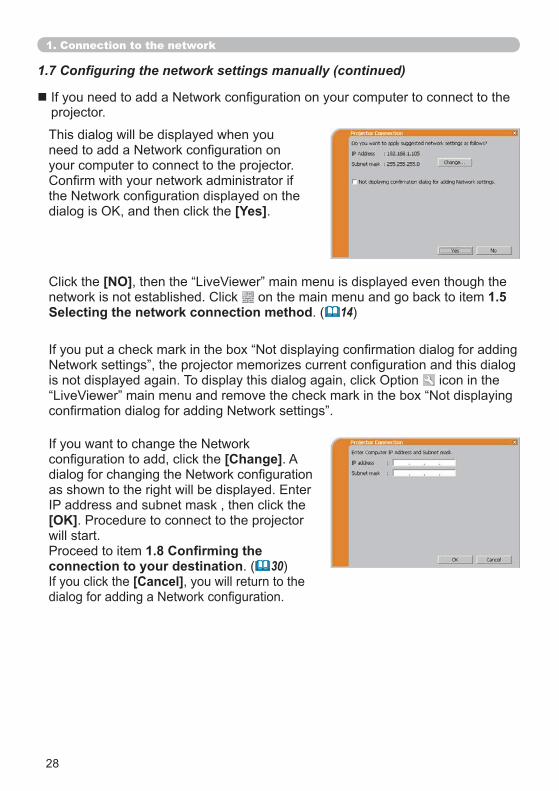
This dialog will be displayed when you
your computer to connect to the projector.
[Yes].
projector.
[NO] on the main menu and go back to item 1.5
Selecting the network connection method. ( 14)
[Change]. A
[OK]will start.
connection to your destination. ( 30)[Cancel], you will return to the
is not displayed again. To display this dialog again, click Option icon in the
29
1. Connection to the network
address are the same, a warning dialog shown to the right will be displayed.
[OK]
dialog shown to the right will be displayed.[OK] to return to the dialog for
application software is closed.
NOTE
The message is appeared when the wireless adapter you selected is already used for another network connection.
[Yes]
destination. ( 30)
[No] then the
though the network is not established. on the main menu to go back
to item 1.5 Selecting the network connection method. ( 14)
Are you sure you want to connect the selected projector?
30
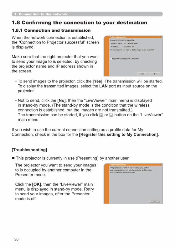
is displayed.
to send your image to is selected, by checking
the screen.
1.8.1 Connection and transmission
To send images to the projector, click the [Yes]. The transmission will be started.To display the transmitted images, select the LAN port as input source on the projector.
the [No]
connection is established, but the images are not transmitted.)The transmission can be started, if you click or main menu.
[Troubleshooting]
The projector you want to send your images to is occupied by another computer in the
the [OK]
mode is off.
the [Register this setting to My Connection].
1. Connection to the network
31
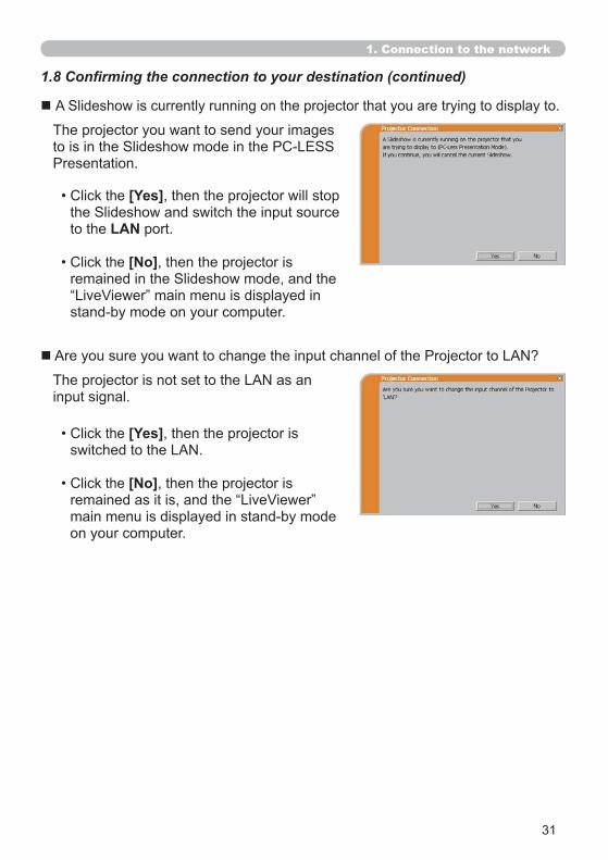
The projector you want to send your images
input signal.
the [Yes], then the projector will stop
to the LAN port.
the [No], then the projector is
the [Yes], then the projector is
the [No], then the projector is
on your computer.
1. Connection to the network
32
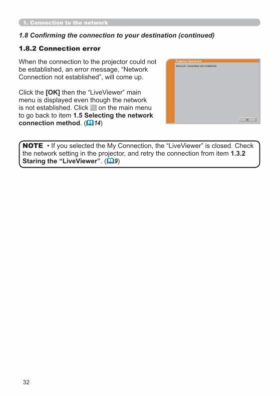
the [OK]menu is displayed even though the network
on the main menu to go back to item 1.5 Selecting the network connection method. ( 14)
1.8.2 Connection error
the network setting in the projector, and retry the connection from item 1.3.2Staring the “LiveViewer”. ( 9)
NOTE
1. Connection to the network
33
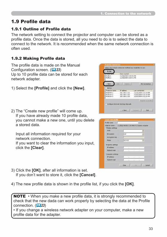
The network setting to connect the projector and computer can be stored as a
often used.
23)
network adapter.
the and click the [New].
you cannot make a new one, until you delete a stored data.
network connection.
click the [Clear].
the [OK], after all information is set. the [Cancel].
the [OK].
connection. ( 23)
NOTE
1. Connection to the network
34
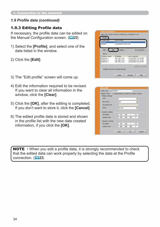
23)
the , and select one of the data listed in the window.
the [Edit].
window, click the [Clear].
the [OK], after the editing is completed. the [Cancel].
information, if you click the [OK].
connection. ( 23)
NOTE
1. Connection to the network
35
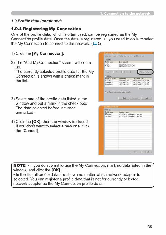
1.9.4 Registering My Connection
12)
[My Connection].
up.
the list.
window and put a mark in the check box.The data selected before is turned unmarked.
[OK], then the window is closed.
the [Cancel].
window, and click the [OK].NOTE
1. Connection to the network
36
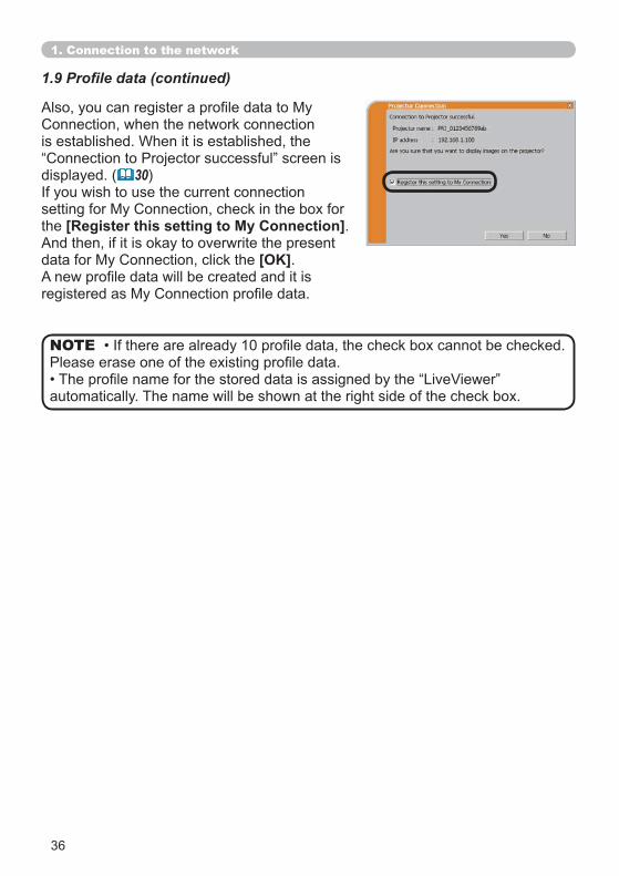
automatically. The name will be shown at the right side of the check box.
NOTE
displayed. ( 30)
the [Register this setting to My Connection].And then, if it is okay to overwrite the present
[OK].
1. Connection to the network
37
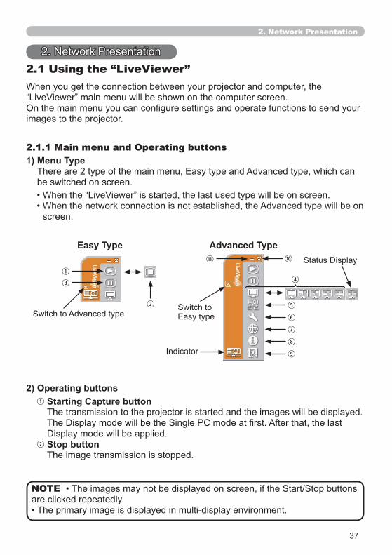
2.1 Using the “LiveViewer”
images to the projector.
1) Menu Type
be switched on screen.
2.1.1 Main menu and Operating buttons
screen.
Easy Type Advanced Type
2) Operating buttonsStarting Capture buttonThe transmission to the projector is started and the images will be displayed.
Stop buttonThe image transmission is stopped.
are clicked repeatedly.NOTE
2. Network Presentation
38
2. Network Presentation
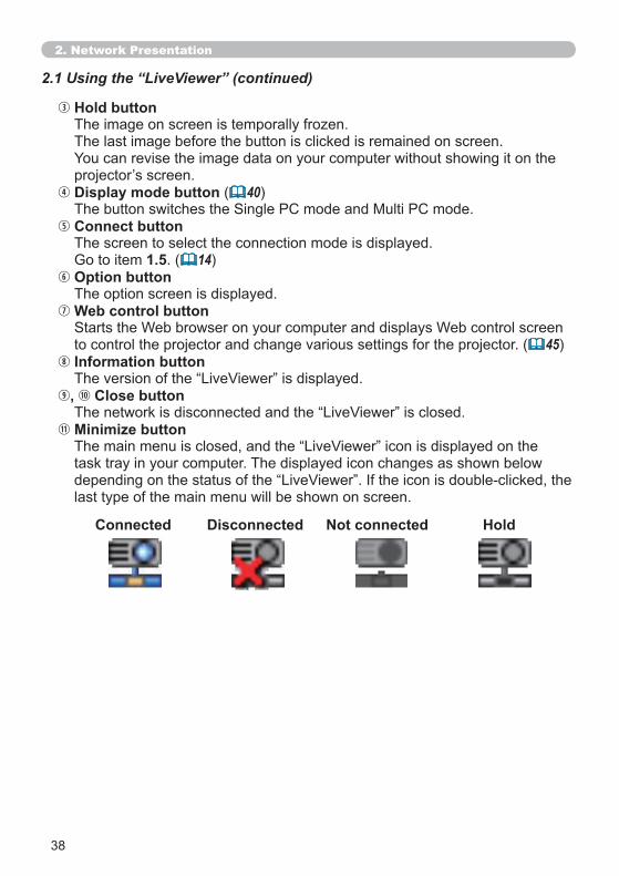
2.1 Using the “LiveViewer” (continued)
Hold button
The last image before the button is clicked is remained on screen.
Display mode button ( 40)
Connect buttonThe screen to select the connection mode is displayed.
1.5. ( 14)Option buttonThe option screen is displayed.Web control button
to control the projector and change various settings for the projector. ( 45)Information button
, Close button
Minimize button
task tray in your computer. The displayed icon changes as shown below
last type of the main menu will be shown on screen.
Connected Disconnected Not connected Hold
39
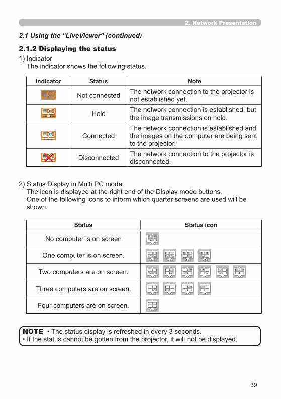
2.1.2 Displaying the status
The indicator shows the following status.
shown.
NOTE
Indicator Status Note
The network connection to the projector is not established yet.The network connection is established, but the image transmissions on hold.The network connection is established and the images on the computer are being sent to the projector.The network connection to the projector is disconnected.
Status Status icon
One computer is on screen.
Two computers are on screen.
Three computers are on screen.
Four computers are on screen.
2. Network Presentation
2.1 Using the “LiveViewer” (continued)
40
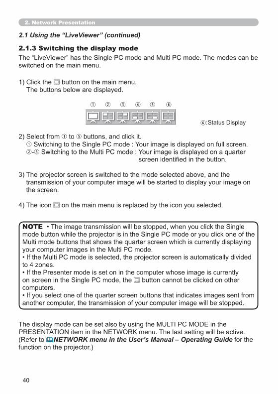
2.1.3 Switching the display mode
switched on the main menu.
button on the main menu.The buttons below are displayed.
to buttons, and click it.
3) The projector screen is switched to the mode selected above, and the transmission of your computer image will be started to display your image on the screen.
4) The icon on the main menu is replaced by the icon you selected.
(Refer to NETWORK menu in the User’s Manual – Operating Guide for the function on the projector.)
button cannot be clicked on other computers.
another computer, the transmission of your computer image will be stopped.
NOTE
2. Network Presentation
2.1 Using the “LiveViewer” (continued)
:
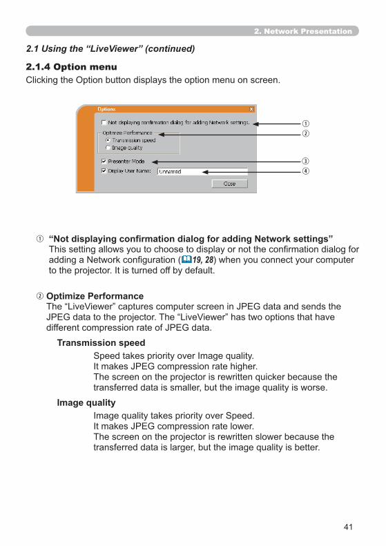
41
2.1.4 Option menu
Optimize Performance
19, 28) when you connect your computer
Transmission speed
Image quality
The screen on the projector is rewritten slower because the
2. Network Presentation
2.1 Using the “LiveViewer” (continued)
42
Presenter Mode
screen is unexpectedly switched to an image sent by another computer.
invalid.
mode setting of the computer is valid.
NOTE
Display User Name
characters.
whose image is currently on the screen.(Refer to NETWORK menu in the User’s Manual – Operating Guide)
2. Network Presentation
2.1 Using the “LiveViewer” (continued)
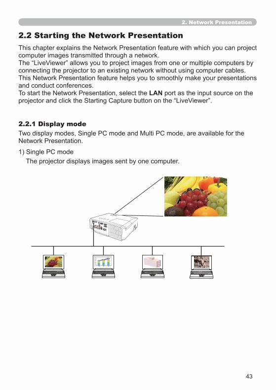
43
2. Network Presentation
2.2 Starting the Network Presentation
computer images transmitted through a network.
connecting the projector to an existing network without using computer cables.
and conduct conferences.LAN port as the input source on the
2.2.1 Display mode
The projector displays images sent by one computer.
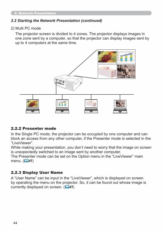
44
2. Network Presentation
2.2 Starting the Network Presentation (continued)
2.2.2 Presenter mode
2.2.3 Display User Name
is unexpectedly switched to an image sent by another computer.
menu. ( 41)
currently displayed on screen. ( 41)
up to 4 computers at the same time.
1 2
3 4

45
3. Web Control
computer that is connected to the same network.
NOTE
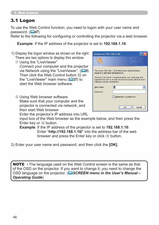
46
3. Web Control
3.1 Logon
password. ( 47)
1)There are two options to display this window.
9) on
37) to
projector is connected via network, and
button.Example 192.168.1.10:
http://192.168.1.10/ button.
[OK].
Example 192.168.1.10:
SCREEN menu in the User’s Manual – Operating Guide)
NOTE
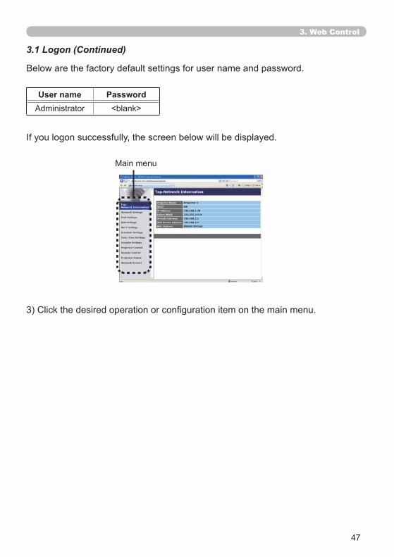
47
User name PasswordAdministrator <blank>
3.1 Logon (Continued)
3. Web Control
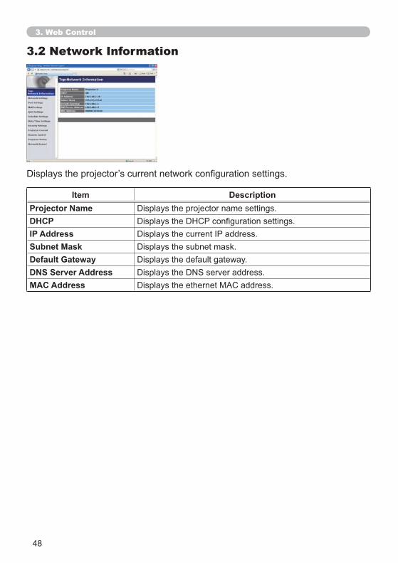
48
3.2 Network Information
Item DescriptionProjector NameDHCPIP AddressSubnet MaskDefault GatewayDNS Server AddressMAC Address
3. Web Control
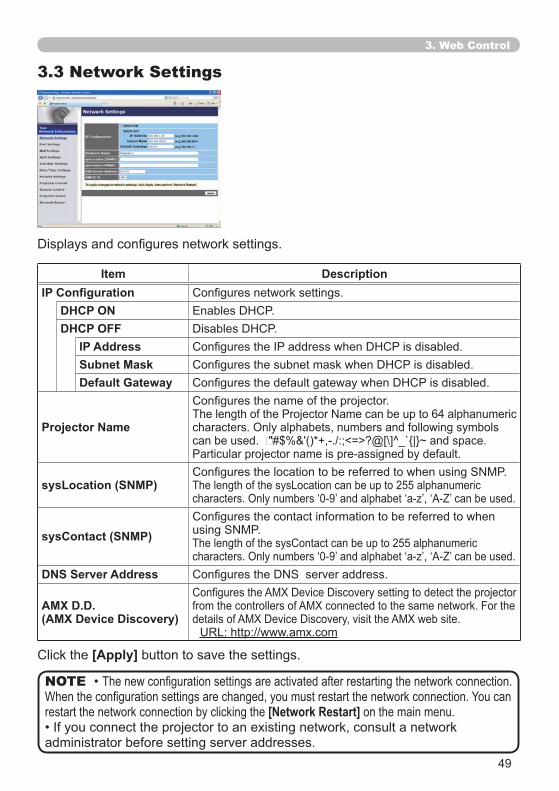
49
3.3 Network Settings
Item Description
DHCP ONDHCP OFF
IP AddressSubnet MaskDefault Gateway
Projector Name characters. Only alphabets, numbers and following symbols
sysLocation (SNMP)
sysContact (SNMP)
DNS Server Address
AMX D.D.(AMX Device Discovery)
restart the network connection by clicking the [Network Restart] on the main menu.
administrator before setting server addresses.
NOTE
3. Web Control
[Apply] button to save the settings.
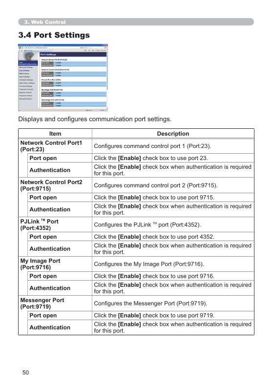
50
3.4 Port Settings
Item DescriptionNetwork Control Port1 (Port:23)
Port open [Enable] check box to use port 23.
Authentication [Enable]for this port.
Network Control Port2 (Port:9715)
Port open [Enable] check box to use port 9715.
Authentication [Enable]for this port.
PJLink TM Port (Port:4352)
Port open [Enable] check box to use port 4352.
Authentication [Enable]for this port.
My Image Port(Port:9716)
Port open [Enable] check box to use port 9716.
Authentication [Enable]for this port.
Messenger Port(Port:9719)
Port open [Enable] check box to use port 9719.
Authentication [Enable]for this port.
3. Web Control
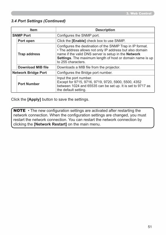
51
Item DescriptionSNMP Port
Port open [Enable]
Trap address NetworkSettings. The maximum length of host or domain name is up to 255 characters.
Network Bridge Port
Port Numberthe default setting.
[Apply] button to save the settings.
3.4 Port Settings (Continued)
clicking the [Network Restart] on the main menu.
NOTE
3. Web Control
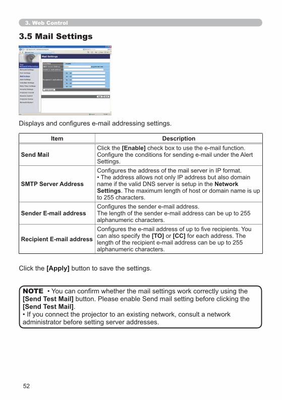
52
3.5 Mail Settings
Item Description
Send Mail[Enable]
SMTP Server Address NetworkSettings. The maximum length of host or domain name is up to 255 characters.
Sender E-mail addressalphanumeric characters.
Recipient E-mail address can also specify the [TO] or [CC] for each address. The
alphanumeric characters.
[Apply] button to save the settings.
[Send Test Mail][Send Test Mail].
administrator before setting server addresses.
NOTE
3. Web Control
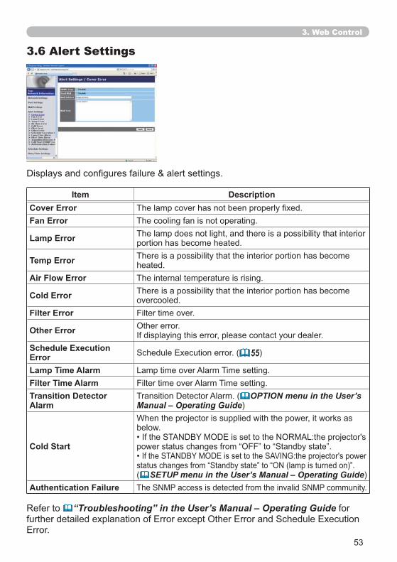
53
3.6 Alert Settings
Item DescriptionCover ErrorFan Error The cooling fan is not operating.
Lamp Error The lamp does not light, and there is a possibility that interior portion has become heated.
Temp Error There is a possibility that the interior portion has become heated.
Air Flow Error The internal temperature is rising.
Cold Error There is a possibility that the interior portion has become overcooled.
Filter Error Filter time over.
Other Error Other error.
Schedule Execution Error 55)
Lamp Time AlarmFilter Time Alarm Filter time over Alarm Time setting.Transition Detector Alarm
OPTION menu in the User’s Manual – Operating Guide)
Cold Start
below.
( SETUP menu in the User’s Manual – Operating Guide)Authentication Failure
Refer to “Troubleshooting” in the User’s Manual – Operating Guide for
3. Web Control
54
Item Description
Alarm Time (Only Lamp Time Alarm and Filter Time Alarm.)SNMP Trap [Enable]
Send Mail [Enable]Cold Start and Authentication Failure.)
Mail Subject The length of the subject line can be up to 100 alphanumeric characters.
Cold Start and Authentication Failure.)
Mail TextThe length of the text can be up to 1024 alphanumeric characters, but if you are using some of special characters below the length may be shorter.
and spaceCold Start and Authentication Failure.)
[Apply] button to save the settings.
Filter Error
OPTION menu in the User’s Manual – Operating Guide)
Lamp Time Alarm
Filter Time Alarm
NOTE
3.6 Alert Settings (Continued)
3. Web Control
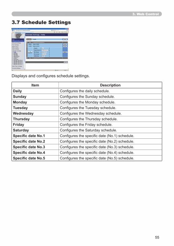
55
3.7 Schedule Settings
Item DescriptionDailySundayMondayTuesdayWednesdayThursdayFridaySaturday
3. Web Control
56
3.7 Schedule Settings (Continued)
The schedule settings are shown below.
Item DescriptionSchedule [Enable] check box to enable the schedule.
Date (Month/Day)selected.
[Apply] button to save the settings.
The current event settings are displayed on the schedule list. To add additional functions and events, set the following items.
Item DescriptionTimeCommand[Parameter]
PowerInput Source My Image 70)Messenger 72)Slideshow
[Register] button to add new commands to the schedule list.
[Delete] button to delete commands from the schedule list.
[Reset] button to delete all commands and reset the schedule settings from the schedule list.
3. Web Control
57
and time settings ( 58) get out of tune.My Image Messenger
display data are not stored in the projector at the scheduled event execution time.
Input Source My Imageis enabled and the projector is locked due to the feature.
display exists at the scheduled event time, a schedule execution error occurs
the USB TYPE A port.
Troubleshooting in the User's Manual – Operating Guide
NOTE
3.7 Schedule Settings (Continued)
3. Web Control
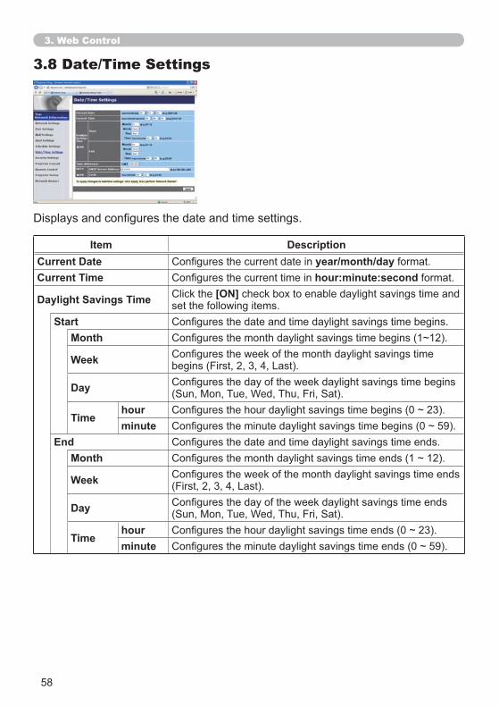
58
3.8 Date/Time Settings
Item DescriptionCurrent Date year/month/day format.Current Time hour:minute:second format.
Daylight Savings Time [ON] check box to enable daylight savings time and set the following items.
StartMonth
Week
Day
Timehourminute
EndMonth
Week
Day
Timehourminute
3. Web Control
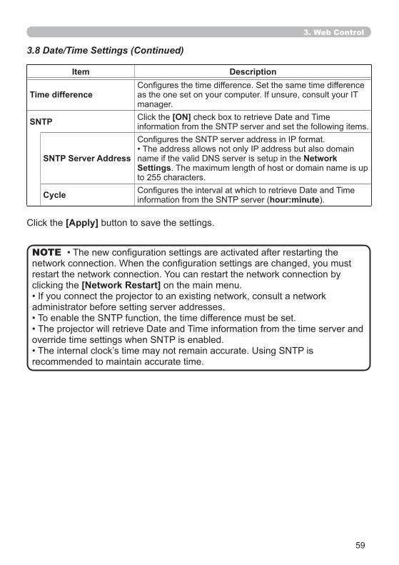
59
Item Description
Time differencemanager.
SNTP [ON]
SNTP Server Address NetworkSettings. The maximum length of host or domain name is up to 255 characters.
Cycle hour:minute).
[Apply] button to save the settings.
clicking the [Network Restart] on the main menu.
administrator before setting server addresses.
recommended to maintain accurate time.
NOTE
3.8 Date/Time Settings (Continued)
3. Web Control
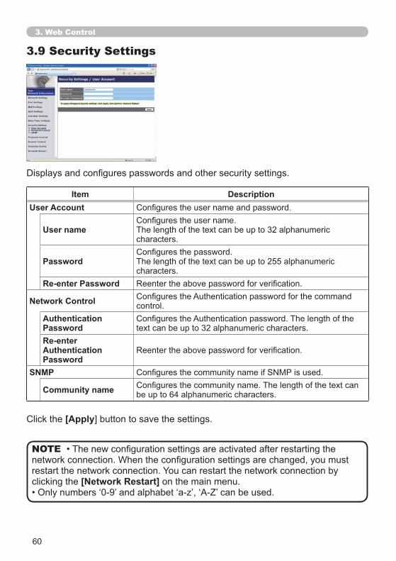
60
3.9 Security Settings
Item DescriptionUser Account
User name The length of the text can be up to 32 alphanumeric characters.
Password The length of the text can be up to 255 alphanumeric characters.
Re-enter Password
Network Control control.AuthenticationPassword text can be up to 32 alphanumeric characters.Re-enterAuthenticationPassword
SNMP
Community name be up to 64 alphanumeric characters.
[Apply
clicking the [Network Restart] on the main menu.
NOTE
3. Web Control
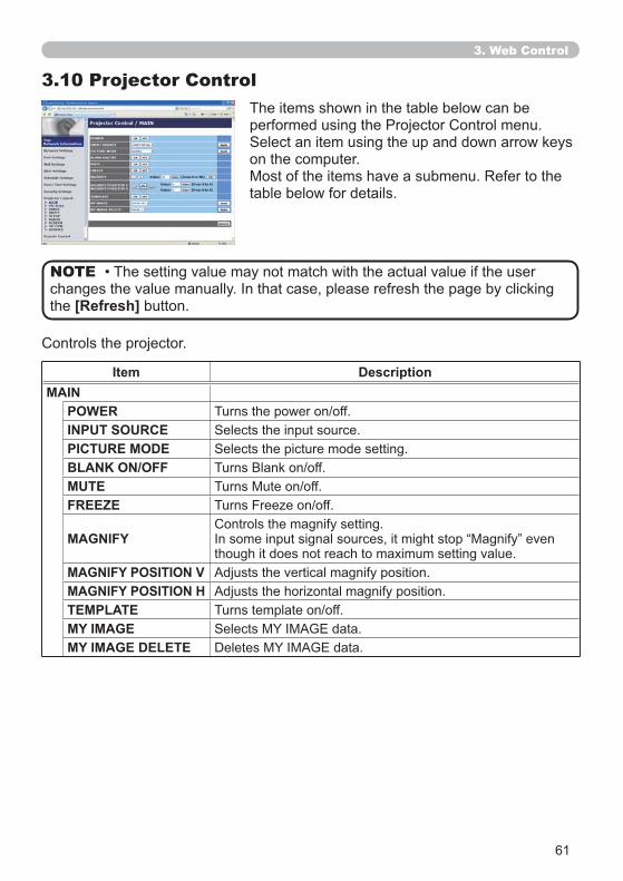
61
3.10 Projector Control
Item DescriptionMAIN
POWERINPUT SOURCEPICTURE MODEBLANK ON/OFFMUTEFREEZE
MAGNIFYthough it does not reach to maximum setting value.
MAGNIFY POSITION V Adjusts the vertical magnify position.MAGNIFY POSITION HTEMPLATEMY IMAGEMY IMAGE DELETE
The items shown in the table below can be
on the computer.
table below for details.
the [Refresh] button.
NOTE
3. Web Control
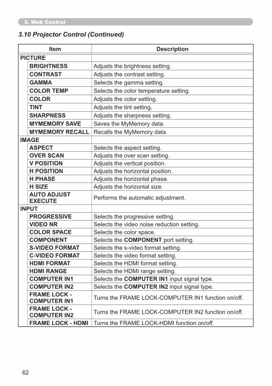
62
3.10 Projector Control (Continued)
Item DescriptionPICTURE
BRIGHTNESS Adjusts the brightness setting.CONTRAST Adjusts the contrast setting.GAMMACOLOR TEMPCOLOR Adjusts the color setting.TINT Adjusts the tint setting.SHARPNESS Adjusts the sharpness setting.MYMEMORY SAVEMYMEMORY RECALL
IMAGEASPECTOVER SCAN Adjusts the over scan setting.V POSITION Adjusts the vertical position.H POSITIONH PHASEH SIZEAUTO ADJUST EXECUTE
INPUTPROGRESSIVEVIDEO NRCOLOR SPACECOMPONENT COMPONENT port setting.S-VIDEO FORMATC-VIDEO FORMATHDMI FORMATHDMI RANGECOMPUTER IN1 COMPUTER IN1 input signal type.COMPUTER IN2 COMPUTER IN2 input signal type. FRAME LOCK - COMPUTER IN1FRAME LOCK - COMPUTER IN2FRAME LOCK - HDMI
3. Web Control
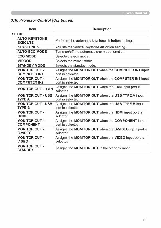
63
3.10 Projector Control (Continued)
Item DescriptionSETUP
AUTO KEYSTONE EXECUTEKEYSTONE V Adjusts the vertical keystone distortion setting.AUTO ECO MODEECO MODEMIRRORSTANDBY MODEMONITOR OUT - COMPUTER IN1
Assigns the MONITOR OUT when the COMPUTER IN1 input port is selected.
MONITOR OUT - COMPUTER IN2
Assigns the MONITOR OUT when the COMPUTER IN2 input port is selected.
MONITOR OUT - LAN Assigns the MONITOR OUT when the LAN input port is selected.
MONITOR OUT - USB TYPE A
Assigns the MONITOR OUT when the USB TYPE A input port is selected.
MONITOR OUT - USB TYPE B
Assigns the MONITOR OUT when the USB TYPE B input port is selected.
MONITOR OUT - HDMI
Assigns the MONITOR OUT when the HDMI input port is selected.
MONITOR OUT - COMPONENT
Assigns the MONITOR OUT when the COMPONENT input port is selected.
MONITOR OUT - S-VIDEO
Assigns the MONITOR OUT when the S-VIDEO input port is selected.
MONITOR OUT - VIDEO
Assigns the MONITOR OUT when the VIDEO input port is selected.
MONITOR OUT - STANDBY Assigns the MONITOR OUT in the standby mode.
3. Web Control
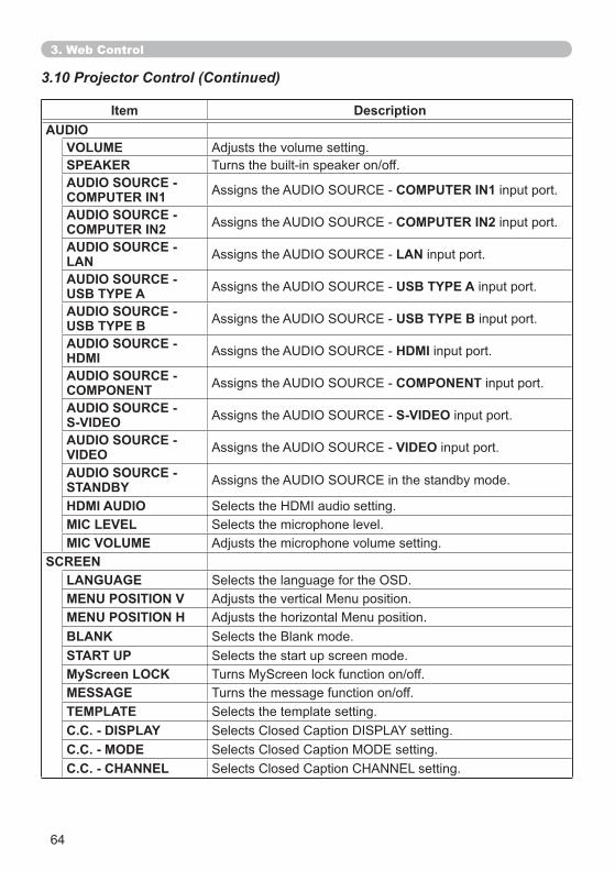
64
3.10 Projector Control (Continued)
3. Web Control
Item DescriptionAUDIO
VOLUME Adjusts the volume setting.SPEAKERAUDIO SOURCE - COMPUTER IN1 COMPUTER IN1 input port.
AUDIO SOURCE - COMPUTER IN2 COMPUTER IN2 input port.
AUDIO SOURCE - LAN LAN input port.
AUDIO SOURCE - USB TYPE A USB TYPE A input port.
AUDIO SOURCE - USB TYPE B USB TYPE B input port.
AUDIO SOURCE - HDMI HDMI input port.
AUDIO SOURCE - COMPONENT COMPONENT input port.
AUDIO SOURCE - S-VIDEO S-VIDEO input port.
AUDIO SOURCE - VIDEO VIDEO input port.
AUDIO SOURCE - STANDBYHDMI AUDIOMIC LEVELMIC VOLUME Adjusts the microphone volume setting.
SCREENLANGUAGEMENU POSITION VMENU POSITION HBLANKSTART UPMyScreen LOCKMESSAGETEMPLATEC.C. - DISPLAYC.C. - MODEC.C. - CHANNEL
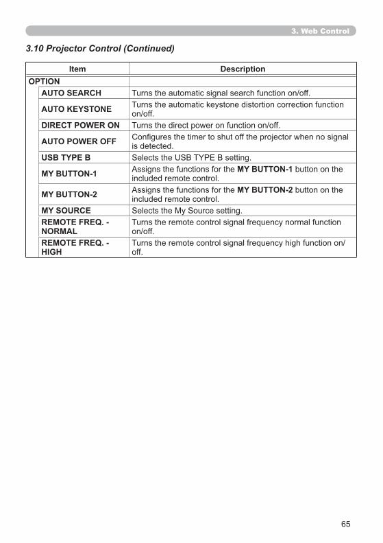
65
Item DescriptionOPTION
AUTO SEARCH
AUTO KEYSTONE Turns the automatic keystone distortion correction function
DIRECT POWER ON
AUTO POWER OFF is detected.USB TYPE B
MY BUTTON-1 Assigns the functions for the MY BUTTON-1 button on the included remote control.
MY BUTTON-2 Assigns the functions for the MY BUTTON-2 button on the included remote control.
MY SOURCEREMOTE FREQ. - NORMALREMOTE FREQ. - HIGH off.
3.10 Projector Control (Continued)
3. Web Control
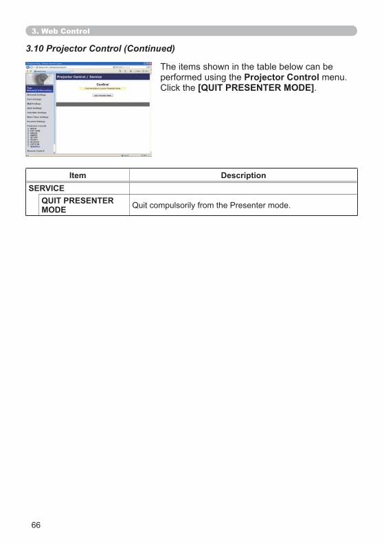
66
The items shown in the table below can be performed using the Projector Control menu.
[QUIT PRESENTER MODE].
Item DescriptionSERVICE
QUIT PRESENTER MODE
3.10 Projector Control (Continued)
3. Web Control
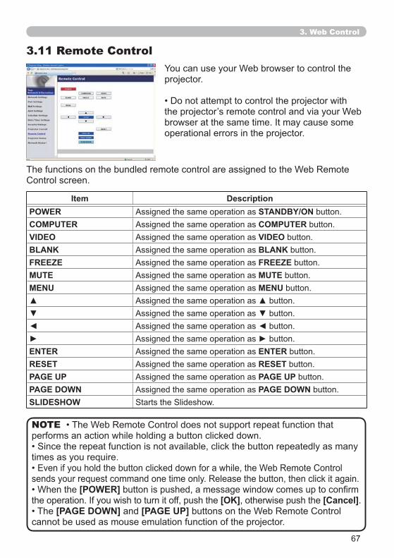
67
3.11 Remote Control
projector.
operational errors in the projector.
Item DescriptionPOWER Assigned the same operation as STANDBY/ON button.COMPUTER Assigned the same operation as COMPUTER button.VIDEO Assigned the same operation as VIDEO button.BLANK Assigned the same operation as BLANK button.FREEZE Assigned the same operation as FREEZE button.MUTE Assigned the same operation as MUTE button.MENU Assigned the same operation as MENU button.
ENTER Assigned the same operation as ENTER button.RESET Assigned the same operation as RESET button.PAGE UP Assigned the same operation as PAGE UP button.PAGE DOWN Assigned the same operation as PAGE DOWN button.SLIDESHOW
3. Web Control
performs an action while holding a button clicked down.
[POWER][OK], otherwise push the [Cancel].
[PAGE DOWN] and [PAGE UP]cannot be used as mouse emulation function of the projector.
NOTE
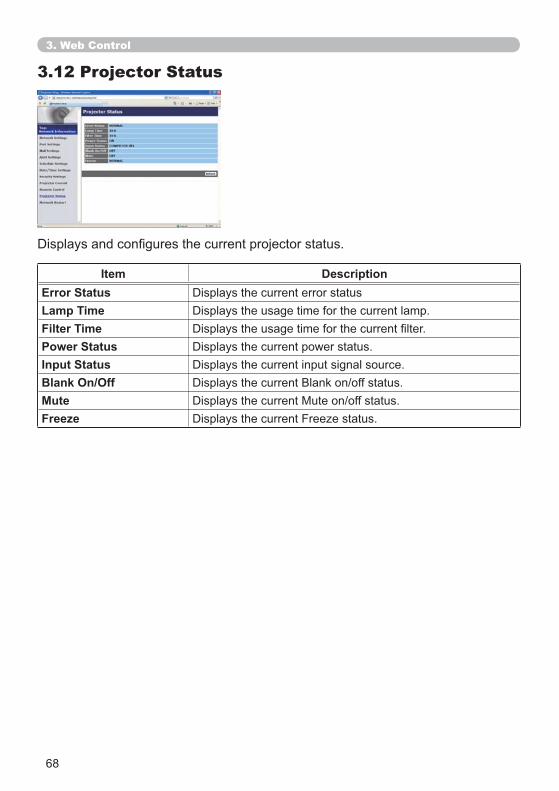
68
3.12 Projector Status
Item DescriptionError StatusLamp TimeFilter TimePower StatusInput StatusBlank On/OffMuteFreeze
3. Web Control
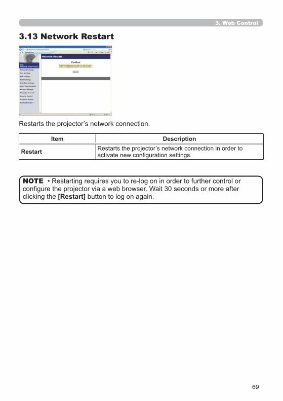
69
3.13 Network Restart
Item Description
Restart
clicking the [Restart] button to log on again.
NOTE
3. Web Control
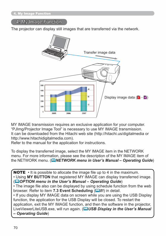
70
4. My Image Function
The projector can display still images that are transferred via the network.
MY BUTTON( OPTION menu in the User’s Manual – Operating Guide)
browser. Refer to item 7.3 Event Scheduling ( 81) in detail.
USB Display in the User’s Manual – Operating Guide)
NOTE
Transfer image data
1 4 )
Refer to the manual for the application for instructions.
NETWORK menu in User’s Manual – Operating Guide)
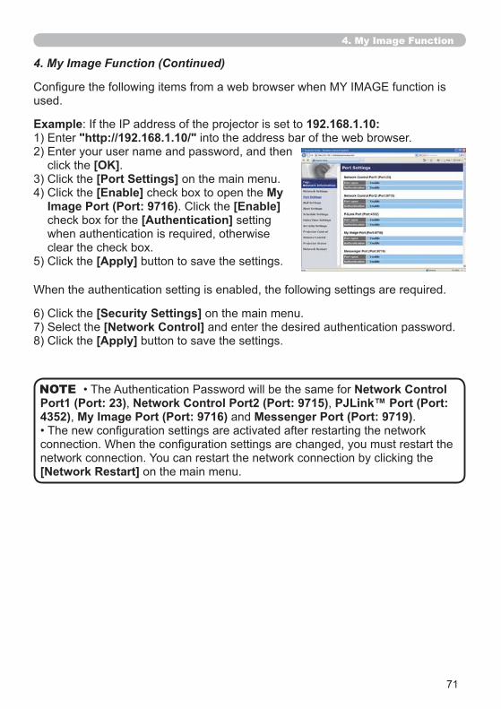
71
4. My Image Function
4. My Image Function (Continued)
used.
Example 192.168.1.10:"http://192.168.1.10/" into the address bar of the web browser.
click the [OK].[Port Settings] on the main menu.[Enable] check box to open the My
Image Port (Port: 9716) [Enable]check box for the [Authentication] setting
clear the check box.[Apply] button to save the settings.
[Security Settings] on the main menu.[Network Control] and enter the desired authentication password.
[Apply] button to save the settings.
Network Control Port1 (Port: 23), Network Control Port2 (Port: 9715), PJLink™ Port (Port: 4352), My Image Port (Port: 9716) and Messenger Port (Port: 9719).
[Network Restart] on the main menu.
NOTE
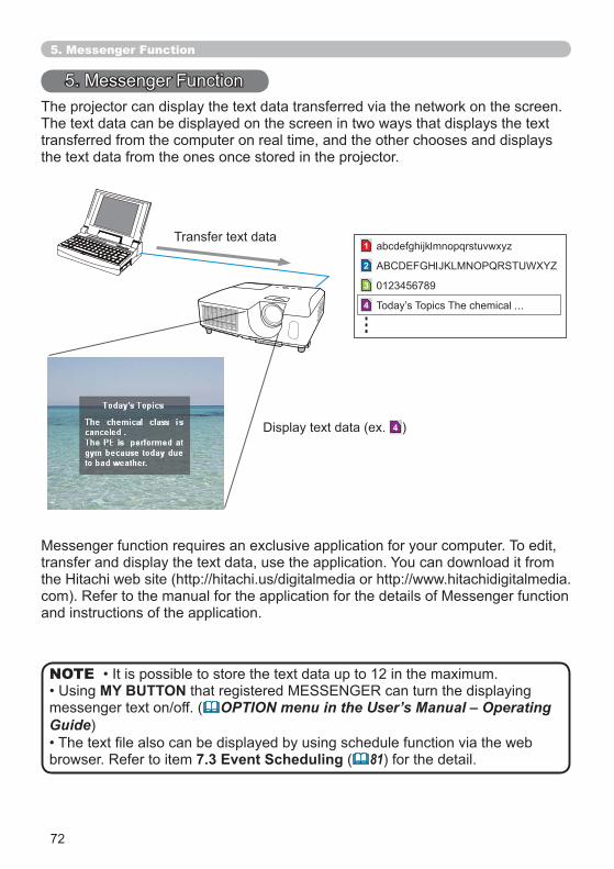
72
1
4
3
2
5. Messenger Function
The projector can display the text data transferred via the network on the screen. The text data can be displayed on the screen in two ways that displays the text transferred from the computer on real time, and the other chooses and displays the text data from the ones once stored in the projector.
MY BUTTON( OPTION menu in the User’s Manual – Operating
Guide)
browser. Refer to item 7.3 Event Scheduling ( 81) for the detail.
NOTE
Transfer text data
4 )
and instructions of the application.
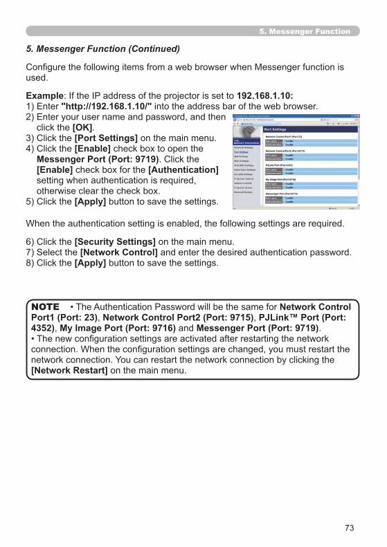
73
5. Messenger Function
5. Messenger Function (Continued)
used.
Example 192.168.1.10:"http://192.168.1.10/" into the address bar of the web browser.
click the [OK].[Port Settings] on the main menu.[Enable] check box to open the
Messenger Port (Port: 9719)[Enable] check box for the [Authentication]
otherwise clear the check box.[Apply] button to save the settings.
[Security Settings] on the main menu.[Network Control] and enter the desired authentication password.
[Apply] button to save the settings.
Network Control Port1 (Port: 23), Network Control Port2 (Port: 9715), PJLink™ Port (Port: 4352), My Image Port (Port: 9716) and Messenger Port (Port: 9719).
[Network Restart] on the main menu.
NOTE
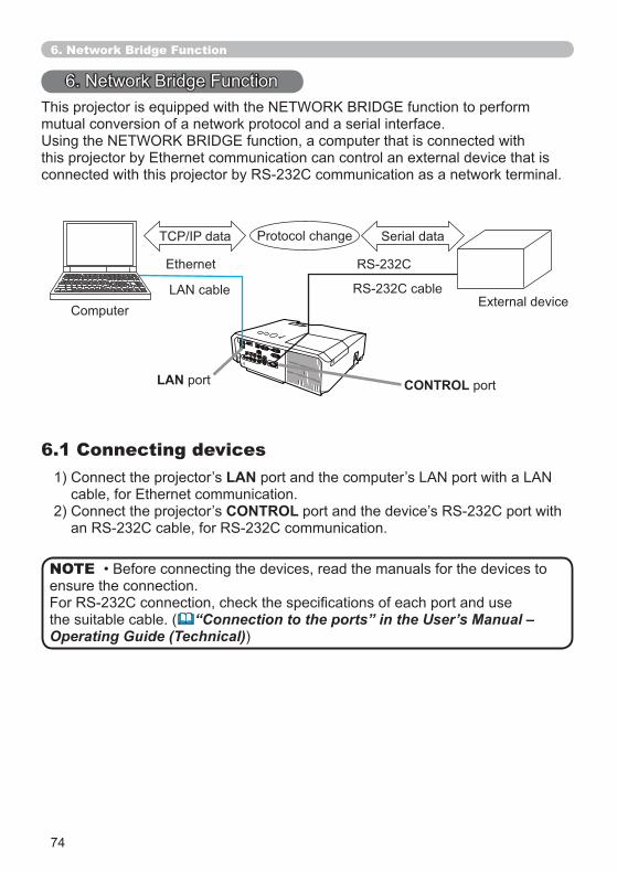
74
6. Network Bridge Function
mutual conversion of a network protocol and a serial interface.
6.1 Connecting devicesLAN
CONTROL
ensure the connection.
the suitable cable. ( “Connection to the ports” in the User’s Manual – Operating Guide (Technical))
NOTE
CONTROL portLAN port
75
6. Network Bridge Function
6.2 Communication setup
6.3 Communication port
for the CONTROL port.
for the CONTROLthe connected device.
projector with using the Network Bridge Port50)
CONTROL port according to your use.
setting.
that an unsuitable setup could cause malfunction of communication.CONTROL
and 65535 can be set up as the Network Bridge Portas the default setting.
NOTE
NOTE
Item Condition
( OPTION menu – SERVICE – COMMUNICATION in the User’s Manual – Operating Guide)
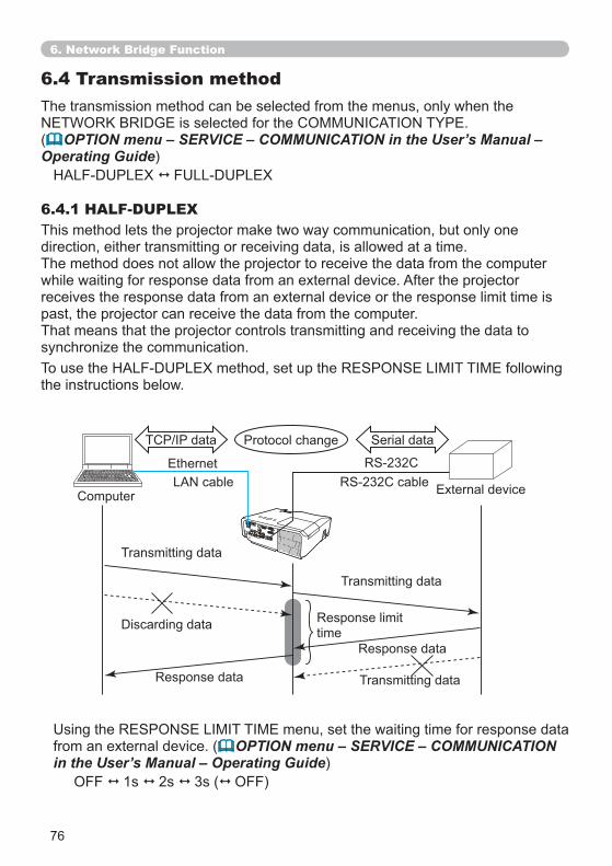
76
6.4 Transmission method
6.4.1 HALF-DUPLEX
The transmission method can be selected from the menus, only when the
( OPTION menu – SERVICE – COMMUNICATION in the User’s Manual – Operating Guide)
This method lets the projector make two way communication, but only one direction, either transmitting or receiving data, is allowed at a time.The method does not allow the projector to receive the data from the computer while waiting for response data from an external device. After the projector receives the response data from an external device or the response limit time is past, the projector can receive the data from the computer.That means that the projector controls transmitting and receiving the data to
the instructions below.
from an external device. ( OPTION menu – SERVICE – COMMUNICATION in the User’s Manual – Operating Guide)
OFF 1s 2s 3s ( OFF)
6. Network Bridge Function
Transmitting data
Transmitting data
Response limit time
Transmitting data
Response data
Response data
77
254 byte data as maximum at once.
from the computer and send it out to an external device continuously.The OFF is selected as the default setting.
and receiving the data, it may not be able to control an external device well depending on the processing status of the projector.
NOTE
NOTE
6.4.2 FULL-DUPLEXThis method lets the projector make two way communication, transmitting and receiving data at the same time, without monitoring response data from an external device.
6. Network Bridge Function
6.4 Transmission method (Continued)
78
7. Other Functions
7.1 E-mail Alerts
maintenance or detected an error.
power.
NOTE
Mail Settings ( 52)
through a web browser.
Example 192.168.1.10:“http://192.168.1.10/” into the address bar of the web browser.
[OK].[Mail Settings] 3.5 Mail
Settings ( 52) for further information. [Apply] button to save the settings.
[Send Test Mail] button in the [Mail Settings]NOTE
Time <Testing time>
7. Other Functions
79
7.1 E-mail Alerts (Continued)
7. Other Functions
[Alert Settings]settings.
3.6 Alert Setting ( 53) for further information.
[Apply] button to save the settings.
80
7.2 Projector Management using SNMP
projector information, which is a failure or warning status, from the computer on
to use this function.
administrator.
manager.
NOTE
NOTE
SNMP Settings ( 50)
Example 192.168.1.10:“http://192.168.1.10/” into the address bar of the web browser.
[OK].[Port Settings] on the main menu.
[Enable] check box to open the SNMP Port
[Security Settings] on the main menu. [SNMP] and set the community name on the screen that is displayed.
[Alert Settings]
[Enable][Enable][Apply] button to save the settings.
7. Other Functions
Community name has been [Network Restart]
NOTE
SNMP Port[Network Restart]
following items.
NOTE
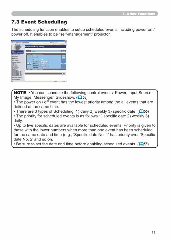
81
7.3 Event Scheduling
56)
55)
daily.
those with the lower numbers when more than one event has been scheduled
58)
NOTE
7. Other Functions
82
POWER
projector and the outlet. The schedule function does not work when the breaker in a room is tripped. The power indicator will lights orange or green when the
NOTE
Schedule Settings ( 55)7.3 Event Scheduling(Continued)
Example 192.168.1.10:“http://192.168.1.10/” into the address bar of the web browser.
[OK].[Schedule Settings]
schedule item. For example, if you want to perform the command every [Sunday].
[Enable] check box to enable scheduling.
[Apply] button to save the settings.[Register] to add
the new event.[Delete] button when you want to delete a schedule.
There are three types of scheduling.
7. Other Functions
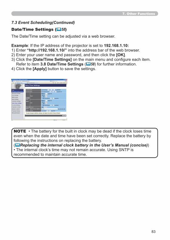
83
7.3 Event Scheduling(Continued)Date/Time Settings ( 58)
even when the date and time have been set correctly. Replace the battery by following the instructions on replacing the battery. ( Replacing the internal clock battery in the User’s Manual (concise))
recommended to maintain accurate time.
NOTE
Example 192.168.1.10:“http://192.168.1.10/” into the address bar of the web browser.
[OK].[Date/Time Settings]
Refer to item 3.8 Date/Time Settings ( 58) for further information.[Apply] button to save the settings.
7. Other Functions
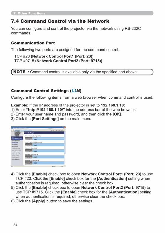
84
7.4 Command Control via the Network
commands.
Communication PortThe following two ports are assigned for the command control.
Command Control Settings ( 50)
[Enable] check box to open Network Control Port1 (Port: 23) to use [Enable] check box for the [Authentication] setting when
[Enable] check box to open Network Control Port2 (Port: 9715) to [Enable] check box for the [Authentication] setting
[Apply] button to save the settings.
Example 192.168.1.10: “http://192.168.1.10/” into the address bar of the web browser.
[OK].[Port Settings] on the main menu.
7. Other Functions
(Network Control Port1 (Port: 23))(Network Control Port2 (Port: 9715))
NOTE
85
7.4 Command Control via the Network (Continued)
( 60)
[Security Settings] on the main menu. [Network Control] and enter the desired authentication password.
[Apply] button to save the settings.
NOTE
7. Other Functions
Network Control Port1 (Port: 23), Network Control Port2 (Port: 9715), PJLink™ Port (Port: 4352), My Image Port (Port: 9716) and Messenger Port (Port: 9719).
[Network Restart] on the main menu.
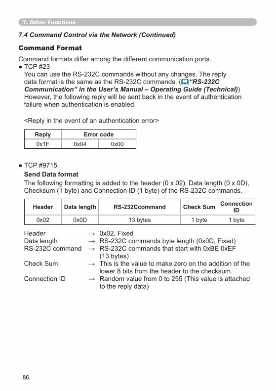
86
Command Format
“RS-232CCommunication” in the User’s Manual – Operating Guide (Technical))
failure when authentication is enabled.
Header Data length RS-232Ccommand Check Sum ConnectionID
0x02 13 bytes 1 byte 1 byte
Reply Error code0x1F 0x04 0x00
<Reply in the event of an authentication error>
(13 bytes)
lower 8 bits from the header to the checksum.
to the reply data)
Send Data format
7. Other Functions
7.4 Command Control via the Network (Continued)
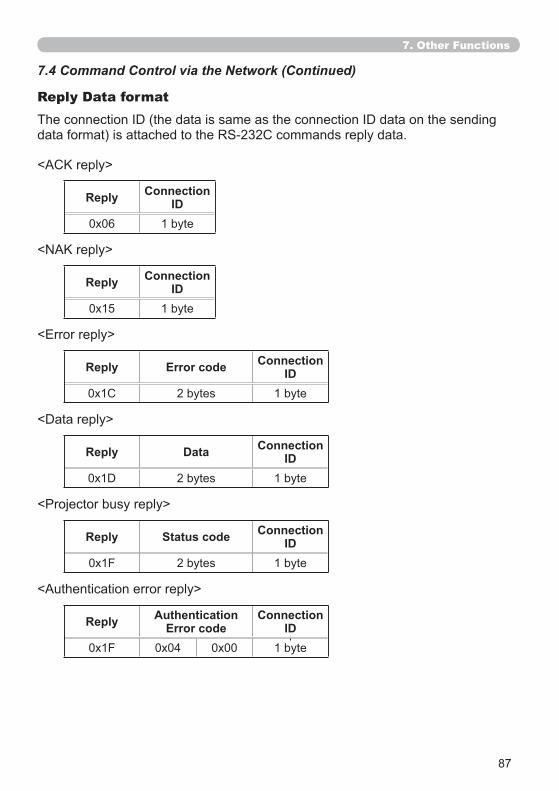
87
Reply Data format
Reply ConnectionID
0x06 1 byte
Reply ConnectionID
0x15 1 byte
Reply Error code ConnectionID
2 bytes 1 byte
<Authentication error reply>
Reply Data ConnectionID
2 bytes 1 byte
Reply Status code ConnectionID
0x1F 2 bytes 1 byte
Reply AuthenticationError code
ConnectionID
0x1F 0x04 0x00 1 byte
7. Other Functions
7.4 Command Control via the Network (Continued)
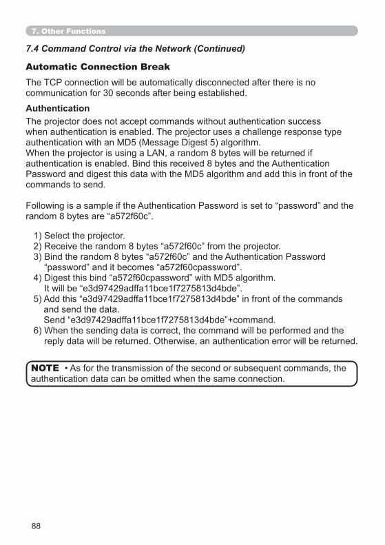
88
Automatic Connection Break
communication for 30 seconds after being established.
The projector does not accept commands without authentication success when authentication is enabled. The projector uses a challenge response type
commands to send.
Authentication
and send the data.
reply data will be returned. Otherwise, an authentication error will be returned.
authentication data can be omitted when the same connection.NOTE
7. Other Functions
7.4 Command Control via the Network (Continued)
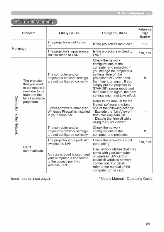
89
8. Troubleshooting
8. Troubleshooting
Problem Likely Cause Things to CheckReference
PageNumber
The projector is not turned on. *17
*18, *19
The projector that you want to connect to is nowhere to be found on the list of available projectors
are not configured correctly.
configurations of the
settings, turn off the
simply put the projector in
then turn it on again, the new settings might not take effect.
8
Firewall software other than
in your computer.
Refer to the manual for the
one of the following actions:
from blocking item list–
communicate
configurations of the computer and projector.
8
port setting. *18, *19
An access point is used, and your computer is connected to the access point via
come with your computer
establish wireless network connection. For detail, refer to the manual of the computer or the card.
–
(continued on next page)
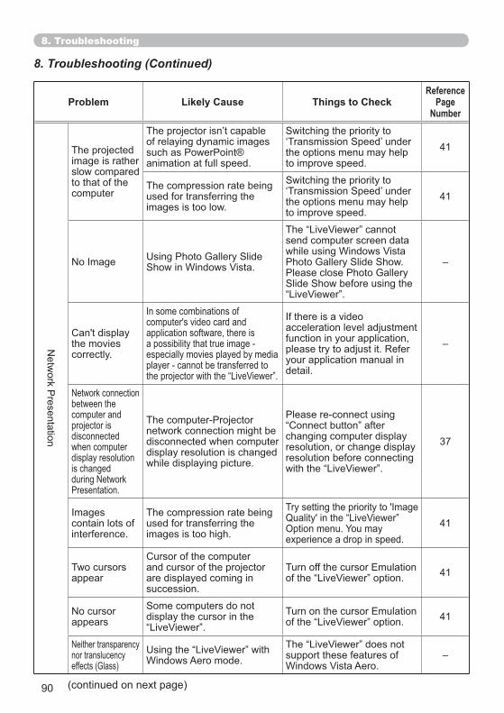
90
Problem Likely Cause Things to CheckReference
PageNumber
The projected image is rather slow compared to that of the computer
of relaying dynamic images
animation at full speed.the options menu may help to improve speed.
41
The compression rate being used for transferring the images is too low. the options menu may help
to improve speed.41
send computer screen data
–
the movies correctly.
application software, there is
especially movies played by media
acceleration level adjustment function in your application, please try to adjust it. Refer your application manual in detail.
–
between the computer and projector is disconnectedwhen computerdisplay resolution is changed
network connection might be disconnected when computer display resolution is changed while displaying picture.
changing computer display resolution, or change display resolution before connecting
37
contain lots of interference.
The compression rate being used for transferring the images is too high. experience a drop in speed.
41
Two cursors appear
and cursor of the projector are displayed coming in succession.
41
appears display the cursor in the 41
nor translucency support these features of –
8. Troubleshooting
8. Troubleshooting (Continued)
(continued on next page)
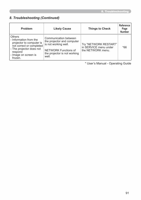
91
Problem Likely Cause Things to CheckReference
PageNumber
Others
projector to computer is not correct or completed
respond
the projector and computer is not working well.
the projector is not working well.
*66
8. Troubleshooting (Continued)
8. Troubleshooting

92
9. Warranty and after-sales service
8. Troubleshooting ( 89)
dealer or service company, if you still have the problem. They will tell you what warranty condition is applied.
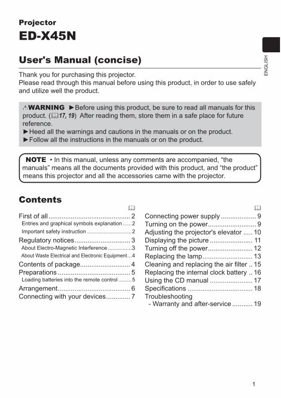
1
EN
GLI
SH
Projector
ED-X45N
User's Manual (concise)Thank you for purchasing this projector.Please read through this manual before using this product, in order to use safely and utilize well the product.
WARNINGproduct. ( 17, 19) After reading them, store them in a safe place for future reference.
............................................ 2 Entries and graphical symbols explanation ......2 Important safety instruction ..............................2
Regulatory notices.............................. 3 About Electro-Magnetic Interference ................3 About Waste Electrical and Electronic Equipment...4
Contents of package........................... 4Preparations ....................................... 5 Loading batteries into the remote control .........5
Arrangement....................................... 6Connecting with your devices............. 7
Connecting power supply ................... 9Turning on the power.......................... 9Adjusting the projector's elevator ..... 10Displaying the picture ....................... 11Turning off the power........................ 12Replacing the lamp........................... 13
.. 15Replacing the internal clock battery .. 16Using the CD manual ....................... 17
................................... 18Troubleshooting - Warranty and after-service ........... 19
Contents
NOTE
means this projector and all the accessories came with the projector.

2
First of allEntries and graphical symbols explanationThe following entries and graphical symbols are used for the manuals and the product as follows, for safety purpose. Please know their meanings beforehand, and heed them.
Important safety instruction
follow them always when handling the product. The manufacturer assumes no responsibility for any damage caused by mishandling that is beyond normal usage
WARNING This entry warns of a risk of serious personal injury or even death.CAUTION This entry warns of a risk of personal injury or physical damage.
NOTICE This entry notices of fear of causing trouble.
WARNING Never use the product in or after an abnormality (ex. giving off smoke, smelling strange, took a liquid or an object inside, broken, etc.) If an abnormality should occur, unplug the projector urgently.
Situate the product away from children and pets.Do not use the product when there is fear of a thunderbolt.Unplug the projector from the power outlet if the projector is not used for the
time being.Do not open or remove any portion of the product, unless the manuals direct
Do not modify the projector or accessories.Do not let any things or any liquids enter to the inside of the product.Do not wet the product.Do not apply a shock or pressure to this product.
- Do not place the product on an unstable place such as the uneven surface or the leaned table.
- Do not place the product unstably. Place the projector so that it does not protrude from the surface where the projector is placed on.
- Remove all the attachments including the power cord and cables, from the projector when carrying the projector.Do not look into the lens and the openings on the projector, while the lamp is
on.Do not approach the lamp cover and the exhaust vents, while the projection
lamp is on. Also after the lamp goes out, do not approach them for a while, since too hot.
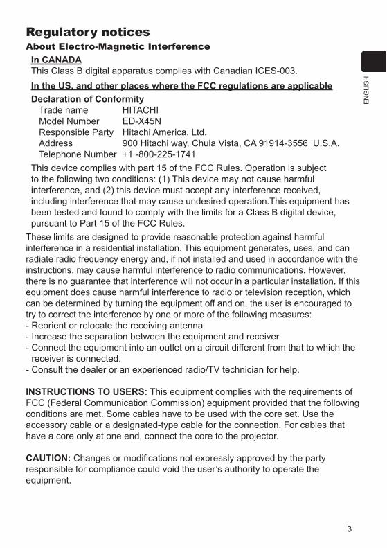
3
EN
GLI
SH
Regulatory noticesAbout Electro-Magnetic Interference
In CANADA
In the US, and other places where the FCC regulations are applicableDeclaration of Conformity
Trade name HITACHIModel Number ED-X45NResponsible Party Hitachi America, Ltd.Address 900 Hitachi way, Chula Vista, CA 91914-3556 U.S.A.Telephone Number +1 -800-225-1741
to the following two conditions: (1) This device may not cause harmful interference, and (2) this device must accept any interference received, including interference that may cause undesired operation.This equipment has
These limits are designed to provide reasonable protection against harmful interference in a residential installation. This equipment generates, uses, and can radiate radio frequency energy and, if not installed and used in accordance with the instructions, may cause harmful interference to radio communications. However, there is no guarantee that interference will not occur in a particular installation. If this equipment does cause harmful interference to radio or television reception, which can be determined by turning the equipment off and on, the user is encouraged to try to correct the interference by one or more of the following measures:- Reorient or relocate the receiving antenna.- Increase the separation between the equipment and receiver.- Connect the equipment into an outlet on a circuit different from that to which the
receiver is connected.- Consult the dealer or an experienced radio/TV technician for help.
INSTRUCTIONS TO USERS: This equipment complies with the requirements of
conditions are met. Some cables have to be used with the core set. Use the
have a core only at one end, connect the core to the projector.
CAUTION:responsible for compliance could void the user’s authority to operate the equipment.

4
Contents of packageYour projector should come with the items shown below. Check that all the items are included. Require of your dealer immediately if any items are missing.(1) Remote control with two AA batteries (2) Power cord (3) Computer cable(4) Lens cover
(6) Security label(7) Application CD
NOTEto use the original packing materials when moving the projector. Use special caution for the lens.
(5)
(6)
(2)
(3)
(4)(1) VIDEO DOC.CAMERA
KEYSTONE
ASPECT SEARCH BLANK
MUTEMY BUTTON
POSITION
1 2
ESC
ENTER
MENU
RESET
COMPUTERMY SOURCE/
AUTO
MAGNIFY PAGE UP
VOLUME
DOWN
ON
OFF
FREEZE
About Waste Electrical and Electronic EquipmentThe mark is in compliance with the Waste Electrical and Electronic Equipment Directive 2002/96/EC (WEEE).
including any spent or discarded batteries or accumulators as unsorted municipal waste, but use the return and collection systems available.If the batteries or accumulators included with this equipment, display the chemical symbol Hg, Cd, or Pb, then it means that the battery has a heavy metal content of more than 0.0005% Mercury or more than, 0.002% Cadmium, or more than 0.004% Lead.
Regulatory notices (continued)
(7)
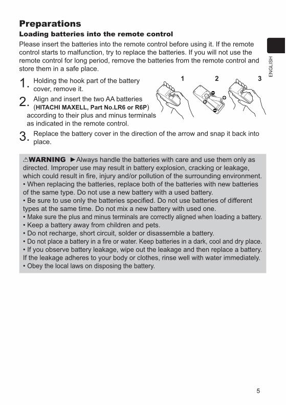
5
EN
GLI
SH
PreparationsLoading batteries into the remote controlPlease insert the batteries into the remote control before using it. If the remote control starts to malfunction, try to replace the batteries. If you will not use the remote control for long period, remove the batteries from the remote control and store them in a safe place.
1. Holding the hook part of the battery cover, remove it.
2. Align and insert the two AA batteries (HITACHI MAXELL, Part No.LR6 or R6P)
according to their plus and minus terminals as indicated in the remote control.
3. Replace the battery cover in the direction of the arrow and snap it back into place.
WARNING Always handle the batteries with care and use them only as directed. Improper use may result in battery explosion, cracking or leakage,
When replacing the batteries, replace both of the batteries with new batteries of the same type. Do not use a new battery with a used battery.
types at the same time. Do not mix a new battery with used one. Make sure the plus and minus terminals are correctly aligned when loading a battery.
If you observe battery leakage, wipe out the leakage and then replace a battery. If the leakage adheres to your body or clothes, rinse well with water immediately.
21 3
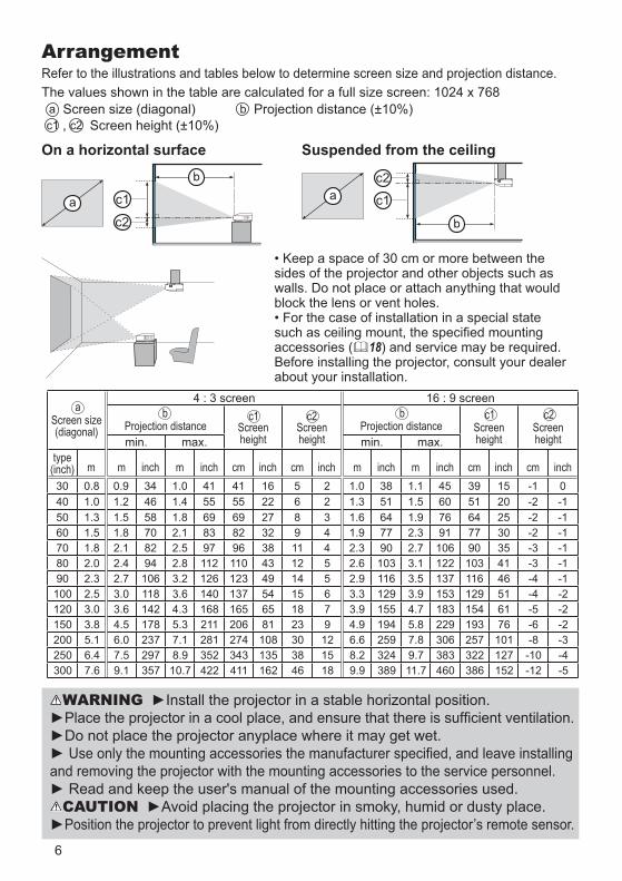
6
On a horizontal surface Suspended from the ceiling
sides of the projector and other objects such as walls. Do not place or attach anything that would block the lens or vent holes.
accessories ( 18) and service may be required.
about your installation.
WARNING
and removing the projector with the mounting accessories to the service personnel.
CAUTIONPosition the projector to prevent light from directly hitting the projector’s remote sensor.
Screen size(diagonal)
4 : 3 screen 16 : 9 screen
Projection distance Screenheight
Screenheight
Projection distance Screenheight
Screenheightmin. max. min. max.
type(inch) m m inch m inch cm inch cm inch m inch m inch cm inch cm inch30 0.8 0.9 34 1.0 41 41 16 5 2 1.0 38 1.1 45 39 15 -1 040 1.0 1.2 46 1.4 55 55 22 6 2 1.3 51 1.5 60 51 20 -2 -150 1.3 1.5 58 1.8 69 69 27 8 3 1.6 64 1.9 76 64 25 -2 -160 1.5 1.8 70 2.1 83 82 32 9 4 1.9 77 2.3 91 77 30 -2 -170 1.8 2.1 82 2.5 97 96 38 11 4 2.3 90 2.7 106 90 35 -3 -180 2.0 2.4 94 2.8 112 110 43 12 5 2.6 103 3.1 122 103 41 -3 -190 2.3 2.7 106 3.2 126 123 49 14 5 2.9 116 3.5 137 116 46 -4 -1100 2.5 3.0 118 3.6 140 137 54 15 6 3.3 129 3.9 153 129 51 -4 -2120 3.0 3.6 142 4.3 168 165 65 18 7 3.9 155 4.7 183 154 61 -5 -2150 3.8 4.5 178 5.3 211 206 81 23 9 4.9 194 5.8 229 193 76 -6 -2200 5.1 6.0 237 7.1 281 274 108 30 12 6.6 259 7.8 306 257 101 -8 -3250 6.4 7.5 297 8.9 352 343 135 38 15 8.2 324 9.7 383 322 127 -10 -4300 7.6 9.1 357 10.7 422 411 162 46 18 9.9 389 11.7 460 386 152 -12 -5
ba b c1c1 c2 c2
ArrangementRefer to the illustrations and tables below to determine screen size and projection distance.The values shown in the table are calculated for a full size screen: 1024 x 768
a Screen size (diagonal) b Projection distance (±10%)c1 , c2 Screen height (±10%)
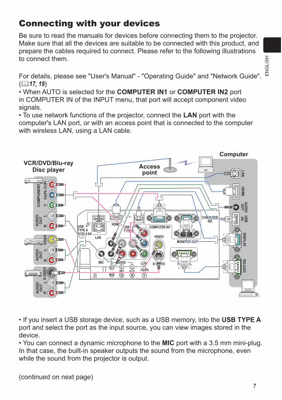
7
EN
GLI
SH
RL
CO
MPO
NEN
T
Cb/P
bY
Cr/P
r
AU
DIO
OU
T
MIC
HDMIUSBTYPE B
USBTYPE ADC5V 0.5A
LAN
COMPUTER IN1
COMPUTERIN2
VIDEO
S-VIDEO CONTROL
MONITOR OUT
AUDIO
OUTIN3IN1
IN2
L
R
L
R YCb/Pb
Cr/Pr
HD
MI
RL
RL
VIDE
OS-
VIDE
O
AU
DIO
OU
TA
UD
IOO
UT
AUDIOO
UTUSB(A)
DISPLAYRS-232C
LAN
Connecting with your devices
Make sure that all the devices are suitable to be connected with this product, and prepare the cables required to connect. Please refer to the following illustrations to connect them.
( 17, 19)COMPUTER IN1 or COMPUTER IN2 port
signals.LAN port with the
computer's LAN port, or with an access point that is connected to the computer with wireless LAN, using a LAN cable.
Accesspoint
ComputerVCR/DVD/Blu-ray
Disc player
(continued on next page)
USB TYPE Aport and select the port as the input source, you can view images stored in the device.
MIC port with a 3.5 mm mini-plug. In that case, the built-in speaker outputs the sound from the microphone, even while the sound from the projector is output.
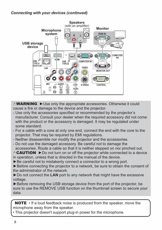
8
MIC
HDMIUSBTYPE B
USBTYPE ADC5V 0.5A
LAN
COMPUTER IN1
COMPUTERIN2
VIDEO
S-VIDEO CONTROL
MONITOR OUT
AUDIO
OUTIN3IN1
IN2
L
R
L
R YCb/Pb
Cr/Pr
R LRGB IN
Connecting with your devices (continued)
Monitor
NOTEmicrophone away from the speaker.
WARNING
manufacturer. Consult your dealer when the required accessory did not come with the product or the accessory is damaged. It may be regulated under some standard.
projector. That may be required by EMI regulations.- Neither disassemble nor modify the projector and the accessories.
accessories. Route a cable so that it is neither stepped on nor pinched out.CAUTION
in operation, unless that is directed in the manual of the device.
the administrator of the network.LAN port to any network that might have the excessive
voltage.
data.
USB storage device
Microphonesystem
Speakers
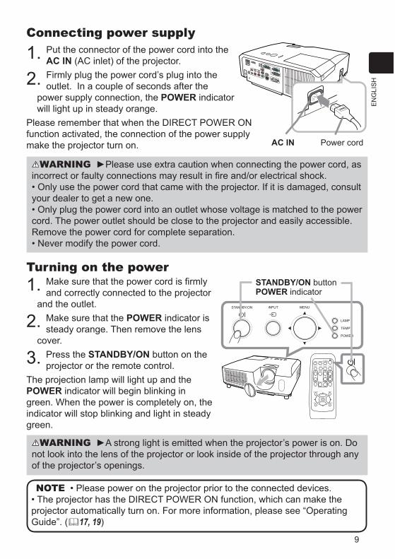
9
EN
GLI
SH
Connecting power supply
1. Put the connector of the power cord into the AC IN (AC inlet) of the projector.
2. outlet. In a couple of seconds after the power supply connection, the POWER indicator will light up in steady orange.
function activated, the connection of the power supply make the projector turn on.
Turning on the power1. and correctly connected to the projector
and the outlet.
2. Make sure that the POWER indicator is steady orange. Then remove the lens
cover.
3. Press the STANDBY/ON button on the projector or the remote control.
The projection lamp will light up and the POWER indicator will begin blinking in green. When the power is completely on, the indicator will stop blinking and light in steady green.
VIDEO DOC.CAMERA
KEYSTONE
ASPECT SEARCH BLANK
MUTEMY BUTTON
POSITION
1 2
ESC
ENTER
MENU
RESET
COMPUTERMY SOURCE/
AUTO
MAGNIFY PAGE UP
VOLUME
DOWN
ON
OFF
FREEZE
WARNING Please use extra caution when connecting the power cord, as
your dealer to get a new one.
cord. The power outlet should be close to the projector and easily accessible. Remove the power cord for complete separation.
WARNINGnot look into the lens of the projector or look inside of the projector through any of the projector’s openings.
NOTE
Guide”. ( 17, 19)
AC IN Power cord
STANDBY/ON buttonPOWER indicator
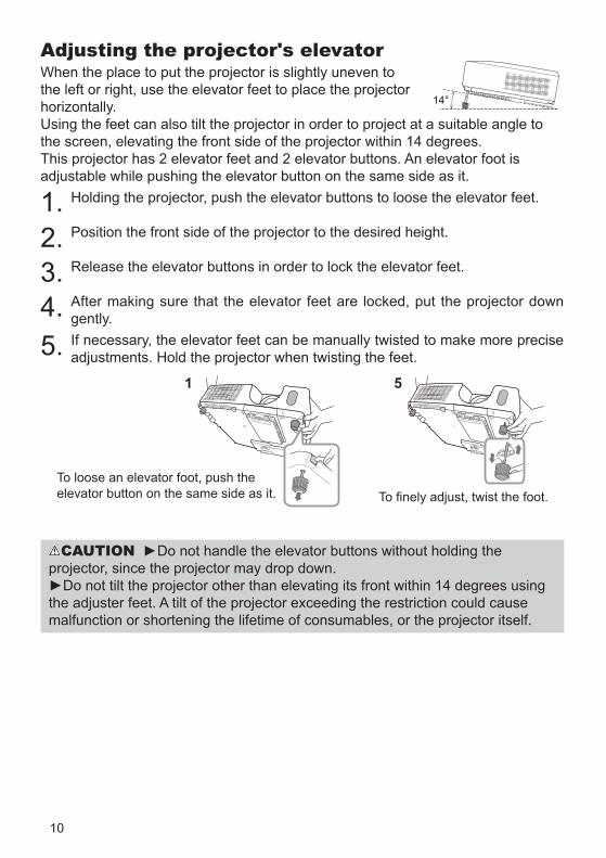
10
Adjusting the projector's elevatorWhen the place to put the projector is slightly uneven to the left or right, use the elevator feet to place the projector horizontally. Using the feet can also tilt the projector in order to project at a suitable angle to the screen, elevating the front side of the projector within 14 degrees.This projector has 2 elevator feet and 2 elevator buttons. An elevator foot is adjustable while pushing the elevator button on the same side as it.
1. Holding the projector, push the elevator buttons to loose the elevator feet.
2. Position the front side of the projector to the desired height.
3. Release the elevator buttons in order to lock the elevator feet.
4. After making sure that the elevator feet are locked, put the projector down gently.
5. If necessary, the elevator feet can be manually twisted to make more precise adjustments. Hold the projector when twisting the feet.
To loose an elevator foot, push the elevator button on the same side as it.
CAUTIONprojector, since the projector may drop down.
the adjuster feet. A tilt of the projector exceeding the restriction could cause malfunction or shortening the lifetime of consumables, or the projector itself.
14°
51
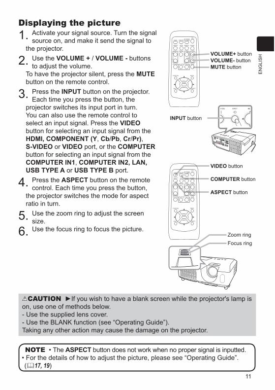
11
EN
GLI
SH
Displaying the picture1. Activate your signal source. Turn the signal
source on, and make it send the signal to the projector.
2. Use the VOLUME + / VOLUME - buttons to adjust the volume.
To have the projector silent, press the MUTEbutton on the remote control.
3. Press the INPUT button on the projector. Each time you press the button, the
projector switches its input port in turn.You can also use the remote control to select an input signal. Press the VIDEObutton for selecting an input signal from the HDMI, COMPONENT (Y, Cb/Pb, Cr/Pr),S-VIDEO or VIDEO port, or the COMPUTERbutton for selecting an input signal from the COMPUTER IN1, COMPUTER IN2, LAN,USB TYPE A or USB TYPE B port.
4. Press the ASPECT button on the remote control. Each time you press the button,
the projector switches the mode for aspect ratio in turn.
5. Use the zoom ring to adjust the screen size.
6. Use the focus ring to focus the picture.
INPUT button
VOLUME+ buttonVOLUME- buttonMUTE button
VIDEO button
COMPUTER button
ASPECT button
NOTE The ASPECT button does not work when no proper signal is inputted.
( 17, 19)
VIDEO DOC.CAMERA
KEYSTONE
ASPECT SEARCH BLANK
MUTEMY BUTTON
POSITION
1 2
ESC
ENTER
MENU
RESET
COMPUTERMY SOURCE/
AUTO
MAGNIFY PAGE UP
VOLUME
DOWN
ON
OFF
FREEZE
VIDEO DOC.CAMERA
KEYSTONE
ASPECT SEARCH BLANK
MUTEMY BUTTON
POSITION
1 2
ESC
ENTER
MENU
RESET
COMPUTERMY SOURCE/
AUTO
MAGNIFY PAGE UP
VOLUME
DOWN
ON
OFF
FREEZE
Zoom ring
CAUTIONon, use one of methods below.- Use the supplied lens cover.
Taking any other action may cause the damage on the projector.
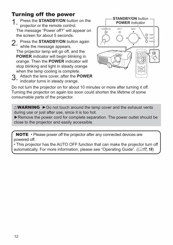
12
Turning off the power1. Press the STANDBY/ON button on the
projector or the remote control.
the screen for about 5 seconds.
2. Press the STANDBY/ON button again while the message appears.
The projector lamp will go off, and the POWER indicator will begin blinking in orange. Then the POWER indicator will stop blinking and light in steady orange when the lamp cooling is complete.
3. Attach the lens cover, after the POWERindicator turns in steady orange.
Do not turn the projector on for about 10 minutes or more after turning it off. Turning the projector on again too soon could shorten the lifetime of some consumable parts of the projector.
VIDEO DOC.CAMERA
KEYSTONE
ASPECT SEARCH BLANK
MUTEMY BUTTON
POSITION
1 2
ESC
ENTER
MENU
RESET
COMPUTERMY SOURCE/
AUTO
MAGNIFY PAGE UP
VOLUME
DOWN
ON
OFF
FREEZE
WARNINGduring use or just after use, since it is too hot.
close to the projector and easily accessible.
NOTE Please power off the projector after any connected devices are powered off.
( 17, 19)
STANDBY/ON buttonPOWER indicator
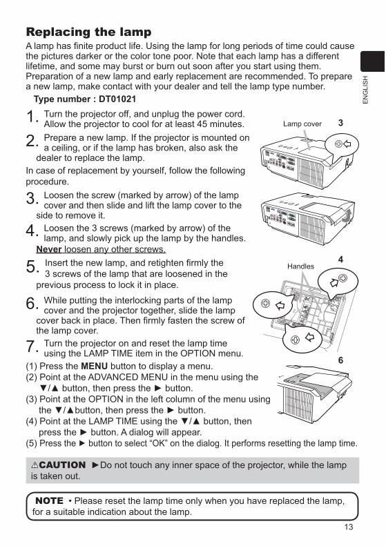
13
EN
GLI
SH
Replacing the lamp
the pictures darker or the color tone poor. Note that each lamp has a different lifetime, and some may burst or burn out soon after you start using them.Preparation of a new lamp and early replacement are recommended. To prepare a new lamp, make contact with your dealer and tell the lamp type number.
Type number : DT01021
1. Turn the projector off, and unplug the power cord. Allow the projector to cool for at least 45 minutes.
2. Prepare a new lamp. If the projector is mounted on a ceiling, or if the lamp has broken, also ask the
dealer to replace the lamp.In case of replacement by yourself, follow the following procedure.
3. Loosen the screw (marked by arrow) of the lamp cover and then slide and lift the lamp cover to the
side to remove it.
4. Loosen the 3 screws (marked by arrow) of the lamp, and slowly pick up the lamp by the handles.
Never loosen any other screws.
5. 3 screws of the lamp that are loosened in the previous process to lock it in place.
6. While putting the interlocking parts of the lamp cover and the projector together, slide the lamp
the lamp cover.
7. Turn the projector on and reset the lamp time
(1) Press the MENU button to display a menu. (2) Point at the ADVANCED MENU in the menu using the
(5) Press the button to select ” on the dialog. It performs resetting the lamp time.
NOTEfor a suitable indication about the lamp.
CAUTIONis taken out.
Lamp cover
4
3
6
Handles

14
HIGH VOLTAGE HIGH TEMPERATURE HIGH PRESSUREWARNING The projector uses a high-pressure mercury glass lamp. The
lamp can break with a loud bang, or burn out, if jolted or scratched, handled while hot, or worn over time. Note that each lamp has a different lifetime, and some may burst or burn out soon after you start using them. In addition, if the
from the projector’s vent holes.About disposal of a lamp: This product contains a mercury lamp; do not put
it in a trash. Dispose of it in accordance with environmental laws. www.lamprecycle.org (in the US).
or www.eiae.org (in the US) or www.epsc.ca (in Canada).
unplug the power cord from the outlet, and make sure to request a replacement lamp from your local dealer. Note that shards of glass could damage the projector’s internals, or cause injury during handling, so please do not try to clean the projector or replace the lamp yourself.
ventilate the room well, and make sure not to inhale the gas or fine particles that come out from the projector's vent holes, and not to get them into your eyes or mouth.
cord, then wait at least 45 minutes for the lamp to cool sufficiently. Handling the lamp while hot can cause burns, as well as damaging the lamp.
a ceiling. This is dangerous, since if the lamp’s bulb has broken, the shards will fall out when the cover is opened. In addition, working in high places is dangerous, so ask your local dealer to have the lamp replaced even if the bulb is not broken.
replacing, make sure that the screws are screwed in firmly. Loose screws could result in damage or injury.
Use only the lamp of the specified type. Use of a lamp that does not
shorten the life of this product.
that there are electrical problems elsewhere besides the lamp. If this happens, consult your local dealer or a service representative.
Handle with care: jolting or scratching could cause the lamp bulb to burst during use.
up or to burst. When the pictures appear dark, or when the color tone is poor, please replace the lamp as soon as possible. Do not use old (used) lamps; this is a cause of breakage.
Disconnectthe plug from the poweroutlet
Replacing the lamp (continued)

15
EN
GLI
SH
Type number : MU06481
lamp for this projector.
1. Turn the projector off, and unplug the power cord. Allow the
2.3. While supporting the projector with one hand, use your
the arrow.
4.5.6.
replace them with the new ones.
7.side up.
8.9. .
(1) Press the MENU button to display a menu.
” on the dialog. It
WARNING
.
NOTE
turn off the projector, to prevent the internal heat level rising.
2
4
3
7
Stitchedside

16
1. Turn the projector off, and unplug the power cord. Allow the projector to cool
2. After making sure that the projector has cooled adequately, slowly turn over the projector, so that the bottom is facing.
3. Turn the battery cover fully in the direction
and pick the cover up to remove it.
4. screwdriver or the like to take it out. While
battery since it may pop out of the holder.
5. Replace the battery with a new HITACHI MAXELL, Part No. CR2032 or CR2032H.Slide the battery in under the plastic claw, and push it into the holder until it clicks.
6. Replace the battery cover in place, then
WARNING
environment pollution.
such as a scratch, a dent, rust or leakage.
When a battery leaked, wipe the leakage out well with a waste cloth. If the leakage adhered to your body, immediately rinse it well with water. When a battery leaked in the battery holder, replace the batteries after wiping the leakage out.
battery.
or water.
a battery. If swallowed consult a physician immediately for emergency treatment.
Replacing the internal clock battery This projector has internal clock that uses a battery. When the clock of the network function does not work correctly, please try solution by replacement of the battery:
HITACHI MAXELL, part number CR2032 or CR2032H.
NOTE( 17, 19)
OPEN
CLOS
E
OPEN
CLOS
E
OPENCLOSE
90°
OPEN
CLOS
E90°
17
EN
GLI
SH
Using the CD manual
to ensure the proper use.
System requirements
Windows®: ® Windows® 98, Windows® 98SE, Windows NT®4.0, Windows® Me, Windows® 2000/Windows® XP or laterCPU:Pentium®
Macintosh®: ® 10.2 or laterCPU:PowerPC®
CD-ROM drive: Display: 256 color / 640x480 dots resolution Applications: Microsoft® Internet Explorer®4.0 and
Adobe® Acrobat® Reader® 4.0 or laterHow to use the CD
Windows®: In a while, Web browser automatically starts. Start up window comes up.
Macintosh®:desktop screen.
and Initial window will appear.2. Click the model name of your projector first, and then click language you want
from the displayed list. The User’s manual (detailed) will open.
CAUTION
CD drive may produce a loud noise, which in turn MAY RESULT IN EAR AND
the CD neither in direct sunlight nor in a high temperature and high humidity environment.
NOTE
projector. ( 19)
reproduced or republished without notice to our company.
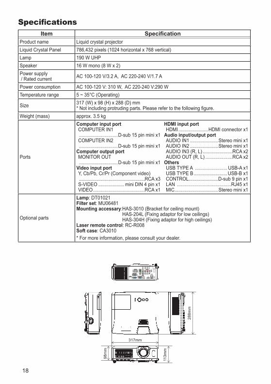
18
ItemProduct name Liquid crystal projectorLiquid Crystal Panel 786,432 pixels (1024 horizontal x 768 vertical)Lamp 190 W UHPSpeaker 16 W mono (8 W x 2)Power supply / Rated current AC 100-120 V/3.2 A, AC 220-240 V/1.7 A
Power consumption AC 100-120 V: 310 W, AC 220-240 V:290 WTemperature range
Size 317 (W) x 98 (H) x 288 (D) mm
Weight (mass) approx. 3.5 kg
Ports
Computer input port
..............................D-sub 15 pin mini x1
..............................D-sub 15 pin mini x1Computer output port
..............................D-sub 15 pin mini x1Video input portY, Cb/Pb, Cr/Pr (Component video) ...................................................RCA x3
.................... mini DIN 4 pin x1........................................RCA x1
HDMI input portHDMI.......................HDMI connector x1
Audio input/output port......................Stereo mini x1......................Stereo mini x1
.......................RCA x2.....................RCA x2
Others.........................
.................................................D-sub 9 pin x1
LAN ..........................................RJ45 x1 MIC..................................Stereo mini x1
Lamp: DT01021 Filter set: MU06481Mounting accessary
Laser remote control: RC-R008Soft case: CA3010
317mm
113m
m
98m
m
288m
m
LAN
MIC
HDMIUSB
IN1
IN2
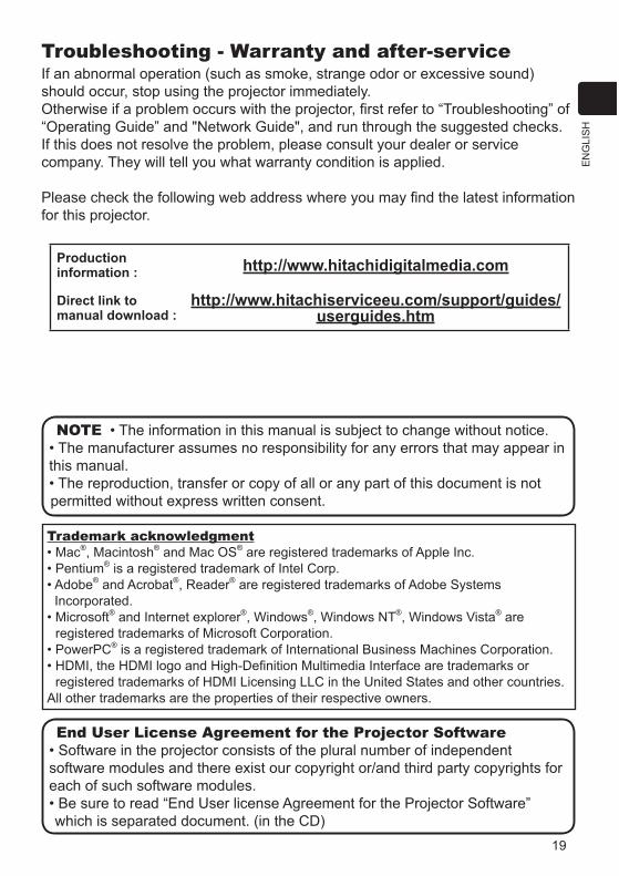
19
EN
GLI
SH
Troubleshooting - Warranty and after-serviceIf an abnormal operation (such as smoke, strange odor or excessive sound) should occur, stop using the projector immediately.
If this does not resolve the problem, please consult your dealer or service company. They will tell you what warranty condition is applied.
for this projector.
Productioninformation : http://www.hitachidigitalmedia.com
Direct link to manual download :
http://www.hitachiserviceeu.com/support/guides/userguides.htm
Trademark acknowledgment®, Macintosh® ® are registered trademarks of Apple Inc.
® is a registered trademark of Intel Corp.® and Acrobat®, Reader® are registered trademarks of Adobe Systems
Incorporated.® and Internet explorer®, Windows®, Windows NT®, Windows Vista® are
registered trademarks of Microsoft Corporation.®
registered trademarks of HDMI Licensing LLC in the United States and other countries.All other trademarks are the properties of their respective owners.
NOTE
this manual.
permitted without express written consent.
End User License Agreement for the Projector Software
software modules and there exist our copyright or/and third party copyrights for each of such software modules.
which is separated document. (in the CD)
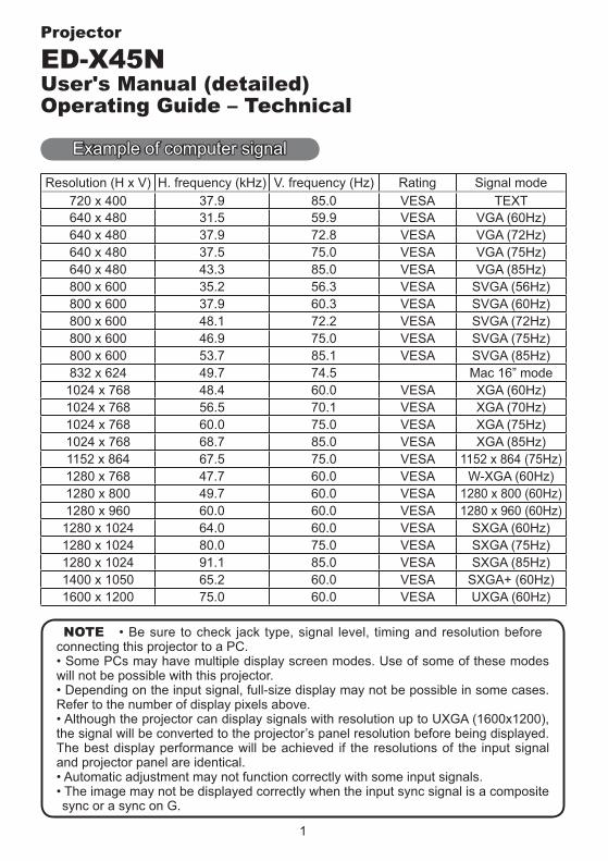
1
NOTE
Projector
ED-X45NUser's Manual (detailed)Operating Guide – Technical
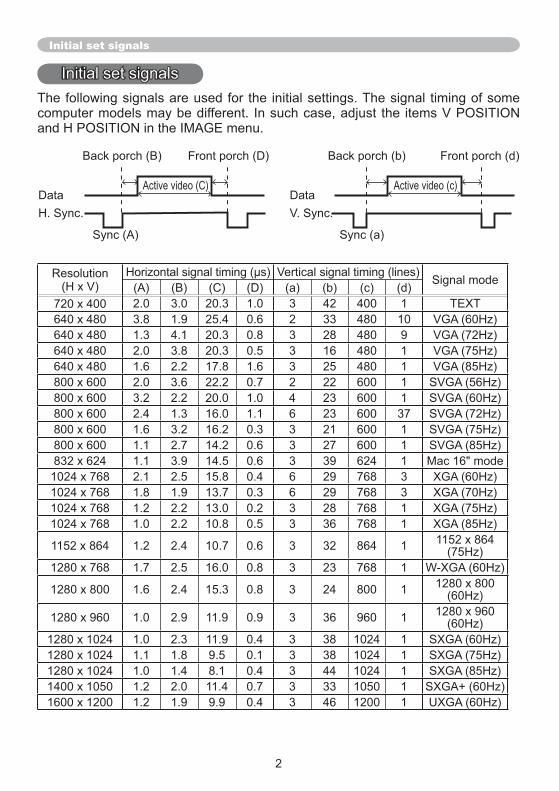
Initial set signals
Back porch (B) Front porch (D) Back porch (b) Front porch (d)
Active video (C)Data DataH. Sync. V. Sync.
Sync (A) Sync (a)
Active video (c)
3 133
33 13 1
1137
3 13 13 1
33
3 13 1
3 1
3 1
3 1
3 1
3 38 13 38 13 13 33 13 1
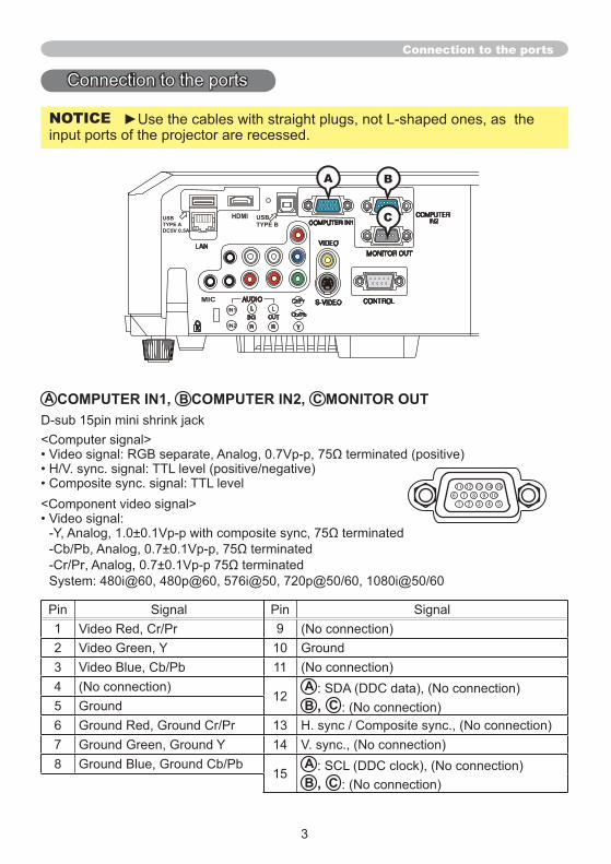
3
LAN
MIC
HDMI
IN1
IN2
USBTYPE B
USBTYPE ADC5V 0.5A
A COMPUTER IN1, B COMPUTER IN2, C MONITOR OUT
1
3 11A
5 B , C13
78
15AB , C
Connection to the ports
BA
C
NOTICE
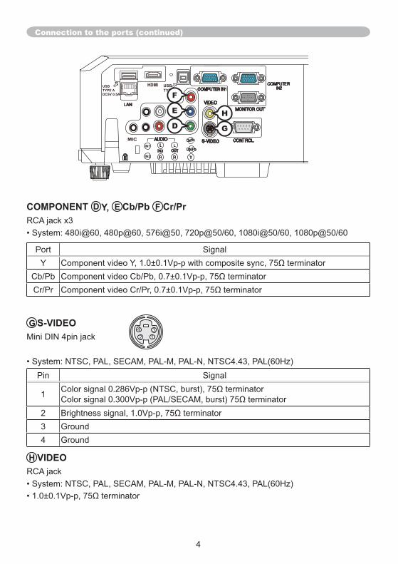
LAN
MIC
HDMI
IN1
IN2
USBTYPE B
USBTYPE ADC5V 0.5A
G S-VIDEO
1
3
Connection to the ports (continued)
31
H VIDEO
COMPONENT D Y, E Cb/Pb F Cr/Pr
Y
GDH
F
E
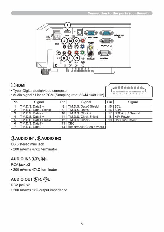
5
LAN
MIC
HDMI
IN1
IN2
USBTYPE B
USBTYPE ADC5V 0.5A
Connection to the ports (continued)
J AUDIO IN1, K AUDIO IN2
AUDIO IN3 L R, M L
AUDIO OUT N R, O L
I
L NK
I HDMI
1 8 15
3 1711 18
513
7
17 15 13 11 7 5 3 1
18 8
J M O
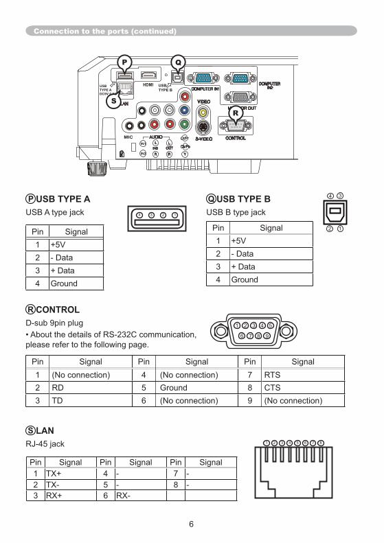
LAN
MIC
HDMI
IN1
IN2
USBTYPE B
USBTYPE ADC5V 0.5A
Connection to the ports (continued)
Q USB TYPE B
1
3
3
1
R CONTROL
1 75 8
3
P
R
S LAN87531
1 75 8
3
531
7 8
P USB TYPE A3 1
1
3
Q
S
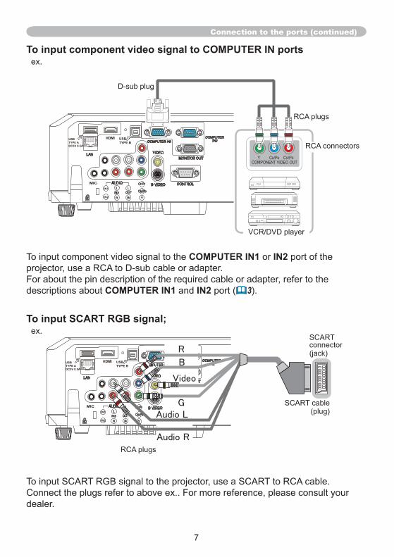
7
To input SCART RGB signal;
LAN
MIC
HDMI
IN1
IN2
USBTYPE B
USBTYPE ADC5V 0.5A
Connection to the ports (continued)
To input component video signal to COMPUTER IN ports
COMPUTER IN1 IN2
COMPUTER IN1 IN2 3
LAN
MIC
HDMI
IN1
IN2
USBTYPE B
USBTYPE ADC5V 0.5A
Y CB/PB CR/PRCOMPONENT VIDEO OUT
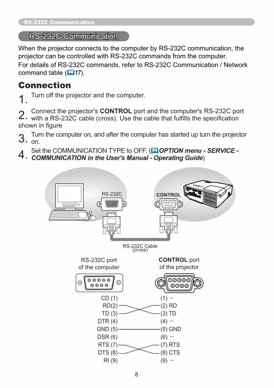
8
-
-
-
-
RS-232C Communication
17
Connection
CONTROL
OPTION menu - SERVICE - COMMUNICATION in the User's Manual - Operating Guide
1 2 43
8 9
5
76
CONTROL
CONTROLRS-232C
RS-232C Cable (cross)
531
7 8
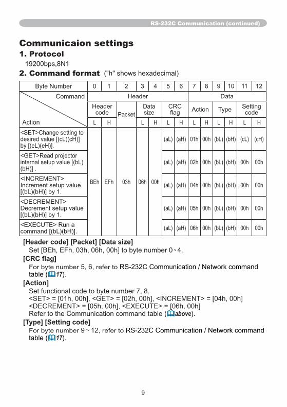
RS-232C Communication (continued)
Communicaion settings1. Protocol
2. Command format1 3 5 7 8 11
[Header code] [Packet] [Data size] ~
17[Action]
< <
above[Type] [Setting code]
~17

RS-232C Communication (continued)
3. Response code / Error code(1) ACK reply : 06h
(2) NAK reply : 15h
(3) Error reply : 1Ch + 0000h
(4) Data reply : 1Dh + xxxxh
NOTE
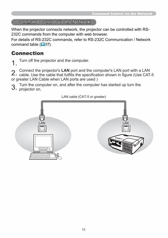
11
17
Connection
LAN
Command Control via the Network
LANLAN
LAN cable (CAT-5 or greater)
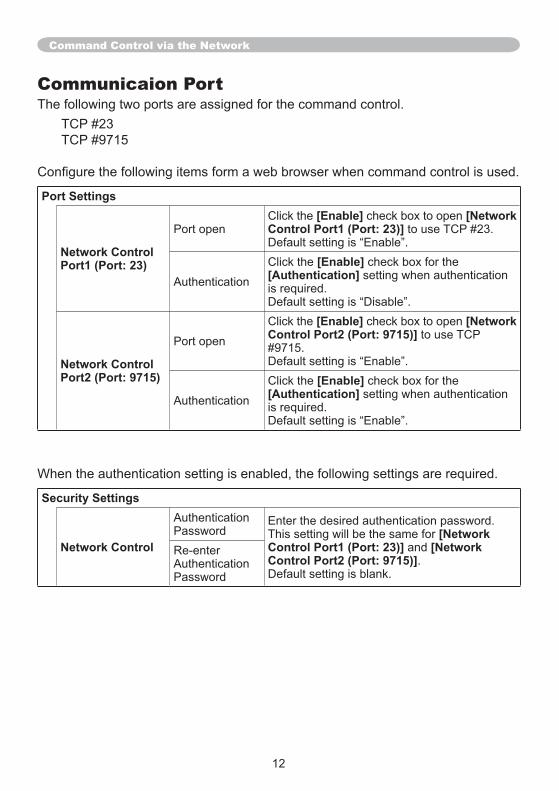
Communicaion Port
Port Settings
Network Control Port1 (Port: 23)
[Enable] [Network Control Port1 (Port: 23)]
[Enable][Authentication]
Network Control Port2 (Port: 9715)
[Enable] [Network Control Port2 (Port: 9715)]
[Enable] [Authentication]
Command Control via the Network
Security Settings
Network Control[Network
Control Port1 (Port: 23)] [NetworkControl Port2 (Port: 9715)]
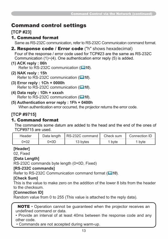
13
Command Control via the Network (continued)
Command control settings[TCP #23]1. Command format
2. Response code / Error code
(1) ACK reply : 06h10
(2) NAK reoly : 15h10
(3) Error reply : 1Ch + 0000h10
(4) Data reply : 1Dh + xxxxh10
(5) Authentication error reply : 1Fh + 0400h
[TCP #9715]1. Command format
[Header]
[Data Length]
[RS-232C commands]10
[Check Sum]
[Connection ID]
NOTE
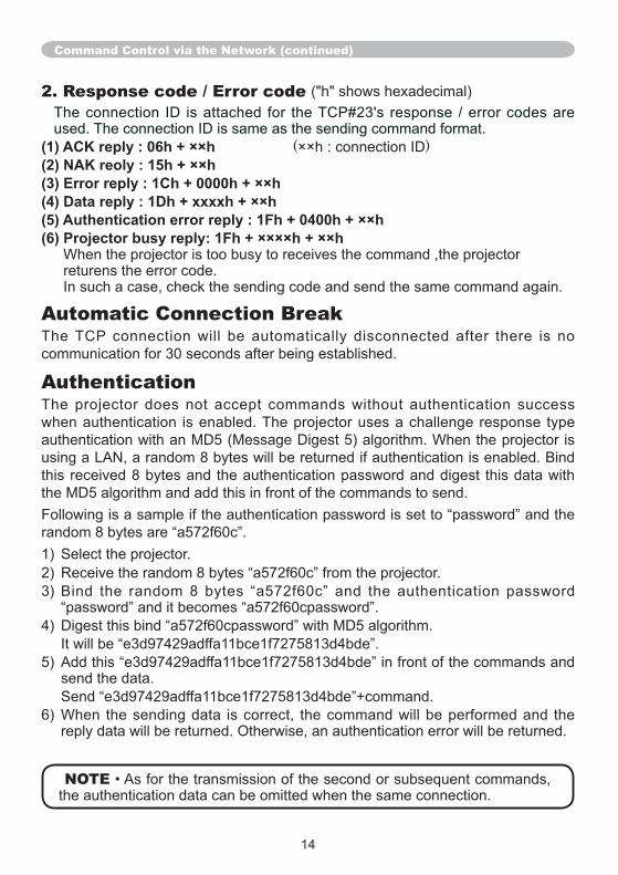
2. Response code / Error code
(1) ACK reply : 06h + ××h ( )(2) NAK reoly : 15h + ××h(3) Error reply : 1Ch + 0000h + ××h(4) Data reply : 1Dh + xxxxh + ××h(5) Authentication error reply : 1Fh + 0400h + ××h(6) Projector busy reply: 1Fh + ××××h + ××h
Automatic Connection Break
Authentication
NOTE
Command Control via the Network (continued)
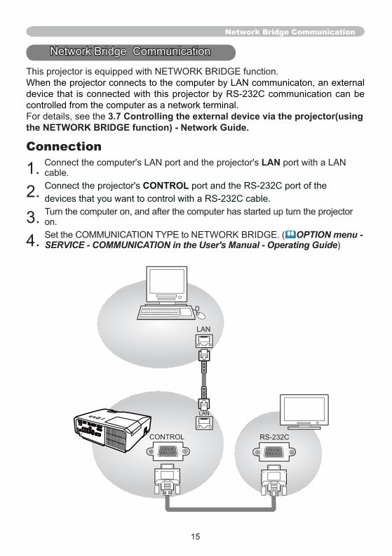
15
3.7 Controlling the external device via the projector(using the NETWORK BRIDGE function) - Network Guide.
ConnectionLAN
CONTROL
OPTION menu - SERVICE - COMMUNICATION in the User's Manual - Operating Guide
Network Bridge Communication
LAN
CONTROL
LAN
RS-232C
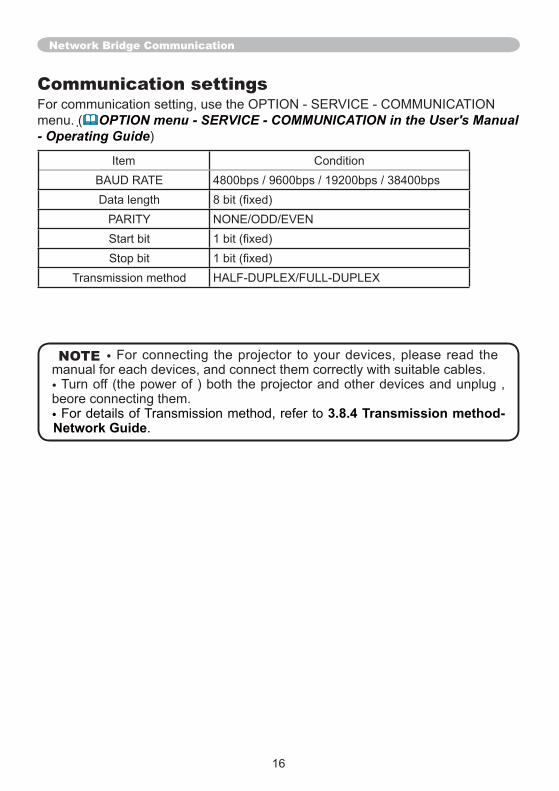
Communication settings
OPTION menu - SERVICE - COMMUNICATION in the User's Manual - Operating Guide
NOTE
3.8.4 Transmission method-Network Guide
Network Bridge Communication
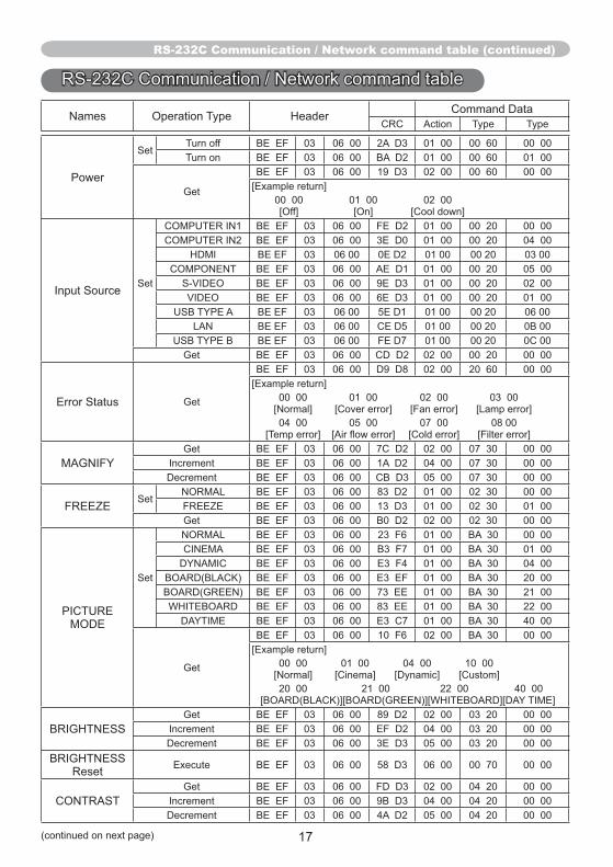
17
RS-232C Communication / Network command table (continued)
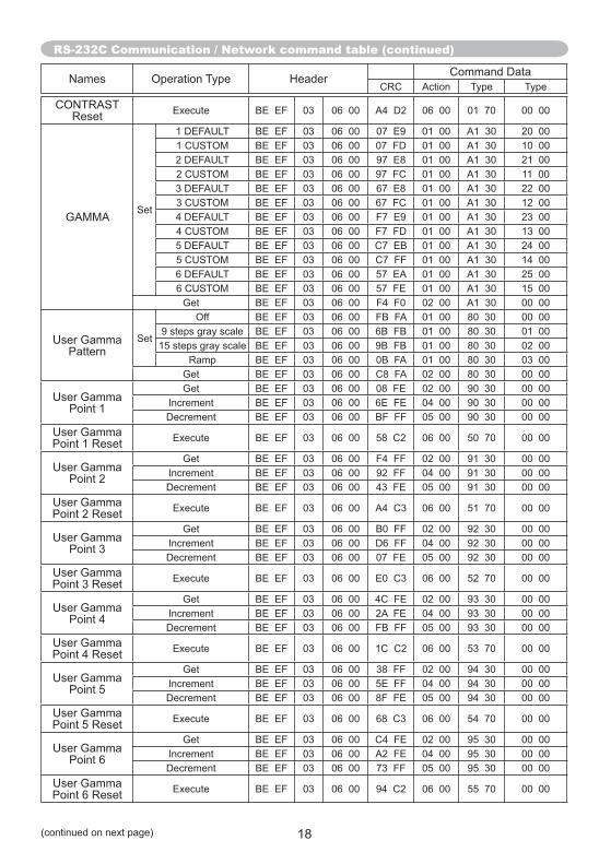
RS-232C Communication / Network command table (continued)
18
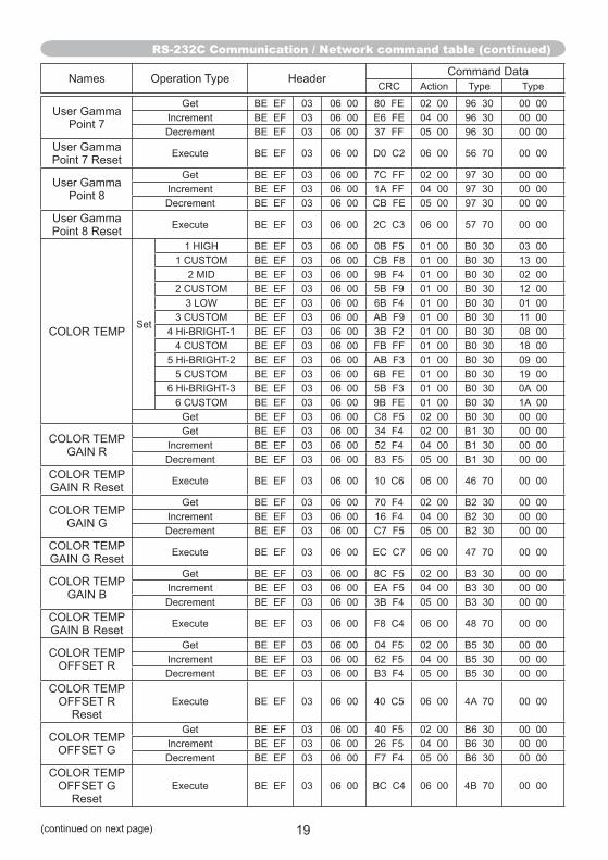
RS-232C Communication / Network command table (continued)
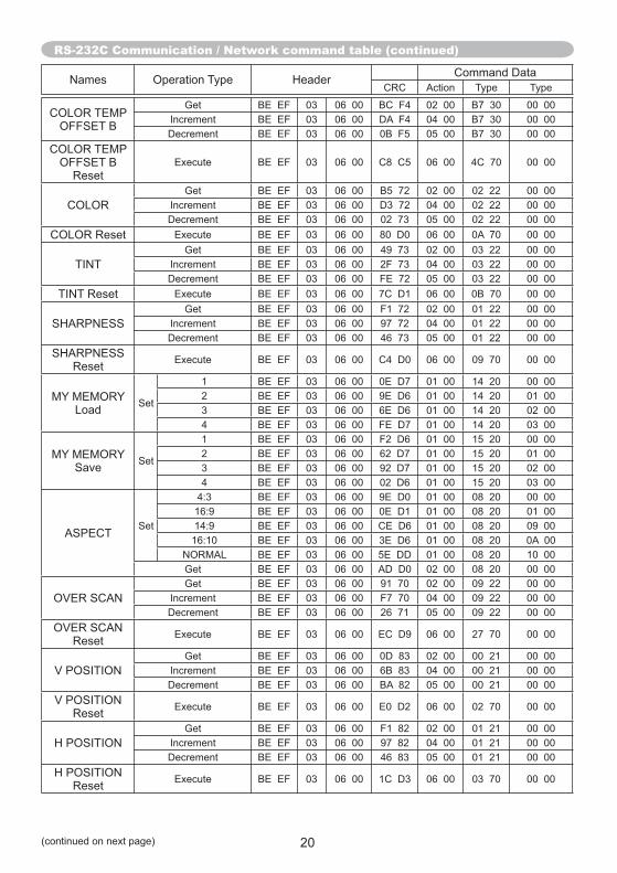
RS-232C Communication / Network command table (continued)
1
3
1
3
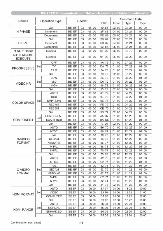
RS-232C Communication / Network command table (continued)
85 73
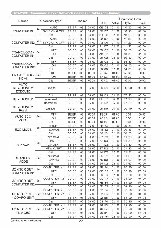
RS-232C Communication / Network command table (continued)
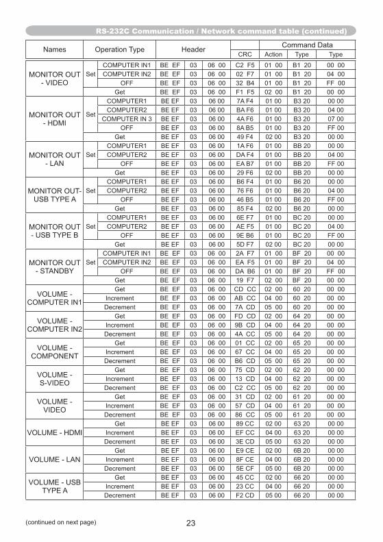
RS-232C Communication / Network command table (continued)
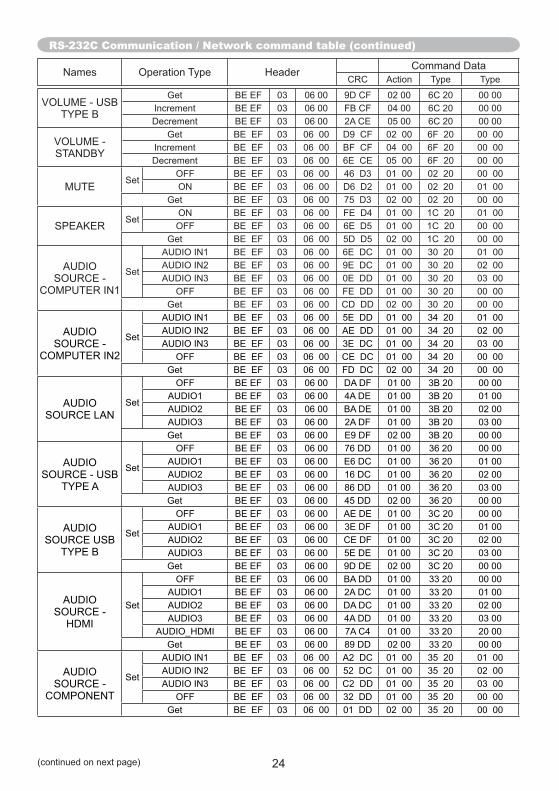
RS-232C Communication / Network command table (continued)
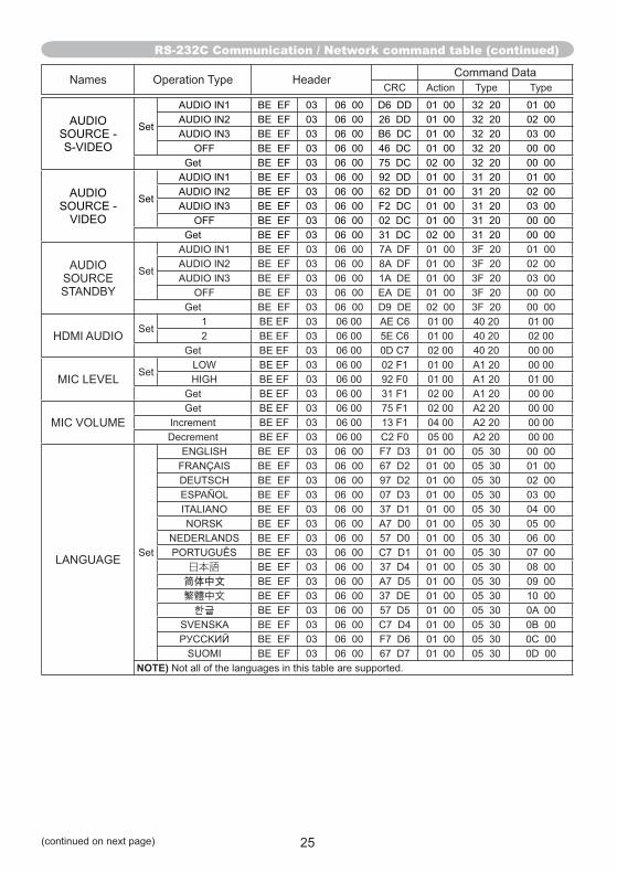
RS-232C Communication / Network command table (continued)
1
NOTE)
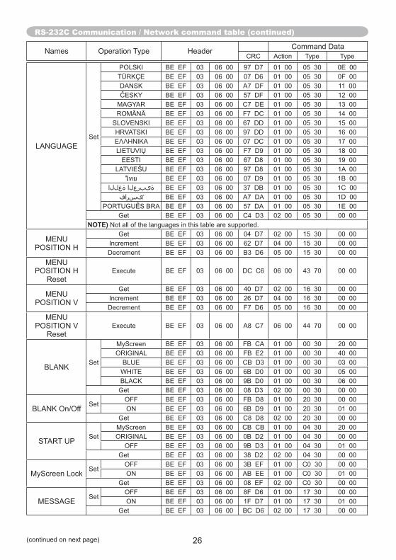
RS-232C Communication / Network command table (continued)
NOTE)
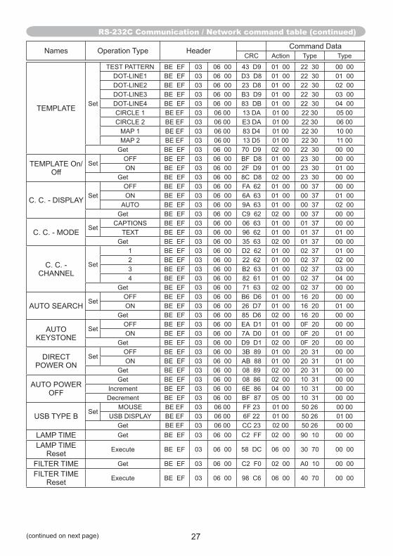
RS-232C Communication / Network command table (continued)
1
3
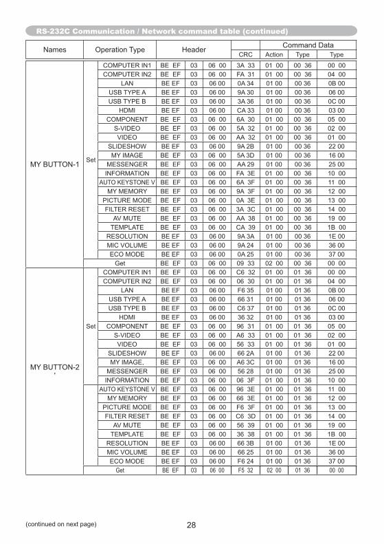
RS-232C Communication / Network command table (continued)RS-232C Communication / Network command table (continued)
Get BE EF 03 06 00 F5 32 02 00 01 36 00 00
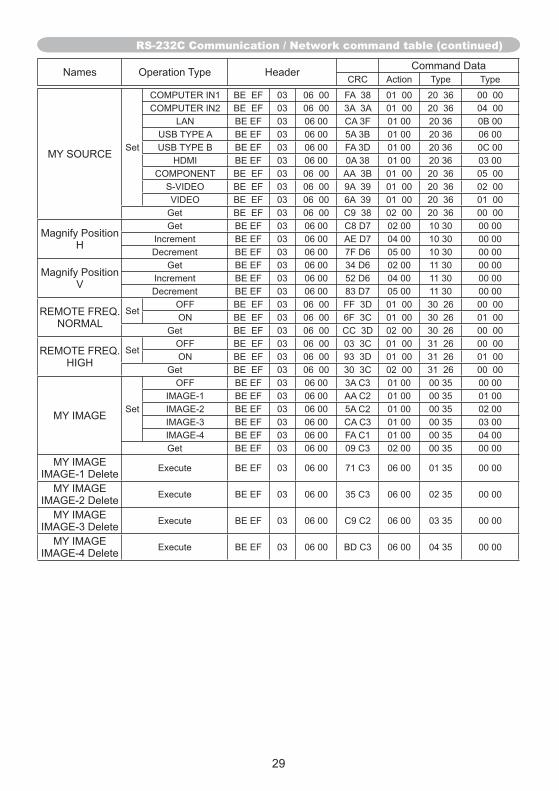
RS-232C Communication / Network command table (continued)RS-232C Communication / Network command table (continued)
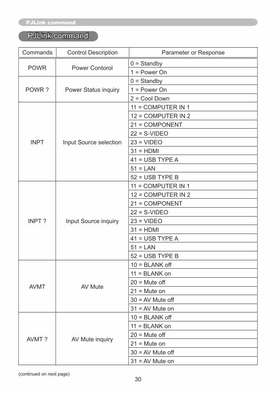
PJLink command
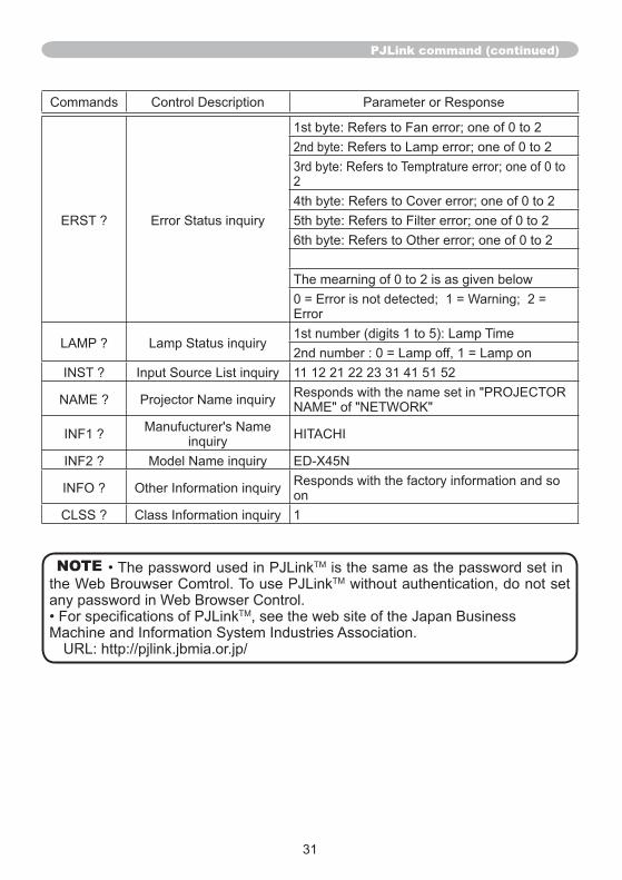
31
PJLink command (continued)
1
NOTE TM
TM
TM

lT c
a
c


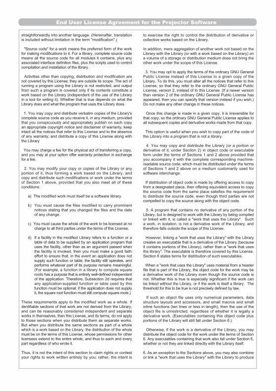
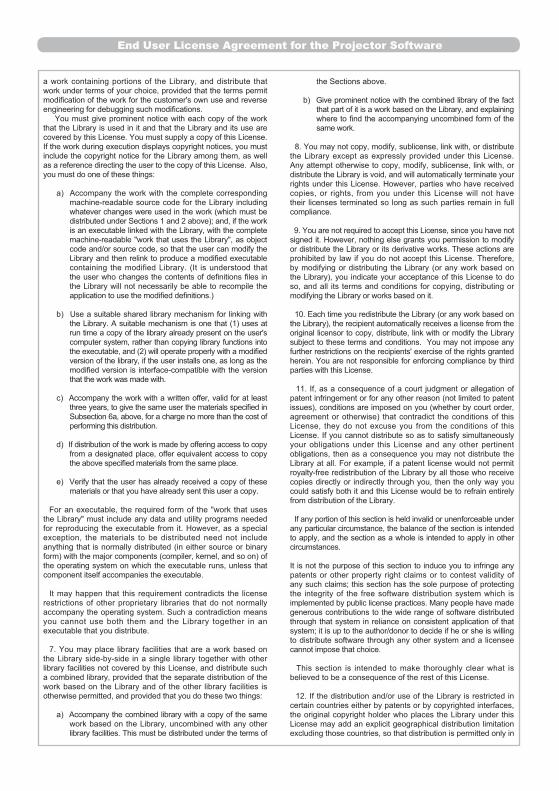


HITACHI EUROPE LTD.
UNITED KINGDOM
Consumer Affairs DepartmentPO Box 3007MaidenheadBerkshire SL6 8ZE
Tel: 0870 405 4405Email:
HITACHI EUROPE GmbH
GERMANY
HITACHI EUROPE S.r.l.
HITACHI EUROPE S.A.S
FRANCE
Munich OfficeDornacher Strasse 3D-85622 Feldkirchen bei München
Tel: 089-991 80-0Fax: 089 - 991 80 -224Hotline: 0180 - 551 25 51 (12ct/min.)Email:
Via T. Gulli n.3920147 MILAN
Tel: 02 487861Fax: 02 48786381Servizio ClientiTel. 02 38073415Email:
Lyon OfficeB.P. 45, 69671 Bron Cedex
Tel: 04 72 14 29 70Fax: 04 72 14 29 99Email:
ITALY
HITACHI EUROPE S.A.
GREECE
HITACHI EUROPE S.A.
HITACHI EUROPE AB
SWEDEN
HITACHI EUROPE LTD.
NORWAY
364, Kifissias Ave. & 1, Delfon Str.152 33 ChalandriAthens
Tel: 1-6837200Fax: 1-6835694Email:
Gran Via Carles III, 86 Planta 5ªEdificios Trade - Torre Este08028 Barcelona
Tel: 93 409 2550Fax: 93 491 3513Email:
Box 77S-164 94 KISTA
Tel: 08 562 711 00Fax: 08 562 711 11Email:
Norwegian Branch OfficeStrandveien 181366 Dysaker
Tel: 02205 9060Fax: 02205 9061Email
SPAIN
HITACHI EUROPE LTD.
BELGIUM
Benelux Branche OfficeBergensesteenweg 4211600 Sint-Pieters-Leeuw
TEL : 0032/2 363 99 01FAX: 0032/2 363 99 00Email : [email protected]
www.hitachidigitalmedia.com
Hitachi, Ltd.Consumer Business Group
Shin-Otemachi Bldg 5f, 2-1, Otemachi 2-Chome,Chiyoda-Ku, Tokyo 100-0004 Japan