ecureuil as355 - tigermms.tiger.tw/upload/2009-12/20091291775.pdf · this ecureuil is designed for...
TRANSCRIPT
JK6028
This kit is guaranteed to be free from defects in material and workmanship at the date of purchase.
It does not cover any damage caused by use or modification. The warranty does not extend
beyond the product itself and is limited only to the original cost of the kit. By the act of building this
user-assembled kit, the user accepts all resulting in liability for damage caused by the final
product. If the buyer is not prepared to accept this liability, it can be returned new and unused to
the place of purchase for a refund.
Warranty
Notice: Adult Supervision Required
This is not a toy. Assembly and flying of this product requires adult supervision.
Read through this book completely and become familiar with the assembly and flight of this
Ecureuil. Inspect all parts for completeness and damage. Browse www.thundertiger.com for
customer service if you encounter any problems.
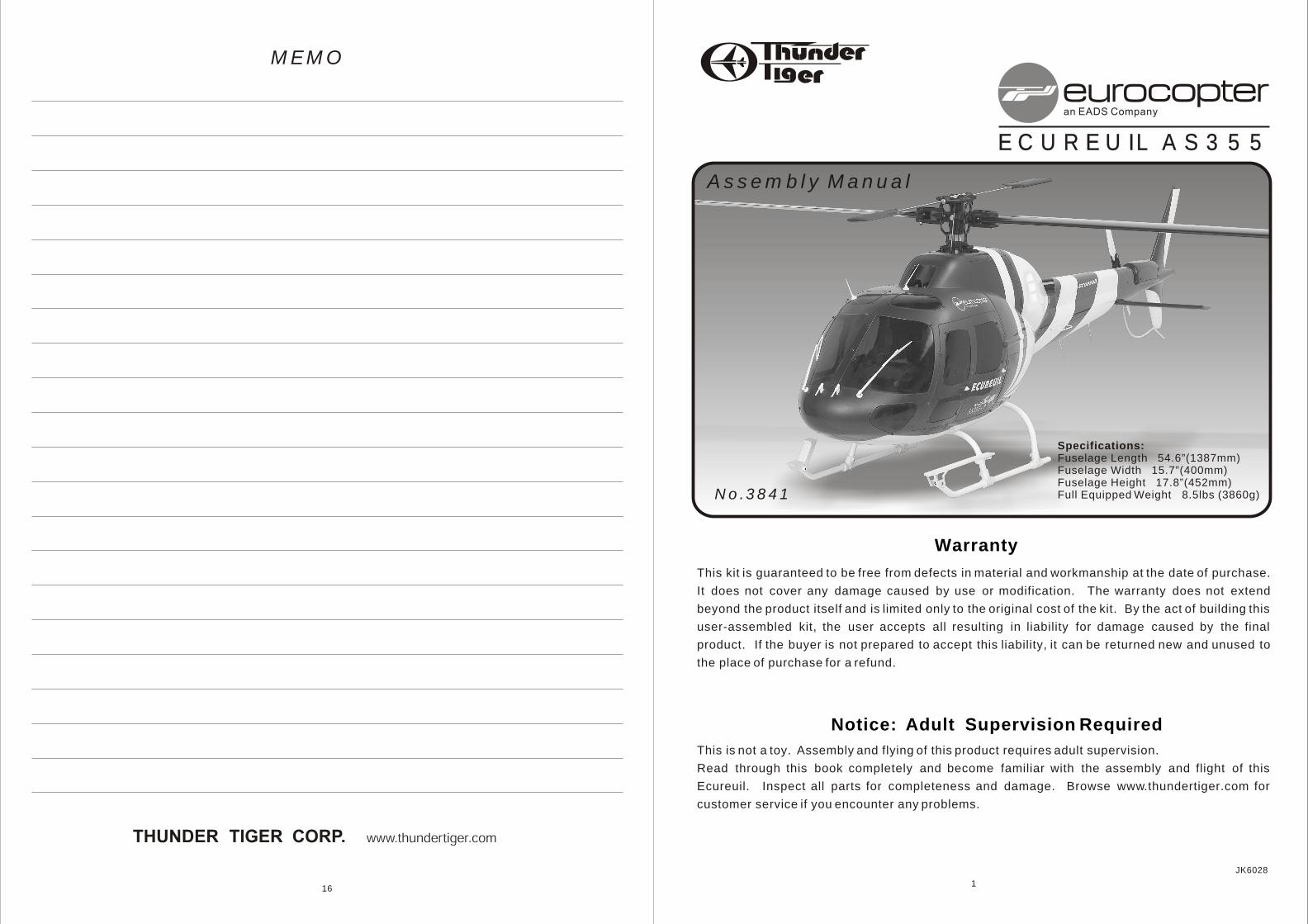
No.3841
MEMO
16
Assembly Manual
1
Specifications:Fuselage Length 54.6”(1387mm)Fuselage Width 15.7”(400mm) Fuselage Height 17.8”(452mm)Full Equipped Weight 8.5lbs (3860g)
ECUREUIL AS355ECUREUIL AS355
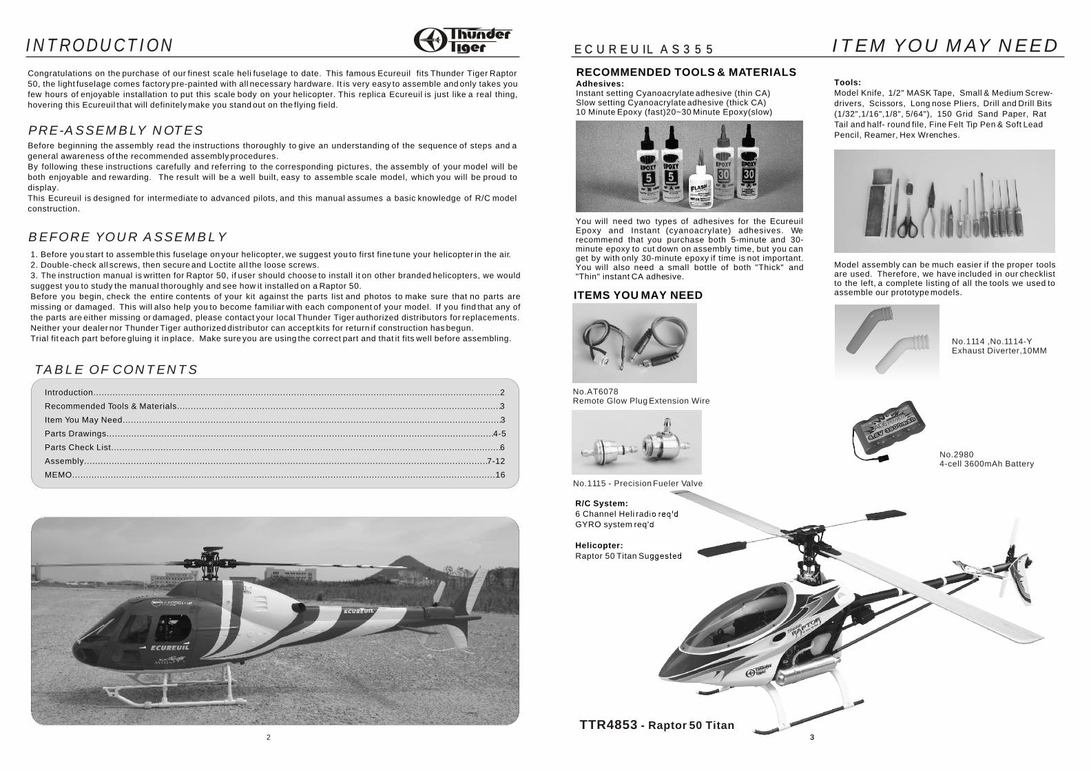
R/C System:
6 Channel Heli radio req'd
GYRO system req'd
Helicopter:
Raptor 50 Titan Suggested
TTR4853 - Raptor 50 Titan3
Before beginning the assembly read the instructions thoroughly to give an understanding of the sequence of steps and a
general awareness of the recommended assembly procedures.
By following these instructions carefully and referring to the corresponding pictures, the assembly of your model will be
both enjoyable and rewarding. The result will be a well built, easy to assemble scale model, which you will be proud to
display.
This Ecureuil is designed for intermediate to advanced pilots, and this manual assumes a basic knowledge of R/C model
construction.
PRE-ASSEMBLY NOTES
1. Before you start to assemble this fuselage on your helicopter, we suggest you to first fine tune your helicopter in the air.
2. Double-check all screws, then secure and Loctite all the loose screws.
3. The instruction manual is written for Raptor 50, if user should choose to install it on other branded helicopters, we would
suggest you to study the manual thoroughly and see how it installed on a Raptor 50.
Before you begin, check the entire contents of your kit against the parts list and photos to make sure that no parts are
missing or damaged. This will also help you to become familiar with each component of your model. If you find that any of
the parts are either missing or damaged, please contact your local Thunder Tiger authorized distributors for replacements.
Neither your dealer nor Thunder Tiger authorized distributor can accept kits for return if construction has begun.
Trial fit each part before gluing it in place. Make sure you are using the correct part and that it fits well before assembling.
BEFORE YOUR ASSEMBLY
Adhesives:Instant setting Cyanoacrylate adhesive (thin CA)Slow setting Cyanoacrylate adhesive (thick CA)10 Minute Epoxy (fast)20~30 Minute Epoxy(slow)
RECOMMENDED TOOLS & MATERIALSTools:
Model Knife, 1/2" MASK Tape, Small & Medium Screw-
drivers, Scissors, Long nose Pliers, Drill and Drill Bits
(1/32",1/16",1/8", 5/64"), 150 Grid Sand Paper, Rat
Tail and half- round file, Fine Felt Tip Pen & Soft Lead
Pencil, Reamer, Hex Wrenches.
You will need two types of adhesives for the Ecureuil Epoxy and Instant (cyanoacrylate) adhesives. We recommend that you purchase both 5-minute and 30-minute epoxy to cut down on assembly time, but you can get by with only 30-minute epoxy if time is not important. You will also need a small bottle of both "Thick" and "Thin" instant CA adhesive.
Model assembly can be much easier if the proper tools are used. Therefore, we have included in our checklist to the left, a complete listing of all the tools we used to assemble our prototype models. ITEMS YOU MAY NEED
TABLE OF CONTENTS
Introduction....................................................................................................................................................2
Recommended Tools & Materials......................................................................................................................3
Item You May Need..........................................................................................................................................3
Parts Drawings.............................................................................................................................................4-5
Parts Check List..............................................................................................................................................6
Assembly...................................................................................................................................................7-12
MEMO..........................................................................................................................................................16
32
Congratulations on the purchase of our finest scale heli fuselage to date. This famous Ecureuil fits Thunder Tiger Raptor
50, the light fuselage comes factory pre-painted with all necessary hardware. It is very easy to assemble and only takes you
few hours of enjoyable installation to put this scale body on your helicopter. This replica Ecureuil is just like a real thing,
hovering this Ecureuil that will definitely make you stand out on the flying field.
No.1114 ,No.1114-Y Exhaust Diverter,10MM
No.AT6078 Remote Glow Plug Extension Wire
INTRODUCTION
No.2980 4-cell 3600mAh Battery
ITEM YOU MAY NEED
No.1115 - Precision Fueler Valve
ECUREUIL AS355ECUREUIL AS355
Front Fuselage (1)Rear Fuselage (1)
2x8mmWood Screw (16) Horizontal Tail (1)
Exhaust Pipe (2)
Tail Transmission Case Cover (1)
PV6039 Fuselage
PV6040 Windshield
Front Windshield (1) Front Window L/1,R/1
Rear Window L/1,R/1Sunroof L/1,R/1
Front Lower Window L/1,R/1Bottom Window L/1,R/1
Air Inlet L/1,R/1 2x5mm Wood Screw (52)
3x23mmSocket Screw (2)
Battery Tray (1)
Rubber Band (2)
Doubler (16)
PV6041 Decoration Set
Wiper (2)
L/F Antenna (2)
H/F Antenna (4)
Tail Skid (1)
PV6042 Foam Retainer
Tail BoomFoam Retainer (1)
PV6043 Retaining Set
Post (2) Silicon Grommet (2)3x10mm
Washer Screw (2)
M2 Nut (2)
PV6044 Landing Skid
Brace A (1) Brace B (1) Skid Pipe (2)
Wiper Strut (2)
Pitot Tube (2)
Skid Adaptor (F,2)
Skid Joiner (4) Skid PipeEnd Cap (2) M3 Locknut (5)
3x4mm Setscrew (10)
Front Mounting Strip (2) Step Bar (1)
Step Ladder (1)
Skid Adaptor (R,2)
Step BarRetainer (1) Foam Tape (8)
Wiper Mount (2)
Handlebar (4) LED (1)RetainingCollar (18)
2x6mm Screw (2)
2.3x12mm WasherWood Screw (1)
3x15mmSelf-tapping
Screw (4)
2x5mm Wood Screw (1)
3x15mmScrew (1)
3x30mmSocket Screw (2)
3x14mmSocket Screw (2)
3x20mmSelf-tapping
Screw (4)
Plastic Tube(1)
Rear MountingStrip (L/1,R/1)
54
PARTS DRAWINGS PARTS DRAWINGSECUREUIL AS355ECUREUIL AS355
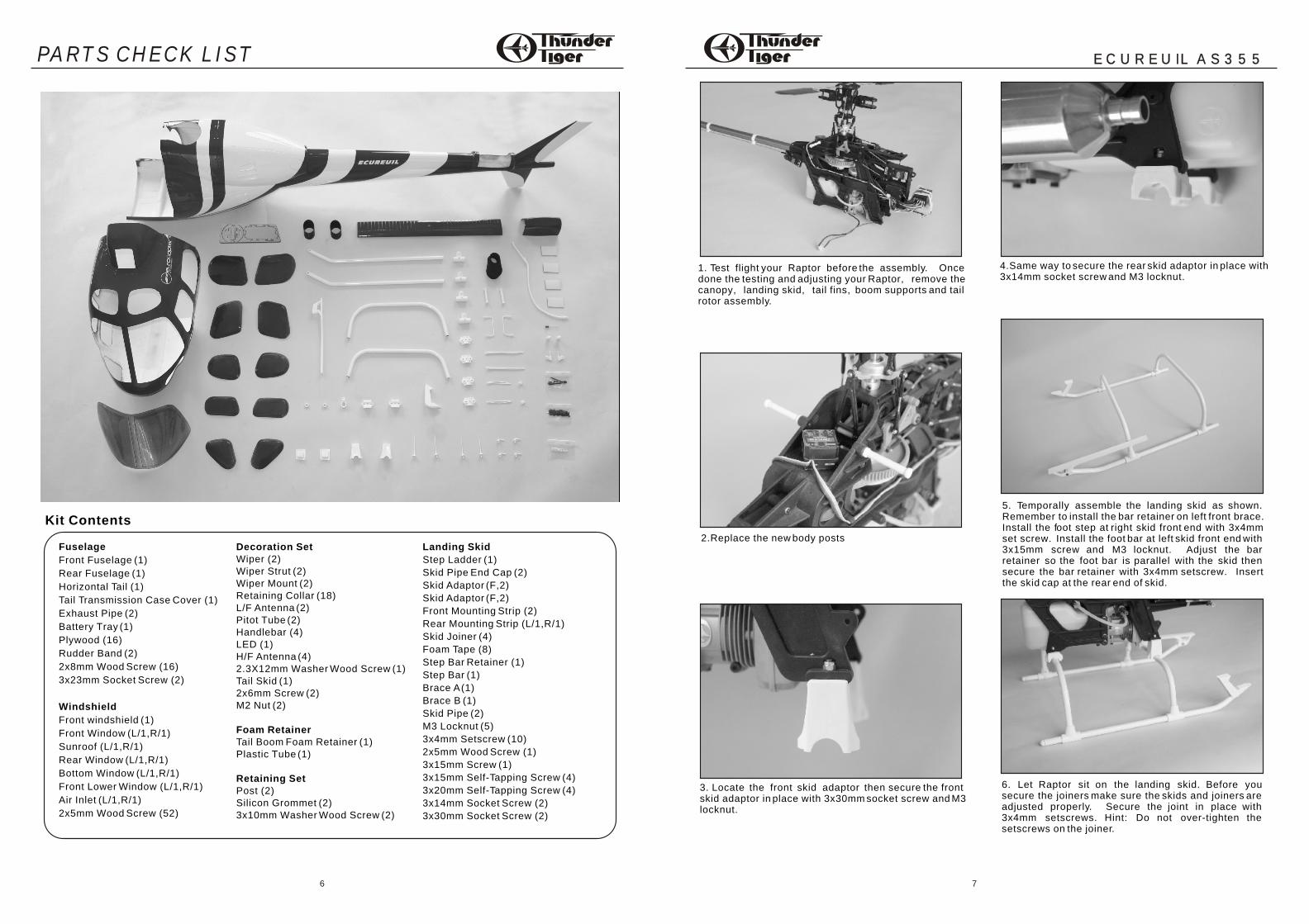
1. Test flight your Raptor before the assembly. Oncedone the testing and adjusting your Raptor, remove thecanopy, landing skid, tail fins, boom supports and tailrotor assembly.
2.Replace the new body posts
3. Locate the front skid adaptor then secure the frontskid adaptor in place with 3x30mm socket screw and M3locknut.
4.Same way to secure the rear skid adaptor in place with3x14mm socket screw and M3 locknut.
5. Temporally assemble the landing skid as shown. Remember to install the bar retainer on left front brace. Install the foot step at right skid front end with 3x4mm set screw. Install the foot bar at left skid front end with 3x15mm screw and M3 locknut. Adjust the bar retainer so the foot bar is parallel with the skid then secure the bar retainer with 3x4mm setscrew. Insert the skid cap at the rear end of skid.
6. Let Raptor sit on the landing skid. Before you secure the joiners make sure the skids and joiners are adjusted properly. Secure the joint in place with 3x4mm setscrews. Hint: Do not over-tighten the setscrews on the joiner.
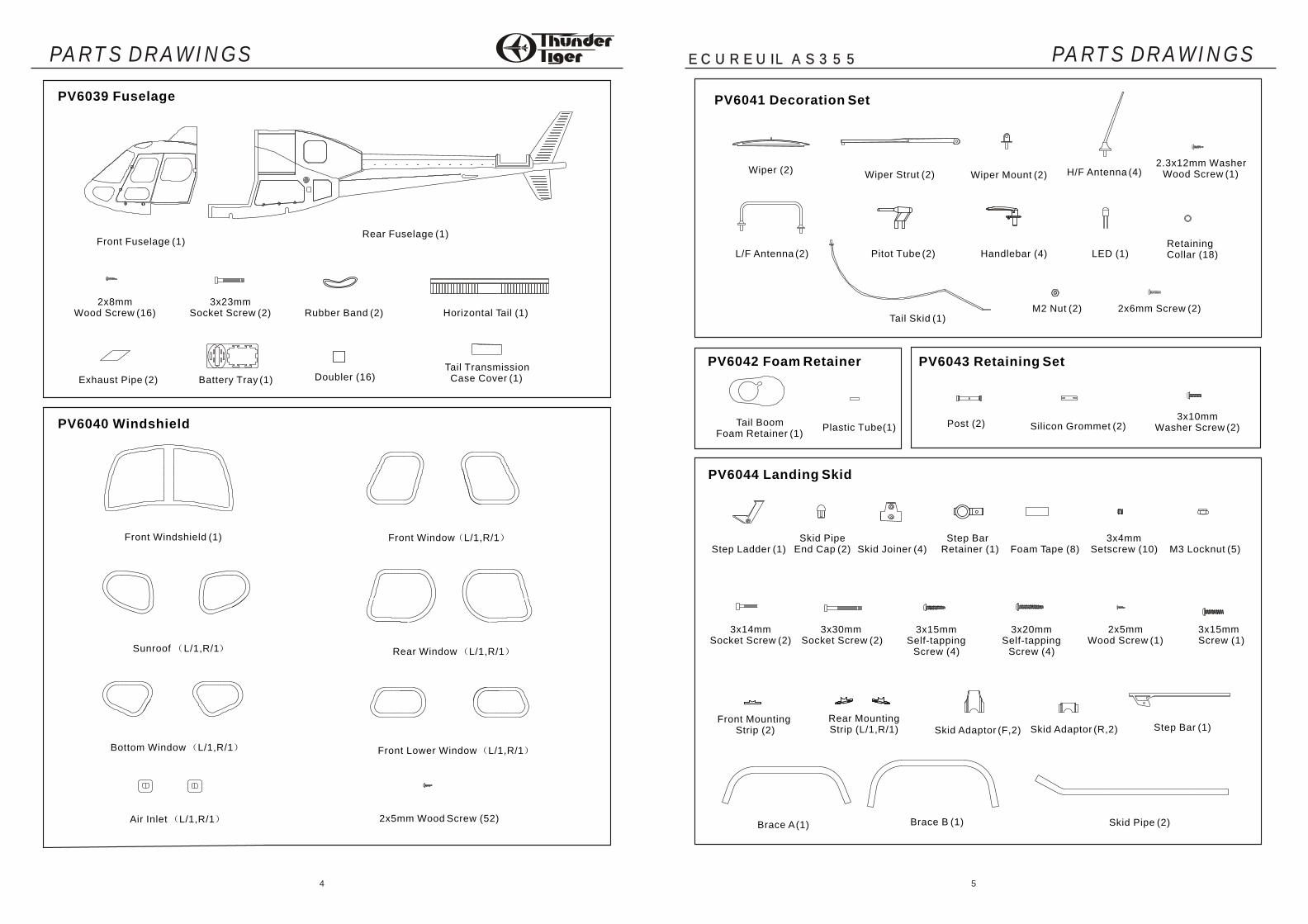
Fuselage
Front Fuselage (1)
Rear Fuselage (1)
Horizontal Tail (1)
Tail Transmission Case Cover (1)
Exhaust Pipe (2)
Battery Tray (1)
Plywood (16)
Rudder Band (2)
2x8mm Wood Screw (16)
3x23mm Socket Screw (2)
Windshield
Front windshield (1)
Front Window (L/1,R/1)
Sunroof (L/1,R/1)
Rear Window (L/1,R/1)
Bottom Window (L/1,R/1)
Front Lower Window (L/1,R/1)
Air Inlet (L/1,R/1)
2x5mm Wood Screw (52)
Landing Skid
Step Ladder (1)
Skid Pipe End Cap (2)
Skid Adaptor (F,2)
Skid Adaptor (F,2)
Front Mounting Strip (2)
Rear Mounting Strip (L/1,R/1)
Skid Joiner (4)
Foam Tape (8)
Step Bar Retainer (1)
Step Bar (1)
Brace A (1)
Brace B (1)
Skid Pipe (2)
M3 Locknut (5)
3x4mm Setscrew (10)
2x5mm Wood Screw (1)
3x15mm Screw (1)
3x15mm Self-Tapping Screw (4)
3x20mm Self-Tapping Screw (4)
3x14mm Socket Screw (2)
3x30mm Socket Screw (2)
Decoration SetWiper (2)Wiper Strut (2)Wiper Mount (2)Retaining Collar (18)L/F Antenna (2)Pitot Tube (2)Handlebar (4)LED (1)H/F Antenna (4)2.3X12mm Washer Wood Screw (1)Tail Skid (1)2x6mm Screw (2)M2 Nut (2)
Foam RetainerTail Boom Foam Retainer (1)Plastic Tube (1)
Retaining SetPost (2)Silicon Grommet (2)3x10mm Washer Wood Screw (2)
Kit Contents
76
PARTS CHECK LIST ECUREUIL AS355ECUREUIL AS355
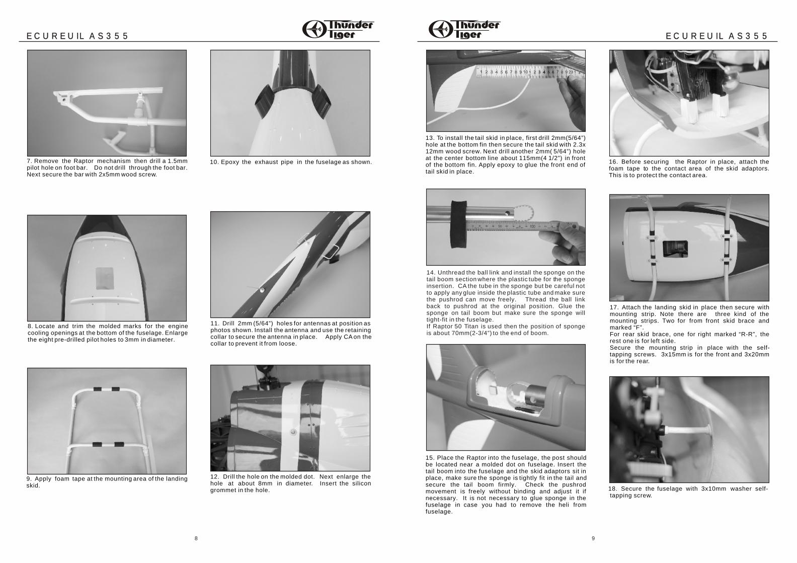
7. Remove the Raptor mechanism then drill a 1.5mmpilot hole on foot bar. Do not drill through the foot bar. Next secure the bar with 2x5mm wood screw.
8. Locate and trim the molded marks for the enginecooling openings at the bottom of the fuselage. Enlargethe eight pre-drilled pilot holes to 3mm in diameter.
9. Apply foam tape at the mounting area of the landingskid.
10. Epoxy the exhaust pipe in the fuselage as shown.
11. Drill 2mm (5/64”) holes for antennas at position asphotos shown. Install the antenna and use the retainingcollar to secure the antenna in place. Apply CA on the collar to prevent it from loose.
12. Drill the hole on the molded dot. Next enlarge thehole at about 8mm in diameter. Insert the silicongrommet in the hole.
13. To install the tail skid in place, first drill 2mm(5/64”) hole at the bottom fin then secure the tail skid with 2.3x 12mm wood screw. Next drill another 2mm( 5/64”) hole at the center bottom line about 115mm(4 1/2”) in front of the bottom fin. Apply epoxy to glue the front end of tail skid in place.
14. Unthread the ball link and install the sponge on the tail boom section where the plastic tube for the sponge insertion. CA the tube in the sponge but be careful not to apply any glue inside the plastic tube and make sure the pushrod can move freely. Thread the ball link back to pushrod at the original position. Glue the sponge on tail boom but make sure the sponge will tight-fit in the fuselage. If Raptor 50 Titan is used then the position of sponge is about 70mm(2-3/4”) to the end of boom.
15. Place the Raptor into the fuselage, the post should be located near a molded dot on fuselage. Insert the tail boom into the fuselage and the skid adaptors sit in place, make sure the sponge is tightly fit in the tail and secure the tail boom firmly. Check the pushrod movement is freely without binding and adjust it if necessary. It is not necessary to glue sponge in the fuselage in case you had to remove the heli from fuselage.
16. Before securing the Raptor in place, attach the foam tape to the contact area of the skid adaptors. This is to protect the contact area.
17. Attach the landing skid in place then secure with mounting strip. Note there are three kind of the mounting strips. Two for from front skid brace and marked “F”.For rear skid brace, one for right marked “R-R”, the rest one is for left side.Secure the mounting strip in place with the self-tapping screws. 3x15mm is for the front and 3x20mm is for the rear.
18. Secure the fuselage with 3x10mm washer self- tapping screw.
98
ECUREUIL AS355ECUREUIL AS355ECUREUIL AS355ECUREUIL AS355
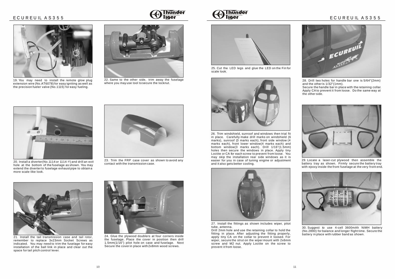
19. You may need to install the remote glow plugextension wire (No.AT6078) for easy igniting as well asthe precision fueler valve (No.1115) for easy fueling.
20. Install a diverter(No.1114 or 1114-Y) and drill an exithole at the bottom of the fuselage as shown. You mayextend the diverter to fuselage exhaust pipe to obtain amore scale-like look.
21. Install the tail transmission case and tail rotor, remember to replace 3x23mm Socket Screws as indicated. You may need to trim the fuselage for easy installation of the ball link in place and clear out the space for tail pitch control lever.
22. Same to the other side, trim away the fuselagewhere you may use tool to secure the locknut.
23. Trim the FRP case cover as shown to avoid anycontact with the transmission case.
24. Glue the plywood doublers at four corners inside the fuselage. Place the cover in position then drill 1.5mm(1/16”) pilot hole on case and fuselage. Next Secure the cover in place with 2x8mm wood screws.
25. Cut the LED legs and glue the LED on the Fin forscale look.
26. Trim windshield, sunroof and windows then trial fit in place. Carefully make drill marks on windshield (6 marks), sunroof (3 marks each), front side window (4 marks each), front lower window(4 marks each) and bottom window(3 marks each). Drill 1/16”(1.5mm) holes then secure the windows in place. Apply tiny Loctite or CA for each screw to prevent from loose. You may skip the installation rear side windows as it is easier for you in case of tuning engine or adjustment and it also gets better cooling.
27. Install the fittings as shown includes wiper, pitot tube, antenna. Drill 2mm hole and use the retaining collar to hold the fitting in place. After adjusting the fitting properly, apply tiny CA on the collar to prevent it loosed. For wiper, secure the strut on the wiper mount with 2x6mm screw and M2 nut. Apply Loctite on the screw to prevent it from loose.
28. Drill two holes for handle bar one is 5/64”(2mm) and the other is 1/32”(1mm).Secure the handle bar in place with the retaining collar. Apply CA to prevent it from loose. Do the same way at the other side.
29. Locate a laser-cut plywood then assemble thebattery tray as shown. Firmly secure the battery traywith epoxy inside the front fuselage at the very front end.
30. Suggest to use 4-cell 3600mAh NiMH battery(No.2890) for balance and longer flight time. Secure thebattery in place with rubber band as shown.
1110
ECUREUIL AS355ECUREUIL AS355ECUREUIL AS355ECUREUIL AS355
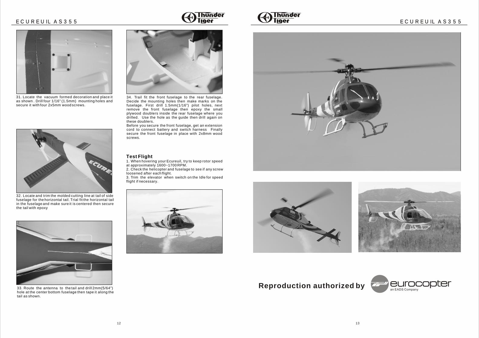
31. Locate the vacuum formed decoration and place itas shown . Drill four 1/16" (1.5mm) mounting holes andsecure it with four 2x5mm wood screws.
32. Locate and trim the molded cutting line at tail of sidefuselage for the horizontal tail. Trial fit the horizontal tailin the fuselage and make sure it is centered then securethe tail with epoxy
33. Route the antenna to the tail and drill 2mm(5/64”)hole at the center bottom fuselage then tape it along thetail as shown.
34. Trail fit the front fuselage to the rear fuselage. Decide the mounting holes then make marks on the fuselage. First drill 1.5mm(1/16”) pilot holes, next remove the front fuselage then epoxy the small plywood doublers inside the rear fuselage where you drilled. Use the hole as the guide then drill again on these doublers.Before you secure the front fuselage, get an extension cord to connect battery and switch harness Finally secure the front fuselage in place with 2x8mm wood screws.
Test Flight1. When hovering your Ecureuil, try to keep rotor speedat approximately 1600~1700 RPM. 2. Check the helicopter and fuselage to see if any screwloosened after each flight.3. Trim the elevator when switch on the Idle for speedflight if necessary.
1312
ECUREUIL AS355ECUREUIL AS355ECUREUIL AS355ECUREUIL AS355
Reproduction authorized by
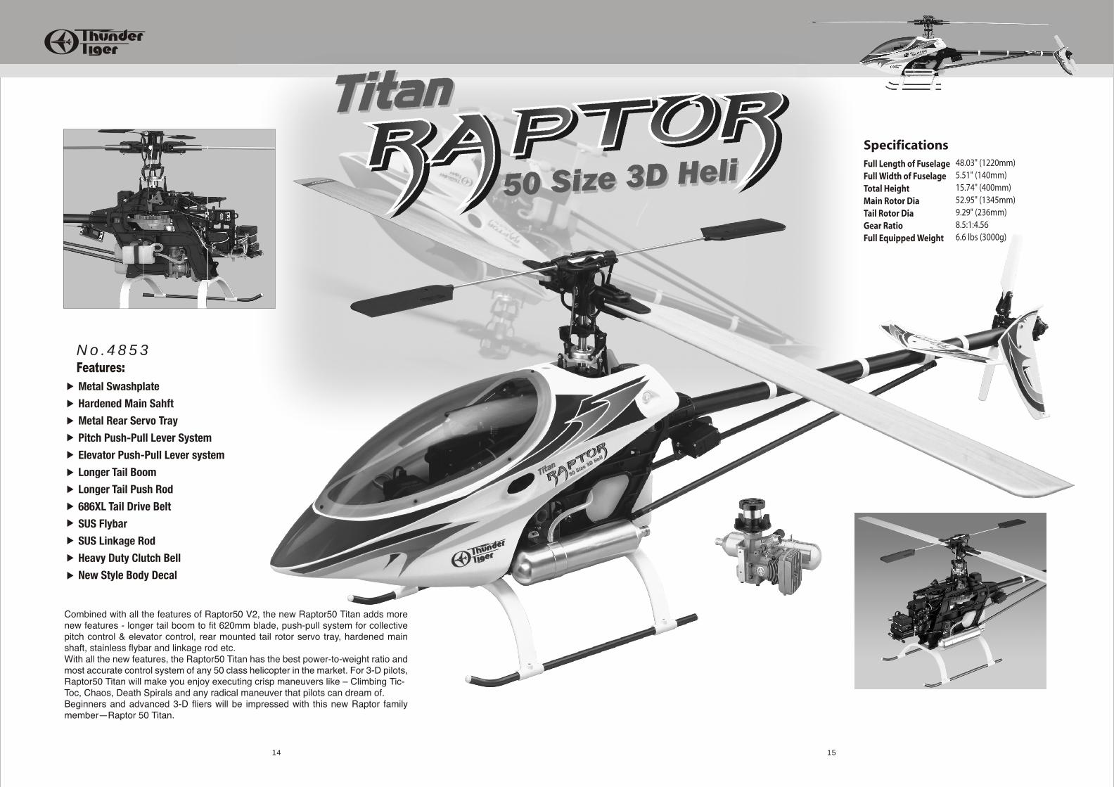
No.4853
1514