ection 5: concrete structures california amendments to ... · section 5: concrete structures...
TRANSCRIPT

SECTION 5: CONCRETE STRUCTURES CALIFORNIA AMENDMENTS TO AASHTO LRFD BRIDGE DESIGN SPECIFICATIONS – FOURTH EDITION 5-2A
November 2011
Add the following Definitions to Article 5.2: Duct Stack – A vertical group of tendons in which the space between individual tendons is less than 1.5 in.
Local Bending – The lateral flexural bending caused by curved post-tensioning tendons on the concrete cover between the internal ducts and the inside face of the curved element (usually webs).
Local Shear – The lateral shear caused by curved post-tensioning tendons on the concrete cover between the internal ducts and the inside face of the curved element (usually web).
Regional Bending – Transverse bending of a concrete box girder web due to concentrated lateral prestress forces resisted by the frame action of the box acting as a whole.
Resal Effect – The reduction or addition of shear based on the bottom slab compression angle with the center-of-gravity.
Stirrup and Duct Ties – Reinforcement designed to prevent local bending and/or shear failure of curved post-tensioned tendons cast within a web.

SECTION 5: CONCRETE STRUCTURES CALIFORNIA AMENDMENTS TO AASHTO LRFD BRIDGE DESIGN SPECIFICATIONS – FOURTH EDITION 5-2B
November 2011
This page is intentionally left blank.

SECTION 5: CONCRETE STRUCTURES CALIFORNIA AMENDMENTS TO AASHTO LRFD BRIDGE DESIGN SPECIFICATIONS – FOURTH EDITION 5-6A
November 2011
Add the following Notations to Article 5.3:
effd = One-half the effective length of the failure plane in shear and tension for curved element (in.) (5.10.4.3.1)
ductd = outside diameter of post-tensioning duct (in.) (5.10.4.3.1).
crf = design flexural cracking stress of the hypothetical unreinforced concrete beam consisting of the cover conerete
over the inside face of a stack of horizontally curved post-tensioned tendons (in.-k) (5.10.4.3.1).
ch = clear span of the web of concrete box girder bridges between the top and bottom slabs measured along the axis
of the webs (in.) (C5.10.4.3.1).
dsh = height of a vertical group of ducts (in.) (C5.10.4.3.1).
endM = moment at the ends of a hypothetical unreinforced concrete beam consisting of the cover conerete over the
inside face of a stack of horizontally curved post-tensioned tendons (in.-k) (5.10.4.3.1).
midM = moment at the midpoint of a hypothetical unreinforced concrete beam consisting of the cover conerete over
the inside face of a stack of horizontally curved prestress post-tensioned (in.-k) (5.10.4.3.1).
contφ = girder web continuity factor for evaluating regional bending (5.10.4.3.1).

SECTION 5: CONCRETE STRUCTURES CALIFORNIA AMENDMENTS TO AASHTO LRFD BRIDGE DESIGN SPECIFICATIONS – FOURTH EDITION 5-6B
November 2011
This page is intentionally left blank.

SECTION 5: CONCRETE STRUCTURES CALIFORNIA AMENDMENTS TO AASHTO LRFD BRIDGE DESIGN SPECIFICATIONS – FOURTH EDITION 5-12A
November 2011
5.4.2.1 Compressive Strength Revise the 3rd paragraph as follows:
The specified compressive strength for prestressed concrete and decks shall not be less than 4.0 ksi.
The specified compressive concrete strength shall not be less than 3.6 ksi for reinforced concrete.

SECTION 5: CONCRETE STRUCTURES CALIFORNIA AMENDMENTS TO AASHTO LRFD BRIDGE DESIGN SPECIFICATIONS – FOURTH EDITION 5-12B
November 2011
This page is intentionally left blank.

SECTION 5: CONCRETE STRUCTURES CALIFORNIA AMENDMENTS TO AASHTO LRFD BRIDGE DESIGN SPECIFICATIONS – FOURTH EDITION 5-18A
November 2011
Replace the Article 5.4.2.6 with the following:
Unless determined by physical tests, the modulus of rupture, fr in ksi, for specified concrete strengths up to 15.0 ksi, may be taken as: • For normal-weight concrete:
o Except as specified below …..cf '24.0
o When used to calculate the cracking moment of a member in Article 5.8.3.4.3 ………………....….
cf '20.0
• For lightweight concrete: o For sand-lightweight concrete...
cf '20.0
o For sand-lightweight concrete...cf '17.0
When physical tests are used to determine
modulus of rupture, the tests shall be performed in accordance with AASHTO T 97 and shall be performed on concrete using the same proportions and materials as specified for the structure.
Replace the Article C 5.4.2.6 with the following:
Most modulus of rupture test data on normal weight concrete is between
cf '24.0 and cf '37.0
(ksi) (Walker and Bloem 1960; Khan, Cook and Mitchell 1996). A value of
cf '37.0 has been
recommended for the prediction of the tensile strength of high-strength concrete (ACI 1992). However, the modulus of rupture is sensitive to curing methods, and nearly all of the test units in the dataset mentioned previously were moist cured until testing. Carrasquillio, et al (1981), noted a 26 percent reduction in the 28-day modulus of rupture if high strength units were allowed to dry after 7 days of moist curing over units that were moist cured until testing.
The flexural cracking stress of concrete members has been shown to significantly reduce with increasing member depth. Shioya, et al (1989) observed that the flexural cracking strength is proportional to H -0.25, where H is the overall depth of the flexural member in inches. Based on this observation, a 36.0 inch deep girder should achieve a flexural cracking stress that is 36 percent lower than that of a 6.0 inch deep test specimen.
Since modulus of rupture units were either 4.0 or 6.0 inches deep and moist cured up to the time of testing, the modulus of rupture should be significantly greater than that of an average size bridge member composed of the same concrete. Therefore,
cf '24.0 is appropriate for checking
minimum reinforcement in Article 5.7.3.3.2. The properties of higher strength concrete
are particularly sensitive to the constitutive materials. If test results are to be used in design, it is imperative that tests be made using concrete with not only the same mix proportions, but also the same materials as the concrete used in the structure.
The given values may be unconservative for tensile cracking by restrained shrinkage, anchor zone splitting, and other such tensile forces caused by effects others than flexure. The direct tensile strength stress should be used for these cases.

SECTION 5: CONCRETE STRUCTURES CALIFORNIA AMENDMENTS TO AASHTO LRFD BRIDGE DESIGN SPECIFICATIONS – FOURTH EDITION 5-18B
November 2011
This page is intentionally left blank.

SECTION 5: CONCRETE STRUCTURES CALIFORNIA AMENDMENTS TO AASHTO LRFD BRIDGE DESIGN SPECIFICATIONS – FOURTH EDITION 5-22A
November 2011
5.4.6.2 Size of Ducts Modify the second paragraph:
The size of ducts shall not exceed 0.4 0.5 times the least gross concrete thickness at the duct.

SECTION 5: CONCRETE STRUCTURES CALIFORNIA AMENDMENTS TO AASHTO LRFD BRIDGE DESIGN SPECIFICATIONS – FOURTH EDITION 5-22B
November 2011
This page is intentionally left blank.

SECTION 5: CONCRETE STRUCTURES CALIFORNIA AMENDMENTS TO AASHTO LRFD BRIDGE DESIGN SPECIFICATIONS – FOURTH EDITION 5-23A
November 2011
5.5.3.1 General Revise the 2nd Paragraph as follows:
In regions of compressive stress due to permanent loads and prestress in reinforced and partially prestressed concrete components, fatigue shall be considered only if this compressive stress is less than twice the maximum tensile live load stress resulting from the Ffatigue I load combination for finite fatigue life as specified in Table 3.4.1-1 in combination with the provisions of Article 3.6.1.4.
Insert the following after the 3rd Paragraph:
Where consideration of fatigue is required, the stress range shall be determined using the Fatigue I load combination for infinite fatigue life as specified in Table 3.4.1-1. Revise the 4th Paragraph as follows:
The section properties for fatigue investigations
shall be based on cracked sections where the sum of stresses, due to unfactored permanent loads and prestress, and 1.75 times the fatigue load of Fatigue I is tensile and exceeds
cf '095.0 . 5.5.3.2 Reinforcing Bars
Revise the 1st Paragraph as follows:
The stress range in straight reinforcement and welded wire reinforcement without a cross weld in the high-stress region resulting from the Ffatigue I load combination for infinite fatigue life, specified in Table 3.4.1-1, shall satisfy:
C5.5.3.1
Revise the 2nd Paragraph as follows:
In determining the need to investigate fatigue, Table 3.4.1-1 specifies a load factor of 0.875 on the live load force effect resulting from the fatigue truck. The factor 2.0 specified in this Article is applied to the factored live load for a total of 1.750 times the unfactored force effect from the fatigue truck for infinite fatigue life.

SECTION 5: CONCRETE STRUCTURES CALIFORNIA AMENDMENTS TO AASHTO LRFD BRIDGE DESIGN SPECIFICATIONS – FOURTH EDITION 5-24A
November 2011
5.5.3.3 Prestressing Tendons
Revise the 1st Paragraph as follows: The stress range in prestressing tendons resulting
from the Fatigue I load combination for infinite fatigue life, specified in Table 3.4.1-1, shall not exceed:
5.5.3.4 Welded or Mechanical Splices of Reinforcement
Revise the 1st Paragraph as follows:
For welded or mechanical connections that are subject to repetitive loads, the range of stress, ff, resulting from the Fatigue I load combination for infinite fatigue life, and the Fatigue II load combination for finite fatigue life specified in Table 3.4.1-1, shall not exceed the nominal fatigue resistance given in Table 1. Table 5.5.3.4-1 Nominal Fatigue Resistance of Splices. Revise Table 5.5.3.4-1 as follows: Table 5.5.3.4-1 Nominal Fatigue Resistance of Splices.
Type of Splice
ff for greater
than 1,000,000
cycles Grout-filled sleeve, with or without epoxy coated bar
18 ksi
Cold-swaged coupling sleeves without threaded ends and with or without epoxy-coated bar; Integrally-forged coupler with upset NC threads; Steel sleeve with a wedge; One-piece taper-threaded coupler; and Single V-groove direct butt weld
12 ksi
All other types of splices 4 ksi Revise the 2nd Paragraph as follows:
Where the total cycles of loading, Ncyc, are less than 1 million, nominal fatigue resistance of splices specified in Table 1 .ff may be increased by the quantity 24 (6−logNcyc) ksi to a total not greater than the value of ff given by the right side of Eq. 5.5.3.2-1 in Article 5.5.3.2. Higher values of nominal fatigue resistance ff, up to the value given by the right side of Eq. 5.5.3.2-1, may be used if justified by fatigue test data on splices that are the same as those that will be placed in service.

SECTION 5: CONCRETE STRUCTURES CALIFORNIA AMENDMENTS TO AASHTO LRFD BRIDGE DESIGN SPECIFICATIONS – FOURTH EDITION 5-25A
November 2011
5.5.4.2.1 Conventional Construction
Insert the following under the first bullet: For tension-controlled cast-in-place
prestressed concrete sections and spliced precast girder sections as defined in Article 5.7.2.1………………….…..0.95
Modify the 2nd bullet as follows: For tension-controlled precast prestressed
concrete section as defined in Article 5.7.2.1………………….…..1.00

SECTION 5: CONCRETE STRUCTURES CALIFORNIA AMENDMENTS TO AASHTO LRFD BRIDGE DESIGN SPECIFICATIONS – FOURTH EDITION 5-26A
November 2011
C5.5.4.2.1
Delete Fig. C5.5.4.2.1-1 and replace with the following:
Figure C5.5.4.2.1-1 – Variation of φ with net tensile strain εt for Grade 60 reinforcement and for prestresseding members steel.
0.95 Cast-In-Place or Spliced Post Tensioned Prestressed Members
( )00206766750 ... t −+= εφ
Precast Prestressed Members φ = 0.75 + 83.33(εt – 0.002)
Non Prestressed Members ( )00200050750 ... t −+= εφ

SECTION 5: CONCRETE STRUCTURES CALIFORNIA AMENDMENTS TO AASHTO LRFD BRIDGE DESIGN SPECIFICATIONS – FOURTH EDITION 5-28A
November 2011
5.5.5 Extreme Event Limit State
Revise as follows:
The structure as a whole and its components shall be proportioned to resist collapse due to extreme events, specified in Table 3.4.1-1, as may be appropriate to its site and use. Resistance factors shall be 1.0.

SECTION 5: CONCRETE STRUCTURES CALIFORNIA AMENDMENTS TO AASHTO LRFD BRIDGE DESIGN SPECIFICATIONS – FOURTH EDITION 5-28B
November 2011
This page is intentionally left blank.

SECTION 5: CONCRETE STRUCTURES CALIFORNIA AMENDMENTS TO AASHTO LRFD BRIDGE DESIGN SPECIFICATIONS – FOURTH EDITION 5-37A
November 2011
5.7.2.1 General Revise the 11th “bullet” as follows:
• Sections are tension-controlled when the net tensile strain in the extreme tension steel is equal to or greater than 0.005 just as the concrete in compression reaches its assumed strain limit of 0.003. Sections with net tensile strain in the extreme tension steel between the compression-controlled strain limit and 0.005 constitute a transition region between compression-controlled and tension-controlled sections. For non-prestressed concrete flexural sections including girders, bent caps, and deck slabs, the net-tensile strain in the extreme tension steel shall not be less than 0.004.
C5.7.2.1 Revise the 4th Paragraph as follows:
When the net tensile strain in the extreme tension
steel is sufficiently large (equal to or greater than 0.005), the section is defined as tension-controlled where ample warning of failure with excessive deflection and cracking may be expected. When the net tensile strain in the extreme tension steel is small (less than or equal to the compression-controlled strain limit), a brittle failure condition may be expected, with little warning of impending failure. Flexural members are usually tension-controlled, while compression members are usually compression-controlled. Ensuring that the net tensile strain in the extreme tensile steel is not less than 0.004 is equivalent to the previously established practice of limiting the maximum reinforcement ratio in a cross section to 0.75 times the balanced reinforcement ratio. Some sections, such as those with small axial load and large bending moment, will have net tensile strain in the extreme tension steel between the above limits. These sections are in a transition region between compression- and tension-controlled sections. Article 5.5.4.2.1 specifies the appropriate resistance factors for tension-controlled and compression-controlled sections, and for intermediate cases in the transition region.

SECTION 5: CONCRETE STRUCTURES CALIFORNIA AMENDMENTS TO AASHTO LRFD BRIDGE DESIGN SPECIFICATIONS – FOURTH EDITION 5-37B
November 2011
This page is intentionally left blank.

SECTION 5: CONCRETE STRUCTURES CALIFORNIA AMENDMENTS TO AASHTO LRFD BRIDGE DESIGN SPECIFICATIONS – FOURTH EDITION 5-44A
November 2011
5.7.3.3.2 Minimum Reinforcement Revise as follows:
Unless otherwise specified, at any section of a noncompression-controlled flexural component, the amount of prestressed and nonprestressed tensile reinforcement shall be adequate to develop a factored flexural resistance, rM , at least equal to the lesser of:
• 1.2 times the cracking moment, Mer determined on the basis of elastic stress distribution and the modulus of rupture, f r, of the concrete as specified in Article 5.4.2.6, where Mer may be taken as:
• 1.33 times the factored moment required by the applicable strength load combination specified in Table 3.4.1-1; and
( ) rcnc
cdnccperccr fS
SSMffSM ≤
−−+= 1
(5.7.3.3.2-1)
• ( )
−−+= 1213nc
cdncccpercr S
SMSffM γγγ
where:
rf = modulus of rupture of concrete specified in
Article 5.4.2.6
cpef = compressive stress in concrete due to effective prestress forces only (after allowance for all prestress losses) at extreme fiber of section where tensile stress is caused by externally applied loads (ksi)
C5.7.3.3.2
Add the following:
Minimum reinforcement provisions are intended to reduce the probability of brittle failure by providing flexural capacity greater than the cracking moment. Testing of a large number of lightly reinforced and prestressed concrete members at the University of Illinois demonstrated that significant inelastic displacements can be achieved, and none of the beams tested failed without large warning deflections (Freyermuth and Alami, 1997). If these experiments were conducted in load control, a number of specimens would have failed without warning because the ultimate strength (including the effects of strain hardening) was less than the cracking strength. Based on this observation, the ultimate strength should be used instead of the nominal strength as a true measure of brittle response.
3γ sufficiently approximates the ratio
of the nominal yield strength to ultimate strength for lightly reinforced concrete members.
The sources of variability in computing the cracking moment and resistance are based on Holombo and Tadros, 2009. The factor applied to the modulus of rupture
1γ is greater than the factor applied to the
amount of prestress 2γ to account for greater variability.
For precast segmental construction, cracking generally starts at the segment joints. Research at the University of California, San Diego, has shown that flexure cracks occur adjacent to the epoxy-bonded match-cast face, where the accumulation of fines reduces the tensile strength (Megally et al, 2003). Based on this observation, a reduced 1γ factor of 1.2 is
justified.

SECTION 5: CONCRETE STRUCTURES CALIFORNIA AMENDMENTS TO AASHTO LRFD BRIDGE DESIGN SPECIFICATIONS – FOURTH EDITION 5-44B
November 2011
This page is intentionally left blank.

SECTION 5: CONCRETE STRUCTURES CALIFORNIA AMENDMENTS TO AASHTO LRFD BRIDGE DESIGN SPECIFICATIONS – FOURTH EDITION 5-45A
November 2011
dncM = total unfactored dead load moment acting on the monolithic or noncomposite section (kip-in.)
cS = section modulus for the extreme fiber of the composite section where tensile stress is caused by externally applied loads (in3.)
ncS = section modulus for the extreme fiber of the monolithic or noncomposite section where tensile stress is caused by externally applied loads (in3.)
Appropriate values for dncM and ncS shall be used for any intermediate composite sections. Where the beams are designed for the monolithic or noncomposite section to resist all loads, substitute ncS shall be substituted for cS in the above equation for the calculation of crM .
• 1.33 times the factored moment required by the applicable strength load combinations specified in Table 3.4.1.1.
The following factors shall be used to account for
variability in the flexural cracking strength of concrete, variability of prestress, and the ratio of nominal yield strength of reinforcement to ultimate:
1γ = flexural cracking variability factor
= 1.2 for precast segmental structures = 1.6 for all other concrete structures
2γ = prestress variability factor
= 1.1 for bonded tendons = 1.0 for unbounded tendons
3γ = ratio of specified minimum yield strength to
ultimate tensile strength of the reinforcement = 0.67 for A615, Grade 60 reinforcement = 0.75 for A706, Grade 60 reinforcement = 1.00 for prestressed concrete structures The provisions of Article 5.10.8 shall apply.

SECTION 5: CONCRETE STRUCTURES CALIFORNIA AMENDMENTS TO AASHTO LRFD BRIDGE DESIGN SPECIFICATIONS – FOURTH EDITION 5-45B
November 2011
This page is intentionally left blank.

SECTION 5: CONCRETE STRUCTURES CALIFORNIA AMENDMENTS TO AASHTO LRFD BRIDGE DESIGN SPECIFICATIONS – FOURTH EDITION 5-47A
November 2011
5.7.3.4 Control of Cracking by Distribution of Reinforcement
Revise the 3rd Paragraph as follows:
Class 1 exposure condition applies when cracks can be tolerated due to reduced concerns of appearance and/or corrosion. Class 2 exposure condition applies to transverse design of segmental concrete box girders for any loads applied prior to attaining full nominal concrete strength and when there is increased concern of appearance and/or corrosion.
Add a new paragraph after the 3rd Paragraph:
Class 2 exposure condition applies to all bridge
decks. The clear concrete cover to the top reinforcement shall be taken as 2-1/2 in to determine dc for use in Eq.1 when verifying reinforcement spacing in bridge decks.

SECTION 5: CONCRETE STRUCTURES CALIFORNIA AMENDMENTS TO AASHTO LRFD BRIDGE DESIGN SPECIFICATIONS – FOURTH EDITION 5-48A
November 2011
5.7.3.6.2 Deflection and Camber Revise the 1st Paragraph as follows:
Instantaneous dDeflection and camber calculations shall consider appropriate combinations of dead load, live load, prestressing forces, erection loads, concrete creep and shrinkage, and steel relaxation. Add a 2nd Paragraph as follows:
Long-term deflection calculations to estimate camber shall consider deflections due to appropriate combinations of all the above mentioned load effects except for those due to live load.
C5.7.3.6.2 Revise the 1st Paragraph as follows:
"Camber" is the deflection built into a member, other than by prestressing, in order to achieve a desired grade. For structures such as segmentally constructed bridges, camber calculations should be based on the modulus of elasticity and the maturity of the concrete when each increment of load is added or removed, as specified in Articles 5.4.2.3 and 5.14.2.3.6. Add a new 2nd Paragraph as follows:
Past experiences with cast-in-place box girder bridges show that the design predictions of camber based on Ig are generally in conformance with field-measured values.

SECTION 5: CONCRETE STRUCTURES CALIFORNIA AMENDMENTS TO AASHTO LRFD BRIDGE DESIGN SPECIFICATIONS – FOURTH EDITION 5-49A
November 2011
5.7.3.6.2 Deflection and Camber Delete the 5th Paragraph and replace with the following:
Unless a more exact determination is made, the long-time deflection may be taken as the instantaneous deflection multiplied by the following factor:
• If the instantaneous deflection is based on Ig:
4.0 • If the instantaneous deflection is based on Ie:
3.0-1.2(A’s /As) >=1.6
Long-term deflection of cast-in-place structures may be calculated by multiplying the elastic deflection values based on Ig with the following factors:
• For nonprestressed concrete structures: 4.0 • For prestressed concrete structures: 3.0
The deflection component due to prestressing shall be taken after long term losses. Alternatively, long-term deflection of cast-in-place non-prestressed concrete structures may be calculated by multiplying the instantaneous deflection values based on Ie with the following factor: 3.0 – 1.2( A′s /As) ≥ 1.6 (5.7.3.6.2-3) where: A′s = area of compression reinforcement (in2) As = area of nonprestressed tension reinforcement
(in2)
C5.7.3.6.2 Revise the last Paragraph as follows: In prestressed concrete, the long-term deflection is usually may be based on mix-specific data where available, possibly in combination with the calculation procedures in Article 5.4.2.3. Other methods of calculating deflections which consider the different types of loads and the sections to which they are applied, such as that found in (PCI 1992), may also be used.

SECTION 5: CONCRETE STRUCTURES CALIFORNIA AMENDMENTS TO AASHTO LRFD BRIDGE DESIGN SPECIFICATIONS – FOURTH EDITION 5-49B
November 2011
This page is intentionally left blank.

SECTION 5: CONCRETE STRUCTURES CALIFORNIA AMENDMENTS TO AASHTO LRFD BRIDGE DESIGN SPECIFICATIONS – FOURTH EDITION 5-60A
November 2011
Add the following new article: 5.8.1.5 Webs of Curved Post-Tensioned Box
Girder Bridges
Curved post-tensioned box girders having an overall clear height hc in excess of 4-ft shall be designed for the following combined effects before and after losses:
• the combined effects of global shear resulting from vertical shear and torsion
• transverse web regional bending resulting
from lateral prestress force
• transverse web bending from vertical loads and transverse post-tensioning.
5.8.2.1 General
Revise the 3rd Paragraph as follows:
For normal weight concrete sections other than cross-section ‘d’ in Fig. 4.6.2.2.1-1 and segmental box girders, torsional effects shall be investigated where when the following criteria is satisfied:
C5.8.1.5
Add new Commentary as follows:
Transverse web bending is a function of the vertical loads, restoring effect of the longitudinal prestressing, the Resal effect, and any transverse prestressing. Considering global web shear and regional web transverse bending alone will tend to underestimate the amount of vertical reinforcing steel required in the webs. More rigorous approaches that consider the interaction of these combined forces are presented in Menn (1990) and Nutt (2008).
C5.8.2.1
Revise the 2nd Paragraph as follows:
Sections (other than cross-section ‘d’ in Fig. 4.6.2.2.1-1 and segmental box girders) that are designed for live loads using approximate methods of analysis in Article 4.6.2.2 need not be investigated for torsion. When additional shear generated by torsional effects in cellular box sections is due to skew supports, torsion may be investigated in lieu of applying skew factors from 4.6.2.2.2e, 4.6.2.2.3c or 4.6.2.2.6.

SECTION 5: CONCRETE STRUCTURES CALIFORNIA AMENDMENTS TO AASHTO LRFD BRIDGE DESIGN SPECIFICATIONS – FOURTH EDITION 5-60B
November 2011
This page is intentionally left blank.

SECTION 5: CONCRETE STRUCTURES CALIFORNIA AMENDMENTS TO AASHTO LRFD BRIDGE DESIGN SPECIFICATIONS – FOURTH EDITION 5-61A
November 2011
5.8.2.1 General
Add the following after the 3rd Paragraph:
For cross-section ‘d’ in Table 4.6.2.2.1-1 and segmental box sections, torsional effects on individual girders shall be investigated at all times.
Revise the 4th Paragraph as follows:
The equivalent factored shear force, VuT, shall be taken equal to:
For solid sections:
VuT = 2
2
29.0
+
o
uhu A
TpV (5.8.2.1-6)
For the individual web/girder of a box sections the combined torsion and shear force is taken from analysis methods defined in Articles 4.6.2 or 4.6.3, or: VuT = Vui +
o
su
AdT
2 (5.8.2.1-7)
where: ph = perimeter of the centerline of the closed
transverse torsional moment reinforcement (kip-in.)
Tu = factored torsional moment applied to the entire
box section (kip-in.) Vui = factored shear force in the controlling
web/girder of the box section VuT = Factored shear force from combined torsion
and shear effects acting on the controlling web/girder of the box section of equivalent factored shear force from combined torsion and shear effects acting on the individual solid section.

SECTION 5: CONCRETE STRUCTURES CALIFORNIA AMENDMENTS TO AASHTO LRFD BRIDGE DESIGN SPECIFICATIONS – FOURTH EDITION 5-62A
November 2011
C5.8.2.1 Revise the 7th Paragraph as follows:
In box girders, torsion introduces shear forces in the webs as well as in the top and bottom slab. In most box girder sections, the torsional shear in interior girder webs will be negligible and is primarily resisted by exterior girders. For a box girder, tThe shear flow due to torsion is added to the shear flow due to flexure in one exterior web and subtracted from shear flow due to flexure in the opposite exterior web. In the controlling web, the second term in Eq. 7 comes from integrating the distance from the centroid of the section to the center of the shear flow path around the circumference of the section. The stress is converted to a force by multiplying the shear flow by the web height measured between the shear flow paths in the top and bottom slabs., This height may be conservatively taken as h since calculating the value of ds would be cumbersome which has a value approximately equal to that of ds. If the exterior girder web is sloped this distance should be divided by the sine of the web angle from horizontal.

SECTION 5: CONCRETE STRUCTURES CALIFORNIA AMENDMENTS TO AASHTO LRFD BRIDGE DESIGN SPECIFICATIONS – FOURTH EDITION 5-66A
November 2011
5.8.2.9 Shear Stress on Concrete
Revise the 2nd Paragraph as follows:
In determining the web width at a particular level, one-half the diameters of ungrouted ducts up to a maximum of 2′′ or one-quarter the diameter of grouted ducts up to a maximum of 1′′ at that level shall be subtracted from the web width for spliced precast girder. It is not necessary to reduce bv for the presence of ducts in fully grouted cast-in-place box girder frames.
C5.8.2.9
Revise the 1st Paragraph as follows:
For flexural members complying with Eq. 5.7.3.3.1-1, the distance between the resultants of the tensile and compressive forces due to flexure can be determined as:
pspsys
nv fAfA
Md+
=
The effective depth from extreme compression
fiber to the centroid of tensile force in the tensile reinforcement can be determined as:
sspsps
sssppspse fAfA
dfAdfAd
+
+= (C5.8.2.9-1)

SECTION 5: CONCRETE STRUCTURES CALIFORNIA AMENDMENTS TO AASHTO LRFD BRIDGE DESIGN SPECIFICATIONS – FOURTH EDITION 5-66B
November 2011
This page is intentionally left blank.

SECTION 5: CONCRETE STRUCTURES CALIFORNIA AMENDMENTS TO AASHTO LRFD BRIDGE DESIGN SPECIFICATIONS – FOURTH EDITION 5-75A
November 2011
5.8.3.4.2 General Procedure
Add the following after the 5th Paragraph: For combined shear and torsion effects on sections,
Equations 5.8.3.4.2-1, 5.8.3.4.2-2, 5.8.3.4.2-3 shall be modified as follows:
Vu is determined by one of the following: (1) Equation 5.8.2.1-6 for solid sections (2) Analysis methods defined in Articles 4.6.2,
4.6.3, or 5.8.2.1.
C5.8.3.4.2
Add after the 8th Paragraph as follows:
Conservatively, non-concurrent values for Mu and Vu may be used to evaluate εt. When coincident values are used, both maximum Mu with coincident Vu, and maximum Vu with coincident Mu, should be checked. If approximate methods are used for distribution of live loads, the girder distribution factor for bending should be used for both maximum MLL and coincident MLL, and the girder distribution factor for shear should be used for both maximum VLL and coincident VLL. For Strength I, force effects due to both the typical and contraflexure truck configurations should be evaluated.

SECTION 5: CONCRETE STRUCTURES CALIFORNIA AMENDMENTS TO AASHTO LRFD BRIDGE DESIGN SPECIFICATIONS – FOURTH EDITION 5-75B
November 2011
This page is intentionally left blank.

SECTION 5: CONCRETE STRUCTURES CALIFORNIA AMENDMENTS TO AASHTO LRFD BRIDGE DESIGN SPECIFICATIONS – FOURTH EDITION 5-80A
November 2011
5.8.3.4.3 Simplified Procedure for Prestressed and Nonprestressed Sections
Delete entire Article and revise as follows:
Article 5.8.3.4.3 “Simplified Procedure for
Prestressed and Nonprestressed Sections” shall not be used.

SECTION 5: CONCRETE STRUCTURES CALIFORNIA AMENDMENTS TO AASHTO LRFD BRIDGE DESIGN SPECIFICATIONS – FOURTH EDITION 5-80B
November 2011
This page is intentionally left blank.

SECTION 5: CONCRETE STRUCTURES CALIFORNIA AMENDMENTS TO AASHTO LRFD BRIDGE DESIGN SPECIFICATIONS – FOURTH EDITION 5-82A
November 2011
C5.8.3.5
Add a new 1st Paragraph as follows:
Conservatively, non-concurrent values for Mu and Vu may be used to evaluate longitudinal reinforcement. When coincident values are used, both maximum Mu with coincident Vu, and maximum Vu with coincident Mu, should be checked. If approximate methods are used for distribution of live loads, the girder distribution factor for bending should be used for both maximum MLL and coincident MLL, and the girder distribution factor for shear should be used for both maximum VLL and coincident VLL. For Strength I, force effects due to both the typical and contraflexure truck configurations should be evaluated.

SECTION 5: CONCRETE STRUCTURES CALIFORNIA AMENDMENTS TO AASHTO LRFD BRIDGE DESIGN SPECIFICATIONS – FOURTH EDITION 5-82B
November 2011
This page is intentionally left blank.

SECTION 5: CONCRETE STRUCTURES CALIFORNIA AMENDMENTS TO AASHTO LRFD BRIDGE DESIGN SPECIFICATIONS – FOURTH EDITION 5-84A
November 2011
5.8.3.6.1 Transverse Reinforcement
Revise as follows: For sections other than cross-section ‘d’ in Fig.
4.6.2.2.1-1 and segmental box girders, tThe transverse reinforcement shall not be less than the sum of that required for shear, as specified in Article 5.8.3.3, and for the concurrent torsion, as specified in Articles 5.8.2.1 and 5.8.3.6.2.
For cast-in-place and segmental box sections, the total transverse reinforcement, Av for the individual girder shall be designed to satisfy:
nuT VV φ≤ (5.8.3.6.1-1)
where: Vn is specified in Article 5.8.3.3 and the cross-sectional dimension of the girder shall satisfy the following:
'474.02 c
eo
u
vv
u fbA
Tdb
V≤
+
(5.8.3.6.1-2)
C5.8.3.6.1
Add the following after the 2nd Paragraph: Equation 5.8.3.6.1-2 is used to check the cross
section dimension to prevent concrete crushing before yielding of steel stirrups.
C5.8.3.6.2 For cast-in-place and segmental box sections, At
defined in Eq. 1 is used to determine the portions of transverse reinforcement determined in Article 5.8.3.6.1 that needs to be closed hoops or 135-degree hooks.

SECTION 5: CONCRETE STRUCTURES CALIFORNIA AMENDMENTS TO AASHTO LRFD BRIDGE DESIGN SPECIFICATIONS – FOURTH EDITION 5-84B
November 2011
This page is intentionally left blank.

SECTION 5: CONCRETE STRUCTURES CALIFORNIA AMENDMENTS TO AASHTO LRFD BRIDGE DESIGN SPECIFICATIONS – FOURTH EDITION 5-87A
November 2011
5.8.4.1 General Revise the 6th Paragraph as follows: where: c = cohesion factor specified in Article 5.8.4.3
(ksi), c = 0 when designing for extreme limit states

SECTION 5: CONCRETE STRUCTURES CALIFORNIA AMENDMENTS TO AASHTO LRFD BRIDGE DESIGN SPECIFICATIONS – FOURTH EDITION 5-87B
November 2011
This page is intentionally left blank.

SECTION 5: CONCRETE STRUCTURES CALIFORNIA AMENDMENTS TO AASHTO LRFD BRIDGE DESIGN SPECIFICATIONS – FOURTH EDITION 5-92A
November 2011
5.8.6 Shear and Torsion for Segmental Box Girder Bridges Delete all the provisions in Article 5.8.6 and replace with the following:
Articles 5.8.1, 5.8.2, 5.8.3, 5.8.4, and 5.8.5 shall be used for shear and torsion design of segmental post-tensioned box girders bridges.

SECTION 5: CONCRETE STRUCTURES CALIFORNIA AMENDMENTS TO AASHTO LRFD BRIDGE DESIGN SPECIFICATIONS – FOURTH EDITION 5-92B
November 2011
This page is intentionally left blank.

SECTION 5: CONCRETE STRUCTURES CALIFORNIA AMENDMENTS TO AASHTO LRFD BRIDGE DESIGN SPECIFICATIONS – FOURTH EDITION 5-100A
November 2011
5.9.1.6 Add the following as a 4th Paragraph:
The provisions of Article 5.8.1.5 for the
webs of curved post-tensioned box girder bridges shall apply.

SECTION 5: CONCRETE STRUCTURES CALIFORNIA AMENDMENTS TO AASHTO LRFD BRIDGE DESIGN SPECIFICATIONS – FOURTH EDITION 5-100B
November 2011
This page is intentionally left blank.
SECTION 5: CONCRETE STRUCTURES CALIFORNIA AMENDMENTS TO AASHTO LRFD BRIDGE DESIGN SPECIFICATIONS – FOURTH EDITION 5-102A
November 2011
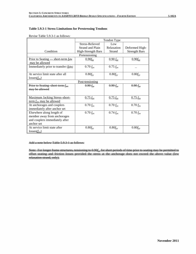
Table 5.9.3-1 Stress Limitations for Prestressing Tendons Revise Table 5.9.3-1 as follows:
Condition
Tendon Type Stress-Relieved Strand and Plain
High-Strength Bars
Low Relaxation
Strand Deformed High-
Strength Bars Pretensioning
Prior to Seating --- short-term fpbt may be allowed
0.90fpy 0.90 fpy 0.90fpy
Immediately prior to transfer (fpbt) 0.70 fpu 0.75 fpu ---
At service limit state after all losses(fpe)
0.80fpy 0.80fpy 0.80fpy
Post-tensioning Prior to Seating–short-term fpbt may be allowed
0.90 fpy 0.90 fpy 0.90 fpy
Maximum Jacking Stress–short-term fpbt may be allowed
0.75 fpu 0.75 fpu 0.75 fpu
At anchorages and couplers immediately after anchor set
0.70 fpu 0.70 fpu 0.70 fpu
Elsewhere along length of member away from anchorages and couplers immediately after anchor set
0.70 fpu 0.74 fpu 0.70 fpu
At service limit state after losses(fpe)
0.80fpy 0.80fpy 0.80fpy
Add a note below Table 5.9.3-1 as follows: Note: For longer frame structures, tensioning to 0.90fpy for short periods of time prior to seating may be permitted to offset seating and friction losses provided the stress at the anchorage does not exceed the above value (low relaxation strand, only).

SECTION 5: CONCRETE STRUCTURES CALIFORNIA AMENDMENTS TO AASHTO LRFD BRIDGE DESIGN SPECIFICATIONS – FOURTH EDITION 5-102B
November 2011
This page is intentionally left blank.

SECTION 5: CONCRETE STRUCTURES CALIFORNIA AMENDMENTS TO AASHTO LRFD BRIDGE DESIGN SPECIFICATIONS – FOURTH EDITION 5-107A
November 2011
Table 5.9.4.2.2-1 Tensile Stress Limits in Prestressed Concrete at Service Limit State After Losses, Fully Prestressed Components Revise Table as follows:
Bridge Type Location Stress Limit Segmental and Non-Segmental Bridges
Precompresssed Tensile Zone Bridges, Assuming Uncracked Sections—components with bonded prestressing tendons or reinforcement, subjected to permanent loads only.
No tension
Other Than Segmentally Constructed Bridges
Tension in the Precompressed Tensile Zone Bridges, Assuming Uncracked Sections
• For components with bonded prestressing tendons or reinforcement that are subjected to not worse than moderate corrosion conditions, and are located in Caltrans’ Environmental Areas I or II.
• For components with bonded prestressing tendons
or reinforcement that are subjected to severe corrosive conditions, and are located in Caltrans’ Environmental Area III.
• For components with unbonded prestressing
tendons.
cf '19.0 (ksi)
cf '0948.0 (ksi)
No tension
Segmentally Constructed Bridges
(no changes) (no changes)

SECTION 5: CONCRETE STRUCTURES CALIFORNIA AMENDMENTS TO AASHTO LRFD BRIDGE DESIGN SPECIFICATIONS – FOURTH EDITION 5-107B
November 2011
This page is intentionally left blank.

SECTION 5: CONCRETE STRUCTURES CALIFORNIA AMENDMENTS TO AASHTO LRFD BRIDGE DESIGN SPECIFICATIONS – FOURTH EDITION 5-111A
November 2011
C5.9.5.2.2b
Add a new last Paragraph:
For tendon lengths greater than 1200 feet, investigation is warranted on current field data of similar length frame bridges for appropriate values of µ.
Revise as follows: Table 5.9.5.2.2b-1 Friction Coefficients for Post-Tensioning Tendons
Type of Steel Type of Duct K /ft μ Wire or strand Rigid and semi-rigid
galvanized metal sheathing
0.0002 0.15-0.25
Tendon Length: < 600 ft 0.0002 0.15 600 ft < 900 ft 0.0002 0.20 900 ft < 1200 ft 0.0002 0.25 > 1200 ft 0.0002 >0.25 Polyethylene 0.0002 0.23 Rigid steel pipe deviators for external tendons
0.0002 0.25
High-strength bars
Galvanized metal sheathing
0.0002 0.30

SECTION 5: CONCRETE STRUCTURES CALIFORNIA AMENDMENTS TO AASHTO LRFD BRIDGE DESIGN SPECIFICATIONS – FOURTH EDITION 5-111B
November 2011
This page is intentionally left blank.

SECTION 5: CONCRETE STRUCTURES CALIFORNIA AMENDMENTS TO AASHTO LRFD BRIDGE DESIGN SPECIFICATIONS – FOURTH EDITION 5-113A
November 2011
5.9.5.2.3b Post-Tensioned Members Delete Eq. 5.9.5.2.3b-1 and replace with the following:
cgpci
ppES f
EE
NNf2
1−=∆
cgpci
ppES f
EE
f 50.0=∆
C5.9.5.2.3b Delete Eq. C5.9.5.2.3b-1 and replace with the following:
( )( )
p
cigggmgps
ggmgmgpbtpspES
EEIA
AeIA
AMeAeIfAN
Nf++
−+−=∆
2
2
21
( )
( )p
cigggmgps
ggmgmgpbtpspES
EEIA
AeIA
AMeAeIfAf
++
−+=∆
2
2
50.0

SECTION 5: CONCRETE STRUCTURES CALIFORNIA AMENDMENTS TO AASHTO LRFD BRIDGE DESIGN SPECIFICATIONS – FOURTH EDITION 5-114A
November 2011
5.9.5.3 Approximate Estimate of Time-Dependent Losses
Add a new last paragraph:
For cast-in-place post-tensioned box girder bridges, the approximate estimate of time-dependent losses may be taken as a lump sum value of 20 ksi.
C5.9.5.3
Add a new last paragraph:
The expressions for estimating time-dependent losses in Table 5.9.5.3-1 were developed for pretensioned members and should not be used for post-tensioned structures. Research performed by the University of CA, San Diego (SSRP-11/02) indicates time-dependent losses for cast-in-place post-tensioned box girder bridges are lower than previously expected. A parametric study using equations presented in the aforementioned research indicates losses may range from 11 ksi to 21 ksi. The variance is due to several parameters, such as relative humidity, area of non-prestressing steel and strength of concrete.

SECTION 5: CONCRETE STRUCTURES CALIFORNIA AMENDMENTS TO AASHTO LRFD BRIDGE DESIGN SPECIFICATIONS – FOURTH EDITION 5-116A
November 2011
Table 5.9.5.3-1 Time-Dependent Losses in ksi. Revise Table as follows:
Type of Beam Section
Level
For Wires and Strands with fpu = 235, 250 or 270 ksi
For Bars with fpu = 145 or 160 ksi
Rectangular Beams, Solid Slab
Upper Bound Average
29.0 + 4.0 PPR 26.0 + 4.0 PPR
19.0 + 6.0 PPR
Pretensioned Box Girder Upper Bound Average
21.0 + 4.0 PPR 19.0 + 4.0 PPR
15.0
Single T, Double T, Hollow Core and Voided Slab
Upper Bound Average
6.039.0 1.0 - 0.15 6.06.0
cf + PPR′ −
6.033.0 1.0 - 0.15 6.06.0
cf + PPR′ −
6.031.0 1.0 0.15 6.0
6.0cf PPR′ − − +

SECTION 5: CONCRETE STRUCTURES CALIFORNIA AMENDMENTS TO AASHTO LRFD BRIDGE DESIGN SPECIFICATIONS – FOURTH EDITION 5-116B
November 2011
This page is intentionally left blank.

SECTION 5: CONCRETE STRUCTURES CALIFORNIA AMENDMENTS TO AASHTO LRFD BRIDGE DESIGN SPECIFICATIONS – FOURTH EDITION 5-120A
November 2011
5.9.5.4.3b Creep of Girder Concrete Revise equation 5.9.5.4.3b-1 as follows:
( ) ( )[ ] ( ) dfdfbcdc
pdfidbifbcgp
ci
ppCD Kttf
EE
KttttfEE
f ,,, ψψψ ∆+−=∆
( ) ( )[ ] ( ) dfdfbcdc
pdfidbifbcgp
ci
ppCD Kttf
EE
KttttfEE
f ,,, ψψψ ∆+−=∆

SECTION 5: CONCRETE STRUCTURES CALIFORNIA AMENDMENTS TO AASHTO LRFD BRIDGE DESIGN SPECIFICATIONS – FOURTH EDITION 5-120B
November 2011
This page is intentionally left blank.

SECTION 5: CONCRETE STRUCTURES CALIFORNIA AMENDMENTS TO AASHTO LRFD BRIDGE DESIGN SPECIFICATIONS – FOURTH EDITION 5-127A
November 2011
5.10.4.3 Effects of Curved Tendons Revise as follows:
Reinforcement shall be used to confine curved
tendons if required by Article 5.8.1.5. The reinforcement shall be proportioned to ensure that the steel stress at service limit state does not exceed 0.6 f y , and the assumed value of f y shall not exceed 60.0 ksi. Unless a strut-and-tie analysis is done and indicates otherwise, sSpacing of the confinement reinforcement shall not exceed either 3.0 times the outside diameter of the duct or 24.0 in.
Where tendons are located in curved webs or flanges or are curved around and close to re-entrant corners or internal voids, additional concrete cover and/or confinement reinforcement shall be provided. The distance between a re-entrant corner or void and the near edge of the duct shall not be less than 1.5 duct diameters.
When a tendon curves in two planes, the in plane and out of plane forces shall be added together vectorially.
Tendons shall not be bundled in groups greater than three when girders are curved in horizontal plane. Revise 5.10.4.3.1 as follows:
5.10.4.3.1 Design for In-Plane Force Effects 5.10.4.3.1a In-Plane Force Effects In-plane deviation force effects due to the change
in direction of tendons shall be taken as:
RpF u
inu− (5.10.4.3.1a-1)
where:
inuF − = the in-plane deviation force effect per unit
length of tendon (kip/ft)
uP = the tendon force factored as specified in Article 3.4.3 (kip)
R = the radius of curvature of the tendon at the
considered location (ft) The maximum deviation force shall be determined
on the basis that all tendons, including provisional tendons, are stressed. The provisions of Article 5.10.9 shall apply to design for in-plane force effects due to tendons curved at the tendon anchorage.
C5.10.4.3
Revise as follows:
Curved tendons induce deviation forces that are radial to the tendon in the plane of tendon curvature. Curved tendons with multiple strands or wires also induce out-of- plane forces that are perpendicular to the plane of tendon curvature.
In-plane force effects are due to a change in direction of the tendon within the plane of curvature. Resistance to in-plane forces in curved girder may be provided by increasing the concrete cover over the duct, by adding confinement tie reinforcement or by a combination thereof. Figure C5.10.4.3.1a-1 shows an in-plane deviation in the vertical curve, and Figure C5.10.4.3.1a-2 shows a potential in-plane deviation in the horizontal curve.
It is not the purpose of this article to encourage the use of curved tendons around re-entrant corners or voids. Where possible, this type of detail should be avoided.
Out-of-plane force effects are due to the spreading of the wires or strands within the duct. Out-of-plane force effects are shown in Figure C5.10.4.3.2-1 and can be affected by ducts stacked vertically or stacked with a horizontal offset.
C5.10.4.3.1 C5.10.4.3.1a In-plane forces occur, for example, in anchorage
blisters or curved webs, as shown in Figures C5.10.4.3.1a-1 and C5.10.4.3.1a-2. Without adequate reinforcement, the tendon deviation forces may rip through the concrete cover on the inside of the tendon curve, or unbalanced compressive forces may push off the concrete on the outside of the curve. Small radial tensile stresses may be resisted by concrete in tension.
The load factor of 1.2 taken from Article 3.4.3 and applied to the maximum tendon jacking force results in a design load of about 96 percent of the nominal ultimate strength of the tendon. This number compares well with the maximum attainable jacking force, which is limited by the anchor efficiency factor.

SECTION 5: CONCRETE STRUCTURES CALIFORNIA AMENDMENTS TO AASHTO LRFD BRIDGE DESIGN SPECIFICATIONS – FOURTH EDITION 5-128A
November 2011
The shear resistance of the concrete cover against pull out by deviation forces, Vr shall be taken as:
nr VV φ= (5.10.4.3.1-2) In which:
'125.0 cicr fdV = (5.10.4.3.1-3) where:
nV = nominal shear resistance of two shear planes per unit length (kips/in.)
φ = resistance factor for shear specified in Article 5.5.4.2
ed = minimum concrete cover over the tendon duct, plus one half of the duct diameter (in.)
'ei
f = specified compressive strength of concrete at time of initial loading or prestressing (ksi)
If the factored in plane deviation force exceeds the
factored shear resistance of the concrete cover, as specified in Eq. 5.10.4.3.1-2, fully anchored tie backs to resist the in plane deviation forces shall be provided in the form of either nonprestressed or prestressed reinforcement.
Where stacked ducts are used in curved girders, the moment resistance of the concrete cover, acting in flexure, shall be investigated.
For curved girders, the global flexural effect of out-of-plane forces shall be investigated.
Figure C5.10.4.3.1a-1- In-Plane Forces in a Soffit Blister
The radial component from the longitudinal web
stress in the concrete due to the compression in the cylindrical web must be subtracted.
The two shear planes for which Eq. 5.10.4.3.1.-3 gives Vn are as indicated Figure C5.10.4.3.1.-2 for single and multiple tendons.
Figure C5.10.4.3.1-2 In Plane Force Effects in
Curved Girders Due to Horizontally Curved Tendons Figure C5.10.4.3.1a-2 In Plane Force Effects in
Curved Girders Due to Horizontally Curved Tendons

SECTION 5: CONCRETE STRUCTURES CALIFORNIA AMENDMENTS TO AASHTO LRFD BRIDGE DESIGN SPECIFICATIONS – FOURTH EDITION 5-129A
November 2011
Where curved ducts for tendons other than those crossing at approximately 90 degrees are located so that the direction of the radial force from one tendon is toward another, confinement of the ducts shall be provided by: • Spacing the ducts to ensure adequate nominal
shear resistance, as specified in Eq. 5.1.4.3.1-2; • Providing confinement reinforcement to resist
the radial force; or • Specifying that each inner duct be grouted before
the adjacent outer duct is stressed.

SECTION 5: CONCRETE STRUCTURES CALIFORNIA AMENDMENTS TO AASHTO LRFD BRIDGE DESIGN SPECIFICATIONS – FOURTH EDITION 5-129B
November 2011
5.10.4.3.1b-Shear Resistance to Pull-out
The shear resistance per unit length of concrete cover against pull-out by deviation forces, Vr shall be taken as:
nr VV φ= (5.10.4.3.1b-1)
In which:
cieffn fdV '15.0= (5.10.4.3.1b-2)
where:
nV = nominal shear resistance of two shear planes
per unit length (kip/in.) φ = resistance factor for shear, 0.75.
effd = One-half the effective length of the failure plane
in shear and tension for a curved element (in.)
For single duct stack or for Sduct, ≤ dduct, deff shown in Detail (a) in Figure 5.10.4.3b-1, shall be taken as:
4duct
ceffddd += (5.10.4.3.1b-3)
For Sduct, ≥ dduct, deff shall be taken as the lesser of the following based on Paths 1 and 2 shown in Detail (b) in Figure 5.10.4.3.1b-1:
2duct
weffdtd += (5.10.4.3.1b-4)
24∑++= ductduct
ceff
sddd (5.10.4.3.1b-5)
where:
ducts = clear distance between tendon ducts in vertical
direction (in.)
ductd = outside diameter of prestress duct (in.)
cd = cover on duct (in.)
wt = web thickness (in.)
C5.10.4.3.1b
The two shear planes for which Eq. 5.10.4.3.1b-3 gives are as indicated in Figure 5.10.4.3.1b-1 for single and multiple tendons.
When a staggered of side-by-side group of ducts is located side by side in a single web, all possible shear and tension failure planes should be considered in determining deff.
A generic stirrup and duct tie detail is shown in Figure C5.10.4.3.1b-1. Small diameter reinforcing bars should be used for better development of these bars. There have been no reported web failures when this detail has been used.
Figure C5.10.4.3.1b-1 –Typical Stirrup and Duct Tie Detail

SECTION 5: CONCRETE STRUCTURES CALIFORNIA AMENDMENTS TO AASHTO LRFD BRIDGE DESIGN SPECIFICATIONS – FOURTH EDITION 5-129C
November 2011
Figure 5.10.4.3.1b-1 –Definition of deff If the factored in-plane deviation force exceeds
the factored shear resistance of the concrete cover, as specified in Eq. 5.10.4.3.1b-2, fully anchored stirrup and duct ties hooked around the outermost stirrup legs to resist the in-plane deviation forces shall be provided in the form of either nonprestressed or prestressed reinforcement. 5.10.4.3.1c-Cracking of Cover Concrete
Where the clear distance between ducts oriented in a vertical column is less than 1.5 in. the ducts shall be considered stacked. Resistance to cracking shall be investigated at the ends and midheight of the unreinforced cover concrete. The applied local moment per unit length at the ends of the cover shall be taken as:
C5.10.4.3.1c
Figure C5.10.4.3.1c-1 illustrates the concept of an
unreinforced cover concrete beam to be investigated for cracking. Experience has shown that a vertical stack of more than three ducts can result in cracking of the cover concrete. When more than three ducts are required, it is recommended that at least 1.5 in. spacing be provided between the upper and lower ducts of the two shacks.
The resistance factor is based on successful performance of curved post-tensioned box girder bridges in California.

SECTION 5: CONCRETE STRUCTURES CALIFORNIA AMENDMENTS TO AASHTO LRFD BRIDGE DESIGN SPECIFICATIONS – FOURTH EDITION 5-129D
November 2011
12
2ds
ds
inu
end
hhF
M
=
∑ −
(5.10.4.3.1c-1)
and the applied local moment per unit length at the midheight of the cover shall be taken as:
24
2ds
ds
inu
mid
hhF
M
=
∑ −
(5.10.4.3.1c-2)
where:
=dsh the height of the duct stack as shown in Figure
C5.10.4.3.1c-1
Tensile stresses in the unreinforced concrete cover resulting from Eqs. 5.10.4.3.1c-1 and 5.10.4.3.1c-2 shall be combined with the tensile stresses from regional bending of the web as defined in Article 5.10.4.3.1d to evaluate the potential for cracking of the cover concrete. If combined tensile stresses exceed the cracking stresses given by Eq. 5.10.4.3.1c-4, duct shall be restrained by stirrup and duct tie reinforcement.
rcr ff φ= (5.10.4.3.1c-3)
where:
85.0=φ (5.10.4.3.1c-4)
Figure C5.10.4.3.1c-1 –Hypothetical Unreinforced Concrete Cover Beam

SECTION 5: CONCRETE STRUCTURES CALIFORNIA AMENDMENTS TO AASHTO LRFD BRIDGE DESIGN SPECIFICATIONS – FOURTH EDITION 5-129E
November 2011
5.10.4.3.1d-Regional Bending:
The regional flexural effects of in-plane forces shall be taken as:
4÷= ∑ − cinuu hFM φ (5.10.4.3.1d-1)
where:
=contφ 0.6 continuity factor for interior web; 0.7
continuity factor for exterior webs
=ch span of the web between the top and bottom
slabs measured along the axis of the web
For curved girders, the local flexural and shear effect of out-of-plane forces as described in Article 5.10.4.3.2 shall be evaluated.
Where curved ducts for tendons other than those crossing at approximately 90 degrees are located so that the direction of the redial force from one tendon is toward another, confinement of the ducts shall be provided by: • Spacing the ducts to ensure adequate nominal
shear resistance, as specified in Eq. 5.10.4.3.1b-1; or.
• Providing confinement reinforcement to resist the radial force.
5.10.4.3.2
Revise the 2nd paragraph as follows:
If the factored shear resistance given by Eq. 5.10.4.3.1-2 5.10.4.3.1b-1 is not adequate, local confining reinforcement shall be provided throughout the curved tendon segments to resist all of the out-of-plane forces, preferably in the form of spiral reinforcement.
C5.10.4.3.1d
When determining tensile stresses for the purpose of evaluating the potential for cracking of the cover concrete as specified in Article 5.10.4.3.1c, the effect of regional bending is combined with bending of the local concrete cover beam. It is recommended that the effect of stirrups in resisting bending be ignored, and that the ducts be considered as voids in the transverse section of the web.
The wedging acting of strands within the duct due to vertical curvature of the tendon can exacerbate tendon pull out resulting from horizontal curvature of the tendon as described in Articles 5.10.4.3.1b and 5.10.4.3.1c.
C5.10.4.3.2
Add the following to the end of the paragraph: In horizontally curved bridges, out-of-plane forces due to the vertical curvature of tendons should be added to in-plane forces resulting from horizontal curvature of the tendons.

SECTION 5: CONCRETE STRUCTURES CALIFORNIA AMENDMENTS TO AASHTO LRFD BRIDGE DESIGN SPECIFICATIONS – FOURTH EDITION 5-130A
November 2011
5.10.5 External Tendon Supports Add the following to the end of the paragraph: External tendon supports in curved concrete box girders shall be located far enough away from the web to prevent the free length of tendon from bearing on the web at locations away from the supports. When deviation saddles are required for this purpose, they shall be designed in accordance with Article 5.10.9.3.7.
C5.10.5 Add the following:
Deviation saddles in tightly curved bridges may be considered as continuous across the soffit as recommended by Beaupre et. al. (1988)

SECTION 5: CONCRETE STRUCTURES CALIFORNIA AMENDMENTS TO AASHTO LRFD BRIDGE DESIGN SPECIFICATIONS – FOURTH EDITION 5-144A
November 2011
5.10.9.3.7 Deviation Saddles Add the following to the end of the paragraph: A load factor of 1.7 shall be used with the maximum deviation force. If using a method based on test results, resistance factors of 0.90 shall be used for direct tension and 0.85 shall be used for shear.
C5.10.9.3.7 Revise the last sentence as follows: Design and detailing guidelines are presented in Beaupre et. al. (1988) should result in safe and serviceable design.

SECTION 5: CONCRETE STRUCTURES CALIFORNIA AMENDMENTS TO AASHTO LRFD BRIDGE DESIGN SPECIFICATIONS – FOURTH EDITION 5-144B
November 2011
This page is intentionally left blank.

SECTION 5: CONCRETE STRUCTURES CALIFORNIA AMENDMENTS TO AASHTO LRFD BRIDGE DESIGN SPECIFICATIONS – FOURTH EDITION 5-182A
November 2011
5.11.4.3 Partially Debonded Strands
Revise the 2nd and 3rd Paragraphs as follows:
The number of partially debonded strands should shall not exceed 25 33 percent of the total number of strands.
The number of debonded strands in any horizontal row shall not exceed 40 50 percent of the strands in that row.

SECTION 5: CONCRETE STRUCTURES CALIFORNIA AMENDMENTS TO AASHTO LRFD BRIDGE DESIGN SPECIFICATIONS – FOURTH EDITION 5-182B
November 2011
This page is intentionally left blank.

SECTION 5: CONCRETE STRUCTURES CALIFORNIA AMENDMENTS TO AASHTO LRFD BRIDGE DESIGN SPECIFICATIONS – FOURTH EDITION 5-188A
November 2011
5.12.3 Concrete Cover Delete the existing text and table, and replace with the following:
The minimum concrete cover for protection of reinforcement against corrosion due to chlorides shall be as provided in Table 5.12.3-1.
"Corrosive" water or soil contains more than 500 parts per million (ppm) of chlorides. Sites that are considered corrosive due solely to sulfate content greater than 2,000 ppm and/or a pH of less than 5.5 shall be considered non-corrosive in determining minimum cover from Table 5.12.3-1, but shall conform to the requirements of Article 5.12.5.
Marine atmosphere includes both the atmosphere over land within 1,000 feet of ocean or tidal water, and the atmosphere above the splash zone. Tidal water, from corrosion considerations, is any body of water having a chloride content greater than or equal to 500 ppm. The splash zone is defined as the region from the Mean Lower Low Water (MLLW) elevation to 20 feet above the Mean Higher High Water (MHHW) elevation and/or a horizontal distance of 20 ft. from the edge of water. The concrete cover in structural elements that are in direct contact with ocean spray shall be based on the requirements for a chloride concentration greater than 10,000 ppm in the corrosive splash zone.
C5.12.3
Delete the existing text, and replace with the following:
The table for minimum concrete cover for protection against corrosion has been developed for a 75-year design life. However, the service life of bridge decks and barrier rails are typically less than 75 years. Therefore, the concrete mix design and cover requirements for corrosion protection of decks and barrier rails have incorporated these aspects.
Environmental conditions such as proximity to corrosive atmosphere, marine environment, wave action, water table elevation and chloride content have been incorporated in determining the cover requirements.
Corrosion protection can be improved by increasing concrete denseness or imperviousness to water, as well as by furnishing other protection methods. Such methods include:
a) a reduction in water-to-cementitious material ratio;
b) incorporating mineral admixtures/ supplementary cementitious materials into concrete mix design.
c) use of different kinds of epoxy-coated reinforcing bars (ECR);
d) protective concrete coatings; e) use of chemical admixtures; f) cathodic protection, and, g) use of alternate materials. The minimum concrete cover, concrete mix and
epoxy-coated reinforcement requirements for structural elements exposed to deicing salt, snow run-off or snow blower spray shall be adopted only if the Engineer determines that the structural elements are directly exposed to these corrosive conditions. For example, when the deck is subjected to deicing salt, snow run-off or snow blower spray, it is unlikely that the girders or bent cap will be exposed to the same harsh condition, particularly when there are no deck joints. Therefore, the girders and the bent cap may be designed for a non-corrosive exposure condition.
If other considerations, such as a need to reduce the dead load of a structure, require a further reduction in concrete cover than those specified in Table 5.12.3-1, then a reduction in cover should only be done after a thorough investigation and research into existing state-of-practice.

SECTION 5: CONCRETE STRUCTURES CALIFORNIA AMENDMENTS TO AASHTO LRFD BRIDGE DESIGN SPECIFICATIONS – FOURTH EDITION 5-188B
November 2011
This page is intentionally left blank.

SECTION 5: CONCRETE STRUCTURES CALIFORNIA AMENDMENTS TO AASHTO LRFD BRIDGE DESIGN SPECIFICATIONS – FOURTH EDITION 5-189A
November 2011
Table 5.12.3-1 Cover for Unprotected main Reinforcing Steel (in.). Delete Table 5.12.3-1 and replace with the following:
Table 5.12.3-1 Minimum Concrete Cover (inches) for 75 –year Design Life Exposure condition
Non-corrosive
Atmosphere/ soil/ water
Marine Atmospher
e
Corrosive soil above MLLW level
Corrosive soil below
MLLW level
(a)
Corrosive water
permanently below
MLLW level
(a), (b)
Corrosive splash zone Deicing salt, snow
run-off, or snow blower spray (a),
(c),(e)
Chloride Concentration (ppm) Chloride concentration (ppm) 500-5,000
(a)
5,001-10,000
(a)
Greater than
10,000
(a)
500-5,000
(a),(b)
5,001-10,000
(a),(b)
Greater than
10,000
(a),(b)
Footings & pile caps 3 3 3 4 5 3 2 2 3 3.5 2.5
Walls, columns & cast-in-place piles
2 3 3 4 5 3 2 2 3 3.5 2.5
Precast piles and pile extensions
2 2(d) 2(d) 2(b),(d) 3(b),(d) 2(d) 2 2 2(d) 2.5(d) 2(d)
Top surface of deck slabs
2 2.5 2.5 2.5 2.5(d) 2.5
Bottom surface of deck slab(g)
1.5 1.5 2 2.5 2.5(d) 2.5
Bottom slab of box girders
1.5 1.5 2 2.5 2.5(d) 1.5
Cast-in-place “I” and “T” girders; exposed faces of box-girder webs, bent caps, diaphragms, and hinged joints (f)
1.5 3 2 2.5 2.5(d) 3
Curbs & railings 1 1(b) 1 1 1(d) 1
Concrete surface not exposed to weather, soil or water
Principal reinforcement; 1.5 inches
Stirrups, ties and spirals: 1.0 inch
General Notes: 1. Mineral admixtures / supplementary cementitious materials are required for all exposure conditions, except for ‘non-corrosive’ exposure
conditions. 2. For protection of bundled bars, prestressing steel and /or ducts, see Articles 5.12.3-1, 5.12.3-2 and 5.12.3-3. 3. The minimum cover at the corners, beveled edges, and curved surfaces shall be the same as that in the corresponding structural elements.
Footnotes: (a) The maximum water to cementitious material ratio shall not exceed 0.40. (b) Use pre-fabricated epoxy coated reinforcing bars (ECR). (c) Use post-fabricated ECR. (d) Mineral admixtures / supplementary cementitious materials, in addition to those required by General Notes (1), may be required. (e) The minimum concrete cover and other requirements in structural elements exposed to de-icing salt, snow run-off, or snow blower spray
shall be adopted only where the structural elements are directly exposed to these corrosive conditions, otherwise the requirements specified for non-corrosive conditions shall be adopted.
(f) For precast “I” and “T” girders, the minimum cover may be reduced (depending on site conditions). (g) Permanent support bars placed in the bottom of the deck slab may have a cover that is ½ inch less than that shown in the table.

SECTION 5: CONCRETE STRUCTURES CALIFORNIA AMENDMENTS TO AASHTO LRFD BRIDGE DESIGN SPECIFICATIONS – FOURTH EDITION 5-189B
November 2011
5.12.3.1 Protection for Bundled Bars For bundled bars, the minimum concrete cover in
non-corrosive atmosphere shall be equal to the equivalent diameter of the bundle, but need not be greater than 2 inches; except for concrete cast against and permanently exposed to non-corrosive soil, where the minimum cover shall be 3 inches. In corrosive environment, the cover shall be the same as that specified in Table 5.12.3-1, except that it shall not be less than the cover specified for bundled bars in non-corrosive environment.
5.12.3.2 Protection for Prestressing Tendons
In corrosive environments, the minimum concrete
cover to prestressing steel not placed within ducts, shall be the same as that specified for reinforcement (Table 5.12.3-1), except that when epoxy-coated reinforcement is required per Table 5.12.3-1, the prestressing steel shall either be epoxy-coated or the minimum concrete cover to the prestressing steel shall be increased by 1.0 inch beyond that specified in Table 5.12.3-1.
Ducts for internal post-tensioned tendons, designed to provide bonded resistance, shall be grouted after stressing.
Other tendons shall be permanently protected against corrosion and the details of protection shall be indicated in the contract documents.
C5.12.3.2
In certain cases, such as the tieing together of
longitudinal precast elements by transverse post-tensioning, the integrity of the structure does not depend on the bonded resistance of the tendons, but rather on the confinement provided by the prestressing elements. The unbonded tendons can be more readily inspected and replaced, one at a time, if so required.
External tendons have been successfully protected by cement grout in polyethylene or metal tubing. Tendons have also been protected by heavy grease or other anticorrosion medium where future replacement is envisioned. Tendon anchorage regions should be protected by encapsulation or other effective means. This is critical in unbonded tendons because any failure of the anchorage can release the entire tendon.
5.12.3.3 Protection for Ducts
The minimum concrete cover for protection of ducts in corrosive environment shall be the same as that specified for reinforcement in Table 5.12.3-1, except that:
(a) the concrete cover over the duct shall not be less than one-half the diameter of the duct; and,
(b) when epoxy-coated reinforcement is required, the minimum concrete cover over the duct shall be increased by 0.50 inches beyond that specified for reinforcement in Table 5.12.3-1, but shall not be less than that specified in (a).

SECTION 5: CONCRETE STRUCTURES CALIFORNIA AMENDMENTS TO AASHTO LRFD BRIDGE DESIGN SPECIFICATIONS – FOURTH EDITION 5-189C
November 2011
5.12.4 Protective Coatings
Delete and replace with the following:
5.12.4 Protection of Exposed Metals
Exposed reinforcement, inserts and plates that are either attached to concrete or will be bonding with concrete, as well as other ferrous hardware, attachments and installations shall be properly protected from corrosion in accordance with the requirements of Table 5.12.3-1. Hot-dip galvanizing or an equivalent protective method may also be used. Appropriate reductions in requirements are permitted depending on the exposure conditions and/or duration.
5.12.5 Protection for Prestressing Tendons
Delete and replace with the following:
5.12.5 Protection of Concrete Exposed to Acids and Sulfate
The durability of concrete may be adversely affected by contact with acids and sulfates present in soil or water. When concrete is exposed to an acidic and/or a sulfate environment, then a special concrete mix design is required.

SECTION 5: CONCRETE STRUCTURES CALIFORNIA AMENDMENTS TO AASHTO LRFD BRIDGE DESIGN SPECIFICATIONS – FOURTH EDITION 5-190A
November 2011
5.13.2.2 Diaphragms Revise the 2nd and 3rd paragraphs as follows:
Intermediate diaphragms may be used between beams in curved systems or where necessary to provide torsional resistance and to support the deck at points of discontinuity or at right angle points of discontinuity or at angle points in girders.
For spread box beams and for curved box girders having an inside radius less than 800 ft, intermediate diaphragms shall be used.
C5.13.2.2 Add the following to the end of the 3rd Paragraph:
Some references have found that interior diaphragms contributed very little to the global behavior of concrete box girder bridges.

SECTION 5: CONCRETE STRUCTURES CALIFORNIA AMENDMENTS TO AASHTO LRFD BRIDGE DESIGN SPECIFICATIONS – FOURTH EDITION 5-215A
November 2011
5.14.1.4.1 General Revise the 1st Paragraph as follows:
The provisions of this Article shall apply at the
service and strength limit states as applicable. Article 5.14.1.4 need not be applied to design of multi-span bridges composed of precast girders with continuity diaphragms at bent caps.
C5.14.1.4.1
Insert before 1st Paragraph as follows:
Article 5.14.1.4 provides design requirements mainly for multi-span bridges composed of precast girders made continuous with a drop cap bent system. The research to develop these requirements did not consider an inverted T-cap bent system. Caltrans provides a continuous diaphragm by threading dowels through the dapped end of the precast girders prior to pouring concrete between the girder ends. Shear stirrups extend up into the deck, with especially close stirrup spacing at the girder ends. Positive moment is presumed to be transferred into the bent cap. Currently, Caltrans is sponsoring a research study to study and develop connection details between the inverted T-cap bent and precast girders. The requirements of Article 5.14.1.4 may be used as the guidance for design of multi-span bridges composed of precast girders made continuous with the drop cap bent system.

SECTION 5: CONCRETE STRUCTURES CALIFORNIA AMENDMENTS TO AASHTO LRFD BRIDGE DESIGN SPECIFICATIONS – FOURTH EDITION 5-215B
November 2011
This page is intentionally left blank.

SECTION 5: CONCRETE STRUCTURES CALIFORNIA AMENDMENTS TO AASHTO LRFD BRIDGE DESIGN SPECIFICATIONS – FOURTH EDITION 5-254A
November 2011
Add the following references: Holombo, Jay et al, NCHRP Web-Only Document 149, LRFD Minimum Flexural Reinforcement Requirements, 2009. Podolny, J. W. and J.M. Muller, 1982. Construction and Design of Prestressed Concrete Segmental Bridges, Wiley, New York, NY.
Menn, C. 1990. Prestressed Concrete Bridges. Birkhauser Verlag, Basel, Switzerland.
Nutt, R. 2008. “Design Specifications and Commentary for Horizontally Curved Concrete Box-Girder Highway Bridges.” NCHRP Report 620. Transportation Research Board, Washington, D.C.
Van Landuyt, D.W. 1991. “The Effect of Duct Arrangement on Breakout of Internal Post-Tensioning Tendons in Horizontally Curved Concrete Box-Girder Webs”, Theses, University of Texas at Austin.

SECTION 5: CONCRETE STRUCTURES CALIFORNIA AMENDMENTS TO AASHTO LRFD BRIDGE DESIGN SPECIFICATIONS – FOURTH EDITION 5-254B
November 2011
This page is intentionally left blank.