ecotec plus 937 - free boiler · pdf fileinstallation and maintenance instructions ecotec plus...
TRANSCRIPT

For the heating engineer
Installation and maintenance instructions
GB; IE
ecoTEC plus 937
VUI

Contents
2 Installation and maintenance instructions ecoTEC plus 937 0020031552_06
Contents
1 Notes on the documentation ................................41.1 Documents also having validity ..............................41.2 Storing documents .....................................................41.3 Symbols used ...............................................................41.4 Validity of the manual ...............................................41.5 Identification plates ...................................................41.6 CE label .........................................................................41.7 Benchmark ...................................................................51.8 Gas Council Number ..................................................5
2 Unit description, data and dimensions .............52.1 General notes ..............................................................52.2 Technical data .............................................................62.3 Dimensions ................................................................... 72.4 Structure and functional elements ........................92.5 Functional description ............................................. 10
3 Safety ...........................................................................113.1 Safety and warning information .............................113.1.1 Classification of warnings ........................................113.1.2 Structure of warnings ...............................................113.2 Intended use ................................................................113.3 General safety instructions .....................................123.4 General requirements ...............................................133.4.1 Preliminary remarks .................................................133.4.2 Related documents ...................................................13
4 General requirements .............................................144.1 Scope of supply and accessories ...........................144.2 Installation location...................................................144.3 Gas supply ...................................................................154.4 Flue pipe.......................................................................154.4.1 100 mm standard flue duct .....................................154.4.2 Optional 125 mm flue pipe .......................................164.5 Flue termination ........................................................164.6 Air supply .....................................................................174.7 Electrical connection ................................................174.8 System requirements ...............................................184.8.1 Water circulation system .........................................184.8.2 Filling and preparation of the heating system ...184.8.3 Pressure relief valve .................................................194.8.4 Pressure gauge ..........................................................194.8.5 Heating circuit expansion vessel ...........................194.8.6 Shift load storage tank expansion vessel.......... 204.9 Details for the pumps ............................................. 204.9.1 Circulation pump ..................................................... 204.9.2 Shift load storage tank circulation pump .......... 204.10 System-Bypass ......................................................... 204.11 Venting ....................................................................... 204.12 Condensate siphon .................................................. 20
5 Sequence of operations during installation ....215.1 Transporting the appliance .....................................215.2 Required minimum gaps/assembly clearances 235.2.1 Selecting the location for the shift load
storage tank and combination boiler ..................235.3 Unpacking the equipment ......................................235.4 Using the installation template ............................ 245.5 Flue exit ...................................................................... 245.6 Installation of the flue gas system ...................... 245.7 Fitting the appliance hanging bracket ................255.8 Mounting the combination boiler .........................255.9 Removing the front case ........................................265.10 General instructions concerning the heating
system .........................................................................265.11 Gas connection ..........................................................265.12 Connecting the hot and cold water .....................275.13 Connecting piping between the stratified
storage tank and the combi-heater .................... 285.14 Connecting the heating supply and return
lines ..............................................................................295.15 Installing the condensate drain line.................... 305.16 Connecting the drain pipe to the pressure
relief valve ...................................................................315.17 Connecting the drain hose to the pressure
relief valve of the stratified storage tank ...........315.18 Connecting the exhaust gas system to the
combi-heater ...............................................................315.19 Electrical connection ...............................................325.19.1 General requirements ..............................................325.19.2 Establishing the electrical connection for the
stratified storage tank ............................................325.19.3 Establishing the power supply ..............................335.19.4 Connection diagrams ................................................................34
5.20 Control units ..............................................................375.20.1 Vaillant control units and accessories ................375.20.2 External electrical controllers ...............................375.20.3 Details for the connection of an external
timer to the terminal strip .....................................375.20.4 Optional plug-in timers by Vaillant ..................... 385.21 Thermostatic radiator valves ............................... 385.22 Frost prevention ...................................................... 385.23 Heating pump ........................................................... 385.24 Anti-cyclic "Economiser" control system .......... 385.25 Automatic pump spin control ............................... 38
6 Commissioning, Part I ...........................................396.1 Preparatory checks of the electrical system ....396.2 Gas supply ..................................................................396.3 Cold water supply .....................................................396.4 Filling and bleeding the heating system .............396.4.1 Checking the fill pressure in the heating
system .........................................................................396.4.2 Filling device for ecoTEC plus 937 ...................... 406.4.3 Filling the heating system for the first time ..... 40
Contents
3Installation and maintenance instructions ecoTEC plus 937 0020031552_06
6.5 Flushing the system for the first time ("cold") ..416.6 Filling the condensate drain trap ..........................416.7 Setting the pump output .........................................416.8 Adjusting the bypass ................................................416.9 Checking the gas setting ....................................... 426.9.1 Checking for tightness of the flue gas
installation and flue gas recirculation ................ 426.9.2 Checking the gas flow rate ....................................436.9.3 Checking the gas inlet working pressure ...........436.10 Assembling the front panel ................................... 446.11 Adjusting the central heating system (range
rating) ......................................................................... 446.12 Converting the gas type ........................................ 45
7 Commissioning Part II: Functional checks ... 457.1 Functional checks .................................................... 457.1.1 Method of procedure .............................................. 457.1.2 Heating ....................................................................... 457.1.3 Hot water operation ............................................... 467.1.4 Storage tank charging ............................................ 467.1.5 Conclusive flushing of the heating system
("hot") ..........................................................................477.2 Briefing users ............................................................477.3 Factory guarantee ................................................... 48
8 Inspection and maintenance .............................. 488.1 Inspection and maintenance intervals ............... 488.1.1 General inspection and maintenance
instructions ............................................................... 498.1.2 Safety instructions .................................................. 498.1.3 Checking the CO
2 concentration .......................... 50
8.1.4 Adjusting the CO2 concentration
(or the air ratio) .........................................................518.1.5 Inspection and maintenance work steps ............528.2 Maintaining the compact thermal module .........538.2.1 Removing the compact thermal module ............538.2.2 Cleaning the integral condensation heat
exchanger .................................................................. 548.2.3 Checking the burner ............................................... 548.2.4 Installing the compact thermal module ............. 548.3 Cleaning the condensate trap .............................. 558.4 Cleaning strainer in cold water supply .............. 568.5 Checking filling pressure of the expansion
vessel of the combination boiler ......................... 568.6 Checking filling pressure of the expansion
vessel of the shift load storage tank ...................578.7 Re-commissioning the combination boiler .........578.8 Test mode ...................................................................579.1 Logical fault finding procedure ............................ 589.1.1 Status codes ............................................................. 589.1.2 Diagnostic codes ...................................................... 599.1.3 Error codes .................................................................629.1.4 Fault memory ............................................................629.2 Test programmes .................................................... 659.3 Resetting the parameters to factory settings . 65
10 Replacing components ......................................... 6510.1 Safety instructions .................................................. 6510.2 Replacing the burner .............................................. 6610.3 Replacing the fan or the gas valve .................... 6610.4 Replacing the expansion vessel ............................6710.5 Replacing the primary heat exchanger ............. 6810.6 Replacing the expansion vessel of the shift
load storage tank ..................................................... 6910.7 Replacing the storage tank pump of the shift
load storage tank ..................................................... 6910.8 Replacing the aqua sensor .................................... 7010.9 Replacing the electronics on the shift load
storage tank ................................................................7110.10 Replacing the electronics and display on the
combi-heater ...............................................................71
11 Recycling and disposal .........................................72
12 Vaillant service ........................................................72
EC declaration of conformity ............................................73

4 Installation and maintenance instructions ecoTEC plus 937 0020031552_06
1 Notes on the documentation
The following information is intended to help you throughout the entire documentation. Further documents apply in combination with this instal-lation and maintenance manual.We accept no liability for any damage caused by failure to observe these instructions.
1.1 Documents also having validity
Always observe all installation instructions for struc-tural parts and components of the system when installing the ecoTEC plus 937. These installation instructions are enclosed with the various system components as well as additional components.Also observe all the operating instructions included with the system components.
1.2 Storing documents
Pass these installation instructions and all other applicable documents and, if necessary, any required aids to the system operator.
He will be responsible for storing them so that the instructions and aids are available when required.
1.3 Symbols used
The symbols used in the manual are explained below:
aSymbol denoting danger
imminent danger to lifeRisk of severe personal injuryRisk of slight personal injury
–––
eSymbol denoting danger
Risk of death from electric shock–
bSymbol denoting danger
Risk of material damageRisk of damage to the environment
––
iSymbol denoting additional useful tips and information
> Symbol for a required task
>
>
>
1.4 Validity of the manual
This installation manual applies exclusively to the unit with the following part number:
0010003809
The part number of the unit can be obtained from the identification plate. The 7th to 16th digits of the serial number form the article number.
1.5 Identification plates
The identification plate of the ecoTEC plus 937 is located on the underside of the unit.
1.6 CE label
CE labelling shows that the appliances comply with the basic requirements of the following directives:
Directive 2009/142/EEC of the Commission with revisions"Directive for Harmonisation of Legal Regulations of the Member States for Gas Consumer UNits" (Gas equipment directive)Directive 92/42/EEC of the Commission with revi-sions"Directive Concerning the Efficiency of New Hot Water Heating Boilers Fired by Liquid or Gaseous Fuels“ (Efficiency directive)Directive 2006/95/EEC of the Commission with revisions"Directive Concerning Electrical Operating Equipment for Use Within Specific Voltage Limits“ (Low voltage directive)Directive 2004/108/EEC of the Commission with revisions"Directive Concerning Electromagnetic Compatibility"
The units comply with the prototype described in the EU Prototype Test Approval:PIN-No. CE-0085BP0464The units comply with the following standards:
EN 483EN 625EN 677EN 50165EN 55014EN 60335-1EN 60529EN 61000-3-2EN 61000-3-3
–
–
–
–
–
–––––––––
1 Notes on the documentation

Installation and maintenance instructions ecoTEC plus 937 0020031552_06 5
1.7 Benchmark
i Vaillant Ltd. supports the Benchmark Initia-
tive. You will find the Benchmark Logbook on the last page of this instruction manual. It is very important that this document be filled out properly when installing, commissioning and handing-over to the owner of the installa-tion.
1.8 Gas Council Number
Appliance Gas council Number
ecoTEC plus 937 47-044-39
Table 1.1 Gas Council Number
2 Unit description, data and dimensions
2.1 General notes
The ecoTEC plus 937 is designed for use in a closed cen-tral heating system and is comprehensively tested in the factory. The ecoTEC plus 937 is supplied fitted with a circulation pump, an expansion vessel, a diverter valve and a 15 l layered storage tank. The shift load storage tank and combination boiler can be easily mounted on an internal wall and installed with a vertical or horizon-tal RSF (room sealed fan assisted flue).The combination boilers operate with a standard flue gas system (outside diameter 100 or 125 mm). To increase the flexibility of the system, extensions and additional right-angle and leg extensions are available. If required, an inhibitor can be used in the system. Instruc-tions for the use of these inhibitors can be found in their instructions.All combination boilers are equipped with an internal diagnostic system which provides information concern-ing the operating status of the combination boiler. This diagnostic system provides important information to support commissioning and troubleshooting.
Notes on the documentation 1Unit description, data and dimensions 2
6 Installation and maintenance instructions ecoTEC plus 937 0020031552_06
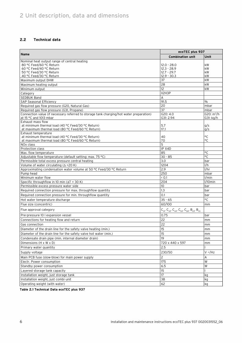
2.2 Technical data
NameecoTEC plus 937
Combination unit Unit
Nominal heat output range of central heating 80 °C Feed/60 °C Return 60 °C Feed/40 °C Return 50 °C Feed/30 °C Return 40 °C Feed/30 °C Return
12.0 - 28.012.3 - 28.912.7 - 29.712.9 - 30.3
kWkWkWkW
Maximum output DHW 37 kW
Maximum heating output 28 kWMinimum output 12 kWCategory II2H3PSEDBUK Band ASAP Seasonal Efficiency 91.5 %Required gas flow pressure (G20, Natural Gas) 20 mbarRequired gas flow pressure (G31, Propane) 37 mbarConnection value (if necessary referred to storage tank charging/hot water preparation) at 15 °C and 1013 mbar
G20: 4.0G31: 2.94
G20: m3/hG31: kg/h
Exhaust mass flow at minimum thermal load (40 °C Feed/30 °C Return) at maximum thermal load (80 °C Feed/60 °C Return)
5.717.1
g/sg/s
Exhaust temperature at minimum thermal load (40 °C Feed/30 °C Return) at maximum thermal load (80 °C Feed/60 °C Return)
4070
°C°C
NOx class 5Protection class IP X4DMax. flow temperature 85 °CAdjustable flow temperature (default setting: max. 75 °C) 30 - 85 °CPermissible total excess pressure central heating 3.0 barVolume of water circulating ( =20 K) 1204 l/hApproximating condensation water volume at 50 °C Feed/30 °C Return 2.9 l/hrPump head 250 mbarMinimum water flow < 0.1 l/minSpecific throughflow in 10 min (T = 30 K) 204 l/10minPermissible excess pressure water side 10 barRequired connection pressure for max. throughflow quantity 1.3 bar
Required connection pressure for min. throughflow quantity 0.1 bar
Hot water temperature discharge 35 - 65 °C
Flue size (concentric) 60/100 mm
Flue approval category C13, C
33, C
43, C
53, C
83, B
23, B
33
Pre-pressure 10 l expansion vessel 0.75 bar
Connections for heating flow and return 22 mm
Gas connection 22 mm
Diameter of the drain line for the safety valve heating (min.) 15 mm
Diameter of the drain line for the safety valve hot water (min.) 15 mm
Condensate drain pipe (min. internal diameter drain) 19 mm
Dimensions (H x W x D) 720 x 440 x 597 mm
Primary water quantity 2.5 l
Supply voltage 230/50 V ~/Hz
Main PCB fuse (slow-blow) for main power supply 2 AElectr. Power consumption 175 WStandby power consumption 6.5 W
Layered storage tank capacity 15 lInstallation weight, just storage tank 17 kgInstallation weight, just combi unit 38 kg
Operating weight (with water) 62 kg
Table 2.1 Technical Data ecoTEC plus 937
2 Unit description, data and dimensions
Installation and maintenance instructions ecoTEC plus 937 0020031552_06 7
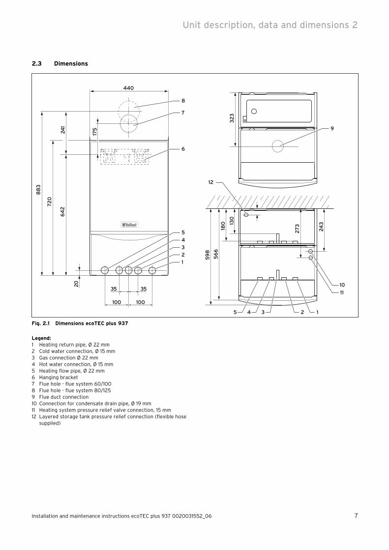
2.3 Dimensions24
1
20
64
2
720
88
3
32
3
100100
440
35 35
130
180
175
27
3
24
3
56
6
59
8
8
6
4
3
2
1
5
7
9
12345
10
11
12
Fig. 2.1 Dimensions ecoTEC plus 937
Legend:1 Heating return pipe, Ø 22 mm2 Cold water connection, Ø 15 mm 3 Gas connection Ø 22 mm4 Hot water connection, Ø 15 mm 5 Heating flow pipe, Ø 22 mm6 Hanging bracket7 Flue hole - flue system 60/1008 Flue hole - flue system 80/1259 Flue duct connection10 Connection for condensate drain pipe, Ø 19 mm11 Heating system pressure relief valve connection, 15 mm12 Layered storage tank pressure relief connection (flexible hose
supplied)
Unit description, data and dimensions 2

8 Installation and maintenance instructions ecoTEC plus 937 0020031552_06
241
20
64
2
720
88
3
100100
440
35 35
175
6
4
3
2
1
5
130180 198
12345
7
8
Fig. 2.2 Dimensions shift load storage tank
Legend:1 Heating return pipe, Ø 22 mm2 Cold water connection, Ø 15 mm 3 Gas connection Ø 22 mm4 Hot water connection, Ø 15 mm 5 Heating flow pipe, Ø 22 mm6 Hanging bracket7 Shift load storage tank pressure relief connection (flexible hose
supplied)8 Cover
2 Unit description, data and dimensions

Installation and maintenance instructions ecoTEC plus 937 0020031552_06 9
2.4 Structure and functional elements
The ecoTEC plus 937 consists of a modified combination boiler anda 15 litre shift load storage tank.
Mains cold water heated by the combi unit is fed to the heat insulated storage tank by means of a modulating storage tank charging pump. The combi unit supplies the shift load storage tank with electrical energy for the storage tank charging pump.
1
2
3
4
6
5
7
8
13
12
10
9
11
Fig. 2.3 Function elements combi unit
Legend:1 Expansion vessel combi boiler2 Air intake pipe3 Compact thermal module4 Ignition electrode5 Fan6 Diverter valve with built in automatic adjustable bypass7 pump8 Electronics box9 Hot water heat exchanger10 Gas valve11 Pressure sensor12 Heat exchanger13 Connection flue duct
––
1
2
3
4
5
Fig. 2.4 Function elements shift load storage tank
Legend:1 Shift load storage tank expansion vessel2 Aqua-Sensor3 Storage charging pump4 NTC temperature sensor - hot water outlet5 Storage tank pressure relief valve
Unit description, data and dimensions 2

10 Installation and maintenance instructions ecoTEC plus 937 0020031552_06
2.5 Functional description
1
2
3
4
14
13
12
6
7
8
9
11
10
1617
1520
19
18 5
c b
a
21
Fig. 2.5 Sequence diagram
Legend:1 Exhaust gas2 Heat exchanger3 Combustion chamber4 Condensate siphon5 Expansion vessel6 Operating display7 Secondary heat exchanger8 Automatic air vent9 Pump10 Pressure relief valve11 Diverter valve12 Gas valve13 Fan
14 Compact thermal module15 Shift load storage tank electronics16 storage charging pump17 Aqua-Sensor18 Stainless steel storage tank19 Storage tank insulation20 Expansion vessel21 opt. accessory 0020057235 for integrating a circulation pump
NTC sensors shift load storage tanka Storage tank sensorb Infeed sensor SWTc Storage tank charging sensor
2 Unit description, data and dimensions

Installation and maintenance instructions ecoTEC plus 937 0020031552_06 11
The ecoTEC plus 937 is a fully-automatic wall-mounted unit with condensing technology for central heating and hot water preparation and with a shift load storage tank for the storage of hot water.Mains cold water heated by the combi boiler is fed to the heat insulated storage tank by means of a modulat-ing storage tank charging pump.The provision of hot water takes place directly from the combi boiler without the need for a copper cylinder, a cold water tank or a supply and expansion vessel with the corresponding pipework. The provision of hot water has priority over the central heating.The combi unit supplies the shift load storage tank with electrical energy for the storage tank charging pump.The combi unit is equipped with a warm start function which keeps the heat exchanger hot so that hot water is immediately available.The temperature in the hot water heat exchanger is lim-ited by the control system.Fitting a water softener on the mains cold water inlet of the combi boiler is not necessary. In regions with extremely hard water (greater than 300 mg/l of CaCO
3)
however a water softener may still be fitted in order to prevent the formation of scale build up in the water pipes.The heating system can be filled using the filling devices fitted to the ecoTEC plus combination boilers.The ecoTEC plus 937 is be supplied for natural gas and can be converted for propane gas with a conversion kit.
3 Safety
3.1 Safety and warning information
When conducting installation and maintenance work, observe the general safety instructions and the warning notes that appear before each of the actions.
3.1.1 Classification of warnings
The following warning signs and signal words are used to classify the warning notices in accordance with the severity of the possible danger:
Warning signSignal word
Explanation
aDanger! Immediate danger to life or risk
of severe personal injury
eDanger! Risk of death from
electric shock
aWarning! Risk of slight personal injury
bCaution! Risk of material or environmental
damage
3.1.2 Structure of warnings
Warning signs are identified by an upper and lower sep-arating line. They are laid out according to the following basic principle:
a Signal word! Type and source of danger.Explanation of the type and source of danger.
Measures for averting the danger
3.2 Intended use
The ecoTEC plus 937 is a state-of-the-art appliance which has been constructed in accordance with recog-nised safety regulations. Nevertheless, there is still a risk of injury or death to the user or others or of dam-age to the equipment and other property in the event of improper use or use for which they are not intended.
>
Unit description, data and dimensions 2Safety 3

12 Installation and maintenance instructions ecoTEC plus 937 0020031552_06
The unit is not intended for use by persons (including children) with reduced physical, sensory or mental capa-bilities, or lack of experience and/or knowledge, unless they have been given supervision or instruction con-cerning use of the unit by a person responsible for their safety.Children must be watched to ensure that they do not play with the unit.The appliance is designed to generate heat for closed hot water central heating systems and for instantane-ous hot water supply.The use of the ecoTEC plus 937 in vehicles, such as mobile homes and caravans, is not classed as intended use. Units that are not classed as vehicles are those that are installed in a fixed and permanent location and that do not have any wheels (fixed installation).Any other use, or use beyond that specified, shall be considered improper use. Any direct commercial or industrial use is also deemed as improper. The manufac-turer/supplier is not liable for any damage resulting from improper use. The user alone bears this risk.Intended use includes the observance of the operating and installation manual and the adherence to the inspection and maintenance conditions.Any improper use is forbidden.
3.3 General safety instructions
European installation directiveInstallation and maintenance of the appliance should only be undertaken by a competent person approved atthe time by the Health and Safety executive and in accordance with the gas safety (installation and use)regulations 1998. The existing regulations, rules and guidelines must be observed when doing so. He is also responsible for inspection, maintenance and repairs to the unit, as well as alterations to the gas volume setting.Only IE: The installation must comply with the current Version of I.S.813 "Domestic Gas Installations" and the current Building Regulations.
The current ETCI Regulations for installing electrical equipment must also be observed.
What to do in an emergency if you smell gasA malfunction may mean that there is a smell of gas and it may lead to a risk of poisoning or explosion. If there is a smell of gas in the building, proceed as follows:
Avoid rooms that smell of gas.If possible, open doors and windows fully and ensure air is circulating.Avoid the use of naked flames (e.g. lighters, matches).Do not smoke.Do not use any electrical switches, plugs, doorbells, telephones or other communication systems in the building.Close the gas meter isolator device or the main isola-tor device.
>
>
>
>
>
>
>
If possible, close the gas stop cock on the unit.Warn other occupants in the building by knocking or calling.Leave the building.If you can actually hear gas leaking, leave the build-ing immediately and ensure that no third parties enter the building.Alert the police and fire brigade when you are outside the building.Use a telephone outside the building to inform the emergency service department of the gas supply company.
What to do in an emergency if you smell exhaust fumesA malfunction may mean that there is a smell of exhaust fumes and may lead to a risk of poisoning. If there is a smell of exhaust fumes in the building, proceed as fol-lows:
Open doors and windows fully and ensure air is circu-lating.Switch off the gas-fired wall-hung boiler.
Changes to the surroundings of the heating deviceChanges may not be made to the following equipment:
the heating appliancethe gas, water and power supply pipes/cablesthe exhaust gas delivery pipethe structural conditions that may influence the oper-ating safety of the appliance, especially supply air openings.
Personal injury and/or material damage caused by improper use and/or unsuitable toolsImproper use and/or unsuitable tools may result in dam-age (e.g. gas or water leaks).
Always use a suitable open-ended spanner to tighten or undo threaded connections. Do not use pipe wrenches, extensions, etc.
Important instructions for propane appliancesBleeding the liquid gas tank when installing the system:System:
Before installing the device, make sure that the gas tank has been bled.
The liquid gas supplier is responsible for ensuring that the tank is bled properly. If the tank is not bled properly, this may result in Ignition problems.
In such cases, first contact the person in charge of filling the tank.
Affixing the tank stickerAffix the enclosed tank sticker (propane quality) on the tank where it is clearly visible or on the bottle cabinet, as close to the filler nozzle as possible.
Avoid ignition and combustion noise as well as fault shutdowns caused by incorrect gas types.
Only use propane gas in accordance with DIN 51622.
>
>
>
>
>
>
>
>
––––
>
>
>
>
>
>
3 Safety

Installation and maintenance instructions ecoTEC plus 937 0020031552_06 13
Preliminary remarks for room sealed appliancesThis appliance should only be installed in conjunction with either a Vaillant flue system or an alternative approved system (details of flue approval categories can be found in the technical section of the installation manual).
Install the flue system as detailed in the separate flue installation instructions supplied with this boiler.
3.4 General requirements
3.4.1 Preliminary remarks
This appliance must only be installed and commissioned by a competent person approved at the time by the Health and Safety Executive. Please check with your installer that he is able to carry-out all the necessary works including official notification of the works to the relevant body upon completion.
3.4.2 Related documents
The installation of the appliance and any associated hot water system must be in accordance with (but not lim-ited to) the following; COSHH regulations, Gas Safety (Installation and Use) Regulations 1998, Health and Safety Document No. 635 (The Electricity at Work Regu-lations 1989), BS7671 (IEE Wiring Regulations) and the Water Supply (Water Fitting) Regulations 1999, or The Water Bylaws 2000 (Scotland). It should also be in accordance with the relevant requirements of the Local Authority, Building Regulations, The Building Regula-tions (Scotland), The Building Regulations (Northern Ire-land) and the relevant recommendations of the follow-ing British Standards: BS 6700: Services supplying water for domestic use within buildings and their curtilages.BS 6798: Specification for installation of gas fired boil-ers not exceeding 60 kW input.BS 6891: Specification for installation of low pressure gas pipework up to 28 mm (R1) in domestic premises (2nd family gas).BS 7593: Treatment of water in domestic hot water central heating systems.Institute of Gas Engineers Publication IGE/UP/7/1998: ”Guide for gas installations in timber framed housing”BS. 5482 Pt. 1 Domestic butane and propane gas burn-ing installations.IGE/UP1 Soundness testing and purging of industrial and commercial gas installation.IGE/UP2 Gas installation pipework, boosters and com-pressors on industrial and commercial premises.IGE/UP10 Installation of gas appliances in industrial and commercial premises.BS. 6644: Installation of gas fired hot water boilers of rated inputs between 60 kW and 2 MW (2nd and 3rd family gases).
>
BS. 5449: Forced circulation hot water central heating systems for domestic premises. Note: only up to 45 kW.BS. 6880: Low temperature hot water heating systems of output greater than 45 kW.Part 1 Fundamental and design considerations.Part 2 Selection of equipment.Part 3 Installation, commissioning and maintenance.BS. 4814: Specification for: Expansion vessels using an internal diaphragm, for sealed hot water heating sys-tems.BS. 5440: Installation and maintenance of flues and ventilation for gas appliances of rated input not exceed-ing 70 kW net (1st, 2nd and 3rd family gases).Part 1 Specification for installation of flues.Part 2 Specification for installation and maintenance
of ventilation for gas appliances.
Safety 3

14 Installation and maintenance instructions ecoTEC plus 937 0020031552_06
4 General requirements
4.1 Scope of supply and accessories
1 1
10
9
8
7
6 5
4
3
2
1
Fig. 4.1 Scope of supply and accessories
The shift load storage tank and the combi boiler are delivered pre-assembled in one packaging unit. Check that all parts have been delivered undamaged (see Fig. 4.1 and Table 4.1 ).
i At this stage do not yet remove the combi
boiler and the shift load storage tank from the expanded polystyrene base to prevent any damage.
Pos. Quantity Name
1 1 Combi boiler ecoTEC plus
2 1 Bottom cover ecoTEC plus
3 1 Installation template
4 4 Isolating valves and filling loop
5 6Connecting pipes (gas, heating, water, safety valve)
6 5
Adapter set, consisting of connecting pipes between the shift load storage tank and the combi boiler for gas, heating flow and return and water flow and return
7 2 Installation and connection accessories:
8 3User, installation and service, flue installation manuals
9 1 Bottom cover for shift load storage tank
10 1 Shift load storage tank
11 1 Hanging bracket
Table 4.1 Scope of supply and accessories
4.2 Installation location
When selecting the installation location observe the regulations and recommendations for combi boilers!
The installation location for the combi boiler and shift load storage tank must permit proper connection of the flue gas system to the combi boiler. In addition there must be sufficient space for maintenance work and air circulation around the combi boiler and the shift load storage tank.The Combi boiler and shift load storage tank can be mounted together in any room you wish to choose.In rooms with a bath or a shower, the special require-ments of BS 7671 (IEE Regulations), the electro-techni-cal stipulations of the Building Standards (Scotland) Regulations and, in IE, the current issue of IS 813 and the current ETCI Stipulations must especially be observed.
e Danger!Risk of electrocution when installing an appliance that depends on room air in a room with a bath or shower.If electric switches and controls are installed too close to a bath or shower, there is a risk of electric shock for the person using the facility.
Install electric switches and controls that are operated via mains voltage out of reach of the bath or shower.
In the event of installation in unusual locations, special provisions may have to be made. Detailed instructions for this can be found in BS 5546 and in BS 6798.The ecoTEC plus 937 must be mounted on a flat, verti-cal wall which is sufficiently strong to hold the weight of the shift load storage tank and the combi boiler.
>
>
4 General requirements

Installation and maintenance instructions ecoTEC plus 937 0020031552_06 15
It is possible to mount onto a wall made of flammable material if the regulations of the Local Authority and the legal building regulations are fulfilled. In this case however, the unit would have to be mounted in a spe-cially made enclosure. (You can also use an existing cabinet or existing enclosure as long as it can be modi-fied accordingly to suit the new application.) Further details concerning the fundamental characteristics when modifying existing cabinets or enclosures, including the requirements for ventilation, are described in BS 6798.
i If the boiler is to be installed in a half-tim-
bered house, the installation must be under-taken in accordance with the Institute of Gas Engineers Publication IG/UP/7 Edition 2 „Gas installations in timber framed and light steel framed buildings“.
i If the boiler is to be installed in an airing
cupboard it is not required to separate the boiler with a non-combustible partition. How-ever installation and servicing clearances must be maintained, and the appliance kept clear of any clothing.
Please note the following instructions before choos-ing where to install the boiler:
b Caution!Possible material damage due to an unsuit-able installation location.The appliance may be damaged by frost, aggressive vapours or dust.
Do not install the appliance in rooms that are susceptible to frost. Do not operate the appliance in rooms with aggressive vapours or dust unless it is operated in way that does not depend on the room air.
Make sure that, when selecting the installation location and when operating the unit, the combustion air is free from chemical substances which contain fluorine, chlo-rine, sulphur etc. Sprays, solvents and cleaning agents, paints, adhesives etc.can contain substances of this type which can cause corrosion in the flue gas system, in the worst case even if the unit is operated as an open vent appliance. Particularly in hairdressing salons, lacquering and finishing, cleaning facilities, the appliance must be operated independent of the ambient air! Otherwise, a separate installation room is required to guarantee that the combustion air supply is free from the afore men-tioned substances.
>
>
>
4.3 Gas supply
The gas provider must guarantee the availability of an adequate gas supply. The connection of a gas meter in the supply line is only permitted when carried out by the gas provider and a company appointed by him.If there is an existing gas meter you must check that it is suitable for the required gas flow rate.Installation pipes should be fitted in accordance with BS 6891. In IE in accordance with the current issue of IS 813. The pipework between the gas meter and the combi boiler must be of an appropriate size. Do not use any pipes that are smaller than the connection to the combi boiler (22 mm). The entire installation must be checked for leaks and purged in accordance with BS 6891.
4.4 Flue pipe
a Danger!Risk of personal injury and material dam-age as a result of malfunctions.Malfunctions may be caused by using acces-sories that are not specified in the Vaillant installation manual for air/exhaust ducts.
Only use genuine Vaillant air/exhaust ducts.
Vaillant appliances are only system-certified if genuine Vaillant air/exhaust ducts are used.The CE mark is only valid if the appliance is operated with Vaillant air/exhaust ducts.
4.4.1 100 mm standard flue duct
667 87 65
30
74
48
Fig. 4.2 Item No. 303 933
A 100 mm standard flue duct (Item No. 303 933) is available. Further information can be obtained from the installation instructions for the flue duct.
Extensions are available to increase this length to a maximum of 5.5 m. 87° elbows and 45° bends are also available to increase the flexibility during installation.
>
General requirements 4

16 Installation and maintenance instructions ecoTEC plus 937 0020031552_06
84
145
6
54
2
90
1
Fig. 4.3 Item No. 0020060570, 0020060571 and
0020065937 (60/100)
4.4.2 Optional 125 mm flue pipe
A concentric flue pipe having an outside diameter of 125 mm is available, which can be extended to a length of up to 21 m.You can also get a vertical system. Further information can be obtained from the installation instructions for the flue pipe.
70
1103
70
15
Fig. 4.4 Item No. 303 209
153
0
88
06
50
70
Fig. 4.5 Item No. 303 200 (80/125)
4.5 Flue termination
The following information applies to both flue pipe systems.a) The terminal position must be located in such a
position that any flammable gases can be freely dissipated.
b) A plume of water vapour will sometimes be visi-ble from the flue terminal. Positions where this could be a nuisance should be avoided.
c) If the terminal is less than 2 m above a balcony, the ground or a flat roof that is accessible by persons, a suitable terminal guard should be fit-ted (manufactured by Tower Flue Components, Tonbridge, TN9 1TB, Model K3, plastic-coated).
A
BCD
A
G
H, IF J
B F M
L
LK
K
G
G
F F
E
A
A
Fig. 4.6: Flue termination
i Vertical flue pipes must not terminate within
600 mm of an opening window, air vent or any other ventilation opening.
The flue pipe must be fitted, or shielded, in such a way that ignition or damage to sections of the building are avoided.
4 General requirements

Installation and maintenance instructions ecoTEC plus 937 0020031552_06 17
Location of the junction mm
A Directly under or above an opening or the horizontal to an opening, a hollow ventilation tile, an opening window etc.
300
B Under gutters, soil pipes or drainpipes 75
C Unter eaves 200
D Under balconies 200
E From vertical drainpipes and down-pipes 25
F From external and internal corners 300
G Above the ground, a roof or a balcony 300
H Opposite another surface 600
I Opposite another termination 1200
J Next to an opening (e.g. a door, window) within a car-port
1200
K Vertically away from a junction on the same wall 1500
L Horizontally away from a junction on the same wall 300
M Distance away from an adjoining vertical flue pipe 500
Table 4.2 Position of the terminal in a fan-assisted concentric
flue
i In addition, the terminal should not be located
closer than 150 mm from an opening in the fab-ric of the building formed for the purpose of accommodating a built-in element such as a window.
BS 5440–1: We recommend that the terminal of a fan-assisted flue system be positioned as follows:a) At least 2 m from an opening in the building
directly opposite, andb) so that products of combustion are not directed
to discharge across a boundary.1) Dimensions B, C and D:
These dimensions can be reduced to 25 mm without having a negative effect on the per-formance of the boiler. In order to ensure that condensate plume does not affect adjacent sur-faces the terminal should be extended as shown in Fig. 3.7.
2) Dimension F:These dimensions can be reduced to 25 mm without having a negative effect on the output of the combi boiler. However in order to ensure that the condensate plume doe not affect adja-cent surfaces a clearance of 300mm is pre-ferred. For IE, recommendations are given in the current edition of IS813.
Fig. 4.7 Flue termination under balcony/eaves
4.6 Air supply
Detailed recommendations for air supply are given in BS 5440, Part 2.It is not necessary to have an air vent in the room or internal space in which the boiler is installed.
Ventilating a cabinet or enclosureThis appliance is highly efficient. As a consequence the heat loss from the casing is very small. For cupboard or compartment installations it is not necessary to provide any high or low permanent air vents for cooling or ven-tilation purposes.
4.7 Electrical connection
e Danger!Risk of death from electric shock.If the appliance is not earthed, it may hold voltage if a defect occurs.
Earth the appliance.
In accordance with BS 7671 (IEE Wiring Regulations) and any other local regulations which may apply, a 3 A fused single phase AC supply (230 V, 50 Hz) must be provided. In IE the current issue of the ETCI regulations must be observed. The method of connection to the mains electricity supply must provide a means of completely isolating the boiler and ancillary controls. Isolation is preferably by the use of a fused three pin plug and unswitched shuttered socket outlet, both com-plying with the requirements of BS 1363. Alternatively, a 3 A fused double pole switch with 3 mm contact separa-tion on both poles may be used.
>
General requirements 4

18 Installation and maintenance instructions ecoTEC plus 937 0020031552_06
4.8 System requirements
4.8.1 Water circulation system
Detailed recommendations concerning the water circu-lation system can be taken from BS 6798 and BS 5449, Part 1 (for "Small Bore” and "Micro Bore” central heat-ing systems). Pipework which does not form part of the usable heating surface should be insulated to prevent heat losses and possible freezing up, especially where the pipes run through roof spaces and ventilated under-floor spaces. The drain connections must be located in easily-accessible locations, so that draining the entire system including the combi boiler and the hot water sys-tem is possible. The drain connections should be at least 1/2 " (BSP nominal size) and must be in accordance with BS 2879.The combi boiler is suitable for Minibore and Microbore Systems. Copper tubing in accordance with BS 2871 should be used for all water carrying pipework. All capil-lary joints in all Domestic Hot Water (DHW) pipework must be made with lead free solder. When a new boiler is to be fitted to an existing system, it is good practise that the system is thoroughly flushed before the boiler if installed in the system. See BS 7593 for full details.
b Caution!Risk of equipment and system damage caused by improper use of cleaning agents.If you do not use cleaning agents in accord-ance with the manufacturer's instructions or if you leave the cleaning agents in the system for too long, this may lead to deposits and severe damage to your appliance and system.
Observe the instructions provided by the manufacturer of the cleaning agent.Leave cleaning agents in the system for no longer than 24 hours.Then flush the system thoroughly.
The cleaning must take place before fitting a new boiler and in accordance with BS 7593. Recommendations for use of system cleaning agents can be obtained from Sentinel, Betz Dearborn Ltd. Widnes, Cheshire, WA8 8UD, Tel. 0151 420 9595, or Fernox, Alpha Fry Technolo-gies, Tandem House, Marlow Way, Croydon, CR0 4XS, Tel. 0870 8700362.
>
>
>
4.8.2 Filling and preparation of the heating system
b Caution!The use of unsuitable heating water may cause aluminium corrosion and therefore lead to leaks.In contrast to steel, grey cast iron or copper, for example, aluminium reacts with alkaline heating water (pH value > 8.5) to produce substantial corrosion.
When using aluminium, make sure that the pH value of the heating water is between 6.5 and a maximum of 8.5.
b Caution!Risk of material damage if the heating water is treated with unsuitable frost or corrosion protection agents.Frost and corrosion protection agents may cause changes in the seals, noises during heating and may lead to subsequent damage.
Do not use any unsuitable frost or corro-sion protection agents.
The system can be filled using the incorporated filling device. This connection must be removed again after the filling process is complete. If the local Water Author-ity regulations do not allow temporary connection a sealed system filler pump with break tank must be used. The heating system will not be filled automatically from the domestic hot water side. (Alternative methods of filling sealed systems are given in BS 5449)
Mixing additives with the heating water can result in material damage. However, up to now, no incompatibil-ity with Vaillant appliances has been detected with proper use of the following products.
When using additives, follow the additive manufactur-er‘s instructions without exception.
Vaillant accepts no liability for the compatibility of any additive or its effectiveness in the entire heating sys-tem.
Additives for cleaning purposes(subsequent flushing required)
Fernox F3Jenaqua 200Jenaqua 300Jenaqua 400Sentinel X 300Sentinel X 400
Additives intended to remain permanently in the sys-tem
Fernox F1Fernox F2Jenaqua 100
>
>
>
––––––
–––
4 General requirements

Installation and maintenance instructions ecoTEC plus 937 0020031552_06 19
Jenaqua 110Sentinel X 100Sentinel X 200
Additives for frost protection intended to remain per-manently in the system
Fernox Antifreeze Alphi 11Sentinel X 500
Inform the operator of the necessary measures in case you have used any of these additives.Inform the operator of the required procedures for frost protection.Observe the applicable national regulations and tech-nical standards for the treatment of filling and top-up water.
Provided the national regulations and technical stand-ards do not specify any higher requirements, the follow-ing applies:
You must treat the heating water if the total volume of filling and top-up water exceeds thrice the nominal volume of the heating system over the service life of the systemor if the limits given in the following tables are not adhered to.
Total heating output
Total hardness for the smallest boiler heating surface2)
at 20 l/kW> 20 l/kW < 50 l/kW
> 50 l/kW
kW mol/m3 mol/m3 mol/m3
50No requirement or 31) 2 0,02
50 to 200 2 1,5 0,02
200 to 600 1,5 0,02 0,02
600 0,02 0,02 0,02
1) with systems equipped with wall-hung boiler and systems with electric heating elements
2) of the specific system volume (nominal capacity in litres/heat-ing output; in case of multiple boiler systems the lowest indi-vidual heating output should be used)These data only apply up to 3x the system volume for filling and top-up water. Once this triple system volume is exceeded, the water will have to be treated exactly the same as in case of exceeding the limit values given in table 4.4 (softening, desalination, hardness stabilisation and desludging).
Table 4.3 Guidelines for the heating water: Water hardness
–––
––
>
>
>
>
–
–
Heating water qualities
Unit Low-salt saline
Electric conductivity at 25 °C S/cm 100 100-1500
Appearance Free of sedimentary substances
pH-value at 25 °C 8,2-10,01) 8,2-10,01)
Oxygen mg/L 0,1 0,02
1) With aluminium and aluminium alloys, the ph value range is restricted from 6.5 to 8.5.
Table 4.4 Guidelines for heating water: Salinity
4.8.3 Pressure relief valve
The boiler is equipped with a pressure relief valve. This safety device is required for all sealed central heating systems, is preset to 3 bar and is fitted with a 15 mm compression connection for the discharge pipe, whose diameter must not be less than 15 mm. The pressure relief valve must not be used for draining purposes.
4.8.4 Pressure gauge
The pressure gauge is fitted to the boiler in the factory and indicates the pressure of the primary circuit, to make filling and testing easier.
General requirements 4

20 Installation and maintenance instructions ecoTEC plus 937 0020031552_06
4.8.5 Heating circuit expansion vessel
The boiler of the ecoTEC series are equipped with a 10 litre expansion vessel which is suitable for a sealed heating system with a maximum water volume of 100 litres.If the nominal capacity of the boiler expansion vessel is not adequate for the heating system (e.g. when modern-ising old open systems) an additional expansion vessel can be fitted outside the boiler. The pressure gauge must be fitted in the return pipe, in accordance with BS 5449: Part 1, as close as possible to the boiler.In Table 4.5 you will find an overview of the required size of an additional expansion vessel.
Vessel volume (in l)
Initial system pressure (in bar) 1.0 1.5
Setting of the excess pressure valve (in bar)
3.0
Total water volume of the system (in l)
25 2.7 3.9
50 5.4 7.8
100 10.9 15.6
125 13.6 19.5
150 16.3 23.4
175 19.1 27.3
200 21.8 31.2
225 24.5 35.1
250 27.2 39.0
275 30.0 42.9
300 32.7 46.8
325 35.7 50.7
350 38.1 54.6
375 40.9 58.5
400 43.6 62.4
425 46.3 66.3
450 49.0 70.2
475 51.8 74.1
500 54.5 78.0
With other system volumes than shown above, multiply the volume by the adjacent factors
0.109 0.156
Table 4.5 Size of an additional expansion vessel
4.8.6 Shift load storage tank expansion vessel
The shift load storage tank is fitted with a 1 litre expan-sion vessel.
4.9 Details for the pumps
4.9.1 Circulation pump
The circulation pump is integrated in the combi boiler. The remaining head of the pump with respect to the bypass valve is shown in Fig. 4.8.The operating mode of the 2-speed pump can be adjusted using diagnostic number d.19, see Section 9.1.2.
400
300
200
100
0
0 200 400 600 800 1000 1200 1600L
ift
[ mb
ar]
Volumeflow [l/h]
18001400
2. Step1. Step
2000
Fig. 4.8 Technical data of the pump in the combi boiler
4.9.2 Shift load storage tank circulation pump
The shift load storage tank is equipped with a mainte-nance-free charging pump.
4.10 System-Bypass
The boiler is fitted with an automatic system by-pass. The installation can be used in systems with thermo-static radiator valves without the need for an additional by-pass. The by-pass valve is adjustable, see Section 6.8.
4.11 Venting
The boiler is fitted with an automatic air vent. Other measures need to be taken to allow the heating system to be either automatically or manually vented during filling and during commissioning.
4.12 Condensate siphon
The boiler is fitted with a condensate siphon incorporat-ing a water seal of 145 mm.
4 General requirements

Installation and maintenance instructions ecoTEC plus 937 0020031552_06 21
5 Sequence of operations during installation
5.1 Transporting the appliance
Important:With regards to the Manual Handling Operations, 1992 Regulations, the following lift operation exceeds the rec-ommended weight for a one man lift.
General recommendations when handlingClear the route before attempting the lift.Ensure safe lifting techniques are used – keep back straight – bend using legs.Keep load as close to body as possible. Do not twist – reposition feet instead.If 2 persons performing lift, ensure co-ordinated movements during lift.Avoid upper body/top heavy bending - do not lean forward/sideways.Recommend wear suitable cut resistant gloves with good grip to protect against sharp edges and ensure good grip.Always use assistance if required.
Removal of carton from delivery vanRecommend 2 person lift or 1 person with use of sack truck.
If 1 person is performing lift, straddle the load, tilt and place carton into position on truck.Recommend secure appliance onto truck with suita-ble straps.Ensure safe lifting techniques are used – keep back straight – bend using legs.Keep load as close to body as possible.If 2 persons performing lift, ensure co-ordinated movements during lift.Always use assistance if required.
Carriage of carton from point of delivery to point of installation – ground floor.Recommend 2 person lift or 1 person with use of sack truck.
If 1 person is performing lift, straddle the load, tilt and place carton into position on truck.Recommend secure appliance onto truck with suita-ble straps.Ensure safe lifting techniques are used – keep back straight – bend using legs.Keep load as close to body as possible.If 2 persons performing lift, ensure co-ordinated movements during lift.Clear the route before attempting the lift.If removing boiler from truck straddle the load and tilt forwards to facilitate secure grip.Ensure safe lifting techniques are used – keep back straight – bend using legs.Do not twist – reposition feet instead.
>
>
>
>
>
>
>
>
>
>
>
>
>
>
>
>
>
>
>
>
>
>
Take care to avoid trip hazards, slippery or wet surfaces and climbing steps and stairs.Always use assistance if required.
Carriage of carton from point of delivery to point of installation – first or higher floor, cellar.Recommend 2-person lift or 1 person with use of sack truck.
If 1 person is performing lift, straddle the load, tilt and place carton into position on truck.Recommend secure appliance onto truck with suita-ble straps.Ensure safe lifting techniques are used – keep back straight – bend using legs.Keep load as close to body as possible.If 2 persons performing lift, ensure co-ordinated movements during lift.Avoid upper body/top heavy bending - do not lean forward/sideways.Clear the route before attempting the lift.If removing boiler from truck straddle the load and tilt forwards to facilitate secure grip.Ensure safe lifting techniques are used – keep back straight – bend using legs.Do not twist – reposition feet instead.Take care to avoid trip hazards, slippery or wet surfaces and climbing steps and stairs.Always use assistance if required.
Carriage of carton from point of delivery to point of installation – roofspace.
Recommend 2-person lift.Ensure co-ordinated movements during lift.Avoid upper body/top heavy bending - do not lean forward/sideways.Clear the route before attempting the lift.Take care to avoid trip hazards, slippery or wet surfaces and climbing steps and stairs.When transferring appliance into roofspace, recommend 1 person to be in roofspace to receive the appliance and other person to be below to pass up and support appliance.Ensure safe lifting techniques are used – keep back straight – bend using legs.Keep load as close to body as possible.Always use assistance if required.It is assumed safe access, flooring and adequate lighting are provided in the roof space.It is recommended a risk assessment of the roof space area be carried out before moving the appli-ance into the area to take into account access, stabil-ity of flooring, lighting and other factors, and appro-priate measures taken.
Unpacking of appliance from carton.Recommend 2 persons unpack appliance from carton.Always keep working area clear.Recommend straps and open carton flaps, then remove items from the top including the polystyrene
>
>
>
>
>
>
>
>
>
>
>
>
>
>
>
>
>
>
>
>
>
>
>
>
>
>
>
>
Sequence of operations during installation 5

22 Installation and maintenance instructions ecoTEC plus 937 0020031552_06
packing and remove carton by sliding up over the boiler.Ensure safe lifting techniques are used – keep back straight – bend using legs.Keep load as close to body as possible.Always use assistance if required.Dispose of packaging in a responsible manner.Recommend wear suitable cut resistant gloves with good grip to protect against sharp edges and ensure good grip when handling appliance outside packaging.
Positioning of Appliance for Final Installation – no obstructions.
If appliance weight is over 25 kg always use 2 per-sons to move where practical.Fit bracket securely onto wall before lifting appliance into position.Obtain firm grip on front and sides of appliance, lift upwards, ensure stable balance achieved and lift upwards to position in place on bracket.Ensure safe lifting techniques are used – keep back straight – bend using legs - when lifting load from floor level.Do not twist – reposition feet instead.Keep boiler as close as possible to body throughout lift to minimise strain on back.Ensure co-ordinated movements to ensure equal spread of weight of load.Always use assistance if required.Recommend wear suitable cut resistant gloves with good grip to protect against sharp edges and ensure good grip when handling appliance.
Positioning of Appliance for Final Installation – above worktop, foreseeable obstructions etc.
If appliance weight is over 25 kg always use 2 per-sons to move where practical.Fit bracket securely onto wall before lifting appliance into position.Obtain firm grip on front and sides of appliance, lift upwards, onto worktop if practicable.Ensure stable balance achieved and lift upwards to position in place on bracket.If 2 persons positioning onto bracket obtain firm grip at front and sides/base of boiler.Ensure coordinated movements during 2 person lifts to ensure equal spread of weight of load.Ensure safe lifting techniques are used – keep back straight – bend using legs - when lifting load from floor level.Do not twist – reposition feet instead.Keep boiler as close as possible to body throughout lift to minimise strain on back.Avoid upper body/top heavy bending - do not lean forward/sideways.Always use assistance if required.Recommend wear suitable cut resistant gloves with good grip to protect against sharp edges and ensure good grip when handling appliance.
>
>
>
>
>
>
>
>
>
>
>
>
>
>
>
>
>
>
>
>
>
>
>
>
>
>
Positioning of Appliance for Final Installation – within compartment etc. restricting installation.
If appliance weight is over 25 kg always use 2 per-sons to move where practical.Fit bracket securely onto wall before lifting appliance into position.Obtain firm grip on front and sides of appliance, lift upwards, onto worktop if practicable.Ensure stable balance achieved and lift upwards to drop into place onto bracket.If 2 persons positioning onto bracket obtain firm grip at front and sides/base of boiler.Ensure coordinated movements during 2 person lifts to ensure equal spread of weight of load.If 1 person positioning onto bracket recommend obtain firm grip supporting base of boiler.Ensure safe lifting techniques are used – keep back straight – bend using legs - when lifting load from floor level.Do not twist – reposition feet instead.Keep boiler as close as possible to body throughout lift to minimise strain on back.Always use assistance if required.Recommend wear suitable cut resistant gloves with good grip to protect against sharp edges and ensure good grip when handling appliance.
Positioning of Appliance for Final Installation – in roof space restricting installation.
If appliance weight is over 25 kg always use 2 per-sons to move where practical.Obtain firm grip on front and sides of appliance, lift upwards, ensure stable balance achieved and lift upwards to drop into place onto bracket.If 2 persons positioning onto bracket obtain firm grip at front and sides/base of boiler.Ensure co-ordinated movements during 2 person lifts to ensure equal spread of weight of load.If 1 person positioning onto bracket recommend obtain firm grip supporting base of boiler.Ensure safe lifting techniques are used - keep back straight – bend using legs - when lifting load from floor level.Do not twist – reposition feet instead.Keep boiler as close as possible to body throughout lift to minimise strain on back.Always use assistance if required.Recommend wear suitable cut resistant gloves with good grip to protect against sharp edges and ensure good grip when handling appliance.It is recommended a risk assessment of the roof space area be carried out before moving the appli-ance into the area to take into account access, stabil-ity of flooring, lighting and other factors, and appro-priate measures taken.
>
>
>
>
>
>
>
>
>
>
>
>
>
>
>
>
>
>
>
>
>
>
>
5 Sequence of operations during installation

Installation and maintenance instructions ecoTEC plus 937 0020031552_06 23
5.2 Required minimum gaps/assembly clearances
min
min 5min 5min 500
min
18
0 1
65
/24
6
Fig. 5.1 Distances during installation (dimensions in mm)
The combination of units must be installed on a flat vertical wall which is large enough for the shift load storage tank with mounted combi boiler, including the required minimum clearances and space allowances for installation. The required minimum clearances during installation can be taken from Fig. 5.1.The minimum clearances and installation clearances are shown on the installation template. They are:
5 mm on each side of the unit combination180 mm underneath the unit combination165 mm above the boiler if using a flue pipe of 100 mm outside diameter246 mm above the boiler if using a flue pipe of 125 mm outside diameter500 mm in front of the unit combination to permit easy access for service work.
Please note that, under the unit combination, there should be adequate space to position the drain pipes via a drain funnel. The drain must be visible!
i If the boiler is to be installed in a timber
framed building, it should be fitted in accord-ance with IG/UP/7 Edition 2 „Gas installations in timber framed and light steel framed build-ings“.
5.2.1 Selecting the location for the shift load storage tank and combination boiler
The installation location for the shift load storage tank and the combi boiler should be selected so that:
there is adequate room around the boiler for serv-ice and maintenance workthe flue pipe of the combi boiler can operate prop-erly i.e. the location of the terminal of the flue pipe is located in accordance with these instructions and
–––
–
–
–
–
the flue pipe is installed in accordance with the installation instructions for the flue pipe providedall the required pipework including the pressure relief valve and the condensate drain can be fitted.
Further information concerning the installation location of the combi boiler can be found in the Section 3.4 "Installation Location".
5.3 Unpacking the equipment
First cut through the two plastic straps when unpacking the units. Then open the box and lift the top section of the polystyrene off. Lift the box upwards.
i Please take care that the white surface of the
units is not damaged.
–
Sequence of operations during installation 5
24 Installation and maintenance instructions ecoTEC plus 937 0020031552_06
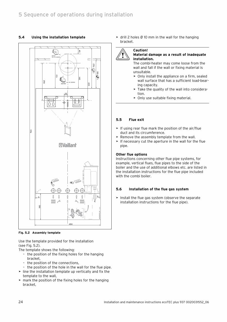
5.4 Using the installation template
00
20
03
99
75_0
0
10
20
0618
0
60/100
140
195
( )
40
60/100
173
276
( )80/125
80/125(Art.-Nr. 303210)
(Art.-Nr. 303910)
55
22
3
25
6
A A
25
A
A A
1176
450
Fig. 5.2 Assembly template
Use the template provided for the installation (see Fig. 5.2).The template shows the following:
the position of the fixing holes for the hanging bracket,the position of the connections,the position of the hole in the wall for the flue pipe.
line the installation template up vertically and fix the template to the wall,mark the position of the fixing holes for the hanging bracket,
–
––
>
>
drill 2 holes Ø 10 mm in the wall for the hanging bracket.
b Caution!Material damage as a result of inadequate installation.The combi-heater may come loose from the wall and fall if the wall or fixing material is unsuitable.
Only install the appliance on a firm, sealed wall surface that has a sufficient load-bear-ing capacity.Take the quality of the wall into considera-tion.Only use suitable fixing material.
5.5 Flue exit
If using rear flue mark the position of the air/flue duct and its circumference.Remove the assembly template from the wall.If necessary cut the aperture in the wall for the flue pipe.
Other flue optionsInstructions concerning other flue pipe systems, for example, vertical flues, flue pipes to the side of the boiler and the use of additional elbows etc. are listed in the installation instructions for the flue pipe included with the combi boiler.
5.6 Installation of the flue gas system
Install the flue gas system (observe the separate installation instructions for the flue pipe).
>
>
>
>
>
>
>
>
5 Sequence of operations during installation

Installation and maintenance instructions ecoTEC plus 937 0020031552_06 25
5.7 Fitting the appliance hanging bracket
1
3
2
Fig. 5.3 Shift load storage tank with hanging bracket
Fix the hanging bracket (1) to the wall using the plugs and screws (2) provided with the appliance.Lift the shift load storage tank out of the packaging (see Section 5.1).Lift the shift load storage tank (3) onto the wall so that it is located slightly above the hanging bracket (1).Slowly lower the shift load storage tank onto the hanging bracket so that the installation carrier on the rear of the unit fully engages in the hanging bracket.
i If the appliance is to be fitted in a timber
framed building ensure that the hanging bracket is secured to a substantial part of the timber frame capable of taking the full weight of the appliance.
>
>
>
>
5.8 Mounting the combination boiler
2
1
Fig. 5.4 Mounting the combi boiler on the shift load storage
tank
Lift the combi boiler out of the packaging (see Sec-tion 5.1).Lift the combi boiler (2) onto the shift load storage tank so that it is located slightly above the shift load storage tank (1).
i Lift the combi boiler at both sides of the base.
Lower the combi boiler slowly onto the hanging bracket on the shift load storage tank so that the installation carrier on the rear of the combi boiler fully engages in the hanging bracket on the shift load storage tank.
>
>
>
Sequence of operations during installation 5

26 Installation and maintenance instructions ecoTEC plus 937 0020031552_06
5.9 Removing the front case
1
2
Fig. 5.5 Removing/fixing the front case
Proceed as follows to remove the front cladding:Release the screw (1) on the base of the unit.Push the two retaining clips (2) on the base of the unit inwards until the front case releases.Hold the front case by the bottom edge, pull forwards and remove the front case from the unit.
5.10 General instructions concerning the heating system
b Caution!Risk of damage to the unit.Residue in the pipes, such as welding beads, scale, hemp, putty, rust and coarse dirt, may be deposited in the appliance and cause mal-functions.
Flush the heating system thoroughly before connecting the appliance in order to remove any possible residue.
i The heating system is fitted with an expan-
sion tank (10 l/0.75 bar).
Before connecting the unit, make sure that this vol-ume is adequate. Otherwise the installation must be fitted with an additional expansion vessel (see Sec-tion 4.8.6).
>
>
>
>
>
5.11 Gas connection
a Danger!Risk of death caused by improper gas installation.An improper gas installation may impair the operational safety of the appliance and result in material damage or personal injury.
The gas installation should only be fitted by a competent person approved at the time by the Health and Safety Executive and in accordance with the gas safety (installation and use) regulations 1998.In doing so, the legal directives and the local regulations for gas supply companies must be observed.
a Danger!Risk of poisoning and explosion due to escaping gas.Possible leaks in the gas line.
Make sure there is no tension in the gas line when it is installed.
b Caution!Risk of damage due to excessive pressure.The gas valve may be damaged by high pres-sure.
Check the tightness of the gas valve using a maximum pressure of 150 mbar.
b Caution!Risk of damage to gas shut-off valves caused by heat transfer.If the final connections are soldered, the heat transferred during the process may damage the gas shut-off valves.
Use extra care when soldering.
>
>
>
>
>
5 Sequence of operations during installation

Installation and maintenance instructions ecoTEC plus 937 0020031552_06 27
2
1
3
62
4
5
1
Fig. 5.6 Gas connection
Proceed as follows for gas connection:Remove the gas connection pipe elbow (2) and gas isolator valve (1) from the packaging.Push the union nut (3) and the olive (4) onto the gas pipe which protrudes from the combi boiler.Push the gas isolator valve (1) onto the gas pipe which protrudes from the combi boiler up to the stop.Pull the union nut (3) with the olive (4) towards the gas isolator valve. Tighten the union nut hand tight.Push the union nut (6) and the olive (5) onto the gas connection pipe elbow (2).Push the gas connection pipe elbow (2) into the gas isolator valve (1) up to the stop.Pull the union nut (6) with the olive (5) towards the gas isolator valve. Tighten the union nut hand tight.The diameter of the pre-formed copper pipe (2) is 22 mm. Connect this pipe to a gas supply pipe having a diameter of not less than 22 mm.
i The gas supply pipework must be of sufficient
size so that, at maximum output, a gas pres-sure of 20 mbar is available at the input to the combi boiler.
Tighten all connections.Purge the gas pipe before commissioning.Check the gas connection for leaks using leak-detect-ing spray.
>
>
>
>
>
>
>
>
>
>
>
5.12 Connecting the hot and cold water
a Danger!Risk of scalding and damage due to leaking water.Possible leaks in water pipes.
Make sure there is no tension in the supply lines when they are installed.
b Caution!Risk of damage to gas shut-off valves caused by heat transfer.If the final connections are soldered, the heat transferred during the process may damage the gas shut-off valves.
Use extra care when soldering.
b Caution!Risk of damage to the appliance.Residue in the pipes, such as welding beads, scale, hemp, putty, rust and coarse dirt, may be deposited in the appliance and cause mal-functions.
Flush the cold water inlet pipe thoroughly before connecting the appliance in order to remove any residue that may be there.
1
2
3
4
5
6
7
Fig. 5.7 Installing the cold water and hot water connections
Remove the two copper tails (5, 6) for water connec-tion, the cold water isolating valve (2) and the union nut (4), olive (3) and fibre seals (1, 7) from the pack-aging.Insert the fibre seal (1) and screw the cold water iso-lating valve (2) to the cold water connection of the shift load storage tank.
>
>
>
>
>
Sequence of operations during installation 5

28 Installation and maintenance instructions ecoTEC plus 937 0020031552_06
Push the union nut (4) with the inserted olive (3) onto the copper tail (5) included with the combi boiler. The diameter of this pipe is 15 mm.Insert the copper tail into the cold water isolating valve up to the stop. Tighten the union nuts in this position.Insert the fibre seal (7) and screw the copper tail (6) which is included with the storage tank module, to the hot water connection on the unit. The diameter of this pipe is 15 mm.Fit the handle for the filling loop to the cold water stop valve (2) with a countersunk screw.
i To operate a circulation pump, we recom-
mend using the accessory setItem. no. 0020057235.
i Using a circulation pump negatively affects
hot water comfort, as it causes turbulence and disrupts the stratification in the tank.
Limit the flow rate of the circulation pump in order to prevent the hot water supply from being negatively affected.
i Using a circulation pump increases energy
consumption.
>
>
>
>
>
5.13 Connecting piping between the stratified storage tank and the combi-heater
2
1
43
Fig 5.8 Piping between shift load storage tank and combina-
tion boiler
Remove the pipe sections (1), (2), (3) and (4) with the associated fibre seals from the box of accessories of the shift load storage tank.Fit the formed pipe and straight pipe sections in the correct sequence.
i The formed pipes (1) and (2) must be fitted
first.
>
>
5 Sequence of operations during installation

Installation and maintenance instructions ecoTEC plus 937 0020031552_06 29
5.14 Connecting the heating supply and return lines
a Danger!Risk of scalding and damage due to leaking water.Possible leaks in water pipes.
Make sure there is no tension in the supply lines when they are installed.
b Caution!Risk of damage to service valves caused by heat transfer.If the final connections are soldered, the heat transferred during the process may damage the service valves.
Use extra care when soldering.
b Caution!Risk of damage to the appliance.Residue in the pipes, such as welding beads, scale, hemp, putty, rust and coarse dirt, may be deposited in the appliance and cause mal-functions.
Flush the heating system thoroughly before connecting the appliance in order to remove any possible residue.
10
1112
13
9
876
12
34
5
Fig. 5.9 Flow and return heating connections
Remove the stop valves with union nuts, olives and fibre seals from the box of accessories for the combi boiler.
>
>
>
>
Insert the fibre seal (1) and screw the stop valve (2) onto the return pipe connection on the combi boiler.Insert the fibre seal (10) and screw the stop valve (9) with the fitted flexible hose (13) onto the flow con-nection of the combi boiler.Fit the O-ring seal (12) to the non-return valve (11).
i Lay the filling loop hose (13) above the pipe-
work elbows.
Push the union nuts (4) and (7) with olives (3) and (8) onto the pre-shaped 22 mm pipes (5) and (6).Push the pipes (5) and (6) into the stop valves up to the stop. Tighten the union nuts in this position.Fit the handle for the filling loop to the cold water stop valve (9) with a countersunk screw.
i Please note that, when fitting a low loss
header the diameter of the connection lines between the unit and the diverter must not be greater than 22 mm.
Ø max. 22 mm
Fig. 5.10 Diameter of the connection lines when using a low
loss header
>
>
>
>
>
>
Sequence of operations during installation 5

30 Installation and maintenance instructions ecoTEC plus 937 0020031552_06
5.15 Installing the condensate drain line
a Danger!Risk of poisoning due to an improperly installed condensate drain line.Blockages in the condensate drain line may cause exhaust gas to escape.
Install the condensate drain line in such a way that blockages are prevented.Leave an access space of at least 180 mm underneath the trap.
a Danger!Risk of poisoning from escaping exhaust gas.If the appliance is operated with an empty condensate trap, exhaust gas may escape and cause poisoning.
Fill the condensate trap with water before initial operation.
The combi boiler is equipped with a condensate siphon. (The filling height is 145 mm.) The siphon collects the condensate in a vessel with a capacity of approx. 200 ml and feeds the entire contents to the Drain line. This min-imises the risk of the Drain line freezing up.
1
2
7
dc
6
5
a
3
4
3
b
Fig. 5.11 Installing the condensate drain line
Connect the condensate drain pipe (1) of the boiler to a condensate drain line (2) which has a minimum internal diameter of 19 mm (22 mm outside diameter for all external pipes) and which is made from an acid-resistant material (e.g. plastic overflow pipe).
i The accessories for the storage tank include
a corrugated hose for draining the conden-sate.
>
>
>
>
i The drain line connected to the condensate
drain pipe of the combi boiler must have a constant gradient (45 mm per metre) and should be installed and terminate within the building to prevent the possibility of freezing up.
The condensate drain line must terminate in a suitable location, e.g.: a) preferably the drain line should run and termi-
nate internally to the house soil and vent stack (at least 450 mm above the invert of the stack). A trap giving a water seal of at least 75 mm (3) (built into the boiler) should be incorporated into the pipe run, and there must be an air break (4) in the drain line upstream of the trap. The connection to the stack should not be made in a way that could cause cross flow into any other branch pipe, or from that branch pipe into the condensate drainpipe. This can be achieved by maintaining an offset between branch pipes of at least 110 mm on a 100 mm diameter stack and 250 mm on a 150 mm diameter stack.
b) connecting into the internal discharge branch (e.g. sink waste or washing machine) with an external termination, the condensate drain line should have a minimum diameter of 22 mm with no length restriction and should incorporate a trap with a 75 mm (3) (built into the boiler) seal. The connection should preferably be made down stream of the sink waste trap. If the con-nection is only possible upstream, then an air break is needed between the two traps. This is normally provided by the sink waste.
c) terminating in a gully (5) below grid level (6) and above the water level. The external pipe length should be kept as short as possible to minimise the risk of freezing and should not be more than 3 m.
d) at a condensate absorption point (soakaway) (7). The external pipe length should not be more than 3 m.
Further information can be obtained from "BS 6798 Specification for installation of gas–fired boilers of rated input not exceeding 70 kW net“. The condensate siphon must be filled with water as described in Section 6.6 before the combi boiler is commissioned.
5 Sequence of operations during installation

Installation and maintenance instructions ecoTEC plus 937 0020031552_06 31
min.180
Fig. 5.12 Installation space condensate siphon
There must be a minimum clearance of 180mm below the siphon for access.
5.16 Connecting the drain pipe to the pressure relief valve
4
3
2
1
Fig. 5.13 Installing the discharge pipe
The pressure relief for the heating system is integrated into the boiler.
Remove the discharge pipe with union nut and rubber seal from the box of accessories for the shift load storage tank.Insert the rubber seal (1) into the union nut (2) and screw the discharge (3) onto the pressure relief valve (4).The discharge pipework should be as short as possi-ble with a continuous fall from the appliance.The discharge pipe should terminate in such a way that nobody can be injured and no cable or other electrical components can be damaged if water or steam is discharged. Please note that the end of the discharge pipe must be visible.
>
>
>
>
i We recommend that the discharge pipe for
the pressure relief valve is not shortened.
5.17 Connecting the drain hose to the pressure relief valve of the stratified storage tank
1
2
Fig. 5.14 Storage tank pressure relief discharge pipe connec-
tion
The safety valve for the hot water system is integrated in the shift load storage tank.
Remove the flexible drain hose from the box of accessories for the shift load storage tank.Push the drain hose (1) onto the safety valve (2).
The end of the drain hose can be directed via an open connection to a tundish and terminated in a similar manner to the boiler pressure relief discharge pipe.
5.18 Connecting the exhaust gas system to the combi-heater
Refer to the separate air/flue duct installation instructions included with the appliance.
>
>
>
Sequence of operations during installation 5

32 Installation and maintenance instructions ecoTEC plus 937 0020031552_06
5.19 Electrical connection
5.19.1 General requirements
e Danger!Risk of fatal electric shock from live con-nections.Voltage is continuously present in the L and N terminals of the turquoise coloured plug, even when the main switch is turned off.
Before working on the switch box, always switch off the power supply to the appli-ance by removing the mains plug from the socket or by disconnecting the optional cir-cuit breaker.
e Danger!Risk of electrocution as a result of an improper electrical connection.An improper electrical connection may nega-tively affect the operational safety of the appliance and result in material damage or personal injury.
The electrical installation must be fitted by a competent person who is responsible for complying with the existing standards and guidelines.Connect the appliance in accordance with BS 7671 (IEE Regulations).For IE: Observe the current ETCI regula-tions (Electro Technical Council for Ire-land).Observe the corresponding installation instructions for the electrical connection of ecoTEC combi-heaters.Earth the appliance.
b Caution!Risk of damage to the appliance.The electronics may be damaged via a mains supply at terminals 7, 8, 9 and "BUS".
Only connect the mains supply cable to the terminals marked for the purpose.
The appliance is designed for connection to 230 V, ~ 50 Hz supply with a 3 A rating. Connection to the mains supply shall be made via a fused 3 pin plug to an unswitched shuttered, and should comply with BS 1363. (Alternatively the connection can also be carried out with a 3 A fused two-pole isolator, whose contact sepa-ration at all poles is at least 3 mm and which supplies only the appliance and controls). The connection must permit complete isolation of the appliance and its con-nected controller from the mains supply. It should be easily accessible and be located in the proximity of the combi boiler. Use a three core flexible cable in accord-
>
>
>
>
>
>
>
ance with BS 6500, Tables 6, 8 or 16 (3 x 0.75 to 3 x 1.5 mm2).
i Ensure that all wiring passes through the
cable clamps in the rear of the control box and are securely fixed.
Check that when connecting the mains wiring that the current carrying conductors become taut before the earth conductor should the supply cable slip from the cable clamp.
5.19.2 Establishing the electrical connection for the stratified storage tank
b Caution!Risk of cable damage.Cables may become damaged if they come into contact with hot parts of the appliance.
Observe the routing of the cable.
X12
X31
1
2
Fig. 4.15 Opening the electronics box
>
>
5 Sequence of operations during installation
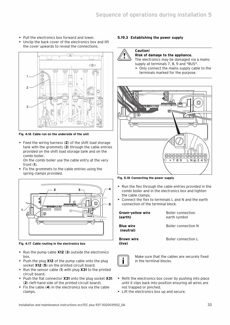
Installation and maintenance instructions ecoTEC plus 937 0020031552_06 33
Pull the electronics box forward and lower.Unclip the back cover of the electronics box and lift the cover upwards to reveal the connections.
1
2
3
Fig. 4.16 Cable run on the underside of the unit
Feed the wiring harness (2) of the shift load storage tank with the grommets (3) through the cable entries provided on the shift load storage tank and on the combi boiler. On the combi boiler use the cable entry at the very front (1).Fix the grommets to the cable entries using the spring clamps provided.
- + 7 8 9 L N 3 4 5
X31
X121
2 3
5
4
Fig. 4.17 Cable routing in the electronics box
Run the pump cable X12 (3) outside the electronics box.Push the plug X12 of the pump cable onto the plug socket X12 (5) on the printed circuit board.Run the sensor cable (1) with plug X31 to the printed circuit board.Push the flat connector X31 onto the plug socket X31 (2) (left-hand side of the printed circuit board).Fix the cable (4) in the electronics box via the cable clamps.
>
>
>
>
>
>
>
>
>
5.19.3 Establishing the power supply
b Caution!Risk of damage to the appliance.The electronics may be damaged via a mains supply at terminals 7, 8, 9 and "BUS".
Only connect the mains supply cable to the terminals marked for the purpose.
- + 7 8 9 L N 3 4 5
- + 7 8 9 L N 3 4 5
Fig. 5.18 Connecting the power supply
Run the flex through the cable entries provided in the combi boiler and in the electronics box and tighten the cable clamps.Connect the flex to terminals L and N and the earth connection of the terminal block.
Green-yellow wire(earth)
Boiler connectionearth symbol
Blue wire (neutral)
Boiler connection N
Brown wire (live)
Boiler connection L
i Make sure that the cables are securely fixed
in the terminal blocks.
Refit the electronics box cover by pushing into place until it clips back into position ensuring all wires are not trapped or pinched.Lift the electronics box up and secure.
>
>
>
>
>
Sequence of operations during installation 5

34 Installation and maintenance instructions ecoTEC plus 937 0020031552_06
5.19.4 Connection diagrams
Burner cable harness
Wiring harness hydraulics
Connection for external eBUS controller
Room thermostat 24 V:Connection 7, 8 und 9No bi-directional interface(only analogue)
Room thermostat 230 V/50 Hz(Remove bridge when connecting)
Heating pump2 speed pump (plug with 5 pins)
Mains connection 230 V/50 Hz
Fuse 2 A, slow-acting
Igniter
Attention:Do not connect mains voltageDanger of destroying the electronics!
Diagnosis via eBUS, vrnetDIALOG
Accessory module connection
External sensor
external feed or return line sensor
Shift load storage tank pump connection 230 V
Shift load storage tank connectionShift load storage tank pump connection
Fig. 5.19 Connection diagram electronics box
5 Sequence of operations during installation

Installation and maintenance instructions ecoTEC plus 937 0020031552_06 35
X 2
BUS— +
24V7 8 9
230VL N 3 4 5X 20
X40
X3
1
X12
X41
Electronics box
Hot water outlet (NTC)
Fan
Ignition electrodeFlow temperature sensor (NTC)
Diverter valve
Gas valve
Water pressure sensor
Return temperature sensor (NTC)
X 20/5 red
X 20/7 black
X 20/7 black
X 20/8 blue
X 2/12 green
X 2/11 red
X 2/9 black
Pump
X 20/18 red (24 VDC)
X 20/9 blue (Erde)
X 20/16 blue (Earth)
X 20/13 black
X 20/12 black
X 20/4 grey (PWM)
X 20/3 black (Hall-Signal)
X 20/17 red (24 VDC)
X 2/15 brown C
X 2/8 blue D
X 2/16 black A
X 2/7 pink B
X 2/3 red (+ 5V)
X 2/2 black (Earth)
X 2/6 Green (Signal)
X 2/5 violet (Signal)
X 2/1 black
Plate heat exchanger (NTC)
X 2/4 orange
X 2/10 black
Thermal fuse
Plug connection
Fig. 5.20 Connection diagram combi boiler
Sequence of operations during installation 5
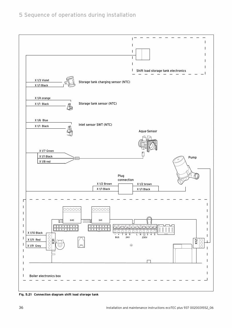
36 Installation and maintenance instructions ecoTEC plus 937 0020031552_06
BUS— +
24V7 8 9
230VL N 3 4 5
X3
1
X12
Boiler electronics box
Storage tank charging sensor (NTC)X 1/3 Violet
X 1/1 Black
Pump
X 1/7 Green
X 1/1 Black
X 1/8 red
Storage tank sensor (NTC)
X 1/4 orange
X 1/1 Black
Plug connection
Aqua-Sensor
Shift load storage tank electronics
X 1/2 brown
X 1/1 Black
X 1/2 Brown
X 1/1 Black
X 1/6 Blue
X 1/1 Black Inlet sensor SWT (NTC)
X 1/10 Black
X 1/11 Red
X 1/9 Grey
X40 X41
Fig. 5.21 Connection diagram shift load storage tank
5 Sequence of operations during installation
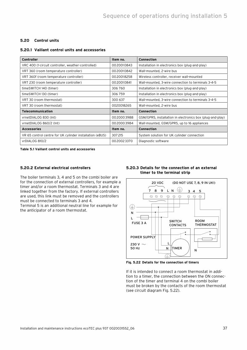
Installation and maintenance instructions ecoTEC plus 937 0020031552_06 37
5.20 Control units
5.20.1 Vaillant control units and accessories
Controller Item no. Connection
VRC 400 (1-circuit controller, weather-controlled) 00 2001 0843 Installation in electronics box (plug-and-play)
VRT 360 (room temperature controller) 00 2001 0842 Wall-mounted, 2-wire bus
VRT 360f (room temperature controller) 00 2001 8258 Wireless controller, receiver wall-mounted
VRT 230 (room temperature controller) 00 2001 0841 Wall-mounted, 3-wire connection to terminals 3-4-5
timeSWITCH 140 (timer) 306 760 Installation in electronics box (plug-and-play)
timeSWITCH 130 (timer) 306 759 Installation in electronics box (plug-and-play)
VRT 30 (room thermostat) 300 637 Wall-mounted, 3-wire connection to terminals 3-4-5
VRT 30 (room thermostat) 0020018265 Wall-mounted, 2-wire bus
Telecommunication Item no. Connection
vrnetDIALOG 830 (Int) 00 2000 3988 GSM/GPRS, installation in electronics box (plug-and-play)
vrnetDIALOG 860/2 (Int) 00 2000 3984 Wall-mounted, GSM/GPRS, up to 16 appliances
Accessories Item no. Connection
VR 65 control centre for UK cylinder installation (eBUS) 307 215 System solution for UK cylinder connection
vrDIALOG 810/2 00 2002 3370 Diagnostic software
Table 5.1 Vaillant control units and accessories
5.20.2 External electrical controllers
The boiler terminals 3, 4 and 5 on the combi boiler are for the connection of external controllers, for example a timer and/or a room thermostat. Terminals 3 and 4 are linked together from the factory. If external controllers are used, this link must be removed and the controllers must be connected to terminals 3 and 4.Terminal 5 is an additional neutral line for example for the anticipator of a room thermostat.
5.20.3 Details for the connection of an external timer to the terminal strip
3987
POWER SUPPLY
230 V 50 Hz
L
L
L N
N
NN
20 VDC (DO NOT USE 7, 8, 9 IN UK!)
FUSE 3 A SWITCH CONTACTS
ROOM THERMOSTAT
TIMER
4 5
Fig. 5.22 Details for the connection of timers
If it is intended to connect a room thermostat in addi-tion to a timer, the connection between the ON connec-tion of the timer and terminal 4 on the combi boiler must be broken by the contacts of the room thermostat (see circuit diagram Fig. 5.22).
Sequence of operations during installation 5

38 Installation and maintenance instructions ecoTEC plus 937 0020031552_06
5.20.4 Optional plug-in timers by Vaillant
Further details for the connection can be found in the relevant instructions of the accessories. The cover on the electronics box should be replaced after all the elec-trical connections have been made. The cover is secured with two clips.
5.21 Thermostatic radiator valves
The combi boiler is equipped with an automatic adjusta-ble by-pass valve which makes it ideal for use in sys-tems with thermostatic radiator valves (an additional by-pass valve is not required). In the interests of opti-mum fuel economy, if thermostatic radiator valves are fitted they must be used in conjunction with a interlock block on the combi boiler. A programmable room ther-mostat or separate timer and room thermostat will ensure complete boiler shutdown when the heating demand is satisfied. (The radiator in the room contain-ing the room thermostat should not be fitted with a TRV.)
5.22 Frost prevention
The combi boiler is equipped with an integrated frost protection thermostat for protecting the combi boiler. Additional protection measures must be taken to pre-vent external or exposed parts of the heating system and the house, for example the fitting of an external frost protection thermostat. This frost protection ther-mostat should be connected to the terminals 3 and 4 on the combi boiler, in parallel to all the other external heating controllers.
i External frost protection devices cannot be
used if plug-in timers are used.
5.23 Heating pump
The combi boiler is fitted with a heating pump which is fully wired (additional cabling is not necessary). The pump has automatic overrun time after the combi boiler has switched off.
5.24 Anti-cyclic "Economiser" control system
The combi boiler is fitted with an anti-cyclic controller which ensures that energy wasting short term running of the combi boiler cannot occur. The controller pre-vents the combi boiler from switching on again within a preset time period after the last switch-off of the cen-
tral heating. (Hot water preparation is not affected by this function. Hot water can be drawn off at any time.)
i For temporary cancellation of this switch-on
protection system, turn the main switch ON/OFF of the combi boiler to position "0" and then a few seconds later switch to posi-tion "l".
5.25 Automatic pump spin control
The combi boiler is fitted with an internal controller which causes the fitted heating pump to switch on once in a 23 hour period and also operates the diverter valve. This controller prevents the jamming up of these com-ponents if the combi boiler is inactive for long periods. This controller is inactive if the power supply to the unit is switched off
5 Sequence of operations during installation

Installation and maintenance instructions ecoTEC plus 937 0020031552_06 39
6 Commissioning, Part I
6.1 Preparatory checks of the electrical system
Check the electrical installation for short circuits, proper earthing and earth resistance and for correct polarity.
6.2 Gas supply
a Danger!Risk of explosion caused by escaping gas.When the gas line is bled, gas may leak and possibly ignite.
Provide adequate ventilation whilst doing the work.Extinguish all naked flames.Do not smoke while bleeding the gas line.
The entire gas installation including the gas meter must be inspected, checked for leaks and purged in accord-ance with BS 6891. In the Irish Republic (IE) in accord-ance with the current version of IS 813.
Purge the gas supply by opening the gas isolator valve under the unit.After purging re-tighten the gas isolator valve and check for leaks. (The combi boiler itself does not need to be purged.) This takes place through the automatic burner ignition monitoring system.
6.3 Cold water supply
Open all the domestic hot water taps supplied by the appliance.Open the mains water isolating valve supplying the appliance.Open the cold water isolating valve under the appli-ance. The water then flows through the combi boiler and the shift load storage tank to the hot water taps.Close all the hot water taps one after the other start-ing with the lowest one until the hot water pipework is vented. Check all hot and cold water pipes for leaks.
6.4 Filling and bleeding the heating system
i Use the following test programmes for filling
and venting the heating system:
Filling the heating systemUse the test programme P.6 for filling the heating system:
>
>
>
>
>
>
>
>
>
>
>
>
The diverter valve moves to the central position, the heating pump is not running and the unit does not go into heating mode.
Use the test programme as described in Section 9.2.
Bleeding the heating systemUse the test programme P.0 to vent the combi boiler, the heating system and the hot water circuit.
The unit does not go to heating mode, the heating pump runs intermittently and alternately vents the heating cir-cuit and the hot water circuit.
Use the test programme as described in Section 9.2.
6.4.1 Checking the fill pressure in the heating system
bar
bar1
2
Fig. 6.1 Checking the filling pressure of the heating system
i The ecoTEC plus 937 is supplied fitted with a
pressure gauge and a digital pressure display.Using the pressure gauge you can perform a quick check whether the filling pressure is within the prescribed range or not, even when the unit is switched off.With the unit switched on, you can read off the exact pressure by pushing the button "-" (2).
For proper operation of the heating system, when the installation is cold, the pointer on the pressure gauge (1) should be in the dark-grey area. This corresponds to a filling pressure between 1.0 and 2.0 bar. If the pointer is in the light grey area, top up with water.If the heating system extends over several storeys, the system may require a higher filling pressure.
>
>
>
Commissioning, Part I 6

40 Installation and maintenance instructions ecoTEC plus 937 0020031552_06
6.4.2 Filling device for ecoTEC plus 937
The ecoTEC plus 937 is fitted with a filling loop.Push the double check (1) of the filling loop into the cold water stop valve (2) and secure the double check valve (1) with the spring clip (4).First open the stop valve to perform the filling (3).Open the cold water stop valve (2) so that the water flows into the heating system. Fill the heating system as described in Section 6.4.3.After filling close both stop valves and remove the filling loop by pulling the double check valve (1) off the cold water stop valve (2) (see Fig. 6.2).
3
14
2
Fig. 6.2 Filling device
i Both stop valves must be closed during the
operation of the heating system and the fill-ing loop must be removed from the double check valve again.
>
>
>
>
1 2
Fig. 6.3 Double check valve separated from the system during
the heating process
6.4.3 Filling the heating system for the first time
i If the water pressure in the heating system is
too low the display switches between error message “F.22” and the display of the actual pressure when the unit is switched on.
Fill the heating system as follows:Open all thermostatic radiator valves.Check that both stop valves on the combi boiler are open.Connect the filling loop as described in Section 6.4.2.Open the water stop valve.Slowly open the isolator valve in the filling loop so that water can flow into the heating system. Bleed the radiator at the lowest point until water flows out of the bleed valve without bubbles.Bleed all other radiators until the heating system is completely filled with water, all bleed valves have been shut and the manometer pointer is in the centre of the dark grey area. Bleed the heating pump by loosening the central screw. Close the filling loop valve and the cold water stop valve.Loosen the cap on the automatic air vent by a couple of turns. (In continuous mode the unit is vented inde-pendently by the automatic air vent system.)Check all connections and the entire system for leaks.
>
>
>
>
>
>
>
>
6 Commissioning, Part I

Installation and maintenance instructions ecoTEC plus 937 0020031552_06 41
6.5 Flushing the system for the first time ("cold")
i The entire heating system must be flushed
through completely at least twice: once cold and once hot, in accordance with the follow-ing instructions.
Check if all radiator thermostat valves and both stop valves on the combi boiler are open.Connect a hose to the drain valve which is located at the lowest position in the heating system.Open the 1/2“ drain valves and all the bleed valves on the radiators so that the water flows quickly and completely out of the heating system and the combi boiler, in order to remove the contamination caused during the installation out of the heating system before the combi boiler is started up.Close the 1/2” drain valves and radiator bleed vavles.Re-fill the heating system with water as described in Section 6.4.3.Check that the pressure relief valve in the heating system is functioning correctly by turning the handle on the valve.Check the pressure in the heating system and top up with water if necessary.Close the filling loop valve and the cold water stop valve.
6.6 Filling the condensate drain trap
a Danger!Risk of poisoning from escaping exhaust gas.If the appliance is operated with an empty condensate trap, exhaust gas may escape and cause poisoning.
Before initial operation, fill the condensate trap with water as follows.
Remove the lower section (1) of the condensate siphon by turning the bayonet connection in a coun-terclockwise direction a quarter of a turn.Fill the lower section with water until about 10 mm below the upper edge.Replace the lower section of the condensate siphon.
>
>
>
>
>
>
>
>
>
>
>
>
1
Fig. 6.4 Filling the condensate siphon
6.7 Setting the pump output
Only in ecoTEC plus appliances:The output of the two-speed pump can be matched to the requirements of the heating system. If required, change the pump output, depending upon the setting of the operating mode, under diagnostic number "d.19“ (see Section 9.1.2).
6.8 Adjusting the bypass
The appliance is equipped with an adjustable bypass valve. The pressure can be set between 170 and 350 mbar. The valve is pre-set to approx. 250 mbar (mid-position). Each turn of the setting screw changes the pressure by approx. 10 mbar. The pressure is increased by turning to the right and reduced by turning to the left.
1
Fig. 6.5 Setting the bypass valve
Use the adjusting screw (1) to adjust the bypass valve.
>
Commissioning, Part I 6

42 Installation and maintenance instructions ecoTEC plus 937 0020031552_06
6.9 Checking the gas setting
a Caution!Malfunctions or reduction in working life of the boiler!If the boiler version does not correspond to the local gas family, there will be malfunc-tions or you have to change components of the boiler ahead of schedule, e. g. do not use a LPG boiler on natural gas.
Before starting up the boiler compare the details of the type of gas specified on the identification plate with the type of gas supplied at the installation site.
If the boiler version corresponds to the local gas family:Proceed as described below.
If the boiler version does not correspond to the local gas family:
Perform the gas conversion in accordance with the gas conversion kit 0020010641.Adjust the gas setting as described below (see sections 6.9.1 to 6.9.3).
The combustion of this boiler has been checked, adjusted and preset at the factory for operation on the type of gas defined on the identification plate. No meas-urement of the combustion is necessary to set up the boiler.
Do not adjust the multifunctional automatic gas valve.Ensure
that the boiler has been installed in accordance with these instructions,the integrity of the flue system and the flue seals, as described in the flue installation instructions enclosed with this boiler, and as described below,a visual check is carried out on the boiler combus-tion circuit and the relevant seals,that any defects have been corrected at this stage.
To further validate the integrity of the flue system and confirm correct operation of the boiler it is possible to conduct flue gas and air measurements on this boiler - for details see section 6.9.1.
Proceed to put the boiler into operation as follows:
Check the maximum gas flow rate as detailed in sec-tion 6.9.2.Check the gas inlet working pressure as detailed in section 6.9.3.Note that you must re-measure the gas flow rate or the gas inlet working pressure, if changes were required to correct any issues found.
>
>
>
>
>
>
–
–
–
–
>
>
>
6.9.1 Checking for tightness of the flue gas installation and flue gas recirculation
Check the integrity off the flue gas installation according to TB 200.Should the flue gas installation be longer than 2 m we strongly recommend to check the system for flue gas recirculation as described below.
1
2
Fig. 6.6 Flue gas and air measure points
Legend:1 Flue gas measure point2 Air measure point
For checking the system for recirculation use the air measure point (2).Use the flue gas analyser.If you detect any CO or CO
2 in the fresh air, search
for the flue gas leakage or recirculation.Correct the defects.Check again as described before, if there is any CO or CO
2 in the fresh air.
If you cannot correct the defects you must not start up the boiler.
>
>
>
>
>
>
>
>
6 Commissioning, Part I

Installation and maintenance instructions ecoTEC plus 937 0020031552_06 43
6.9.2 Checking the gas flow rate
The boiler is fitted with a multifunctional automatic gas valve which ensures that the precise air/gas ratio is pro-vided under all operating conditions. The gas flow rate has been set during production and does not require adjustment. With the front casing fitted check the gas flow rate of the boiler as follows:
Start the boiler by activating the test program P.1 as described in section 9.2.In addition, ensure that maximum heat can be dissi-pated into the heating system by turning up the room thermostat.Alternatively, fully open the hot water taps to ensure full flow rate through the boiler.Wait at least 5 minutes until the boiler has reached its operating temperature.Ensure that all other gas appliances in the property are turned off.Measure the gas flow rate at the gas meter.Check that the gas flow rate is as stated in Table 6.1.
Nominal net heat input in
kW as per
BS EN 483
Gas flow rate
Natural gas in m3/h Propane in kg/h
nominal + 5 % - 10 % nominal + 5 % - 10 %
37.8 4.00 4.20 3.60 2.94 3.09 2.65
Table 6.1 Gas flow rate
If the measured gas flow rate lies outside the toler-ance limits specified in Table 6.1, do not operate the boiler and inform the Vaillant Service Solutions (0870 6060 777).
If the measured gas flow rate is within the tolerance lim-its shown in Table 6.1, then proceed as follows:
Take the boiler out of operation byPressing the “+” and “i” buttons simultaneously and turn down both thermostat control knobs.Allow the boiler to cool down by turning off water taps and allow pump overrun to operate for a mini-mum of two minutes.
Record the boiler maximum gas flow rate onto the Benchmark gas boiler commissioning checklist.
6.9.3 Checking the gas inlet working pressure
Ensure that the gas inlet working pressure can be obtained with all other gas appliances in the property working.Remove the front casing from the boiler.Close the gas isolation valve of the boiler.
>
>
>
>
>
>
>
>
>
–
–
>
>
>
>
1
2
Fig. 6.7 Measuring the gas inlet working pressure
Loosen the sealing screw marked “in” (1) on the gas valve.Connect a digital pressure gauge or U-tube manome-ter (2).Open the gas isolation valve of the boiler.Start the boiler by activating the test program “P.1” as described in section 9.2.In addition, ensure that maximum heat can be dissi-pated into the heating system by turning up the room thermostat.Alternatively, fully open the hot water taps to ensure full flow rate through the boiler.With the boiler operating at full load check that the gas inlet working pressure at the reference test point (1) complies with the requirements of Table 6.2.
Natural gas (G20) LPG (G31)
Minimum pressure at
reference test point in mbar
Maximum pressure at
reference test point in mbar
Minimum pressure at
reference test point in mbar
Maximum pressure at
reference test point in mbar
15 23 23 43
Table 6.2 Gas inlet working pressures at the reference test
point
Should the pressure recorded at the reference test point in the boiler be lower than indicated (Table 6.2)
>
>
>
>
>
>
>
>
Commissioning, Part I 6

44 Installation and maintenance instructions ecoTEC plus 937 0020031552_06
check if there is any blockage in the pipework or if the pipework is undersized.If the supply pressure is out of tolerance contact your Emergency Service Provider.
If the gas inlet working pressure at the reference test point (1) is not within the permissible range and you cannot correct the failure, notify the gas supply com-pany or the Vaillant Service Solutions team and proceed as follows:
Take the boiler out of operation byPressing the “+” and “i” buttons simultaneously and turn down both thermostat control knobs.Allow the boiler to cool down by turning off water taps and allow pump overrun to operate for a mini-mum of two minutes.
Close the gas isolation valve of the boiler.Remove the pressure gauge and re-tighten the seal-ing screw (1).Turn on gas at the gas isolation valve.Make sure that there is no leakage at the sealing screw.Turn off gas at the gas isolation valve.Put the front casing back on.Turn off electrical supply to the boiler.You must not start up the boiler.
If the gas inlet working pressure is within the permissi-ble range, proceed as follows:
Take the boiler out of operation byPressing the “+” and “i” buttons simultaneously and turn down both thermostat control knobs.Allow the boiler to cool down by turning off water taps and allow pump overrun to operate for a mini-mum of two minutes.
Close the gas isolation valve of the boiler.Remove the pressure gauge and re-tighten the seal-ing screw (1).Open the gas isolation valve of the boiler.Make sure that there is no leakage at the sealing screw.Put the front casing back on.Reset boiler controls for normal operation.Record the appliance gas inlet working pressure (mbar) in the Benchmark gas boiler commissioning checklist.
>
>
–
–
>
>
>
>
>
>
>
>
>
>
–
–
>
>
>
>
>
>
>
6.10 Assembling the front panel
1
2
Fig. 6.8 Fitting the front casing
Hook the front casing section into the tabs at the top of the frame of the combi boiler and slide the lower section of the casing into the position provided.Make sure that the spring clips (2) engage properly.Tighten the securing screw of the enclosure (1).
6.11 Adjusting the central heating system (range rating)
The appliance is fully modulating for central heating and it is therefore not necessary to range rate the appli-ance. However if desired it is possible to range rate the boiler as follows:
Press the "i“ and "+“ buttons simultaneously.Hold the button "+“ down until "d.0“ is displayed.
i The display runs from "d.0“ to "d.99“ and
then starts again at "d.0“.
Press the "i" button. The symbol "=“ is displayed. Then the part load setting is shown in kW.Use the buttons "+“ and "–“, to increase or decrease the displayed value in steps of 1 kW. The displayed value flashes during the setting process. The availa-ble setting ranges are shown in Table 6.3.Push the button "i“ for about five seconds or until the display stops flashing. This stores the value in the memory. The display reverts back to the normal sta-tus (display of current feed temperature, for example 45 °C).To de-activate the setting mode, simultaneously push the buttons "i“ and "+“.
>
>
>
>
>
>
>
>
>
6 Commissioning, Part I

Installation and maintenance instructions ecoTEC plus 937 0020031552_06 45
The setting mode is also de-activated if a button is not pushed within a period of 4 minutes.
Appliance Heating output in kW
ecoTEC plus 937 12 - 28
Table 6.3 Setting the part load ranges of the heating system
6.12 Converting the gas type
i To convert the appliance from natural gas to
liquid gas you will need the Vaillant modifica-tion kit Part No. 00 2001 0641.To convert the appliance from liquid gas to natu-ral gas you will need the Vaillant modification kit Part No. 00 2001 0642.Perform the conversion of the appliance in accordance with the description in the modi-fication set.
7 Commissioning Part II: Functional checks
7.1 Functional checks
7.1.1 Method of procedure
After installing and setting the gas, perform a function check before commissioning the appliance and handing over to the user.
Commission the appliance in accordance with the instructions in the relevant operating manual.Check the gas supply pipework, the flue system, the heating system and the hot water pipework for leaks.Check that the flue system is properly fitted in accordance with the installation instructions for the flue system.Check the ignition and whether the burner is showing a consistent flame picture.Carry out a function check of the heating system (see Section 7.1.2) and the hot water preparation (see Sec-tion 7.1.3).Hand over the appliance to the user (see Section 7.2).
Fig. 7.1 Function check
7.1.2 Heating
Switch on the appliance.Make sure that there is a heat demand.Press "i" to activate the status indicator.
As soon as there is a heat demand the display runs through status indications "S. 1" to "S. 3", until the appliance is running properly in normal operation and the display shows "S. 4".
>
>
>
>
>
>
>
>
>
Commissioning, Part I 6Commissioning Part II: Functional checks 7

46 Installation and maintenance instructions ecoTEC plus 937 0020031552_06
Fig. 7.2 Display in heating mode
7.1.3 Hot water operation
Switch on the appliance.Open the hot water tap fully.Press "i" to activate the status indicator.
If the hot water operation is operating properly, the dis-play shows "S.14".
Fig. 7.3 Display during hot water preparation
7.1.4 Storage tank charging
i The storage tank charging is delivered de-
activated and must be activated during com-missioning.
The storage tank charging of the shift load storage tank is only active if the warm start function is switched on.
This is shown by the symbol in the display.With the storage tank charging function switched on you can set the following temperatures using the knob for hot water draw-off temperature:
Knob setting "b“ 50 °CKnob setting "a“ 65 °C
With the storage tank charging function switched off you can set the following temperatures using the knob for hot water draw-off temperature:
>
>
>
–
––
Knob setting "c“ 35 °CKnob setting "a“ 65 °C
a
a
bc
c
1
1
1
Fig. 7.4 Setting range for the storage tank temperature
If the storage tank charging function is switched off the storage tank is not held at temperature. In this case the unit switches on when water is drawn off and operates on a through-flow principle.
a Danger!Risk of scalding caused by the Legionella protection function.The appliances are fitted with an automatic Legionella protection control:If the temperature falls below 50 °C in the domestic hot water cylinder, the cylinder is heated up to 70 °C once every 24 hours. In such a case, there is a risk of scalding when drawing water.
Please note when drawing water that it can be very hot.
The Legionella protection control can be de-activated in the diagnosis level "d.74“.
Activating the storage tank chargingSwitch on the appliance.Activate the storage tank charging by turning the hot water temperature control knob fully clockwise.
––
>
>
>
7 Commissioning Part II: Functional checks

Installation and maintenance instructions ecoTEC plus 937 0020031552_06 47
The symbol " “ is displayed.Turn the hot water temperature control knob to the temperature you require.Press "i" to activate the status indicator.
During the storage tank charging the display shows "S.24“.
Fig. 7.5 Display during storage tank charging
i When operating the appliance in the winter,
the tank charging function is limited in order to prevent the heating installation from cool-ing down. The maximum tank charging time is set to 45 minutes by the manufacturer. Your heating engineer can alter this setting via diagnostic point "d.75".
De-activating the storage tank chargingDe-activate the storage tank charging by turning the hot water temperature control knob fully anti-clock-wise.
The symbol " “ disappears.Then set the desired hot water temperature. The unit now operates in the through-flow principle, the stor-age tank is not held at temperature.
7.1.5 Conclusive flushing of the heating system ("hot")
Allow the appliance to run until both the appliance and the heating system have reached their operating temperature.Check the heating system for leaks.Connect a hose to the drain valve which is located at the lowest position in the heating system.Shut off the appliance, open the drain valve and all vent valves on the radiators and allow the water to flow out of the heating system and the combi boiler quickly and fully.Close the drain valve.Re-fill the heating system with water as described in Section 6.4.3.Drain water out of the system until a system pressure of 1.0 bar is reached. (The ideal measured value on the pressure gauge is 0.5 bar plus an extra amount
>
>
>
>
>
>
>
>
>
>
>
corresponding to the highest point of the system above the combi boiler. A height of 10 m corresponds to a pressure increase on the pressure gauge of around 1 bar. The pressure must not be less than 1 bar on any installation.) If the system is to be protected by an inhibitor, it should be added at this stage in accordance with the manufacturer's instructions.Further information can be obtained from Sentinel, Betz Dearborn Ltd., Tel.: 0151 420 9595, or from Fer-nox, Alpha–Fry technologies, Tel.: 0870 8700362.Re-fit the enclosure of the combi boiler (see Section 6.10).Fit the base cover to the combi boiler and shift load storage tank by pushing the front edge of the cover into the retaining tag on the front lower edge of the unit framework. Carefully push the base cover upwards until the spring clips on the side of the unit engage.It may be necessary to modify the base cover by removing the easily removable breakaway sections.
7.2 Briefing users
i When installation is complete, attach the sup-
plied sticker (item no. 835 593) in the user’s language to the front of the appliance.
Set the controller for the maximum radiator tempera-ture to the required temperature.Set the controller for the maximum hot water tem-perature to the required temperature.Instruct the operator in the safe and efficient opera-tion of the combi boiler, paying particular attention to the functions of:
the ON/OFF switch of the combi boiler,the controller for the maximum radiator tempera-ture,the controller for the maximum hot water temper-ature,the pressure gauge.
Make the operator acquainted with the operation of any external controllers.Explain to the operator the importance of regular maintenance by a competent heating engineer.It is strongly recommended that a maintenance con-tract be taken out to ensure regular maintenance. Further information can be obtained from Vaillant Service Solutions (0870 6060 777).Enter the operating pressure of the central heating system, the heat input (in kW) and the temperature difference between the flow and return in the Bench-mark gas boiler commissioning checklist.If the appliance is not installed and commissioned in accordance with manufacturer's instructions this can lead to invalidation of the guarantee (Note: Your legal rights remain unaffected by this.)
>
>
>
>
>
>
>
––
–
–>
>
>
Commissioning Part II: Functional checks 7

48 Installation and maintenance instructions ecoTEC plus 937 0020031552_06
Leave the operating and installation instructions with the operator of the appliance. Go through the operating manual with the user and answer any questions.Draw special attention to the safety instructions, which the user must follow.Instruct the user about the methods used for com-bustion air supply and flue conducting. In particular, point out that these measures must not be altered.Inform the user that the instruction manuals should be kept near the appliance.
7.3 Factory guarantee
Two year guarantee for ecoTEC plus appliancesVaillant undertakes to rectify any manufacturing defect that occurs within twenty-four months of the installa-tion date.For the 2nd year of the guarantee to be valid an annual service must be carried out by a competent person approved at the time by the Health and Safety Execu-tive one year after installation.The cost of this annual service is not included in the guarantee.
Registering with usRegistration is simple. Just complete the Guarantee Registration Card and return to Vaillant within 30 days of installation. Your details will then be automatically registered within the Vaillant scheme.Note: No receipt will be issued.
Immediate helpIf your Vaillant boiler develops a fault your first action should be to contact your installer, as his professional assessment is needed under the terms of our Guaran-tee.If you are unable to contact your installer, phone Vail-lant Service Solutions: 0870 6060 777
>
>
>
>
>
8 Inspection and maintenance
8.1 Inspection and maintenance intervals
a Danger!Risk of injury and risk of damage to prop-erty due to neglected inspection and main-tenance!Neglected inspection and maintenance works or not observing the stated inspection and maintenance intervals can interfere with the operational safety of the boiler and can result in damage to property and to persons.
Point out to the operator that he must observe the demanded inspection and maintenance intervals as a minimum.Carry out proper regular inspections once a year.Carry out regular maintenance as dictated by findings during the inspection process.The frequency of maintenance must not be longer than every 5 years.
a Danger!Danger of life and limb due to improper inspection/maintenance!Inspections/Maintenance work carried out improperly can result in leakages and explo-sion.
The boiler may only be inspected/main-tained by a competent person.
All service work must be carried out by a competent person in accordance with the Gas safety, installation and use regulations. In the UK this is considered to be a person approved at the time by the Health and Safety Executive.
In addition BS 6798: 2009 “Specification for installation and maintenance of gas-fired boilers of rated input not exceeding 70 kW net” advises that:
The person carrying out a combustion measurement must be assessed as competent in the use of a flue gas analyser and the interpretation of the results.The flue gas analyser used must be one meeting the requirements of BS7927 or BS-EN50379-3 and be calibrated in accordance with the analyser manufac-turers’ requirements.Competence can be demonstrated by satisfactory completion of the relevant ACS standard assessment, which covers the use of electronic portable flue gas analysers’ in accordance with BS 7967, parts 1 to 4.The flue gas analyser is set to the correct fuel set-ting.
>
>
>
>
>
>
>
>
7 Commissioning Part II: Functional checks8 Inspection and maintenance

Installation and maintenance instructions ecoTEC plus 937 0020031552_06 49
We recommend the conclusion of an inspection and maintenance contract with an approved company or installer.The inspection serves to determine the actual condition of the respective boiler and compare it with the speci-fied condition. This is done by measuring, checking and observing.Maintenance is required in order to eliminate any devia-tions of the actual condition from the specified condi-tion.This normally is done by cleaning, adjustment and, if neces-sary, replacing individual components that are subject to wear.
You must carry out an annual inspection of the Vaillant ecoTEC.It is possible to perform a quick, accurate inspection without removing components by requesting data from the DIA system, carrying out the simple visual checks indicated in Table 8.2 and performing a flue gas meas-urement.The maintenance intervals (at least once every 5 years) and their scope are determined by the heating engineer based on the condition of the boiler found during the inspection.All inspection and maintenance work should be per-formed in the order specified in Table 8.2.
a Danger!Possible poisoning and burning by escaping hot flue gases!It is possible that hot flue gases escape and could result in poisoning or burning, if the boiler is operated - without a completely installed air/flue
gas duct - with an opened air/flue gas duct - with internal leakages and an opened
front casing.Operate the boiler- for commissioning- for testing purposes- in continuous modeonly with closed front casing and com-pletely mounted and closed air/flue gas duct.
>
8.1.1 General inspection and maintenance instructions
To ensure the faultless operation, long term availability of all functions and long working life of your Vaillant boiler and to prevent modifications to the approved series status only genuine Vaillant spare parts must be used when carrying out inspection, maintenance and repair work.For an overview of the available original Vaillant spare parts, contact the Vaillant sales office on 01634 292310.
During any inspection and maintenance or after change of parts of the combustion circuit, the following must be checked:
The appliance has been installed in accordance with the relevant installation instructions.The integrity of the flue gas installation and flue seals is in accordance with the relevant flue instal-lation instructions enclosed.Visual, the integrity of the boiler combustion cir-cuit and relevant seals.The gas inlet working pressure at maximum rate as described in section 6.9.3.The gas flow rates as described in section 6.9.2.Correctness of electrical, water and gas connec-tions.Correctness of the water pressure.The condition of the whole system, in particular the condition of radiator valves, evidence of leak-age from the heating system and dripping taps.
Correct any faults before proceeding.
8.1.2 Safety instructions
a Danger!Danger of life and limb by electric shock!The supply terminals of the boiler are under mains voltage even if the boiler main switch is off.
Don’t touch the supply terminals.Protect the electronic box from any water or spray.Before working on the boiler, turn off the power and secure against restart.
i If it is necessary to keep the electricity to the
boiler switched on for certain inspection and maintenance, this is indicated in the description of the maintenance task.
–
–
–
–
––
––
>
>
>
>
Inspection and maintenance 8

50 Installation and maintenance instructions ecoTEC plus 937 0020031552_06
Always perform the following steps prior to inspection or maintenance work:
Switch off the main switch.Disconnect the boiler from the power mains by
disconnecting the mains plug or de-energising the boiler via an isolating device with a contact opening of at least 3 mm (e. g. fuses or power switches).
Further check for electrical isolation of the appliance by use of a test meter.Close the gas isolation valve.Close the service valves in the heating flow and return.Remove the front casing from the boiler.When removing any water carrying components ensure that water is kept away from all electrical components.
Always perform the following steps after performing any inspection or maintenance work:
Always use new seals and O-rings when parts are replaced.Open the service valves in the heating flow and return.Reconnect the boiler to the power mains.Switch the main switch on.Fill the heating circuit of the boiler to a pressure of between 1.0 and 2.0 bar if required.Bleeding the heating installation (see section 6.4, Fill-ing and bleeding the heating system).Open the gas isolation valve.Check the boiler for gas and water leaks.If necessary, refill and re-bleed the heating installa-tion.Replace the front casing to the boiler.Carry out a functional check of the boiler (see section 7).Always check earth continuity, polarity and resist-ance to earth with a multimeter after any service work and after replacing any electrical component.
8.1.3 Checking the CO2 concentration
i Checking/adjustment of the CO
2 concentra-
tion is required in the following instances: - replacement of gas valve, - conversion to or from Natural Gas/LPG - or if an incorrect combustion is suspected.
>
>
––
>
>
>
>
>
>
>
>
>
>
>
>
>
>
>
>
>
4
3
2
Fig. 8.1 Measuring the CO2 concentration, specifying the air
ratio (gas setting)
Legend:1 Main throttle2 Screw3 Air intake pipe4 Flue gas analysis point
i The boiler is fitted with a flue gas analysis
point (4). A suitable flue gas analyser can be connected to this point to establish the com-bustion performance of the boiler.
Remove the front casing.Start the testing program P.1.Wait at least 5 minutes until the boiler reaches its operating temperature.Measure the CO
2 concentration at the flue gas analy-
sis point (4). Compare the measured value with the corresponding value in Table 8.1.If all these points are as required, proceed as described in section 7.8.5.If one of the flue gas values is greater than the acceptable values in Table 8.1, then proceed as described in the following section 8.1.4.
>
>
>
>
>
>
8 Inspection and maintenance

Installation and maintenance instructions ecoTEC plus 937 0020031552_06 51
8.1.4 Adjusting the CO2
concentration (or the air ratio)
a Danger!Increased risk of poisoning due to incorrect settings!Incorrect setting may increase the risk of poi-soning.
If one of the flue gas values is greater than the acceptable values in Table 8.1 then check- the integrity of the complete flue gas installation - the integrity of the combustion circuit seals- the gas inlet working pressure - the gas flow rate.
If the flue gas value needs to be adjusted, unfasten the screw (Fig. 8.1, 2) and fold the air intake pipe (Fig. 8.1, 3) forwards through 90°. Do not remove the air intake pipe.Specify the required flue gas value if necessary (value with front casing of boiler removed, see Table 8.1) by turning the screw of the main throttle (Fig. 8.1, 1)
i Use a 4 mm hexagon socket spanner to turn
the screw.
Turn to the left: higher CO2 concentration,
Turn to the right: lower CO2 concentration.
i Natural gas: Only perform the adjustment in
increments of 1/8 turn and wait approxi-mately 1 minute after each adjustment until the value stabilises.Liquid gas: Only perform the adjustment in very small increments (approximately 1/16 turns), and wait approximately 1 minute after each adjustment until the value stabilises.
After performing the adjustments, fold the air intake pipe back up.Check the CO
2 concentration once again.
If necessary, repeat the setting process.Push the „i“ button to deactivate the full load mode. The full load mode is also deactivated if no button is pushed for 15 minutes.The adjusting screw shall be sealed after the adjust-ment.Re-secure the air intake pipe with the screw (2).Put the front casing back on.
>
>
>
>
>
>
>
>
>
>
>
>
>
Settings Natural gas (H)Tolerance
PropaneTolerance
Unit
CO2 after 5 minutes full
load mode with boiler front casing closed
9.2 1,0 10.2 0,5 Vol.–%
CO2 after 5 minutes full
load mode with boiler front casing removed
9.0 1,0 10.0 0,5 Vol.–%
Set for Wobbe-Index W0
15 22.5 kWh/m3
CO value with full load < 250 < 250 ppm
CO/CO2
< 0,0031 < 0,0026
Table 8.1 Factory gas settings
a Danger!Risk to life due to poisoning!CO is an extremely toxic gas. Risk to life due to excessive CO concentrations.
f you are not able to adjust the boiler cor-rectly and the flue gas values remain higher than allowed in Table 8.1, call the Vaillant Service Solutions.Do not start up the boiler!
>
>
Inspection and maintenance 8

52 Installation and maintenance instructions ecoTEC plus 937 0020031552_06
8.1.5 Inspection and maintenance work steps
No. Activity
Column 1 Inspection must be carried out
each year
Column 2Maintenance
must be carried out at regular intervals – but no longer than
5 years
1Check the air flue gas installation for leaks and for proper fixation and ensure it is not blocked or damaged and is fitted correctly, complying with the relevant installation instruc-tions.
x x
2 Carry out a general inspection of the boiler for dirt and dust and clean as necessary. x x
3Visually inspect the complete heat engine for its general condition and for signs of corrosion, sooting or other forms of damage. If damage is evident proceed to column 2.
x x
4Measure the gas flow rate during operation with maximum load (section 5.9.2). If the gas flow rate complies to the Table 5.1 continue with column 1, if not proceed to column 2.
x x
5Check the gas inlet working pressure (section 5.9.3) operation with maximum load. If the gas inlet working pressure complies to the Table 5.2 continue with column 1, if not proceed to col-umn 2.
x x
6Check combustion by measuring CO, CO
2 and CO/CO
2. If the values are outside the
tole rances of Table 7.1 proceed to maintenance column 2. You must not proceed with the maintenance if a new burner door seal kit is not available.
x
7Isolate the boiler from the power mains. Check whether the electrical plug connections and the other electrical connections are fitted tightly and correct them if necessary.
x x
8 Close the gas isolation valve and the service valves. x
9Dump the pressure in the boiler on the water side (observe pressure gauge) and check the charge pressure of the expansion vessel of the boiler. Top up if necessary.
x
10Check the charge pressure of the expansion vessel of the shift load storage tank. If required, correct the pressure.
x x
11 Remove the compact thermal module. x
12Check the integrity of all combustion circuit seals, especially the burner door seal. If there are any damages repair them before proceeding.
x
13 Clean the heat exchanger. x
14 Check whether the burner is dirty and clean it if necessary. x
15 Check the condensate siphon in the boiler, clean and fill if necessary. x x
16 Check the condensate ducts in the boiler and clean if necessary. x x
17 Install the compact thermal module. Caution: Use new seals and nuts! x
18Open the service valves and fill up the boiler/appliance to approximately 1.0 - 2.0 bar (depending on the static height of the system). Start the bleeding program P.0.
x
19Open the gas isolation valve, reconnect the boiler with the power mains and switch on the boiler.
x x
20Perform a test operation of the boiler and heating installation, including water heating and bleed again if necessary.
x x
21 Check visually the ignition and burner performance. x x
22Check the boiler for leaks of any kind (gas, flue gas, water, condensate) and rectify as neces-sary.
x x
23If you had problems with the CO, CO
2, CO/CO
2-values in Step 6 before the maintenance, check
them again now (see Table 7.1). If they are outside of the tolerances of Table 7.1 make an adjustment, see section 7.1.4.
x
24 Complete the gas commission checklist (benchmark book). x x
Table 8.2 Inspection and maintenance steps
8 Inspection and maintenance
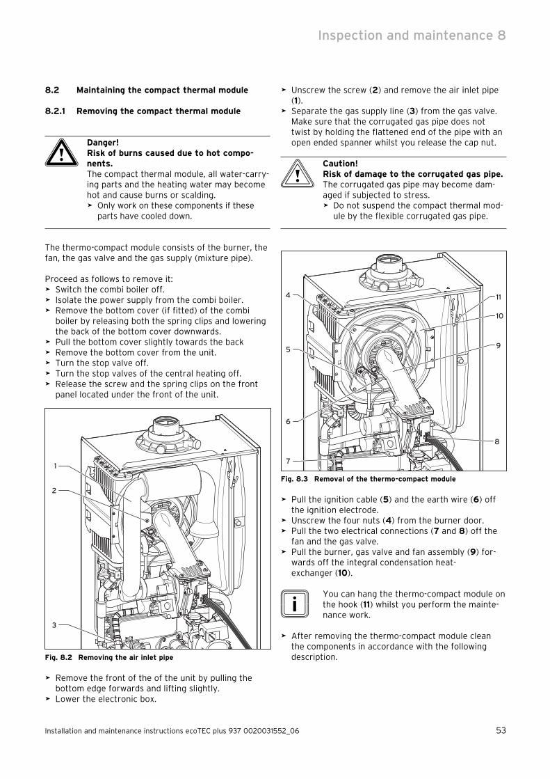
Installation and maintenance instructions ecoTEC plus 937 0020031552_06 53
8.2 Maintaining the compact thermal module
8.2.1 Removing the compact thermal module
a Danger!Risk of burns caused due to hot compo-nents.The compact thermal module, all water-carry-ing parts and the heating water may become hot and cause burns or scalding.
Only work on these components if these parts have cooled down.
The thermo-compact module consists of the burner, the fan, the gas valve and the gas supply (mixture pipe).
Proceed as follows to remove it:Switch the combi boiler off.Isolate the power supply from the combi boiler.Remove the bottom cover (if fitted) of the combi boiler by releasing both the spring clips and lowering the back of the bottom cover downwards.Pull the bottom cover slightly towards the backRemove the bottom cover from the unit.Turn the stop valve off.Turn the stop valves of the central heating off.Release the screw and the spring clips on the front panel located under the front of the unit.
2
3
1
Fig. 8.2 Removing the air inlet pipe
Remove the front of the of the unit by pulling the bottom edge forwards and lifting slightly.Lower the electronic box.
>
>
>
>
>
>
>
>
>
>
>
Unscrew the screw (2) and remove the air inlet pipe (1).Separate the gas supply line (3) from the gas valve. Make sure that the corrugated gas pipe does not twist by holding the flattened end of the pipe with an open ended spanner whilst you release the cap nut.
b Caution!Risk of damage to the corrugated gas pipe.The corrugated gas pipe may become dam-aged if subjected to stress.
Do not suspend the compact thermal mod-ule by the flexible corrugated gas pipe.
10
11
9
8
4
5
6
7
Fig. 8.3 Removal of the thermo-compact module
Pull the ignition cable (5) and the earth wire (6) off the ignition electrode.Unscrew the four nuts (4) from the burner door.Pull the two electrical connections (7 and 8) off the fan and the gas valve.Pull the burner, gas valve and fan assembly (9) for-wards off the integral condensation heat-exchanger (10).
i You can hang the thermo-compact module on
the hook (11) whilst you perform the mainte-nance work.
After removing the thermo-compact module clean the components in accordance with the following description.
>
>
>
>
>
>
>
>
Inspection and maintenance 8

54 Installation and maintenance instructions ecoTEC plus 937 0020031552_06
8.2.2 Cleaning the integral condensation heat exchanger
b Caution!Risk of damage to the electronics.Water may damage the electronics and cause power failures.
Protect the open switch box from spray water.
Dismantle the compact thermo module as described under 8.2.1.
3
4
1
2
Fig. 8.4 Cleaning the heat-exchanger
b Caution!Possible material damage caused by loos-ening or retightening the screws. The primary heat exchanger may become damaged.
You should neither loosen nor tighten the four screws (1).
After removal of the burner and fan assembly you can check the primary heat-exchanger (4).
Remove the loose deposits from the heating coils (3) with a soft brush and a jet of water. Make sure that water is kept away from all electrical components. The water used to clean the primary heat-exchanger runs away through the condensate siphon. Avoid pointing the water jet directly at the insulating sur-face (2) on the back of the heat exchanger.
>
>
>
>
If necessary, the heat-exchanger can be cleaned using ordinary vinegar.
8.2.3 Checking the burner
1
Fig. 8.5 Checking the burner
The burner (1) is maintenance-free and needs no clean-ing.
Check the surface of the burner for damage. If neces-sary, replace the burner.After checking or replacing the burner re-fit the thermo-compact module as described in Section 8.2.4.
8.2.4 Installing the compact thermal module
a Danger!Possible personal injury and material dam-age caused by hot exhaust gases.If you do not renew the seal and the self-lock-ing nuts on the burner door, hot exhaust gases may escape and cause personal injury and material damage.
Replace the seal (1) and the self-locking nuts each time you open the burner door (e.g. when conducting maintenance and service work). Replace the insulating layer on the burner door if it exhibits any sign of damage.
1
Fig. 8.6 Replacing the burner door gasket
Insert a new gasket (1) in the burner door.
>
>
>
>
>
8 Inspection and maintenance

Installation and maintenance instructions ecoTEC plus 937 0020031552_06 55
10
9
8
4
5
7
6
Fig. 8.7 Fitting the thermo-compact module
Insert the compact thermo module (9) in the integral condensation heat exchanger (10).Tighten the four nuts (4) alternately on the left and right until the burner door closes securely and evenly over the surface of the heat exchanger.Re-connect the ignition cable (5) and the earth wire (6) to the ignition electrode.Connect the cable (8) to the fan motor and the cable (7) to the gas fitting.
2
3
1
Fig. 8.8 Connecting the gas supply
Re-connect the gas supply (3) to the gas valve. Use a new seal and ensure it is correctly located. Use the
>
>
>
>
>
flats of the spanner on the flexible gas pipe to hold the gas fittings in position.
11
Fig. 8.9 Checking the gas supply for leaks
Turn on the gas supply and check for leaks. Pay par-ticular attention to fittings (3) and (11).Re-connect the air inlet pipe (1) and make sure that the blue seal is correctly located in the air inlet pipe.
8.3 Cleaning the condensate trap
a Danger!Risk of poisoning due to escaping exhaust gas.Exhaust gases may escape through the empty condensate trap.
Fill the condensate trap with water to pre-vent exhaust gas from escaping through the trap.
1
Fig. 8.10 Cleaning the condensate siphon
Remove the lower section (1) of the water condensate siphon by turning the bayonet connection in a coun-terclockwise direction.Clean the siphon part by flushing it out with water.
>
>
>
>
>
Inspection and maintenance 8

56 Installation and maintenance instructions ecoTEC plus 937 0020031552_06
Fill the lower section with water until about 10 mm below the upper edge.Re-fit the lower section to the condensate siphon.
8.4 Cleaning strainer in cold water supply
There is a strainer in the cold water supply to the combi boiler which must be cleaned during maintenance.
Isolate the unit from the electric mains in the appart-ment as described in 9.2.Close the cold water stop valve on the inlet combina-tion (see Fig. 8.11) and drain the unit from the hot water side.
1
2
3
Fig. 8.11 Cleaning strainer in cold water supply
Release the fitting (1) of the cold water inlet.Release the fitting (3) on the connector (2).
i The fitting (3) is located above the connector
(2) and is not shown in Fig. 8.11.
Remove the connector (2) from the chassis.Flush the connector out under flowing water in the opposite direction to normal flow.Re-fit the connector with the cleaned strainer.Fit the pipe elbows of the shift load storage tank and the cold water feed back in position.Always use new seals.
>
>
>
>
>
>
>
>
>
>
>
8.5 Checking filling pressure of the expansion vessel of the combination boiler
i This check need not be performed every year,
a check every three years is sufficient.
Turn the stop valvess of the central heating off.Release the pressure from the appliance.Remove the valve cover from the expansion vessel.
1
Fig. 8.12 Checking filling pressure of the expansion vessel of
the combination boiler
Check that the internal pressure in the expansion vessel is between 0.75 and 0.9 bar.If the pressure is less than this, the vessel must be pumped up again using an air pump.Refit the valve cover.Re-pressurise the combi boiler and the heating sys-tem.
>
>
>
>
>
>
8 Inspection and maintenance

Installation and maintenance instructions ecoTEC plus 937 0020031552_06 57
8.6 Checking filling pressure of the expansion vessel of the shift load storage tank
i This check need not be performed every year
– a check every three years is sufficient.
Close the stop valves of the hot water system.Release the pressure from the appliance.Release the screw on the top cover of the shift load storage tank and remove the cover.
1
2
Fig. 8.13 Checking filling pressure of the expansion vessel of
the shift load storage tank
The expansion vessel (1) is freely accessible.Unscrew the seal cap (2) from the expansion vessel.Check that the internal pressure of the expansion vessel is approx. 4 bar.If the pressure is less than this, the vessel must be pumped up again using an air pump.Screw the seal cap (2) back onto the expansion ves-sel.Re-fit the cover.Re-pressurise the combi boiler and the hot water sys-tem.
8.7 Re-commissioning the combination boiler
Carry out the electrical safety tests.Switch on the electrical supply.Turn the stop valves of the central heating on.Carry out a function check of the combi boiler as described earlier.Check the gas flow rate as described earlier.Check for water leaks.Re-fit the front case. Make sure that the seal is good.
>
>
>
>
>
>
>
>
>
>
>
>
>
>
>
8.8 Test mode
Always perform the following steps after performing any maintenance work:
Commission the appliance in accordance with the instructions in the relevant operating manual.Check the appliance for gas and water leaks.Check the entire air/flue gas system for leaks and securely fixed.Check ignition and even flame appearance of the burner.Check whether the heating system and the hot water preparation is functioning.Complete the Benchmark gas boiler commissioning checklist in the rear section of these instructions.
Fig. 8.14 Function check
>
>
>
>
>
>
Inspection and maintenance 8

58 Installation and maintenance instructions ecoTEC plus 937 0020031552_06
9 Troubleshooting
9.1 Logical fault finding procedure
Carry out the following checks before the actual trou-bleshooting:
Carry out the tests to check electrical safety (see Section "Preparatory Checks on the Electrical Sys-tem").Check that the external power supply for the combi boiler is switched on and that there is a supply volt-age of 230 V AC between the connections "L" and "N".Check that the gas supply to the combi boiler is switched on.Check that the combi boiler has been properly purged and that there is a supply pressure of 20 mbar the inlet to the boiler. (See Section "Gas Supply".)Check that the heating system is filled with water and that there is a pressure of between 1.0 and 1.5 mbar. Otherwise top up the system and bleed. (See Section "Filling and bleeding the Heating System".)Check that the stop valves in the flow and return lines of the combi boiler are open.Check that the mains switch is set to "ON".Set the temperature of the central heating to "Maxi-mum".Set the temperature of the hot water preparation to "Maximum".Check that all external controllers are switched on and are demanding heat (if no external controllers are fitted, the connections 3 and 4 on the combi boiler terminal must be connected together). Check that the burner anti-cycling time mode on the combi boiler is not active.
>
>
>
>
>
>
>
>
>
>
>
9.1.1 Status codes
The status codes which you can see in the display pro-vide information concerning the current operating sta-tus of the unit.Proceed as follows to display the status codes:
Fig. 9.1 Display of status codes
Press the "i" button.The display shows the status code e.g. “S.04” for the "Burner mode - heating".
The status code display can be de-activated as follows:Press the "i" button or Do not press any button for about 4 minutes.The current heating flow temperature appears in the display again.
>
>
>
>
9 Troubleshooting

Installation and maintenance instructions ecoTEC plus 937 0020031552_06 59
Display Meaning
Heating mode:
S.0 No heat demand
S.1 Fan running
S.2 Pump running
S.3 Ignition
S.4 Burner ignited
S.5 Fan and pump running
S.6 Fan over run
S.7 Pump overrun time
S.8 Anti-cycling mode
Hot water mode (ecoTEC plus 800 models only):
S.10 Hot water request
S.11 Fan running
S.13 Ignition
S.14 Burner ignited
S.15 Fan and pump running
S.16 Fan over-run
S.17 Pump over-run
Warm start mode/hot water storage tank charging:
S.20 Pump running
S.21 Fan running
S.23 Ignition
S.24 Burner ignited
S.25 Fan and water pump running
S.26 Fan over-run
S.27 Pump over-run time
S.28 Anti-cycling mode
All boilers:
S.30No heat demand from external controllers (terminal 3-4 open)
S.31Thermostat knob of central heating switched off or no heat demand from an eBUS controller
S.32Heat exchanger antifreeze active, as fan speed varia-tion is too high. Appliance is within the waiting time of the operation block function
S.34 Antifrost mode active
S.36No heat demand from low voltage regulators (termi-nal 7-8-9)
S.41 Water pressure >2.9 bar
S.42Feedback from accessories module or defective con-densate pump blocks the burner operation
S.53Appliance is within the waiting period of the modula-tion block/operation block function due to water shortage (flow-return spread too large)
S.54Appliance is within the waiting period of the opera-tion block function due to water shortage (tempera-ture gradient)
S.96Return flow sensor test, heat demands (hot water or heating) are blocked
S.97Water pressure sensor test, heat demands (hot water or heating) are blocked
S.98Flow/return flow sensor test, heat demands (hot water or heating) are blocked
Table 9.1 Status codes (continuation see next page)
9.1.2 Diagnostic codes
In the diagnostic mode, you can change certain parame-ters or display more information.The diagnostic information is divided into two diagnostic levels. Access to the second diagnostic level can only be permitted after entering a password.
b Caution!Possible material damage caused by improper handling.Improper settings in the 2nd diagnostic level may cause damage to the heating system.
The 2nd diagnostic level should only be accessed if you are a recognised special-ised technician with Health and Safety Executive approval.
First diagnostic levelPress the "i“ and "+“ buttons simultaneously.
The display shows "d.00“.Use the buttons "+“ or "–“ to move to the desired diagnostic number of the first diagnostic level (see the Table 9.2).Press the "i" button.
The associated diagnostic information is shown in the display.
If necessary you can change the value with the but-tons "+“ or "–“ (display flashing).Save the new value by holding down the "i“ button for approx. 5 seconds until the display no longer flashes.
You can end the diagnostic mode as follows:Press the "i“ and "+“ buttons simultaneously. orDo not press any button for about 4 minutes.
The current heating flow temperature appears in the display again.
>
>
>
>
>
>
>
>
Troubleshooting 9

60 Installation and maintenance instructions ecoTEC plus 937 0020031552_06
Display Meaning Displayed value/settable value
d.0 Heating partial loadAdjustable heating partial load in kW (factory setting: max. out-put)
d.1 Water pump over run time for heating mode 2 - 60 minutes (factory setting: 5 minutes)
d.2 Max. anti cycle time heating at 20°C flow temperature 2 - 60 minutes (factory setting: 20 minutes)
d.3 Measured value of the domestic hot water temperature in °C
d.4 Measured value for the warmstart sensor in °C
d.5Flow temperature target value or return temperature tar-get value, if return flow regulation selected
in °C, max. of the value set in d.71limited by an eBUS controller, if fitted)
d.6 Hot water target temperature in °C, 35 to 65 °C
d.7 Warm start target temperature in °C, 40 to 65 °C
d.8 Heat demand of external controllers (terminal 3-4)0=opened (no heating requirement)1=closed (heating requirement);
d.9Flow target temperature from external analogue regulator to terminal 7-8-9/eBus
in °C, minimum from ext. eBus target value and target value terminal 7
d.10 Status internal heating pump 1, 2 = on, 0 = off
d.11 Status external heating pump (via accessory module) 1 to 100 = on, 0 = off
d.12 Cylinder charging pump (via accessories module) 1 to 100 = on, 0 = off
d.13External hot water circulation pump (via accessory mod-ule)
1 to 100 = on, 0 = off
d.22 Hot water demand 1 = on, 0 = off
d.23 Summer /winter function 1 = Winter, 0 = Summer
d.25 Hot water activation via eBUS controller 1 = yes, 0 = no
d.30 Control signal for both gas valves 1 = on, 0 = off
d.33 Fan speed target value in upm/10
d.34 Fan speed actual value in upm/10
d.35 Internal diverter valve position 0 = heating; 100 = hot water; 40 = mid-position
d.36 Hot water flow sensor in l/min
d.40 Flow temperature actual value in °C
d.41 Return flow temperature actual value in °C
d.44 digitalised ionisation voltage Display range 0 to 102, >80 no flame, <40 good flame display
d.47External temperature (only on weather-compensated Vail-lant controllers)
actual value in °C
d.67 Remaining burner anti-cycling time in minutes
d.76 Unit variants (device specific number) 00 to 99
d.90 Status of the digital controller 1 = identified, 0 = unidentified (eBUS Address <=10)
d.91DCF status with connected external probe with DCF77 receiver (not available in the UK)
0 = no reception, 1 = reception, 2 = synchronised, 3 = valid
d.92 Module recognition shift load storage tank
Setting range:0 = not recognised1 = no communication via PE-BUS; Module recognised earlier2 = Communication OKSetting = 0: Unregister shift load storage tank from combi
boiler (if shift load storage tank is to be de-installed, set d.92 = 0)
d.97 Activation of the second diagnostic level Password: 17
Table 9.2 Diagnostic codes of the first diagnosis level
9 Troubleshooting

Installation and maintenance instructions ecoTEC plus 937 0020031552_06 61
Second diagnostic levelAs described above in the first diagnostic level, scroll through to the diagnosis number d.97.Change the displayed value to 17 (Password) and push the button "i".
You are now in the second diagnostic level where all information from the first diagnostic level (see Table 9.2) and the second diagnostic level (see Table 9.3) is displayed.
Display Meaning Displayed value/settable value
d.17 Heating flow/return regulation changeover 0 = flow, 1 = return (factory setting: 0)
d.18 Pump mode (return flow) 0 = overrun, 1 = continuous, 2 = winter (Factory setting: 0)
d.19 Operating modes of the two-speed heating pump 0 = Pre-ignition speed 1, Hot water or heating speed 2, overrun speed 1
1 = Pre-ignition speed 1, hot water speed 2, heating speed 1, overrrun speed 1
2 = Like 1 but speed in heating mode dependant on heating part load d.0 (if d.0 is below 60 % of full load, then pump speed 1, otherwise speed 2); Factory setting 2)
3 = Always speed 2
d.20 Maximum set value for external cylinder target tempera-ture (system boilers only)
Setting range: 50 °C to 70 °C (Factory setting 65 °C)
d.27 Switching relay 1 on the accessories module 1 = Circulation pump (factory setting)2 = Ext. Pump3 = External cylinder charging pump4 = Flue gas flap/extractor hood5 = External gas valve6 = External error message
d.28 Switching relay 2 on the accessories module 1 = Circulation pump2 = Ext. pump (factory setting)3 = External cylinder charging pump4 = Flue gas flap/extractor hood5 = External gas valve6 = External error message
d.50 Offset for minimum fan speed in upm/10, adjustment range: 0 to 300
d.51 Offset for maximum fan speed in upm/10, adjustment range: -99 to 0
d.58 Activation solar pre-heat function Setting range: 0 to 30 = solar post-heating deactivated (factory setting)3 = Activation hot water target value min = 60 °C for solar pre-
heat
d.60 Number of safety temperature limiting switch-offs Quantity
d.61 Number of unsuccessful ignitions Number of successful ignitions in the last attempt
d.64 Average ignition duration in seconds
d.65 maximum ignition duration in seconds
d.68 Successful ignitions at the first attempt Quantity
d.69 Successful ignitions at the second attempt Quantity
d.70 Setting the diverter valve position 0 = Normal mode (factory setting)1 = mid-position2 = Permanent heating position
d.71 Maximum flow temperature knob setting Adjustment range in °C 40 to 85 (Factory setting: 75)
Table 9.3 Diagnostic codes in the second level
>
>
Scroll and change values and exit diagnosis mode as described in the first diagnosis level.
i If you push the buttons "i" and "+" again
within 4 minutes after leaving the second diagnosis level you will go directly to the sec-ond diagnosis level without having to enter the password again.
Troubleshooting 9

62 Installation and maintenance instructions ecoTEC plus 937 0020031552_06
Display Meaning Displayed value/settable value
d.72 Pump overrun time after warm start or shift load storage tank charging
Setting range in seconds: 0, 10, 20 to 600Factory setting: 80
d.73 Offset for warm start target temperature Setting range: -15 K to +5 K (Factory setting: 0K)
d.74 Legionella protection shift load storage tank Setting range:0 = deactivated1 = activated (Factory setting)
d.75 Maximum charging duration for an external cylinder with-out its own control (system boilers only)
Adjustment range in min: 20, 21, 22 to 90 (Factory setting: 45)
d.77 Part load of the external cylinder (limit for charging capacity of the external cylinder, system boilers only)
Adjustment range in kW: appliance specificFactory setting: max. output
d.78 Limit for charging temperature of the external cylinder (target flow temperature in storage tank mode, system boilers only)
Adjustment range in °C 55 to 85 (Factory setting: 80)
d.80 Operating hours heating in h
d.81 Operating hours hot water generation in h
d.82 Operating cycles in heating mode number/1001) (3 equals 300)
d.83 Cycles in hot water operation number/1001) (3 equals 300)
d.84 Maintenance indicator: Number of hours until the next maintenance
Setting range: 0 to 3000h and „-“ for deactivatedFactory setting: „-“ (300 corresponds to 3000h)
d.88 switching on threshold for recognizing water tapping (only VCW)
0 = 1,5 l/min and no delay, 1 = 3,7 l/min and 2s delay
d.92 Module recognition shift load storage tank Setting range:0 = not recognised1 = no communication via PE-BUS; Module recognised earlier2 = Communication OKSetting = 0: Unregister shift load storage tank from combi boiler (if shift load storage tank is to be de-installed, set d.92 = 0)
d.93 DSN appliance variant setting Setting range: 0 to 99
d.96 Factory reset 1 = Resetting adjustable parameters to factory setting
1) In the diagnostic codes 80 to 83 5 digit figure values are stored. When selecting e.g. d.80 only the first two digits of the figure value are displayed (e.g.10). By pressing the „i“ key, the display switches over to the last three figures (e.g. 947). The operating hours coun-ter of the heating in this case would be 10947 h. Pressing the „i“ again causes the display to switch back to the diagnosis point that was called up.
Table 9.3 Diagnosis codes of the second diagnosis level (con-
tinued)
9.1.3 Error codes
Fault codes take priority over all other display functions in the event of a system fault occurring.If many errors occur simultaneously, the relevant error codes are displayed alternately for approx. 2 seconds each.
9.1.4 Fault memory
The fault memory of the unit stores the information concerning the last ten errors.
Press the "i“ and „-“ buttons simultaneously.Scroll backwards with button "+“ through the list of stored errors.
You can exit the error memory display as follows:Push the button "i“under the display, orDo not press any button for about 4 minutes. The dis-play then switches back to the display of current flow temperature.
>
>
>
>
9 Troubleshooting

Installation and maintenance instructions ecoTEC plus 937 0020031552_06 63
Code Meaning Cause
F.0 Flow NTC open circuitNTC faulty, NTC cable faulty, faulty plug connection on NTC, faulty plug connection on the electronics
F.01 Return NTC open circuitNTC faulty, NTC cable faulty, faulty plug connection on NTC, faulty plug connection on the electronics
F.02Shift load storage tank charging (NTC) open circuit,only in combination with F.91
NTC faulty, NTC cable faulty, faulty plug connection on NTC, faulty plug connection on the electronics
F.03Shift load storage tank temperature (NTC) open circuit,only in combination with F.91
NTC faulty, NTC cable faulty, faulty plug connection on NTC, faulty plug connection on the electronics
F.10 Flow NTC short circuit NTC faulty, NTC plug short-circuited to casing
F.11 Return NTC short circuit NTC faulty, NTC plug short-circuited to casing
F.12Short circuit in storage tank charging sensor (NTC)only in combination with F.91
Sensor plug has mass short to the casing, short-circuit in wiring loom, sensor faulty
F.13Short circuit storage tank temperature sensor (NTC)only in combination with F.91
Sensor plug has mass short to the casing, short-circuit in wiring loom, sensor faulty
F.20 Safety temperature limiter by NTC activatedFlow probe not connected thermally correct or defective, appli-ance does not shut down
F.22 Dry fireToo little water in the appliance, water pressure sensor defec-tive, cable to pump or water pressure sensor defective, pump seized or defective, pump output too low
F.23Water shortage, temperature spread between flow and return NTC too large
Pump seized or defective, pump output too low, flow and return sensor swapped over
F.24 Water shortage, temperature rise too quickPump seized, low output from the pump, air in appliance, system pressure too low
F.25 Compact thermal module wiring harness open circuit Wiring harness thermo-compact module faulty
F.27 Incorrect sensing of flame Flame monitor faulty
F.28 Unit will not start: Attempts to ignite during start failed
Faults in the gas supply such as:- Gas meter or gas pressure regulator- Air in gas- Gas flow pressure too lowFaults in the gas valve, wrong gas setting, igniter (ignition trans-former, ignition cable, ignition plug) defective, ionisation current stopped (cable, electrode), faulty earthing in appliance, electron-ics defective
F.29Flame goes off during operation and subsequent ignition attempts failed
Gas supply temporarily interrupted, defective earthing of the unit
F.32 Speed deviation FanFans seized, plug not inserted correctly on fan, hall sensor defec-tive, fault in cable harness, electronics defective
F.49 eBUS undervoltageShort-circuit on eBUS input, eBUS overload or two power sup-plies with different polarities on the eBUS
F.61 Gas valve control faultyShort circuit/earth(ground) leak in cable harness to gas valve, gas valve assembly defective (earth/ground leak from solenoid), electronics fault.
F.62 Switch-off delay of the gas valve faulty gas valve leaking, electronics defective
F.63 EEPROM error Defective electronics
F.64 Electronics/NTC faultShort-circuit in flow or return NTC or electronics defective/ air in gas
F.65 Electronics temperature too high Electronics too hot due to external effect, electronics defective
F.67 Flame monitor input signal is outside the limits (0 or 5 V) electronics defective
F.70No valid appliance variant for display and/or electronics (DSN number invalid)
Spare parts error: Display and electronics changed at the same time appliance variant not re-set
F.71 Flow NTC reports constant value Flow NTC is defective
F.72 Flow and/or return NTC fault Feed and/or return NTC is faulty (tolerance too great)
F.73Signal water pressure sensor in the wrong range (too low)
Line to water pressure sensor is interrupted or has a short-cir-cuit to 0 V or water pressure sensor faulty
Table 9.4 Error codes
Troubleshooting 9

64 Installation and maintenance instructions ecoTEC plus 937 0020031552_06
Code Meaning Cause
F.74Signal water pressure sensor in the wrong range (too high)
Harness to water pressure sensor has a short-circuit at 5 V / 24 V or internal fault in water pressure sensor
F.75No sudden change in pressure was detected on turning on the pump
Water pressure sensor and/or pump faulty (pump seized - check system water for contamination)Air in heating system, automatic air vent system faultyToo little water in the unit; check adjustable bypass;Connect expansion vessel in return;
F.76Overheating protection on primary heat-exchanger activated
Cable or cable connection of fuse in the primary heat exchanger defective, replace primary heat exchanger
F.77Condensate pump or return signal from accessory module blocks heating
Condensate pump faulty or return signal from the exhaust gas flap has activated
F.78 Incorrect configuration of accessories Control Center VR 65 connected to combination boiler
F.80Interruption or short-circuit of SWT inlet sensor only in conjunction with F.91
NTC defective, NTC cable defective, defective plug connection at NTC, defective plug connection at APC electronics Plug at sensor has short-circuited to housing, short-circuit in cable harness, sensor defective
F.81 APC loadpump fault connected to F.91
Inadequate heat transfer between the heater and storage tank.– Check storage tank charge sensor and storage tank sensor– Air in the APC pump– Check pump wiring harness– Secondary heat exchanger blocked– Priority changeover valve defective– Pump defective– Plate-type heat exchanger scaled
F.90Communication with shift load storage tank module interrupted
Check wiring harness from combi boiler to shift load storage tank (PE Bus). If combi boiler is to be operated without shift load storage tank, set d.92 = 0
F.91 Sensor error on shift load storage tank module (NTC)NTC faulty, NTC cable faulty, faulty plug connection on NTC, faulty plug connection on the electronics
con No communication with the printed circuit boardCommunication fault between the display and the printed circuit board in the electronics box
Table 9.4 Error codes (continued)
9 Troubleshooting

Installation and maintenance instructions ecoTEC plus 937 0020031552_06 65
9.2 Test programmes
Display Meaning
P.0
Bleeding test program. The heating circuit and the hot water circuit are bled via the automatic air vent (the cap of the automatic air vent must be released two turns).
P.1Test programme where the appliance is operated in full load after successful ignition.
P.2Test program where the appliance is operated with minimum gas volume (ignition gas volume) after successful ignition
P.3 not available
P.4 not available
P.5
Test programme for checking the safety tempe-rature limitation: The unit is heated by avoidance of the regular switch-off by the feed regulator until a temperature of 97 °C is reached.
P.6Filling programme: The diverter valve moves to the centre position.
Table 9.5 Test programmes
Special functions can be triggered in the appliance by activating various test programs.These programmes are listed in detail in Table 8.5.
The test programmes “P.0” to “P.6” will be started when " Power ON“ is turned on and the "+“ button is pressed for 5 seconds simultaneously.The display shows "P.0“.Press the "+" key to start counting the test pro-gramme number upwards.Press the "i“ to operate the appliance now and to start the test programme.To de-activate the setting mode, simultaneously push the buttons "i“ and "+“. You can also end the test programmes by not pushing any button for a 15 minute period.
9.3 Resetting the parameters to factory settings
Besides the option to reset individual parameters manually to the factory settings specified in Tables 9.2 and 9.3, you can also reset all parameters simultane-ously.
In the second diagnostic level, under the diagnostic point "d.96" change the value to 1 (see Section 9.1.2).
The parameters of all adjustable diagnosis points now correspond to the factory settings.
>
>
>
>
>
10 Replacing components
The tasks listed below may only be undertaken by a competent engineer approved at the time by the Health and Safety Executive.
Only use genuine spare parts for repairs.Check that the parts are correctly fitted and that the original location and alignment is maintained.
10.1 Safety instructions
Each time the components are replaced, you must com-ply with the safety instructions below for your own safety and to avoid damage to the appliance.
Take the appliance out of operation.
e Danger!Risk of fatal electric shock through contact with live connections.The supply terminals of the appliance are under voltage even if the mains switch is off.
Disconnect the appliance from the mains supply by removing the power plug or de-energise the appliance using a separator with a contact opening of at least 3 mm (e.g. fuses or circuit breakers).
Close the stop valves in the gas supply and in the heating flow and return pipes.Close the cold water inlet stop valve (only on combi boilers).Drain the unit if you wish to replace water-conducting components in the unit.Make sure that no water drips on live electrical com-ponents (e.g. electronic box etc.).Use only new gaskets and O-rings.Check the system for gas leaks after completion of the work. Carry out a function test (see Section 7.8).After all maintenance work and after replacing elec-trical components check the earthing, polarity and earth resistance using a multi-meter.
>
>
>
>
>
>
>
>
>
>
>
Troubleshooting 9Replacing components 10

66 Installation and maintenance instructions ecoTEC plus 937 0020031552_06
10.2 Replacing the burner
a Danger!Risk of personal injury and/or material damage as a result of non-compliance with the safety instructions.
Before replacing the component, comply with the safety instructions in Chapter 10.1.
Dismantle the compact thermo module as described under 8.2.1.
1
Fig. 10.1 Replacing the burner
Release the 4 screws (1) on burner, and remove the burner.Mount the new burner with a new gasket. The notch in the burner must be aligned with the sight glass of the burner.Fit the compact thermo module as described under 8.2.4.Fit a new burner door seal kit.After completion of the work check the system for gas leaks and carry out a function test (see Sec-tion 8.8).
i A new burner door seal kit must be fitted
every time the burner door is removed.
>
>
>
>
>
>
>
10.3 Replacing the fan or the gas valve
a Danger!Risk of personal injury and/or material damage as a result of non-compliance with the safety instructions.
Before replacing the component, comply with the safety instructions in Chapter 10.1.
Switch the combi boiler off.Isolate the electrical supply from the combi boiler.Remove the air intake pipe (Fig. 8.1, Pos. 3).Loosen the gas supply pipe on the gas valve (Fig. 8.2, Pos. 3).
1
3
2
4
Fig. 10.2 Removing the fan with gas fitting
Pull the plug (4) out of the gas valve.Pull the plug (3) out of the fan.Unscrew the three screws (2) out of the thermo-com-pact module (1).Remove the complete component group "gas valve/fan".
5
Fig. 10.3 Gas valve/fan screwed joint
>
>
>
>
>
>
>
>
>
10 Replacing components

Installation and maintenance instructions ecoTEC plus 937 0020031552_06 67
Release both fixing screws (5) on the gas valve and remove the fan from the gas valve.Replace the faulty component.
b Caution!Possible material damage caused by improper installation.The gas valve and the fan may be damaged as a result of incorrect installation.
Fit the gas valve and the fan in the same position as before.
Screw the fan onto the gas valve. Use new seals.Re-install the complete "gas valve/fan" unit in reverse sequence.After completion of the work check the system for gas leaks and carry out a function test (see Section 8.8).
10.4 Replacing the expansion vessel
a Danger!Risk of personal injury and/or material damage as a result of non-compliance with the safety instructions.
Before replacing the component, comply with the safety instructions in Chapter 10.1.
Disconnect the appliance from the mains as described in Chapter 10.1, and close the gas isolator valve in the gas supply pipe.Close the stop valves in the flow and return pipes and drain the water out of the combi boiler.
>
>
>
>
>
>
>
>
>
1
2
3
4
Fig. 10.4 Replacing the expansion vessel
Unscrew the nuts (4) from the water pipe on the underside of the expansion vessel.Unscrew the two screws (1) in the retaining plate (2) and remove the retaining plate.Pull out the expansion tank (3) forwards.Guide the new expansion tank back into the appli-ance.Re-connect the new expansion tank using a new gas-ket.Re-fit the retaining plate.Check the pressure of the expansion tank (minimum pressure 0.75 bar).If required, match the pressure to the static head of the heating system.Fill and bleed the combi boiler.After completion of the work check the system for gas leaks and carry out a function test (see Section 8.8).
>
>
>
>
>
>
>
>
>
Replacing components 10

68 Installation and maintenance instructions ecoTEC plus 937 0020031552_06
10.5 Replacing the primary heat exchanger
a Danger!Risk of personal injury and/or material damage as a result of non-compliance with the safety instructions.
Before replacing the component, comply with the safety instructions in Chapter 10.1.
Disconnect the appliance from the mains as described in Chapter 10.1, and close the gas isolator valve in the gas supply pipe.Close the stop valves in the flow and return pipes and drain the water out of the combi boiler.Remove the compact thermo module as described under 8.2.1.Remove the expansion tank as described under 10.4.Pull off the condensate pipe which runs from the pri-mary heat-exchanger to the siphon.
1
2
4
3
Fig. 10.5 Replacing the primary heat exchanger
Remove the clamps (1) and (2) and pull off the flow and return hoses from the primary heat-exchanger.Unscrew the four screws (3) on the holder of the pri-mary heat-exchanger.
>
>
>
>
>
>
>
>
3
2
1
Fig. 10.6 Holder for the primary heat-exchanger
Pull the plug connection (2) of the thermal fuse off the primary heat-exchanger.Unscrew the three screws (3) on the holder of the primary heat-exchanger.Turn the holder to the side around the rivet (1), pull the primary heat exchanger downwards to the right and remove it from the appliance.Mount the new primary heat exchanger.Fit a new burner door seal kit.Fit the burner module.Continue to replace in the reverse order.
i A new burner door seal kit must be fitted
every time the burner door is removed.
>
>
>
>
>
>
>
10 Replacing components

Installation and maintenance instructions ecoTEC plus 937 0020031552_06 69
b Caution!Possible material damage caused by loos-ening or retightening the screws.The primary heat exchanger may become damaged.
You must not loosen or tighten the four screws (fig. 8.4, 1).
b Caution!Possible material damage caused by lubri-cating the seals.Mineral oil-based lubricants may damage the seals. The seals should therefore not be lubri-cated.
Only use water or commercially available soft soap, if necessary, to assist with installation.Insert the flow and return connection into the primary heat exchanger as far as pos-sible and make sure the brackets on the flow and return connection are seated properly.
Filling and vent the combi boiler as required.After completion of the work check the system for gas leaks and carry out a function test (see Section 8.8).
10.6 Replacing the expansion vessel of the shift load storage tank
a Danger!Risk of personal injury and/or material damage as a result of non-compliance with the safety instructions.
Before replacing the component, comply with the safety instructions in Chapter 10.1.
Disconnect the appliance from the mains as described in Section 10.1, and close the gas isolator valve in the gas supply pipe.Close the cold water inlet stop valve.Open a hot water tap in order to release the pressure on the water circuit. Then close the tap again.Remove the screw on the cover of the shift load stor-age tank.Remove the cover.
>
>
>
>
>
>
>
>
>
>
>
1
2
Fig. 10.7 Replacing the expansion vessel of the shift load stor-
age tank
The expansion vessel (1) is freely accessible.Release the nuts (2) on the expansion tank.Pull the expansion tank (1) off the pipe fitting and remove it from the EPS trough.Insert the new expansion tank in the EPS trough.Re-connect the new expansion tank. Use a new gas-ket:Check the pressure of the expansion tank (minimum pressure 4 bar).Filling and vent the combi boiler and the shift load storage tank.After completion of the work check the system for gas leaks and carry out a function test (see Section 8.8).
10.7 Replacing the storage tank pump of the shift load storage tank
a Danger!Risk of personal injury and/or material damage as a result of non-compliance with the safety instructions.
Before replacing the component, comply with the safety instructions in Chapter 10.1.
Isolate the unit from the mains as described in Sec-tion 10.1.Close the gas isolator valve in the gas supply pipe.Close the stop valves in the hot water system and drain the water out of the combi boiler and the shift load storage tank.
>
>
>
>
>
>
>
>
>
>
>
>
Replacing components 10

70 Installation and maintenance instructions ecoTEC plus 937 0020031552_06
2
1
5
4
3
6
Fig. 10.8 Replacing storage tank pump
Remove the discharge pipe (1) of the heating pres-sure relief.Lower the electronics box as described in Sec-tion 5.19.2.Unclip the back cover of the electronics box and swing the cover upwards to reveal the connections.Pull the plug X12 off the electronic printed circuit board.Pull the free end of the line carefully through the entry grommets on the combi boiler and on the shift load storage tank.Release the sensor wire of the pump from the wiring harness by pulling the plug off the wiring harness.Unscrew the sheet metal bracket (6) from the chas-sis.Release the fitting (2) on the connector pipe (3).Release the spring clamp (5) on the storage tank charging pump casing (4).Support the storage tank charging pump with your other hand to prevent it from falling out of the chassis.Pull the storage tank charging pump out of the chas-sis downwards.Fit the pipe bracket to the new storage tank charging pump using new gaskets.Fit the new storage tank charging pump in reverse order and use new gaskets.Connect the electrical wires of the pump in reverse sequence. Check for correct routing of the lines.Re-fit the discharge pipe (1) and use new gaskets.Filling and vent the combi boiler and the shift load storage tank.
>
>
>
>
>
>
>
>
>
>
>
>
>
>
>
After completion of the work check the system for gas leaks and carry out a function test (see Section 8.8).
10.8 Replacing the aqua sensor
a Danger!Risk of personal injury and/or material damage as a result of non-compliance with the safety instructions.
Before replacing the component, comply with the safety instructions in Chapter 10.1.
Isolate the unit from the mains as described in Sec-tion 10.1.Close the gas isolator valve in the gas supply pipe.Close the stop valves in the hot water system and drain the water out of the combi boiler and the shift load storage tank.
3 2
5
4
1
Fig. 10.9 Replacing the aqua sensor
Remove the discharge pipe (1) of the heating pres-sure relief.Separate the electrical wire of the aqua sensor from the wiring harness by pulling off the plug from the wiring harness.Release the fitting (2) and (3) on the elbows (4) and (5).Turn the Aqua-Sensor slightly to the side and pull the Aqua-Sensor downwards out of the chassis.Remove the pipe elbow from the Aqua-Sensor.
>
>
>
>
>
>
>
>
>
>
10 Replacing components

Installation and maintenance instructions ecoTEC plus 937 0020031552_06 71
Replacing components 10
Fit the pipe elbow onto the new Aqua-Sensor and use new gaskets.Mount the new Aqua-Sensor in reverse order and replace the seals.Connect the line plug of the Aqua-Sensors with the wiring harness.Re-fit the discharge pipe (1) and use new gaskets.Filling and vent the combi boiler and the shift load storage tank.After completion of the work check the system for water leaks and carry out a function test (see Sec-tion 8.8).
10.9 Replacing the electronics on the shift load storage tank
a Danger!Risk of personal injury and/or material damage as a result of non-compliance with the safety instructions.
Before replacing the component, comply with the safety instructions in Chapter 10.1.
Isolate the unit from the mains as described in Sec-tion 10.1.Close the gas isolator valve in the gas supply pipe.Comply with the assembly and installation manuals provided with the spare parts.Remove the screw on the top cover of the shift load storage tank and remove the cover.
1
Fig. 10.10 Replacing electronics
Pull the electronics (1) out of the location slot.Pull off the plug connector from the wiring harness.Fit the new electronics in reverse order.Start up the appliance.
Check the correct setting of the unit variants (DSN) as follows:
Enter the 2nd diagnostic level of the combi boiler.Set the equipment-specific DSN value (parameter "d.93“) in accordance with Table 10.1.
>
>
>
>
>
>
>
>
>
>
>
>
>
>
>
>
>
Appliance type DSN
ecoTEC plus 937 8
Table 10.1 DSN Setting Values
Exit the diagnostic mode.
The combi boiler ecoTEC plus 937 is ready for opera-tion.
10.10 Replacing the electronics and display on the combi-heater
a Danger!Risk of personal injury and/or material damage as a result of non-compliance with the safety instructions.
Before replacing the component, comply with the safety instructions in Chapter 10.1.
Comply with the assembly and installation manuals provided with the spare parts.
Replacing the display or the electronicsIf you are only replacing one of the two components the parameter settings take place automatically. When switching the unit on the new component automatically takes the pre-set parameters from the components which have not been changed.
Replacing the display or the electronicsWhen replacing both components, after being turned on, the appliance goes to fault and displays the error mes-sage F.70.
In the second diagnostic level, under the diagnostic point "d.93" enter the number of appliance variant according to Table 9.1 (see Chapter 9.9).
The electronics is now set to the appliance type and the parameters of all adjustable diagnostic points corre-spond to the factory settings.
>
>
>
>
72 Installation and maintenance instructions ecoTEC plus 937 0020031552_06
11 Recycling and disposal
Both the gas fired boiler and its transport packaging consist mainly of recyclable raw materials.
ApplianceDo not dispose of your Vaillant ecoTEC gas fired wall hung boiler appliance or any of its accessories with normal household waste. Ensure that old appliances and any existing
accessories are disposed of properly.
PackagingThe specialist company that installed the appliance is responsible for disposing of the transport packaging.
i Please observe the applicable national legal
regulations.
12 Vaillant service
To ensure regular servicing, it is strongly recommended that arrangements are made for a Maintenance Agree-ment. Please contact Vaillant Service Solutions (0870 6060 777) for further details.
11 Recycling and disposal12 Vaillant service

Installation and maintenance instructions ecoTEC plus 937 0020031552_06 73
EC declaration of conformity
EC declaration of conformity

74 Installation and maintenance instructions ecoTEC plus 937 0020031552_06

Installation and maintenance instructions ecoTEC plus 937 0020031552_06 75
Installation,Commissioning and
Service Record
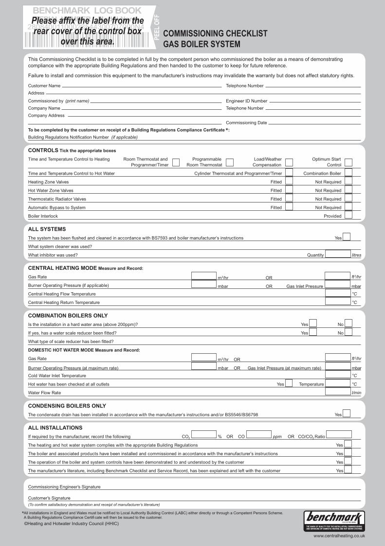
76 Installation and maintenance instructions ecoTEC plus 937 0020031552_06

Installation and maintenance instructions ecoTEC plus 937 0020031552_06 77


00
20
03
155
2_0
6 G
BIE
1
02
010
—
Su
bje
ct t
o a
lter
ati
on
s