ecosystem led driver overview - lutron electronics · 25 w max. d d voltage driver operation range:...
TRANSCRIPT

® Specif icat ion Submittal page
Job Name:
Job Number:
Model Numbers:
LED Dimming Driver EcoSystem® LED Driver Architectural Dimming
369341a 1 12.02.11
EcoSystem® LED Driver Overview
EcoSystem® LED Driver is a high-performance LED driver that provides smooth, continuous 1% dimming for virtually any LED fixture, whether it requires constant current or constant voltage.
Features
•Continuous,flicker-freedimmingfrom100%to1%•EcoSystem®digitallinkcontrol,compatiblewith
EcoSystem® Energi Savr NodeTM modules and Quantum® systems
•CanbeusedinconjunctionwithEcoSystem® compatibleballastsanddevices
•ProtectedfrommiswiresofinputpowertoEcoSystem® control inputs
•CEandENEC•Independentcontrolgearwithintegralstrainrelief•SELVoutput•Aratedlifetimeof50000hours@tc=75°C•Constantcurrentdriverswithstabilizedoutputcurrentfrom0,20Ato1,05A
–ConstantCurrentReduction(CCR)dimmingorPulseWidthModulation(PWM)dimming.SeeApplicationNote#360fordetails.
•Constantvoltagedriverswithstabilizedoutputvoltagefrom8Vto40V
–PulseWidthModulation(PWM)dimming•100%performancetestedatfactory•100%burnedinatfactory
EcoSystem® LED Driver
89,7mmWx31,8mmHx154,7mmL
1% Dimming LED Driver
WARNING: Shock hazard. May result in serious injuryor death. Disconnect power before servicing or installing.
Warranty void if unit is opened.
Coopersburg, PA 18036 USA
EcoSystem® LED
ta= 40 °CPout: 25 W Max
Vin:Iin:
tc=freq:
Vout:Iout:
220-240 V~0.140 A
75 °C50 / 60 Hz
43 V- Max1.05 A-
0 27557 00144 1
LDEA2E1CPA-HA105
λ = 0.95
��TO
EcoSytem®
BUS
+44 (0)20.7680.4481
E1
E2
LIVE
0,5 - 1,5 mm²
0,5 - 2,5 mm²
Max. lead length
8 mm
NEUTRAL
3,0 m (10 ft)
tc
DIG
ITAL B
US
E1
E2
INP
UT
L
SE
LVO
UTP
UT
+V-V
EcoSystem®
LEDDriver
0,5 - 2,5 mm²
INP
UT
N
0,5 - 2,5 mm²
LED load ONLY
Copper wire only

® Specif icat ion Submittal page
Job Name:
Job Number:
Model Numbers:
LED Dimming Driver EcoSystem® LED Driver Architectural Dimming
369341a 2 12.02.11
Specifications
Performance
•DimmingRange:100%to1%•OperatingVoltage:220–240V~ at50/60Hz•Patentedthermalfoldbackprotection•LEDsturnontoanydimmedlevelwithoutgoing tofullbrightness
•Nonvolatilememoryrestoresalldriversettingsafterpower failure
•PowerFactor:λ>0,95at25W•TotalHarmonicDistortion(THD):<20%at25W•InrushCurrent:<2A•InrushCurrentLimitingCircuitry:eliminatescircuitbreakertripping,switcharcingandrelayfailure
•Opencircuitprotected•Shortcircuitprotected•Lifetime:50000hours@tc=75°C ConsultLutronforderatinginformation
•Efficiency:80%atmaxpower(25W)•Turn-ontime:≤1second
Environmental
•SoundRating:Inaudibleina27dBambient•RelativeHumidity:maximum90%non-condensing•MinimumOperatingAmbientTemperature:ta=0°C•MaximumCalibrationPoint:tc=75°C•MaximumOperatingAmbientTemperature:ta=40°C ConsultLutronforderatinginformation
Standards
•CEandENEC –Safety:IEC/EN61347-2-13 –Emissions:CISPR15/EN55015,IEC61000-3-2,-3-3 –Immunity:IEC/EN61547,IEC/EN61000-4-2,-4-3,
-4-4,-4-6,-4-11 –Performance:IEC/EN62384•RoHS2006Compliant•IEC60529,IP20Rating•Lutron®QualitySystemsregisteredtoISO9001.2008
Driver Wiring & Mounting
•WiringMeans:Daisychaincapableterminalsforinput – input Screw terminals: –1or2cables,2core0,5mm2to2,5mm2 –DaisyChainMaximum:8units –RecommendedWireTypes:H03VV-F,H03VVH2-F,
H05VV-F,andH05VVH2-F – ecoSystem® terminals: –1or2cables,2core0,5mm2to1,5mm2 –RecommendedWireTypes:H03VV-F,
H03VVH2-F,H05VV-F,andH05VVH2-F – output Screw terminals: –1cable,2core0,5mm2to2,5mm2
–RecommendedWireTypes:H03VV-F,H03VVH2-F,H05VV-F,andH05VVH2-F

® Specif icat ion Submittal page
Job Name:
Job Number:
Model Numbers:
LED Dimming Driver EcoSystem® LED Driver Architectural Dimming
369341a 3 12.02.11
How to Build a Model Number: EcoSystem® LED Driver
L DE A2E1C PA - _ _ _ _ _
Control Type:
DE = Digital EcoSystem® LED Driver
LED Load Output Range (see following pages for explanation and examples):
ConstantVoltage
A= 8,0V– 12,0V
B=12,5V– 20,0V
C=20,5V– 24,0V
D=24,5V– 40,0V
1,05Aand25Wmaximum
ConstantCurrent
G=0,35A–0,62A8V– 20V
H=0,20A–0,62A15V– 40V
I =0,63A–1,05A8V– 20V
J =0,63A–1,05A15V– 40V
40Vand25Wmaximum
Driver Output:
C= Constantcurrentdriver withpulsewidthmodulation(PWM)dimming
A = Constantcurrentdriver withconstantcurrentreduction(CCR)dimming
V = Constantvoltagedriver withpulsewidthmodulation(PWM)dimming
Current Level (for Constant Current):020=0,20A;021=0,21A...105=1,05A
Voltage Level (for Constant Voltage):100=10,0V;105=10,5V...400=40,0V

® Specif icat ion Submittal page
Job Name:
Job Number:
Model Numbers:
LED Dimming Driver EcoSystem® LED Driver Architectural Dimming
369341a 4 12.02.11
“A” Output Range, Voltage Driver Models
0
0,2
0,4
0,6
0,8
1
0 5 108 12 8 1215 20 25 30 35 40
Output Current vs. Output Voltage
Output Voltage (V)
Out
put
Cur
rent
(A)
A
5 W Min.
Output Power vs. Output Voltage
Output Voltage (V)
Out
put
Po
wer
(W)
0
5
10
15
20
25
0 5 10 15 20 25 30 35 40
A
1,05A Max.
Output Power (W)
Effi
cien
cy (%
)
Driver Efficiency vs. Output Power at 220 V – 240 V
60
65
70
75
80
85
90
5 6 7 8 9 10 11 12 13
10,0V
12,0V
8,0V
Voltage Driver Operation Range:
Typical Performance Specifications:
0
0,2
0,4
0,6
0,8
1
0 5 108 12 8 1215 20 25 30 35 40
Output Current vs. Output Voltage
Output Voltage (V)
Out
put
Cur
rent
(A)
A
5 W Min.
Output Power vs. Output Voltage
Output Voltage (V)
Out
put
Po
wer
(W)
0
5
10
15
20
25
0 5 10 15 20 25 30 35 40
A
1,05A Max.
Output Power (W)
Effi
cien
cy (%
)
Driver Efficiency vs. Output Power at 220 V – 240 V
60
65
70
75
80
85
90
5 6 7 8 9 10 11 12 13
10,0V
12,0V
8,0V
Parameter 220 V 240 V Test Conditions
InputCurrent 80mA 75mA ta =25°C, 12,0V,12,6Wload, Max.LightOutput
PowerFactor(λ) 0,87
THD 20%
Driver Efficiency 79%
Driver Type Output Dimming Method Output Voltage Output Current Output Power
ConstantVoltageDriver PulseWidthModulation(PWM) 8,0–12,0V 0,42–1,05A 6–12,6W
® Specif icat ion Submittal page
Job Name:
Job Number:
Model Numbers:
LED Dimming Driver EcoSystem® LED Driver Architectural Dimming
369341a 5 12.02.11
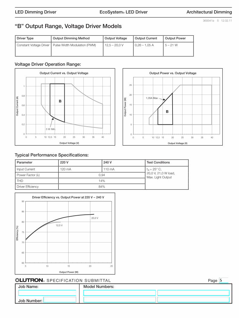
“B” Output Range, Voltage Driver Models
0
0,2
0,4
0,6
0,8
1
0 5 10 12,5 15 20 25 30 35 40
Output Current vs. Output Voltage
Output Voltage (V)
Out
put
Cur
rent
(A)
Output Power vs. Output Voltage
Output Voltage (V)
Out
put
Po
wer
(W)
0
5
10
15
20
25
0 5 10 15 20 25 30 35 40
Output Power (W)
Effi
cien
cy (%
)
Driver Efficiency vs. Output Power at 220 V – 240 V
60
65
70
75
80
85
90
5 10 15 20 25
12,5
B
B
5 W Min.
1,05A Max.
20,0 V
12,5 V
Voltage Driver Operation Range:
Typical Performance Specifications:
0
0,2
0,4
0,6
0,8
1
0 5 10 12,5 15 20 25 30 35 40
Output Current vs. Output Voltage
Output Voltage (V)
Out
put
Cur
rent
(A)
Output Power vs. Output Voltage
Output Voltage (V)
Out
put
Po
wer
(W)
0
5
10
15
20
25
0 5 10 15 20 25 30 35 40
Output Power (W)
Effi
cien
cy (%
)
Driver Efficiency vs. Output Power at 220 V – 240 V
60
65
70
75
80
85
90
5 10 15 20 25
12,5
B
B
5 W Min.
1,05A Max.
20,0 V
12,5 V
Parameter 220 V 240 V Test Conditions
InputCurrent 120mA 110mA ta =25°C, 20,0V,21,0Wload, Max.LightOutput
PowerFactor(λ) 0,94
THD 14%
Driver Efficiency 84%
Driver Type Output Dimming Method Output Voltage Output Current Output Power
ConstantVoltageDriver PulseWidthModulation(PWM) 12,5–20,0V 0,26–1,05A 5–21W

® Specif icat ion Submittal page
Job Name:
Job Number:
Model Numbers:
LED Dimming Driver EcoSystem® LED Driver Architectural Dimming
369341a 6 12.02.11
“C” Output Range, Voltage Driver Models
0
0,2
0,4
0,6
0,8
1
0 5 10 15 20,5 24 30 35 40
Output Current vs. Output Voltage
Output Voltage (V)
Out
put
Cur
rent
(A)
Output Power vs. Output Voltage
Output Voltage (V)
Out
put
Po
wer
(W)
0
5
10
15
20
25
0 5 10 15 24 30 35 40
Output Power (W)
Effi
cien
cy (%
)
Driver Efficiency vs. Output Power at 220 V – 240 V
60
65
70
75
80
85
90
5 10 15 20 25
20,5
1,05A Max.
20,5 V24,0 V
C
C
5 W Min.
Voltage Driver Operation Range:
Typical Performance Specifications:
0
0,2
0,4
0,6
0,8
1
0 5 10 15 20,5 24 30 35 40
Output Current vs. Output Voltage
Output Voltage (V)
Out
put
Cur
rent
(A)
Output Power vs. Output Voltage
Output Voltage (V)
Out
put
Po
wer
(W)
0
5
10
15
20
25
0 5 10 15 24 30 35 40
Output Power (W)
Effi
cien
cy (%
)
Driver Efficiency vs. Output Power at 220 V – 240 V
60
65
70
75
80
85
90
5 10 15 20 25
20,5
1,05A Max.
20,5 V24,0 V
C
C
5 W Min.
Parameter 220 V 240 V Test Conditions
InputCurrent 135mA 130mA ta =25°C, 24,0V,25,0Wload, Max.LightOutput
PowerFactor(λ) 0,96
THD 12%
Driver Efficiency 85%
Driver Type Output Dimming Method Output Voltage Output Current Output Power
ConstantVoltageDriver PulseWidthModulation(PWM) 20,5–24,0V 0,21–1,05A 5–25W

® Specif icat ion Submittal page
Job Name:
Job Number:
Model Numbers:
LED Dimming Driver EcoSystem® LED Driver Architectural Dimming
369341a 7 12.02.11
“D” Output Range, Voltage Driver Models
0
0,2
0,4
0,6
0,8
1
0 5 10 15 20 24,5 30 35 40
Output Current vs. Output Voltage
Output Voltage (V)
Out
put
Cur
rent
(A)
Output Power vs. Output Voltage
Output Voltage (V)
Out
put
Po
wer
(W)
0
5
10
15
20
25
0 5 10 15 24,5 30 35 40
Output Power (W)
Effi
cien
cy (%
)
Driver Efficiency vs. Output Power at 220 V – 240 V
60
65
70
75
80
85
90
5 10 15 20 25
20
40,0 V
24,5 V
5 W Min.
25 W Max.
D
D
Voltage Driver Operation Range:
Typical Performance Specifications:
0
0,2
0,4
0,6
0,8
1
0 5 10 15 20 24,5 30 35 40
Output Current vs. Output Voltage
Output Voltage (V)
Out
put
Cur
rent
(A)
Output Power vs. Output Voltage
Output Voltage (V)
Out
put
Po
wer
(W)
0
5
10
15
20
25
0 5 10 15 24,5 30 35 40
Output Power (W)
Effi
cien
cy (%
)
Driver Efficiency vs. Output Power at 220 V – 240 V
60
65
70
75
80
85
90
5 10 15 20 25
20
40,0 V
24,5 V
5 W Min.
25 W Max.
D
D
Parameter 220 V 240 V Test Conditions
InputCurrent 140mA 130mA ta =25°C, 40,0V,25,0Wload, Max.LightOutput
PowerFactor(λ) 0,96
THD 10%
Driver Efficiency 85%
Driver Type Output Dimming Method Output Voltage Output Current Output Power
ConstantVoltageDriver PulseWidthModulation(PWM) 24,5–40,0V 0,13–1,02A 5–25W

® Specif icat ion Submittal page
Job Name:
Job Number:
Model Numbers:
LED Dimming Driver EcoSystem® LED Driver Architectural Dimming
369341a 8 12.02.11
“G” Output Range, Current Driver Models
Output Voltage vs. Output Current
Output Current (A)
Out
put
Vo
ltag
e (V
)
Output Power vs. Output Current
Output Current (A)
Out
put
Po
wer
(W)
0
5
10
15
20
25
30
35
40
0 0,2 0,35 0,62 0,8 10
5
10
15
20
25
0 0,2 0,35 0,62 0,8 1
Output Power (W)
Effi
cien
cy (%
)
Driver Efficiency vs. Output Power at 220 V – 240 V
60
65
70
75
80
85
90
5 6 7 8 9 10 11 12 13
0,50 A
0,35 A
0,62 A
5 W Min.
G
G20 V Max.
Current Driver Operation Range:
Typical Performance Specifications:
Output Voltage vs. Output Current
Output Current (A)
Out
put
Vo
ltag
e (V
)
Output Power vs. Output Current
Output Current (A)
Out
put
Po
wer
(W)
0
5
10
15
20
25
30
35
40
0 0,2 0,35 0,62 0,8 10
5
10
15
20
25
0 0,2 0,35 0,62 0,8 1
Output Power (W)
Effi
cien
cy (%
)
Driver Efficiency vs. Output Power at 220 V – 240 V
60
65
70
75
80
85
90
5 6 7 8 9 10 11 12 13
0,50 A
0,35 A
0,62 A
5 W Min.
G
G20 V Max.
Parameter 220 V 240 V Test Conditions
InputCurrent 80mA 75mA ta =25°C, 0,62A,12,4Wload, Max.LightOutput
PowerFactor(λ) 0,89
THD 14%
Driver Efficiency 78%
Driver Type Output Dimming Method Output Voltage Output Current Output Power
ConstantCurrentDriver PulseWidthModulation(PWM) OR ConstantCurrentReduction(CCR)
8,0–20,0V 0,35–0,62A 5–12,4W
® Specif icat ion Submittal page
Job Name:
Job Number:
Model Numbers:
LED Dimming Driver EcoSystem® LED Driver Architectural Dimming
369341a 9 12.02.11
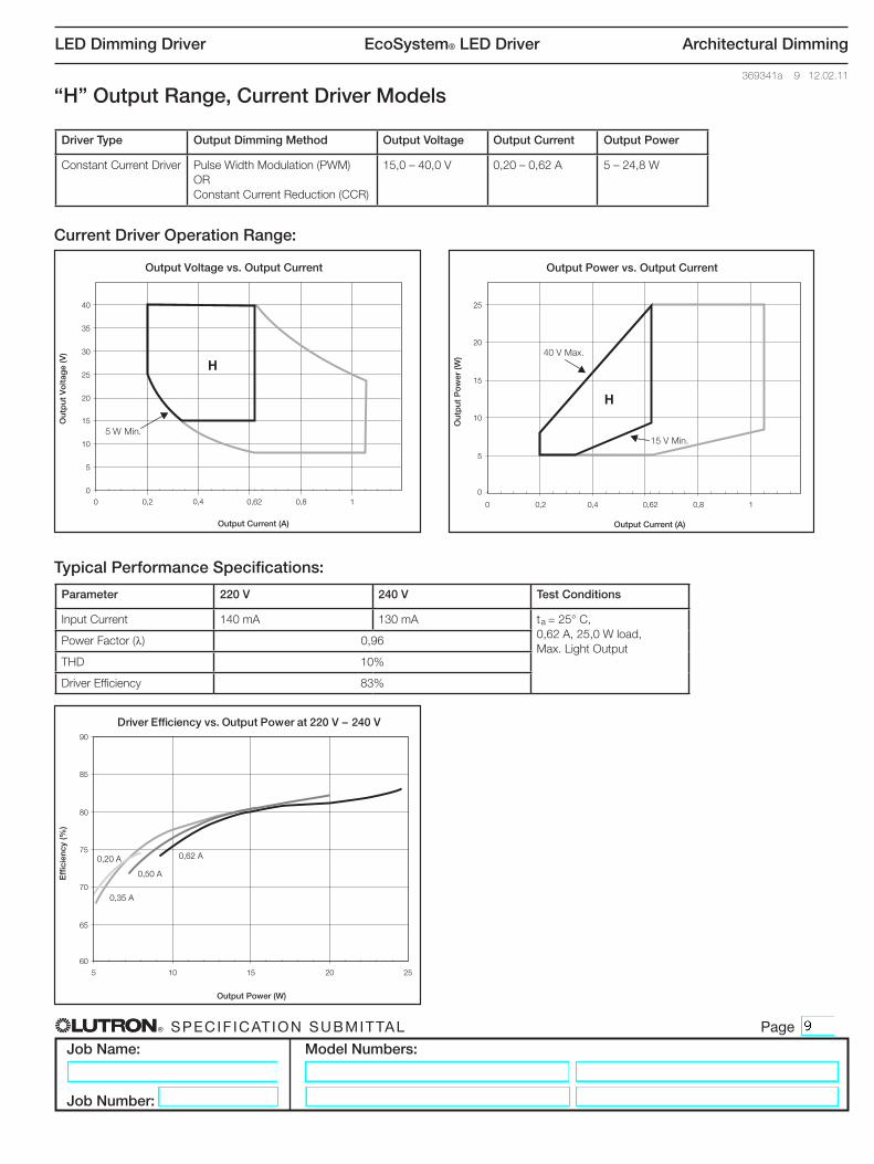
“H” Output Range, Current Driver Models
Output Voltage vs. Output Current
Output Current (A)
Out
put
Vo
ltag
e (V
)
Output Power vs. Output Current
Output Current (A)
Out
put
Po
wer
(W)
0
5
10
15
20
25
30
35
40
0 0,2 0,4 0,62 0,8 10
5
10
15
20
25
0 0,2 0,4 0,62 0,8 1
Output Power (W)
Effi
cien
cy (%
)
Driver Efficiency vs. Output Power at 220 V – 240 V
60
65
70
75
80
85
90
5 10 15 20 25
0,50 A
0,35 A
0,20 A 0,62 A
5 W Min.
H
H40 V Max.
15 V Min.
Current Driver Operation Range:
Typical Performance Specifications:
Output Voltage vs. Output Current
Output Current (A)
Out
put
Vo
ltag
e (V
)
Output Power vs. Output Current
Output Current (A)
Out
put
Po
wer
(W)
0
5
10
15
20
25
30
35
40
0 0,2 0,4 0,62 0,8 10
5
10
15
20
25
0 0,2 0,4 0,62 0,8 1
Output Power (W)
Effi
cien
cy (%
)
Driver Efficiency vs. Output Power at 220 V – 240 V
60
65
70
75
80
85
90
5 10 15 20 25
0,50 A
0,35 A
0,20 A 0,62 A
5 W Min.
H
H40 V Max.
15 V Min.
Parameter 220 V 240 V Test Conditions
InputCurrent 140mA 130mA ta =25°C, 0,62A,25,0Wload, Max.LightOutput
PowerFactor(λ) 0,96
THD 10%
Driver Efficiency 83%
Driver Type Output Dimming Method Output Voltage Output Current Output Power
ConstantCurrentDriver PulseWidthModulation(PWM) OR ConstantCurrentReduction(CCR)
15,0–40,0V 0,20–0,62A 5–24,8W

® Specif icat ion Submittal page
Job Name:
Job Number:
Model Numbers:
LED Dimming Driver EcoSystem® LED Driver Architectural Dimming
369341a 10 12.02.11
“I” Output Range, Current Driver Models
Output Voltage vs. Output Current
Output Current (A)
Out
put
Vo
ltag
e (V
)
Output Power vs. Output Current
Output Current (A)
Out
put
Po
wer
(W)
0
5
10
15
20
25
30
35
40
0 0,2 0,4 0,63 0,8 1,050
5
10
15
20
25
0 0,2 0,4 0,63 0,8 1,05
Output Power (W)
Effi
cien
cy (%
)
Driver Efficiency vs. Output Power at 220 V – 240 V
60
65
70
75
80
85
90
5 10 15 20 25
0,63 A
1,05 A0,70 A
I
I
20 V Max.
8 V Min.
Current Driver Operation Range:
Typical Performance Specifications:
Output Voltage vs. Output Current
Output Current (A)
Out
put
Vo
ltag
e (V
)
Output Power vs. Output Current
Output Current (A)
Out
put
Po
wer
(W)
0
5
10
15
20
25
30
35
40
0 0,2 0,4 0,63 0,8 1,050
5
10
15
20
25
0 0,2 0,4 0,63 0,8 1,05
Output Power (W)
Effi
cien
cy (%
)
Driver Efficiency vs. Output Power at 220 V – 240 V
60
65
70
75
80
85
90
5 10 15 20 25
0,63 A
1,05 A0,70 A
I
I
20 V Max.
8 V Min.
Parameter 220 V 240 V Test Conditions
InputCurrent 125mA 115mA ta =25°C, 1,05A,21,0Wload, Max.LightOutput
PowerFactor(λ) 0,95
THD 14%
Driver Efficiency 81%
Driver Type Output Dimming Method Output Voltage Output Current Output Power
ConstantCurrentDriver PulseWidthModulation(PWM) OR ConstantCurrentReduction(CCR)
8,0–20,0V 0,63–1,05A 5–21W

® Specif icat ion Submittal page
Job Name:
Job Number:
Model Numbers:
LED Dimming Driver EcoSystem® LED Driver Architectural Dimming
369341a 11 12.02.11
“J” Output Range, Current Driver Models
Output Voltage vs. Output Current
Output Current (A)
Out
put
Vo
ltag
e (V
)
Output Power vs. Output Current
Output Current (A)
Out
put
Po
wer
(W)
0
5
10
15
20
25
30
35
40
0 0,2 0,4 0,63 0,8 1,050
5
10
15
20
25
0 0,2 0,4 0,63 0,8 1,05
Output Power (W)
Effi
cien
cy (%
)
Driver Efficiency vs. Output Power at 220 V – 240 V
60
65
70
75
80
85
90
5 10 15 20 25
0,63 A
1,05 A
0,70 A
J
J
15 V Min.
25 W Max.
Current Driver Operation Range:
Typical Performance Specifications:
Output Voltage vs. Output Current
Output Current (A)
Out
put
Vo
ltag
e (V
)
Output Power vs. Output Current
Output Current (A)
Out
put
Po
wer
(W)
0
5
10
15
20
25
30
35
40
0 0,2 0,4 0,63 0,8 1,050
5
10
15
20
25
0 0,2 0,4 0,63 0,8 1,05
Output Power (W)
Effi
cien
cy (%
)
Driver Efficiency vs. Output Power at 220 V – 240 V
60
65
70
75
80
85
90
5 10 15 20 25
0,63 A
1,05 A
0,70 A
J
J
15 V Min.
25 W Max.
Parameter 220 V 240 V Test Conditions
InputCurrent 145mA 135mA ta =25°C, 1,05A,25,0Wload, Max.LightOutput
PowerFactor(λ) 0,96
THD 12%
Driver Efficiency 82%
Driver Type Output Dimming Method Output Voltage Output Current Output Power
ConstantCurrentDriver PulseWidthModulation(PWM) OR ConstantCurrentReduction(CCR)
15,0–39,7V 0,63–1,05A 9,5–25W

® Specif icat ion Submittal page
Job Name:
Job Number:
Model Numbers:
LED Dimming Driver EcoSystem® LED Driver Architectural Dimming
369341a 12 12.02.11
Case Dimensions
A 31,8mmB 89,7mmC 154,7mmD 90mmE 143,5mmF 4,6mmG 34,3mmH 48,6mm
A
CB
Mounting Centers
E
G
H
F
D

® Specif icat ion Submittal page
Job Name:
Job Number:
Model Numbers:
LED Dimming Driver EcoSystem® LED Driver Architectural Dimming
369341a 13 12.02.11
EcoSystem® LED Driver Wiring Diagrams
EcoSystem® Digital Link Overview
•TheEcoSystem®DigitalLinkwiring(E1andE2)connects the drivers together to form a lighting control system
•EachEcoSystem®DigitalLinksupportsupto64EcoSystem®devices,64occupantsensors,16daylightsensors,and64wallstationsorIRreceivers
•E1andE2(EcoSystem®digitallinkwires)arepolarityinsensitiveandcanbewiredinanytopology
•AnEcoSystem® Energi Savr NodeTM module or Quantum® system provides power for the EcoSystem® DigitalLinkandsupportssystemprogramming
•AllEcoSystem®DigitalLinkprogrammingiscompletedbyusingtheEnergiSavrAppforApple iPad, iPod Touch or iPhonemobiledigitaldevices,EcoSystem®Programmer,orQuantum® system
EcoSystem® Digital Link Wiring
•DriverEcoSystem®DigitalLinkterminalsonlyacceptone0,50mm2to1,5mm2 solid copper wire per terminal
•MakesurethatthemainsbreakertotheDriverandEcoSystem®DigitalLinkSupplyisOFFwhenwiring
•ConnectthetwoconductorstothetwoDriverterminalsE1andE2asshown
•UsingtwodifferentcolorsforE1andE2willreduceconfusion when wiring several drivers together
•Consultapplicableelectricalcodesforproperwiringpractices.
Notes
•TheEcoSystem®DigitalLinkSupplydoesnothavetobelocatedattheendoftheDigitalLink
•EcoSystem®DigitalLinklengthislimitedbythewiregaugeusedforE1andE2asfollows:
Wire Size Digital Link Length (max)
4,0mm2 828m2,5mm2 517m1,5mm2 310m1,0mm2 207m0,75mm2 155m0,50mm2 103m
DIGITAL BUSUNIT 1 UNIT 2
E1 E2DIGITAL BUSE1 E2
EcoSystem® Daisy-Chain Wiring
To EcoSystem® Digital Link compatible devices (up to 64 total devices)
Apple,iPad,iPodTouch,andiPhonearetrademarksofAppleInc.,registeredintheU.S.andothercountries.

® Specif icat ion Submittal page
Job Name:
Job Number:
Model Numbers:
LED Dimming Driver EcoSystem® LED Driver Architectural Dimming
369341a 14 12.02.11
Hi-lume A-Series
**
Dimmed Hot
Switched Hot
NeutralGround
To3-wire
DimmingControl
+V
Ground*
-V†
†
LED light engine
Dimmed Hot
Live
Neutral
ToMains
ToEcoSystem®
digital link
-V
E1
E2
+V
*
*
LED light engine
Hi-lume A-Series
**
Dimmed Hot
NeutralGround
To ELVDimmingControl
+V
Ground*
-V†
†
LED light engine
RED
BLUE
YELLOW
BLUE/WHITE
LAMPS
7 ft Max. lead length
P/N
500-
1336
2 R
ev. A
NEU
N/C
SH
B/W
B/W
BLU
BLU
RED
YEL
YEL
E1
E2
NEUTRAL
SWITCHED HOT
TO
EcoS
yste
m® H
BUS
E1
E2
Ecosystem® H Ballast
CALIB
RATION
P O I N TCoopersburg, PA 18036 USA RED
Programmed Rapid Start 1% Electronic Fluorescent Dimming Ballast
CLASS 2 BUS
LINE
®
Solid 18 or 16 AWG wire for power and bus terminals 18 AWG wire only for lamps.
5/16 in (8 mm)
1-800-523-9466
Copper wire only
Consult lamp manufacturer for lamp seasoning requirements prior to dimming.
Warranty void if unit is opened.
WARNING: Shock hazard. May result in serious injury or death. Disconnect power before servicing or installing.
Calibration point temperature not to exceed 65 °C.Maximum case temperature 75 °C.
Ecosystem® H
TO LI
NEVO
LTAG
ESO
URCE
Pantone362
500-13362 Rev. ALabel Size: 6.87” x 2.125” Corner Radius: 0.0625”
Colors:Pantone186
Pantone1585
Pantone116
Pantone3005
Pantone2583
PantoneBlack
EcoSystem® LED Driver
Wiring Diagram for EcoSystem® Digital Control
*Maximumlamp-to-driverwirelengthis2mforanyoutputtype.
ATTENTION ELECTRICIANS AND CONTRACTORS
Driver Leads
Lead lengths from driver to LED light engine must notexceed3m.
Wiring
Driversmustbeinstalledpernationalandlocalelectrical codes.
ATTENTION FACILITIES MANAGERS
SERVICE
Warranty
Forwarrantyinformation,pleasevisit http://www.lutron.com/TechnicalDocumentLibrary/Ballast%20and%20Driver%20Warranty.pdf
Replacement Parts
UsereplacementpartswithexactLutronmodel numbers.ConsultLutronifyouhaveanyquestions.
Contact Information
Forfurtherinformation,pleasevisitusat europe.lutron.com or contact Lutron Technical Support at +44.(0)20.7680.4481(Europe)or 1.800.523.9466(USA,Canada,Caribbean).