ecom · 2014-10-23 · ecom-4451 historyofthe squad radio o o marvin w. curtis communications/adp...
TRANSCRIPT
,J****i'-
CO
00 CO o <
Research and Development Technical Report
ECOM-4451
HISTORYOFTHE SQUAD RADIO
O O
Marvin W. Curtis
Communications/ADP Laboratory
November 1976
DISTRIBUTION STATEMENT
Approved for public release, distribution unlimited.
ECOM
- D D C msiEiEQEfn)
j4 APR 19 1977
0
US ARMY ELECTRONICS COMMAND FORT MONMOUTH, NEW JERSEY 07703
.
.

NOTICES
Discloiffltrs
The findings in this report are not to be construed as an official Department of the Army position, unless so desig- nated by other authorised documents.
The citation of trade names and names of manufacturers in this report is not to be construed as official Government indorsement or approval of commercial products or services referenced herein.
Disposition
Destroy this report when it is no longer needed. Do not return it to the originator.
„.•,>vi(S»K:«
UNCLASSIFIED SECURITY CLASSIFICATION OF THIS PAGE fWiwi Dim Bnttttd)
(B r REPORT DOCUMENTATION PAGE
«eposti ECOM - ^51
2. OOVT ACCESSION NO
READ INSTRUCTIONS BEFORE COMPLETING FORM
S. RECIPIENT'S CATALOG NUMIER
■T
4. TITLE r«n<<Su»M(/.J
HISTORY OF THE SQUAD RADIO <■
S. TYPE OF REPORT * PERIOD COVERED
Final ffev&rt i^Jj' Final/epoiH ^ |
7. AUTHOR^
MARVIN W./CURTIS
9. PERFORMING ORGANISATION NAME AND ADDRESS Communications/ADP Laboratory > DRSEL-NL-D-1* Fort Monmouth, New Jersey 0T703
11. CONTROLLING OFFICE NAME AND ADDRESS
Communications/ADP Laboratory DRSEL-NL-D-1« Fort Monmouth, New Jersey 07703
/L
*■ MONITORING AGENCY NAME » AODRESSC«/ dIHnml /ran Centroll/nf Otlle»)
RT NUMIER
S. CONTRACT OR ORANT NUMIERfa)
10. PROGRAM ELEMENT. PROJECT, TASK AREA • WORK UNIT NUMIERS
P3flflZ5aQ3QQ0QQ30flQQflQ 12. REPORT OAT5___
Novwiwr l??^ NUMBKR OF""PÄOiK ""
87 IS. SECURITY CLASS, (at Mi ttport)
Unclassified
IS«. OECLASSIFICATION/DOWNORADINO SCHEDULE
IS. DISTRIBUTION STATEMENT (et Mt Rtpo'D
Approved for public release; distribution unlimited ICH IV
17. DISTRIBUTION STATEMENT (ol Iht tbtlrtcl tnffd In Block 30, II dllltrtnl horn Report)
wmie SictiN
lütt SKtiN n
!EO n
V
II. SUPPLEMENTARY NOTES
v;j(10H/«»ILADILIir CODES
.—ZmiÜMiiJiiM
f\ IS. KEY WORDS (Contltiu» on raroro* «Mo II n»et»»mT mtd lOtnllty tf blcek number;
Radio Set AN/PRC-6; Handi-Talkie; Radio Set AN/PRC-15; Cigarette Case Radio; Radio Set AN/PRC-SO; Radio Set AN/PRC-35; Helmet Radio; Squad Radio.
\
20kjkBSTRACT (Cantlnut on ranrM old* If oMMMfp ma IdnUlly if Ueek umSOi "
This report details the history of the squad radio from its Inception as an idea to its culmination as an end item.
DO 1 JAN 71 1473 COITION OF I NOV SI II OBSOLETE UNCLASSIFIED
SECURITY CLASSIFICATION OF THIS PAOE fWion DM« tntmt)
t.H .-•■
■ •

SECURITY CLASSIFICATION OF THIS PAOEWian Dmlm Knitnd)
SECURITY CLASSIFICATION OF THIS PAOEflTh.n Data Bnltttd)

TABLE OF CONTEMS
Page
1. REQUIREMENTS FOR RADIO SET AN/PRC-6 STAIED 1
2. DEVELOPMEm: OF TOE "HANDI-TAIiOE" 1
3. REQUIREMENTS FOR A PIAT00N-TO-SQUAD RADIO: THE AN/PRC-15 2
4. DEVEIXBfOT OF THE AN/PRC-15 2
5. DEVEIJOPMEOT CF TOE SUB-MINTATURE CIGARETTE CASE RADIO 6
6. SERVICE TEST MDDELS OF THE AN/PRC-15 ARE PROCURED 6
7. OTHER FORMS CONSIDERED FOR THE AN/PRC-15 8
8. DEVELOPMENT OF TRANSISTORS AND RADIO SET AN/PRC-30^ 11
9. CHANGES IN REQUIREMENTS FOR ARMJf FIELD CCMUNICATIONS 11
10. FOREIGN RADIO EQUIPMENT 14
11. REQUIREMENTS ESTABLISHED FOR RADIO SET AN/PRC-35 14
12. DEVELOPMENT OF RADIO RECEIVER FOR INDIVIDUAL RIFIZMAN 21
13. SEARCH FOR A HELMET RADIO 24
14. CONCEPT TEST OF HEIMEr RADIOS 25
15. FIELD TESTS OF HELMET RADIOS ^ •... 27
16. USING MICRCmXJIES FOR RADIO EQUIPMENT 31
17. FINAL DESIGN OF THE SQUAD RADIO 31
18. OBJECnONS TO CCMERCIAL BQUIIMENT 32
19. MAJOR CHANGE IN QUALITATIVE MATERIEL REQUIREMENTS (CMR) 34
20. SCEL RECEIVES FINAL APPROVED QMR 36
21. PROBLEMS WITH FINAL DESIGNS 36
22. CONTRACT PIACED WITH DELOO RADIO 47
23. OTHER ITEMS REQUIRED ON DELOO RADIO CONIRACI 47
.t ..
,
Page
24. SEmCE TEST OF TOE SQUAD RADIO 53
25. THE DEVEIX)PhlEOT ACCEPTANCE IN PROCESS REVIEW 53
26. PRODUCTION 56
27. FIELDING 56
28. CURRENT STATUS 58
29. THE FinURE 58
LIST OF FIGURES
Figure I Production model of Radio Set AN/PRC-6 ("Handi-Talkie") 3
Figure 2 Technical characteristics of Radio Set AN/PRC-6 4
Figure 3 Technical characteristics of Radio Set AN/PRC-15 5
Figure 4 Sub-miniature cigarette case radio 7
Figure 5 Radio Set AN/PRC-15 (Service-Test Madel) 9
Figure 6 Technical characteristics of Radio Set AN/PRC-15 10
Figure 7 Radio Set AN/PRC-30 12
Figure 8 Technical characteristics of Radio Set AN/PRC-30 13
Figure 9 Canadian Squad Radio CPRC-26 15
Figure 10 Technical characteristics of Canadian Squad Radio CPRC-26... 16
Figure 11 Danish Radio Set DA/PRC-260 17
Figure 12 Technical characteristics of Danish Radio Set DA/PRC-260.... 18
Figure 13 French Radio Set TR-PP-11A 19
Figure 14 Technical characteristics of French Radio Set TR-PP-11A 20
Figure 15 Radio Set AN/PRC-35 22
Figure 16 Technical characteristics of Radio Set AN/PRC-35 23
Figure 17 Radio Set AN/PRC-34 mounted in helmet (experimental) 26
Figure 18 Radio Set AN/PRC-34 (Development Model). Overall view, showing operator using microphone 28
11

Page
Figure 19 Radio Set AN/PRC-36 (Development Model). Overall view, showing antenna mounted on helmet liner and operator using tone button 29
Figure 20 Technical characteristics of Radio Sets AN/PRC-34 and AN/PRC-36 30
Figure 21 Proposed (J1R for a lightweight radio transmitter and receiver (January 1961) 33
Figure 22 Major changes in previously proposed (JMR 33
Figure 23 Approved final QMR for intra-squad radio 37
Figure 24 Various mock-ups of case designs proposed for Radio Receiver AN/PRR-9 38
Figure 25 Mack-up of Radio Transnifter AN/PRT-4 showing proposed lanyard and folding antenna 39
Figure 26 Mock-up of Radio Transmitter AN/PRT-4 showing flexibility of telescopic antenna with spring-loaded bead base 40
Figure 27 Mock-up of Radio Transmitter AN/PRT-4 showing telescopic antenna with ball swivel base (collapsed) 41
Figure 28 Mock-vp of Radio Transmitter AN/PRT-4 showing battery held in position with a proposed elastic strap 43
Figure 29 Mock-up of Radio Transmitter AN/PRT-4 showing adjustable battery strap. ^
Figure 30 Radio Receiver AN/PRR-9 (XE-1) and Radio Transmitter AN/PRT-4 (XE-1) 45
Figure 31 Radio Transmitter AN/PRT-4 (XE-2) and Radio Receiver AN/PRR-9 (XE-3) 46
Figure 32 Preproduction model of Radio Transmitter AN/PRT-4 48
Figure 33 Preproduction model of Radio Receiver AN/PRR-9 49
Figure 34 Final Technical characteristics of Radio Transmitter AN/PRT-4 and Radio Receiver AN/PRR-9 50
Figure 35 Alignment jig for final models of Radio Transmitter AN/PRT-4 and Radio Receiver AN/PRR-9 51
Figure 36 Crystal Kit for final models of Radio Transmitter AN/PRT-4 and Radio Receiver AN/PRR-9 52
iii
. .. i ■.-*■■..

Figure 37 Radio Test Set for final models of Radio Transmitter AN/PRT-4 and Radio Receiver AN/PRR-9 54
Figure 38 Battery tester for final models of Radio Transmitter AN/PRT-4 and Radio Receiver AN/PRR-9 55
APPENDIXES
I. Letter Sent by 2nd Ranger Battalion on Field Testing of Squad Radios.
Page 1 60
Page 2 61
II. Supplementary Figures
Figure SI. Individual Radio Concept 62
Figure S2. Curved >fadel of Radio Set AN/PRC-6 63
Figure S3. Receiver - Transmitter RT-( )/PRC-6 (XC-2) and Antenna AT-( )/PRC-6 (XC-2) part of Radio Set AN/PRC-6 (XC-2) Antenna shown connected to receiver-transmitter 64
Figure S4. Radio Set AN/PRC-34 (developmant model). Receiver - Transmitter (less microphone) shown mounted in interior of helmet 65
Figure S5. Radio Set AN/PRC-34 (Service-test model). Helmet (less microphone) shown with antenna up 66
Figure S6. Radio Set AN/PRC-36 (development model). Antenna shown nounted on radio set and acoustic accessories mounted on standard helmet liner 67
Figure S7. Developmental model of Radio Transmitter AN/PRT-4 68
Figure S8. Final model of Radio Receiver AN/PRR-9 69
Figure S9. Radio Receiver AN/PRR-9 and Radio Transmitter AN/PRT-4 (showing set in operation, with receiver mounted on helmet) 70
Figure 810. Radio Transmitter AN/PRT-4 and Radio Receiver AN/PRR-9 (showing transmitter on harness, with transmitter antenna extended and receiver mounted on helmet) 71
iv
.. -;.*ti-_.. .

Page Figure SU. Radio Transnitter AN/PRT-4 and Radio Receiver
AN/PRR-9 (stowing receiver and transmitcer In operator's pockets, with ear plug In use) • 72
Figure S12. Radio TransmLtter AN/PRT-4 and Radio Receiver AN/PRR-9 (showing transmitter hooked on harness, with antenna collapsed and receiver mounted on helmet) -73
III. Supplementary Memoranda
NOTE 74
SM-1. Draft Report of Project No. CE4752, MLlitary Characteristics for Radio Receiver for Individual Rifleman 75
SM-2. Meno for Record: B/L G3 413.44 (18 Nov 53), AC of S, G-3, Operations to OCAFF, dtd 18 Nov 53, Subject: Miniature Radio Receiver 76
SM-3. 1st Indorsement, Subject: Miniature Radio Receiver, Office, Chief of Amy Field Forces, Fort Manroe, Virginia,23 Dec 53. .77
SM-4. AIDH 420, Subject: Taiik Helmet Radio, 14 Dec 54 78
SM-5. 1st Indorsement, SIGEL-CRB-4, Project SC1R (14 Dec 54), Subject: Tank Helmet Radio 79
SM-6. Memorandum Report, Coles Signal Laboratory, SCEL, 8 June 55, Subject: Conmunications Equipment for Forward Area Confcat Personnel 80
SM-7. Work Directive CE-29R, Subject: Purpose of Project and Ccmnents 81
SM-8. Memorandum for Lieutenant General James M. Gavin, Subject: Division Test of Individual Soldier's Radio, 10 Sept 55 82
SM-9. 2nd Indorsement, DA OC SigO, Subject: Portable Radio Sets for Riflemen, 25 Jan 56 83
SM-10. Memorandun Report, Comnunications Department, USASRDL, Subject: Report of Trip to Hq, US00NARC, Fort Mxiroe, Virginia on 26 Apr 60, re: Helmet Set Radio, dated 28 April 1960 84
SM-U. Letter, Office of the Chief Signal Officer, Subject: Squad Radio Set, dated July 27, 61 85
SM-12. Chief of Staff Report, Subject: Miniature Radios, Lt. Col. Pierce, No Date 86
SM-13. Letter, Office of the Chief Signal Officer, Subject: Squad Radio Set, No Date 87
V

HISTORY OF THE SQUAD RADIO
1. REQUIREMEWrS FOR RADIO SET AN/PRC-6 STATED
Requirements for Radio Set AN/PRC-6 were formally stated in March 1945
Intended primarily as a replacement for Radio Set SCR-536, the PRC-6 was
to be used as a means of conraunication between foot troops of the nest
forward elements (company-platoon) and between infantry and close-support
armored elements. This new set had to be conpatible with Radio Sets SCR-
300 and GRC-3 throu^i 8 (B) and had to have a range of 300 yards in jungle
and 1 mile in rolling terrain. As to weight, it could weig^i a maxiinum of
nine pomds, but six pounds was considered desirable. Its size and shape
had to be such that it could easily be concealed. The radio set and its
battery could be separate to facilitate concealment on the body. Its mode
of operation was to be FM-voice modulation, with 1 preset and 44 possible
channels. The battery had to have a miniitun life of 4 hours, with a 2:1
receive-transnit ratio. And, lastly, shape of microphone and headset had
to be such as to permit free use of the hands.
2. DEVELOPMSNT OF THE "HANDI-IALKIE"
At the outset, as a result of opinions from Army personnel as to the
most desirable form the AN/PRC-6 should take, several configurations were
made. The initial development model was made by fötorola and was curved to
fit the body to facilitate concealment (Figure S1A). In conparison with
other FM equipment, this receiver-transmitter using miniature tubes was very
ligftt, but required an 11-pound battery for operation.
While the contractual development of the PRC-6 was taking place, the
laboratories were carrying en a parallel development of this equipment,
utilizing newly developed subtidniature tubes. These new tubes enabled the
Aifiitoi.
laboratories to design and enploy a new W circuit vhich eliminated the
requirement for a chain of multiplier stages. The resultant circuit
substantially reduced the radio's power input requirements, pemtLtting a
realistic desigi for the AN/PRC-6. To continue development of the set
along these lines, a contract was let to Raytheon with the ultimate aim
of producing a squad radio vMch could be manufactured. Raytheon succeeded
in its final laboratory model in reuniting the receiver-transmitter and
battery in one case, resulting in the production of the final model of the
AN/PRC-6, known as the "Handi-Talkie" (Figure 1), whose technical
characteristics are shown in Figure 2.
3. REQUIREMEKTS FOR A PIATOON-TO-SQUAD RADIO: the AN/PRC-15
After Che development of the AN/PRC-6, designed as a means of
conmunication between foot troops in the most forward elements and between
infantry and close-support armored elements, came the requirement for a
radio set capable of providing coimunications from platoon to squad.
Designated the AN/PRC-15, it was designed as a portable short-range
transceiver specifically for conmunication between infantry squad leaders
and platoon leaders. Its technical characteristics were to be those given
in Figure 3.
4. DEVELOPMENT OF THE AN/PRC-15
To achieve these, the laboratories in their design of the AN/PRC-15
enbarked on an intensive development of applicable circuitry and assenbly
techniques. In so doing, the designers were confronted with two
alternatives. Should they begin with a radio set such as the AN/PRC-6
which had the required performance characteristics and progressively reduce
its dimensions as new conponents and techniques became available, or begin

Ct.- ,
Figure 1. Production npdel of Radio Set AN/PRC-6 ("Handi-Talkle"),

A. General:
1. Frequency Range: 47 - 55.4 Mc
2. Available Channels: 43 0 200 kc spacing
3. Nunber of Preset Frequencies: 1
4. Range: 1 mile
5. DlnEnsions: 14" x 5 1/2" x 4 1/4"
6. Weight: 6.75 pounds
B. Receiver:
1. Sensitivity: 0.7 ndcrovolts
2. Power Drain: 490 Ma @ 1.25 volts (.613 watts) ) ) 1.2&8 watts
15 Ma @ 45 volts (.675 watts) )
C. Transmitter:
1. Power Output: 250 milliwatts
2. Type of Modulation: Voice, FM, 15 kc deviation
3. Power Drain: 1.05 anperes 0 1.25 volts (1.30 watts)
45 Ma (§ 45 volts (2.03 watts)
30 Ma 9 90 volts (2.70 watts)
Total: 6.0 watts
Figure 2. Technical characteristics of Radio Set AN/PRC-6 .
-

Date: July 1947
Purpose: To provide a portable, short-range transceiver designed
specifically for camunication between Infantry Squad Leaders and
Platoon Leaders.
1. Frequency: Capable of netting with AN/PRC-6
2. Ninber of Channels: 6 nummum
3. Nuiter of Presets: 2
4. Range: 500 yards
5. Size: 8 cubic inches maxinun desirable
6. Weight: 1 pound maxinun desired
7. Form Factor: 1 package arm mounted
8. Battery Life: 10 hours.
NOTE: The Laboratories stated that the desired size and weight were
considerably beyond the state of the art. On 3 Decenber 1947, Hq AGF
BD No.l, Fort Bragg approved a 2.5 pound weight and a 40 cu in volune
for experimental models.
Figure 3. Technical characteristics of Radio Set AN/PRC-15.
5
. .

with a set that had the required dimensions but not the required performance
and progressively inprove the performance?
5. DEVELORIEKr OF THE SUB-MINIATURE CIGARETIE CASE RADIO
In investigating these alternatives, the most outstanding result, and
one vMch achieved nationwide attention, was the development of a 12-ounce
radio, whose size was no bigger than a "king-size" package of cigarettes
(Figure 4). When one considers the stage of development of electronics at
the time, the size and weight that were achieved with this transceiver are
indeed incredible. However, its military potential was not too bright.
Operational tests of the set in the 50 mc region indicated that its reliable
range was 200 yards over average rolling terrain. These tests also indicated
that the state of electronics, as exemplified by this set, had not advanced
to the point where this equipment could be offered as a military radio set.
In addition, during tests such problems as frequency stability and receiver
radiation were encountered which indicated that' the radio would not be able
to fulfill its systems requirements. Add to this that the technique used
for the equipment's construction made it impossible for the AN/FRC-15 to
meet its inplied requirements because it could not be produced rapidly and
economically. What the development of this radio only served to bring out
was that its desigji had limitations and that the nunber of problems involved
in getting the set to meet its governing military requirements vrould be
many. Yet, the great quantities in vhich this set would have to be turned
out made it inperative that its desigp be such that it could be manufactured
easily and economically.
6. SERVICE TEST M3DELS OF THE AN/FRC-15 ARE PROCURED
The outcome of this investigation and testing was a technical develop-
ment specification and a decision to procure service test models of the
6
^fc-jriSi.... :

Figure 4. Sub-miniature cigarette case radio.
.

PRC-15. For this, a contract was let to Mitchel Industries, Mineral Wells,
Texas for the development and fabrication of these models. It was
acknowledged at the outset that this contract would not result in equipment
that would be of the required size and weight specified by the military
characteristics. Hcwever, it was felt that interim models and advancement
in the design of subndniature radio sets would result.
7. OIHER FORMS CONSIDERED FOR THE AN/PRC-15
Inasmuch, then, that the desired weight and size could not be achieved,
other forms for the PRC-15 were considered other than those which could be
strapped on the arm. The first of these was a bib model, ^lich could be
carried on the chest directly under the chin, and whose mLcrophone was
attached to an arm which, v*ien pushed by the chin, actuated a transmitter.
The AFF Board No. 1 before viiom this model yas demonstrated in January
1951 expressed dissatisfaction with its size, weight, and shape. Instead,
it suggested that the radio be shaped like a pistol holder, in vMch form it «
could be carried under the arm. For this the laboratories projected an
ultimate size of 50 cubic inches and weight of 3 to 3% pounds. The question
of a firm requirement for the equipment described by the MC's arose, and the
Board indicated the characteristics would be reviewed. Even with its
obvious deficiencies, the test model had some advantages over the AN/PRC-6
in that it could be used with artillery and infantry heavy weapons vnits.
It was agreed that the remainder of the test units should be fabricated with
some modifications and delivered to the board for test (Figure 5). Final
models of the AN/PRC-15 were delivered early in 1954 and had the technical
characteristics listed in Figure 6. Service test of this final model
shewed that it met one of the military characteristics in that it did have
a transmission range in excess of 500 yards. However, it failed to meet the 8
.

Figure 5. Radio Set AN/PRC-15 (Service-test model).

A. General:
1. Frfciiaacy Range: A7.0 - 55.4 Mc
2. Available Channels: 43 @ 200 kc spacing
3. Nuiber of Preset Frequencies: 2
4. Range: 500 - 1000 yards
5. Diirensions: 2 3/8" x 2 1/2" x 10 1/2"
6. Weight: 3 pounds 6 ounces
B. Receiver:
1. Sensitivity: 1.5 microvolts
2. Power Drain: 12 Ma @ 45 volts (0.54 watts) ) ) 1.17 watts
500 Ma (3 1.25 volts (0.63 watts) )
C. Transmitter:
1. Power Output: 100 milliwatts
2. Type of Madidation: Voice, FM
3. Power Drain: 24 Ma @ 45 volts (1.08 watts) ) ) 1.78 watts
560 Ma 0 1.25 volts (0.70 watts) )
Figure 6. Technical characteristics of Radio Set AN/PRC-15.
10
.

requirements of size, weight, form, battery life, and volune control. The
draft of the service reports In which these failures were emmerated also
went on to state that the set could not be worn and concealed on the arm,
but had to be held In the hand and was actually a miniature version of
Radio Set AN/PRC-6, but without the facilities for external audio
accessories. The report concluded that the set would have to be completely
redesigied to meet the required military characteristics. Neither the
Infantry School nor the Armor School recomnended the adoption of Radio Set
AN/FRC-15 as a standard type.
8. DEVELOPMENT OF TRANSIgTORS AND RADIO SET AN/PRC-30
These conclusions came as no surprise for the Laboratories had stated
that the requirements for the AN/PRC-15 could not be achieved, considering
the current state of electronics. However, the development of transistors
of military quality and performance in 1953 gave new impetus to satisfying
the requirements for a small, li^itwei^it transceiver. In 1954, a contract
was let to Galvin Industries (Motorola) for the development of Radio Set
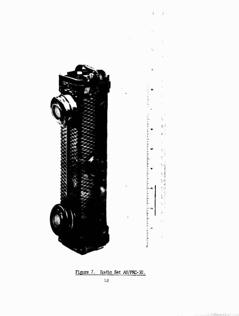
AN/PRC-30 (Figure 7). In 1958, the final model was delivered, whose
technical characteristics were those listed in Figure 8. But the FRC-30
was not submitted for service test because CONARC, as a result of re-
evaluating the tactical portable equipment program, withdrew the military
characteristics for this equipment.
9. CHANGES IN REQUIREMENrS FOR ATOg FIELD OOMINICATIONS
In fact, between 1953 and 1958 two important changes took place in the
requirements for arm/ field comunications. The first was that the require-
ment of 500 yards for the AN/FRC-15 and AN/FRC-30 was Increased to one mile.
And the second was the first statement of a recognized potential need for
radio camtnicatlons from squad leader to all or key merfcers of his squad.
11
-1
Figure 7. Radio Set AN/PRC-30.
12
. .^fiifiAu.- .

A. General:
1. Frequency Range: 25 - 50 Mc
2. Available Channels: 500 (? 50 kc spacing
3. Nunber of Preset Frequencies: 2
4. Pange: 500 - 1000 yards
5. Dinfinsions: 2" x 2M x 8 V'
6. Weight: 2 pounds 12 ounces with antenna and battery
B. Receiver:
1. Sensitivity: 2 microvolts
2. Power Drain: 15 Ma Q 4.5 volts (.068 watts) ) ) .076 watts
5 Ma (a 1.5 volts (.008 watts) )
C. Transmitter:
1. Power Output: 100 milliwatts
2. Type of Modulation: Voice, EM, 7 to 20 kc deviation
3. Power Drain: 250 Ma (3 4.5 volts (1.13 watts)) ) 1.81 watts
450 Ma (3 1.5 volts ( .68 watts))
Figure 8. Technical characteristics of Radio Set AN/PRC-30.
13
..- '■' ■..-f_t* .:. ^ _■ '

10. FOREIGN RADIO EQUIFMENr.
One must always keep lit mind that during this same period, 1952-1958,
the Canadians, Danes, and French, nctivated not only by national pride but also dissatisfied with the AN/PRC-S's shape and nuiber of available
channels, began to develop their own equipment. At the same time, considerable disagreement existed within the US Army concerning the optimum nunber of channels that a squad leader should have. The need for maximum flexibility to permit movement from unusable äharmels indicated
a need for 2, A, or 6 channels. But the possibility of chaos resulting from an operator operating on unautliarized frequencies or a squad leader nünitoring one channel vMle being called on another gave strong support to the argument for the Amy's roiHining with the single-channel AN/PRC-6. And, so, against this background and during this period, the Canadians produced a squad radio with the nomenclature of CPRC-26 (Figure 9). Its characteristics are listed in Figure 10. It was tested and evaluated in the field but was rejected as offering no significant advantage over the PRC-6. The Danes produced the DA/PRC-260 (Figure 11), a transistorized version of the Canadian equipment, putting it in the same box and using a smaller battery. Its technical characteristics are shown in Figure 12.
But they only succeeded in reducing the weight of the equipment cne
pound. The French produced a smaller version of the AN/PRC-6 with six channels and gave it the nomenclature of TR-PP-11A (Figure 13). It
received a US field evaluation but was not recommended for adoption. Its
technical characteristics are described in Figure 14.
11. REQUIREMEMS ESTABLISHED FOR RADIO SET AN/PRC-35
In the requirements for the family of Radio Sets AN/VRC-12 and
AN/PRC-25 was included one that they replace the AN/PRC-6. This equipment was given the nomenclature of Radio Set AN/PRC-26 but was later changed to AN/PRC-35 to avoid confusion with the Canadian CPRC-26. The Laboratories atterpt to incorporate all the required features of a
squad radio into the PRC-35 (Figure 15).
14

Figure 9. Canadian Squad Radio CPRC-26.
15

A. General:
L. Frequency Range: 47-55.4 Mc
2. Available Channels: 43 (5 200 kc spacing
3. Munter of preset frequencies: 6
4. Range: 1 mile
5. Diransions: 10 5/8" x 5" x 3 1/8"
6. Weight: 6.5 pounds
B. Receiver:
1. Sensitivity: 2 microvolts
2. Power Drain: 550 Ma @ 1.5 volts (.825 watts)
14 Ma (3 45 volts (.63 watts)
3 Ma @ 90 volts (.27 watts)
C. Transmitter:
1. Power Output: 150 - 350 Milliwatts
2. Type of Modulation: Voice, M, 15 kc deviation
3. Power Drain: 900 Ma (3 1.5 volts (1.35 watts)
8 Ma (? 45 volts (0.36 watts)
32 Ma (? 90 volts (2.88 watts)
0 (?-3 volts ( 0 watts)
Figure 10. Technical characteristics of Canadian Squad Radio CPRC-26.
.... ■ . ■

s CM
I
I
fcl
17

A. General:
1. Frequency Range: ^7 - 55«^ Mc
2. Available Channels: 170 © 50 kc spacing
3. Number of Preset Frequencies: 6
k. Range: 1 mile
5. Dimensiors: 8 l/2" x 5 lA" x 3 1/2"
6. Weight: 5.5 pounds
B. Receiver:
1. Sensitivity: 0.8 microvolts
2. Power Drain: 25 Ma @ 12.5 volts (.313 watts)
C. Transmitter:
1. Power Output: 300 milliwatts
2. Type of Modulation: Voice, FM, 15 kc deviation.
3. Power Drain: 125 Ma @ 12.5 volts (I.56 watts)
Figure 12. Technical characteristics of Danish Radio Set EA/PRC-260.
18
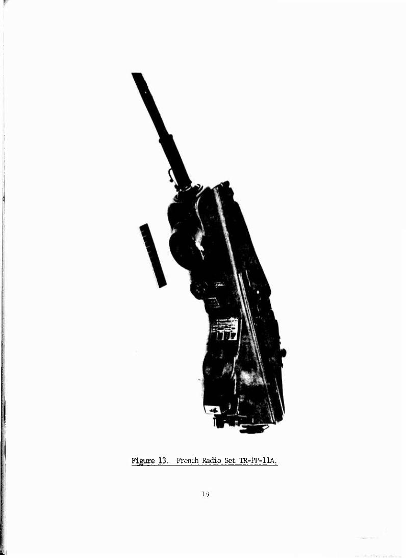
Figure 13. French Radio Set TR-PP-11A.
19
i

'V. General:
1. Frequency Range: ^7 - 55«^ Mc
2. Available Channels: 85 © 100 kc spacing
3. Number of Precet Frequencies: 6
h. Range: 1 mile
5. Dimensions: 12 1/2" X 5 3/l6" X 3"
6. Weight: h pounds 9 ounces
B. Receiver:
1. Sensitivity: O.h microvolts
2. Power Drain: 11 Ma @ 1.5 volts (.017 watts)
: 12 Ma @ 15 volts (.180 watts)
C. Transmitter:
1. Power Output: 250 milliwatts
2. Type of Modulation: Voice, FM, 10 kc deviation
3. Power Drain: 130 Ma P 1.5 v^lts (,20 watts)
150 Ma (5 15 volts (I.65 watts)
Figure 14. Technical characteristics of Radio Set TR-PP-11A.
20

resulted in a piece of equipment that was too large, too heavy, and too
costly for its prime mission. A descriotion of its technical characteristics
is given in Figure 16. The estimated Droduction cost of this ecuipment
was $1,500 to $2,000 a unit. Today, its probable cost per mit, based on the
current price of the PRC-77, would be about $500. The AN/PRC-35 marked the
end of the search for a replacement for the AN/PRC-6, essentially a search
for replacing the SCR-536 as a means of cotrpany-platoon connunications.
12. DEVELDPMaTT OF RADIO RECEIVER FOR INDIVIDUAL RIFIiMAN
Another search, however, one for directing individual riflemen by
equipping each one with a radio receiver, had begun as early as World War II.
This search and interest had been spurred by problems encountered during the
Korean Conflict. In July 1952, the Baker Electronics and Coimunication
Mission to Korea (BEACON Mission) in its final report recommended that a
sinple low-power receiver be provided to squad raenbers. In addition, the
final report of Project VISTA recoranended that a better means of
connunications be provided to individuals during combat. During this time,
the Armored Center had also expressed a need for a helmet-mounted
transmitter-receiver with about a 100-yard range to be used by a tank
platoon leader. Consequently, as a result of BEACON Mission and VISTA
reports, the Office of the Chief of Anry Field Forces prepared military
characteristics for a "radio receiver for individual riflemen," specifying
range, size, and weight. The range was to be the perimeter of the squad
when the receiver was used with the AN/PRC-i5. The set was to be 8 cubic
inches, weigh cne pound, and have a battery life conmensurate with the size
and weight of the battery.
It must be understood that the Sigial Corps Qigineering Laboratories
had periodically investigated the feasibility of developing equipment which
would satisfy both the infantry and amor requirements. Experimental radios 21
-

n i
s
2P
■ . ■■..:..>;L.J1*.»..'..^

A. General;
1. Frequency Range: 30 - 69-95 Mc
2. Available Channels; 800 © 50 kc spacing (all supplied by Internal
synthesizer.)
3. Number of Preset Frequenftles: U
k. Range; 1 mile
5. Dimensions: 11" x 6 3/8" x 3 3/V'
6. Weight: 9*5 pounds
B. Receiver:
1. Sensitivity: 0.U microvolts
2. Power Drain: 56 Ma © 11.7 volts (.66 watts)
7.3 Ma @ 26 volts (.19 watts)
C. Trancmitter:
1. Power Output: 350 - 600 Milliwatts
2. Type of Modulation; Voice, FM, 10 Ice deviation
3. Power Drain; 71 Ma (5 11,7 volts (.83 watts)
120 Ma (? 26 volts (3.13 watts)
Figure 16. Technical characteristics of Radio Set AN/PRC-35.
23
. .. ■ . .
incorporating miniature and sub-miniature tubes proved too large and their
power consunption too great for them to be carried by individual soldiers
without seriously conpromising the soldiers' conbat effectiveness.
13. SEARCH FOR A HELMET RADIO
In late 1953, the Laboratories initiated a full-scale investigation of
the feasibility of installing radio equipment in helmets. Small cocnnercial
transistorized receivers and receiver-transmitters were installed in
conposition helmets, and coimunication over a range of 200 yards was
established with Radio Sets AN/PRC-6 and -10. As a result of this, the
laboratories received work directive CE-29-R to investigate further means
of "improving portability of small radio sets by the conbat soldier." The
directive went on to state that a soldier's primary weapon was his rifle and
that he should be able to keep it in the ready position while carrying out
radio comnunication. The arrangement of radio and rifle as separate items,
each requiring individual use of the hands, was inconsistent with v*at was
desired. CE-29-R suggested that two methods of mounting the squad radio
should be investigated: either attaching it to the stock of a rifle or
fitting it inside a helmet liner. Finally, the work directive concluded by
stating that the radio be designed for automatic assenbly so that it could
be treated as an expendable item.
To investigate one of the alternatives, that of cotrbining radio and
stock of the rifle, RCA developed a receiver which was built into the stock.
But the radio proved awkward to use unless the rifle was in the firing
position. The other alternative proposed by the vrork directive, that of
mounting the radio set inside a helmet, was then investigated. One advant-
age of this, of course, was that the helmet could be used to protect the
electronic circuitry and thus reduce the required weight of the transceiver-
2U
.....

transmitter. But It was also discovered that the shape of the helmet,
designed to fit the form of the rifleman's head, allowed no room for mount-
ing electronic circuitry. An attempt was then made to mount the set in the
apex of the helmet, but this only raised the helmet's center of gravity,
causing the helmet to topple from the head. Outside of the apex, there was
not sufficient space within a standard helmet or liner to momt a receiver-
transmitter.
The only solution, then, was to create a plastic helmet especially to
acconmodate the set (Figure 17). In this model, components of the set were
motnted at the base and underside of the helmet: the receiver-transmitter at
one side and the battery, earpiece, volune control, and on-off switch at the
other. The set, with its antenna built into the helmet, had a range of 300
yards between like equipment and 500 yards between it and FRC-6's or -10's.
14. OCNCEPT TEST OF HEt^ET RADIOS
In July 1955, the Signal Corps Engineering laboratories proposed that
large nmber of helmet radios be procured and given a concept test by a full
division. The Chief Signal Officer repeated this proposal to hi^ier head-
quarters , but was informed that the Continental Amy Command (OCNARC) had
"no requirement" for this item. However, LG James M. Gavin became personally
interested in the project and, in late 1955, decided to proceed with a large-
scale test of helmet-radios at a division level.
The project had to be coordinated with the Quartermaster General
because incorporating the squad radio in the helmet would involve altering
the shape of the helmet. At this time, the Quartermaster Development
laboratories had been experimenting with plastic and fiberglass helmets, and
it was thought possible that a suitable ballistic-resistant non-metallic
helmet might be available for use with the radio set.
25
; i.-.'-.- -
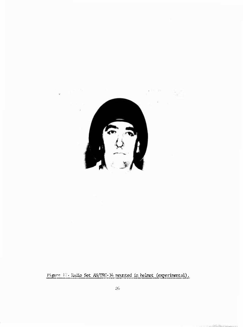
Figure li. Radio Set AN/PRC-34 mounted in helmet (experimental)

Against this backgromd, a contract was placed with RCA In June 1950
to design and fabricate 1600 Radio Sets AN/PRC-34 to be mounted in helmets
and 1000 Radio Sets AN/PRC-36 to be worn on belts. Both sets were to use
the basic circuitry and layout developed by the Signal Corps Engineering
Laboratories and both were to be used to test, evaluate, and develop the
concept of the squad radio. In 1959, all the equipment was delivered.
Figures 18 and 19 show these experimental sets as worn by operators. The
technical characteristics of both sets are given In Figure 20.
15. FIELD TESTS OF HEIMEr RADIOS
In 1959 and 1960, the lOlst Airborne Division, O0NARC, and the Conbat
Development Electronics Conmand (CDEC) carried out field tests of the sets,
with the same equipment going to the other military services and the
Canadian Amy for cocment. Essentially, the concents vMch came back were
that:
1. The radio set inproved the conbat efficiency of the
Individual soldier.
2. The logistical problems associated with this equipment
were realistic, with the exception of the Initial cost.
3. Only a receiver was needed for the Individual riflemen.
4. The cords associated with the AN/PRC-36 tangled in the
underbrush, making this equipment unsuitable for field use.
The concept test of the equipment took the form of a troop test,
carried out by the 101st Airborne Division at Fort Canpbell, Kentucky. The
testing showed that using the radio facilitated and expedited the
transmission of orders and information, contributed significantly to small
mit effectiveness, and enabled die Individual soldier to display Increased
Initiative. As a result, the 101st Airborne reconmended that the concept
27
- x*-f-f»

Figure 18. Radio Set AN/PRC-34 (developnEnt model). Overall view shewing " operator using microphone. '
28
.. .

Figure 19. Radio Sat AN/PRC-36 (developmen*: model). Overall view shou-ing „ antenna lounted on lielmct liner and operator usinp tone button
29

A. General:
1. Frequency Range AN/PRC-34 38 - 38.8 Mc
47.8-51.0 Mc
AN/PRC-36 47.8-51.0 Nfc
2. Available Channels: One of 12 factory preset. Frequency change by
exchange of R. F. and transmitter nüdules.
3. Range: PRC-34 350 yards antenna restrained
500 yards antenna extended
PRC-36 600 yards
4. Dimensions: 4 9/16" x 2 7/8" x 3/4" (Receiver-Transmitter Unit)
5. Weight: PRC-34 3 1/2 pounds Incl Helmet
PRC-36 2 3/4 pounds Incl Battery
B. Receiver
1. Sensitivity: 3 microvolts
2. Power Drain: 8 Ma (? 1.5 volts (.012 watts) ) ) .072 watts
13 Ma Ö 4.5 volts (.060 watts) )
C. Transmitter:
1. Pcx^r Output: 50 milliwatts
2. Type of Modulation: Voice, FM, 15 kc deviation
3. Power Drain: 8 Ma Q 1.5 volts (.012 watts) ) )
13 Ma p 4.5 volts (.060 watts) ) .612 watts )
12 Ma 6 45 volts (.540 watts) )
Figure 20^Technical characteristics of Radio Sets AN/PRC-34 and AN/PRC-36.
3C
_ . - ;

of an individual soldier's radio be approved for use by the Any Tactical
units. Although the models used for the concept test were not suitable In
their existing form, it was felt that the noise-free control obtained while
using the PRC-34,s and PRC-Sö's at unit level justified the continued
research toward the development of an acceptable model of squad radio.
16. USING MICRCTODUIES FOR RADIO EQUIFMElTr
While the results of the concept test were being analyzed, the Signal
Corps Engineering Laboratories were In the midst of a study to determine the
technical feasibility of using nrLcronodules for coranunications equipment.
So, it seemed only logical to use the radio for Individual rifleman as a
vehicle for demonstrating the potential reduction in size and weight of
radios that could be achieved with this new assarbly technique. In addition,
micromodules were being designed for automatic assenbly and thus gave
promise that they could be produced in great quantity at lew cost.
17. FINAL DESIGN OF THE SQUAD RADIO
When it came to deciding the specific form to be used for the squad
radio, several configurations were considered. In the end, it was decided
to separate the receiver and transmitter and to adopt one simple design,
which would make possible maximun output and save costs when automated
production methods were used. Once this basic concept of separating receiver
and transmitter had been agreed upon, the way was then open for various
refinements in design. In the firs:: place, the receiver could now be mounted
on the outside of the steel helmet, and the success of the radio's design
would not hove to depend on a suitable ballistic-resistant plastic helmet
being developed. Secondly, moulting the receiver on the outside of the
helmet, with one earpiece projecting under the rim of the helmet, would
enable an operator to monitor his receiver continuously without vising his
31
-—..,■ mmmmm
hands and so rencve a cause of ear blockage, as was the case with the
PRC-3A;and do away with die cordage which inevitably entangled itself in the
underbrush, as was the case with the AN/PR.C-36. Thirdly, it was reasoned
that the transiritter could be stored in the pocket or clipped to the
clothing and that it did not have to be in the ready position at all times
since the operator could determine v^ien he wanted to use it.
A meeting held at USCONARC headquarters to discuss the proposed form
factors for the new helmet radio ended with the conferees satisfied with
the factors presented and deciding to send the QMR for that equipment back
to the infantry so that the equipment could be modified in accordance with
the QMR change. A proposed QMR for a lightweight radio transmitter and
receiver was received by the Signal Corps Engineering Laboratories in
January 1961. Its salient features are listed in Figure 21..
18. OBJECTIONS TO OOM^ERCIAL EQUIPMEOT
The various agencies that would use this equipment indicated strongly
that the cost of the final helmet radios produced had to be low in order for
the sets to be econcmically feasible in the quantities required. A cost of
50 dollars for the receiver and 75 dollars for the transmitter was considered
maximum. Mention was made of available miniature conmercial broadcast
receivers that cost as little as 10 to 25 dollars, but the agencies raised
various objections. One of these was that the conmercial equipment would
not operate reliably over an extended period of time in a military environ-
ment. Another was that these sets worked against several kilowatt
transmitters with elevated antennas. Therefore, changes in performance of
as much as 10:1 from one set to the next and fron one day to the next were
not as critical as when thpsc sets would be operating against low pcwer
equinrent with limited antennas where calculated path loss would not leave a
]2
. . ■ . .-.

20 January 1961
Salient Features
1. Separate transmitter and receiver
2. Weight less than one pomd (R & T total)
3. Two diamei transmitter
4. 500 meters transmitter/receiver range
5. One mile netted with AN/PRC-25
6. 55 channels
7. Compatible with VRC-12 & PRC-25
8. Transmitter and Receiver Intended for squad leaders, team leaders,
and weapon crew chiefs. (rec issued to selected rifle squad and weapon
crew meobers)
9. Receiver attachable to standard steel helmet
10. TransraLtter carried In pocket
11. Battery life 24 hours
12. Tone signaling required
13. One receiver earphone - not against ear
14. Receiver Squelch required
15. Equipment required not later than FY 64
Figure 211 Proposed $1R for a lightweight radio transmitter and receiver.
33
.
significant margin. In addition, the quantities required for the potential
military market even for this equipment would not approach those required
for the cormercial market. A developmental manufacturer had stated that it
would not pay him to design, set up, and program automation equipment for
less than one million units per year. In light of these objections, it was
proposed to the Office of the Chief Signal Officer (OCSIGO) that a program
be initiated to procure equipment which the manufacturer would warrant to
meet stated field performance requirements for 6 months to one year. No
other requirement would be imposed. In July 1961, OCSIGO directed SCEL to
proceed with the necessary documentation to carry this out.
19. MAJOR CHANGE IN THE QUALITATIVE M/YIEPIL REQUIREMEOT (QMR)
Under this proposed approach, several commercial corporations became
interested in supplying equipment to meet the infantry's need for intra-squad
radios. Some of these companies presented preliminary mockups and experi-
mental models of the proposed equipment, some of which came reasonably close
to maeting the gross requirements. The Laboratories then proceeded to
request quotation for the equipment, but just before they could carry this
out, they received word of a major change in the QMR.
The new requirement stated that the equipment had to be replacement for
the PRC-6 as well as performing as an intra-squad radio. The old C^R was
withdrawn, and a proposed new one was issued for conment. The major
changes proposed are listed in Figure 22.
The Laboratories stated that the required weights were considered
unrealistic and that the conmercial approach was not considered feasible for
the new requirements. Performance over a range of one mile with the allow-
able antenna systems would require the ultimate in performance from available
components, with no allowance made for variation over tenperature or with
3''
.

1. Range - one ndle on channel 1
500 meters on channel 2
(both between conpanion equipment not PRC-25)
2. 90 to 110 possible channels
3. Conpatability with PRC-25, VRC-12, PRC-6 deslied
4. Must serve as replacement for FRC-6
5. Receiver wearable in pocket as well as helmet
6. No external squelch adjustment on receiver
a. (squelch on/off sw allowed)
b. squelch should be ccopatlble with PRC-25
7. Receiver weight 6 to 8 ounces
8. Transmitter wei^t 8 to 10 ounces
9. Battery type coranon to receiver and transmitter
a. Battery life 72 hours desired
b. 1:24 Trans - Rec ratio
10. Priority of Characteristics
a. Range
b. Two preset channels
c. Size and weight
d. Cost
e. Battery life
11. Use of proven conventional, military or coamercially
acceptable electronic parts.
Figure 22. Major changes In previously proposed CMR.
35
■
,

time. Consequently, efforts toward obtaining a conrnercial intra-squad
radio were ended, and the equipment specification was rewritten, requiring
the use of approved military parts, materials, and processes.
20. SCEL RECEIVES FINAL APPROVED gjR
In May 1962, SCEL received the approved QMR and was directed to
initiate an inmediate in-house developnent program as well as place an
external development contract. Figure 23 gives a resume of the major
requirements of the approved final QMR. Looking at Figure 23, it is
interesting to note that under "Priority of Characteristics" "cost" had
dropped from fourth place to seventh place, behind such factors as "reli-
ability" and "channel changeability at second echelon."
21. PROBIÜS WITH FINAL DESIGNS
With the issuance of the final approved tyR for the squad radio,
several designs of receiver and transmitter cases, antennas, and switches
were mocked up for evaluation. Figure 24 shows the various mock-ups of case
designs that were proposed for Radio Receiver AN/PRR-9. Designs for various
types of switches and antennas are showi in Figures 25, 26, and 27. Switches,
always a difficult problem, proved especially so vhen it came to sealing
them. Push-to-talk switches, for instances, were notably bad in this
respect. One solution which did not work out in practice was the use of
magietic reed switches actuated by permanent magnets sliding on the outside
of the case. It did not work out because the resultant switches were too
large and the tolerance problem too difficult to handle. Similar
difficulties were encountered in the transmitter antenna. Figures 25 , 26 .
and 27 show some of the solutions proposed, ranging from folding antennas
(Figure 25) to telescopic antennas (Figures 26 , 27). Figure 26 shews a
ncck-up of the AN/PRT-A with flexible telescopic antenna having a spring-
36
.

Dated: 10 May 1962
Resxme of major reguiranents
1. Range: 500 meters and 1 mile between conpanlon equipment
2. Weight: 30 ounces total
Receiver: 6 to 10 ounces
Transmitter: 10 to 20 ounces
3. Channels:
a. Single channel receiver
b. TWo channel transmitter
c. 80 to 110 channels possible
4. Should be conpatible with VRC-12 and PRC-25
Must be compatible with AN/PRC-6
5. Voice and tone provision
6. Collapsible transmitter antenna, sufficiently pliable to ndnlndze
breaking
7. Receiver ear plug and cord required
8. Degraded performance acceptable when not mounted on helmet
9. Priority of Characteristics
a. Range
b. Two channel transmitter
c. Size, weight, and configuration
d. Durability and reliability
e. Battery life
f. Channel changeability at second echelon
g. Cost
Figure 23. Approved final flR for intra-squad radio.

Figure 2h. Various mock-ups of case designs E£°P2i!£i| ^or Rgjio Receiver AN/PRR-9.

bfeck-up of Radio Transmitter AN/PRT-4 showing proposed lanynrd
39
;

Figure 26. Mack-up of Radio Transnltter AN/PRT-4 shovdiig flexibility of telescopic antenna wr'.th spring-loaded bead base!
1*0

Figure 27. Mock-up of Radio Transmtter AN/PPI-4 shewing telescopic antenna with ball swivel base (collapsed).
hi

loaded bead base. Although some trouble with the antenna was reported in
the S/T report, no major difficulty with it was encountered, and it was
expected that this design could be Improved soma^at for the production
models. Figure 24 shews another attaipt at solving the problem by providing
a ball swivel joint at the base of the antenna. Both designs added serious
electrical problems by increasing antenna base capacitance.
Problems were also encountered in trying to reduce the weight of the
transmitter by eliminating the battery box and attaching the battery with
an elastic strap. This is shown in Figure 28. Another proposal for hold-
ing the battery in place is shewn in Figure 29. Ihis involved using an
adjustable strap to hold the battery in place. After both proposals were
evaluated, it was decided that a battery case was needed to provide a
reasonable ground plane for the antenna.
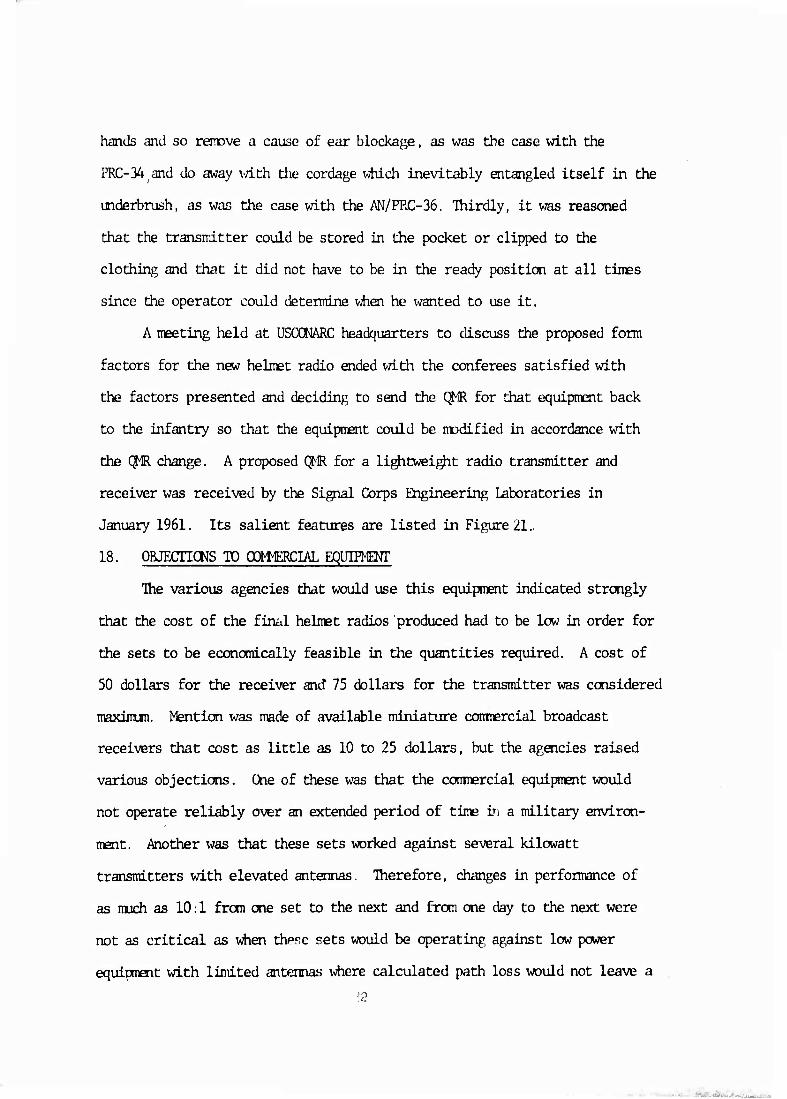
After many of the problems with the size of receiver and transmitter
-.ases, types of antennas and switches, and batteries had been resolved,
the first working laboratory models of the receiver and transmitter were
produced. These are shown in Figure 30. The receiver weighed 10.5 ounces
and the transmitter 23 ounces, both exceeding the QMR. However, the models
did perform satisfactorily over a one-mile test range, demonstrating the
feasibility of the stated requirements. In spite of this, Fort Benning
remained dissatisfied with the size and length of both and requested a
demonstration of other sizes and shapes. After nuch experimentation, a
final laboratory model (Figure '31) was produced which demonstrated the.
ultimate that was possible in reducing transmitter and receiver to their
smallest possible sizes with available cenponents.
The transmitter is shown with a small battery container intended for
a magnesium battery. Although Fort Benning found this arrangement
h2

Figure 28. Mock-up of Radio Transmitter AN/PRT-4 showing battery held in position with a proposed elastic strap.
hi

Figure 29. >bck-up of Radio Transmitter AN/PKT-A showinp. adiustaMp
""'" ~" battery strap. i.i.
Figure 30. Badlo Receiver AN/PRR-9 (XE-1) and Radio Transmitter AN/PRr-4 (XE-1).
H'i

Figure 31. Radio Transmitter AN/PKT-A 'XE-2) and Radio Receiver AN/PRR-9 (XE^iy:
hi.
satisfactory, the battery did not materialize, and a small Le Clanche
battery had to be designed to fit the container. The Laboratory did manage,
however, to reduce the overall length of the transmitter case approximately
one inch. A detailed and conplete discussion of the internal development of
the AN/PRR-9 and the AN/PKr-4 will be found in this writer's Technical
Report EGCM-aASa.'1
22. OONIBACT PIACED WITH DELOO RADIO
In August 1962, a contract was placed with the Delco Radio Division of
General Motors Corporation for 66 receivers and 41 transmitters, Fifty
receivers and 25 transmitters were slated for engineering and service tests,
6 were to be used by the Quartermaster for studies of the equipment's
conpatibility with all types of clothing, and 10 were for experimental use
and demonstration. The equipment resulting from this contract is shown in
Figure 37 and 38.
The final model of the transmitter had a short battery container and
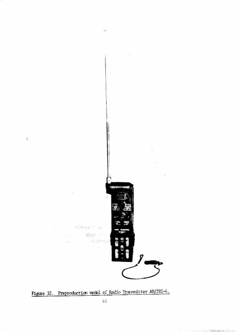
appears in Figure 32; the final model of the receiver is shown in Figure 33.
For the latter, the contractor was able to develop a very efficient audio
horn.
The final technical characteristics of both transmitter and receiver are
presented in Figure 34.
23. OTHER nag REQUIRED CN DELOO RADIO OCNIRACT
Also required on this contract were an alignment Jig, crystal mit sets,
a radio test set, and a battery test set. The alignment Jig with all of its
signal sources, meters, and tools necessary for the alignment of receiver and
transmitter is shown in Figure 35.
The final models of the receiver and transmitter used identical but
separate crystals. For the service test, each crystal kit (Figure 36)
contained 110 crystals, but the production units contained only 100. The
ratio of crystal sets to the mnfcer of pieces of equipment was not determined.
Curtis, M.W. "ÜSAEL Internal Development of Radio Receiver AN/PRR-9 and Radio Radio Transmitter AN/PRT-4." Technical Report EOQM-2482. Septenber 1964.
hi
. ■
I;
■ '
Figure 32. Preproduction nodel of Radio Transmitter AN/PKI-A.
1+8

, 'i' - i: s
¥
Figure 33. Preproduction model of Radio Receiver AN/PRR-9.
U9
■
■

A. General:
1. Frequency Range: 47 - 57 Mc
2. Available Channels: 200 (5 50 kc spacing (100 crystals provided)
3. Range: 1600 meters (1 niile) on ki^i transmitter power.
500 meters on low transmitter power.
B. Receiver:
1. Sensitivity: 0.5 microvolts
2. Nunber of Preset Frequencies: 1
3. Power Drain: 13 Ma @ 5 volts w/o signal input (.065 watts)
25 Ma ^ 5 volts with signal input (. 125 watts)
A. Diirensions: 6 1/2" x 3" x 1 1/8"
5. Weight: 8.6 ounces
C. Transmitter:
1. Power Output: 500 milliwatts on channel 1
50 milliwatts on channel 2
2. Nunber of Preset Frequencies: 2
3. Type of Modulation: Voice or tone, PM, 8 kc deviation.
4. Power Drain: 120 Ma @ 12 volts (1.44 watts)
5. DixiEnsions: 8" x 2 1/4" x 1 1/2" w (XC-1) battery
6 1/2" x 2 1/4" x 1 1/2" w (XE-3) battery
6. Weight: 18 ounces w (XC-1) battery
17 ounces w (XE-3) battery
Figure 3U. Final technical characteristics of Radio Transmitter AN/PRT-4 —ö and Radio Receiver AN/PKR-y.
50
.

:. :^f
• lev« uKMiar
INDICATOR. CHANNEL ALIGNMFNT ID-llfl9( J/fK
•
it-, r«(ct«ou
rUNCTION MCVUAnf»
Flffure 33. Alimment jig for firuil models of Radio Transmitter AN/PRT-A and I^dJo Receiver AN/PRR-9. ,\
,

althou$i estimates of 1; 10 and 1; 25 v;cre nvide, depending on the number of
sets being aligped at a particular service point. The Department of Defense
(DOD) Value Engineering (VE) Office conceded that no more than 50 or 60 were
required, indicating that a substantial savings could be realized by supply-
ing partial kits to some operating units.
DOD's VE Office carried out an exhaustive study, making several
suggestions vhich ranged all the way frcm redesigning the equipment for AM
rather than FM to the use of a boy scout snap on the lanyard rather than the
stock item used on antenna guys. The Delco radio was designed by the same
engineers who designed the company' s corrmercial radios, which were intended
to meet the demands of customers for performance and reliability at an
absolute minimum cost, None of the VE suggestions, however, could be adopted
without sufficiently reducing performance.
Although a radio test set (Figure 37 was required and supplied under
this contract, the actual development of a test set was dropped vÄien it
became evident that the cost of producing it would be excessive. The battery
tester (Figure 38 provided under this contract was built but not developed
under the squad radio program. The round blocks shown in the figure are the
proper leads and metering resistors, vMch are tailored to fit the battery
under test.
24. SERVICE TEST OF TOE SQUAD RADIO
The final models were shipped to AEPG for engineering tests on April
1, 1964. After the tests, the equipment was returned to the Signal Corps
Engineering laboratories for certain changes and checks. A redesigned
electronic chassis was installed in the transmitter, and a check was made of
receiver performance. The sets vere then shipped to Fort Bragg for a
service test on Septenber 15, 1964, with 4 transmitters and receivers going
'33

Figure 3Tj Radio test set for final models of Radio Transmitter AN/PRT-A 'and Radio Receiver AN/PRR-9. "
^t

\
I)
..'
y I ■ßr<' I r ; /. ä .u^iiüi. •-—
■ ■
'3' ■ ' I
■^
I u I o
■Ü
s 1 p.
i 14-1 O
w
I«
4-1
4J 4-)
.3 00
i..
V;

to AEPG for enpincering tests on the new transmitter model XE-6A. Another
6 transmitters and 12 receivers v/ere shipped to AEPG for conpletion of
electrcmagnetic vulnerability and conpatibility tests, and 6 transmitters
and 12 receivers were sent to (DEC for test. A nunber of units also went to
the 7th Arm/ in Europe for demonstration. And to conplete testing, jungle
and desert tests were planned for later in 1964.
25. THE DEVELOPMENT ACCEPTANCE IN PROCESS REVIEW
At the final In Process Review (IPR), a representative of the Combat
Development Conmand (CTJC) stated that CDC did not like the concept of a two-
part helmet radio in which the transmitter was held in the hand and the
receiver was mounted on a helmet. To add to this dissatisfaction, the
Marine Corps had long been clamoring for a single-unit design, such as the
AN/PRC-6.
In reply to CDC, the Department of the Army (DA) representative claimed
that inasmuch as this was the concept called for in the qualitative materiel
requirement, the only way in which the basic idea could be altered wuld be
for CDC to request an official change to the QMR. This CDC diose not to do.
26. PRODUCnCN
Ihe outcome of all this was that fifty squad radios were built to
meet active test requirements in Vietnam, where initial reaction turned out
to be good. As a result, production was increased to 5,000 units, and
subsequent orders raised this amount to more than 25,000 sets.
27. FIELDING
Yet, though initial reaction to the set had been good, its use in
full-scale operations in Vietnam proved disappointing. In the dense,
humid jungles of Southeast Asia, the range of the AN/PRC-77 was reduced to
a few hundred yards and that of the squad radio to a few hundred feet. In
addition, other problems arose. One lay with the difficulty in properly
alibiing the equipment when channels were changed in the fielj. Another with
the battery which disintegrated because to save weight it had purposely been
left unprotected. And still another when operators contrary to the
equipment's capabilities, tried to obtain full range from receivers not
mounted on helmets.
All these difficulties served once again to revive the controversy
over whether the helmet radio should be a single unit or a tw)-part affair.
One conclusion that was reached at this time was that the Arny had no need
to provide individual menbers of squads with radio receivers. Still another
conclusion was that under the harsh necessities of war and because required
quantities of sets had been drastically reduced from 250,000 to 30-40,000
units, extreme low cost in producing this equipment was no longer a primary
objective.
One had the impression at this time that many of the faults ascribed by
users to the helmet radio were really disguised dislike of the two-piece
design of the equipment and the peculiarities of sirall radio operation.
Ihis dislike took the form of finding fault with the equipment and expressed
itself in a vague desire to want something "different." But this is purely
a personal inpression and not meant to suggest that anyone purposely or
willfully condermed the equipment. It was sinply that the potentialities of
the helmet radio on the drawing board had not materialized on the battlefield
and so antagonized acceptance. One has only to read the letter (Appendix I)
recently sent by the 2nd Ranger Battalion of the 75th Infantry to pertinent
organizations to realize that dissatisfaction with squad radios is still with

Uü.
28. CURRtKT STATUS
The fuial chapter of t±ie squad radio is yet to be v/ritten. At this
writing, several thousand sets languish in depots unissued, with the Army
finding it difficult to devise at a reasonable cost requirements for a
modified or new squad radio which will satisfy users. As presently designed,
the conponents of a squad radio cost $107 for the receiver and $139 for the
transmitter.
The Marine Corps' counterpart to the squad radio is the AN/PRC-68, a
one-piece transceiver complete with synthesizer (no crystal banks needed),
but having a much shorter range (one-third to one-half mile) at an estimated
production cost of $1400. In addition to having less range, another of its
disadvantages is that its battery costs four to ten times that of the Army's
radio.
In an attenpt to satisfy users and meet the current requirements for
small unit transceivers (SUT), the Anny is considering using several foreign
radios. Some other sets are also being considered. One is the Marine Corps'
AN/PRC-68 or a version of it that can be modified at low cost. Another is a
repackaged version of the squad radio (the AN/PRC-88, consisting of one
AN/PRR-9 and one AN/PRT-4), a configuration that places the receiver and
transmitter in one hand-held case.
29. THE FUTURE
And this is how matters stand at the present with the squad radio. What
the future will bring remains unclear. At the final IPR, representatives of
users of the set pointed out that the radio did not have to net with larger
manpack and vehicular radios, even though the CJMR stated that it "should."
Even before the first production units had come off the assembly line,
58
users had requested that the radio transmitter be modified by adding a tone
squelch generator tliat ^'jould make the set "fully compatible and interoperable
in all voice modes with larger equipment. Concurrently, a program has been
initiated for a new family of manpack and vehicular equipment with built in
security and anti-janming (AJ) capability, with this capability taking the
form of pseudo random frequency hopping. A new squad radio with features
which would insure conplete conpatibility with this new family of sets vrould
by present engineering estimates be prohibitive in size, weight, cost, and
battery consumption and complex in operation. So present plans call for the
new single channel ground airborne radio system (SINOGARS) to be able to
operate in the nonsecure mode while remaining on a single frequency to assure
interoperability with current VHF-FK tactical manpack and vehicular
equipment. Ihis, at least, would provide a degree of conpatibility with
practical squad radios or small unit transceivers that the state of the art
could support. But, in the last analysis, only tiine/technology, and the
representatives of future users will determine the future of the squad radio.
59
Appendix I Letter sent by 2nd Ranger Battalion en Field Testing of Squad Radios
Page 1
ROUTINE
PT 00057 336/0312Z
:CSA:PH:Tr:SCA:GS:HI:MM:PP:PT:CP:SS:m:RD:CE:ST:PA:AD:IO:LB:TL:PL:
ACT
INFO:
RATUZYUH RUCLAIA1732 3352151-UUU-RUEDBIA. ZURUUUUU R 012108Z DEC 75 m CDR TRADOC FT MUROE VA / /OCSCO// INFO RUEADWD/HQ DA WASHDC //DAMA-CSC// RUEEHIA/CDR ECCM FT MDNMDUIH NJ //AMSEL-NL// REUDHIA/CDR AMC ALEX VA//AM3©-SI// R 252207Z NOV 75 EM CDR 9TH INF DIV & FT IJEWIS WA //AFZH-DPIPO// TO CDR FORSO0M FT M^WRSON GA //AZCE// INFO CDR TRADOC FT MDNRDE VA //ATCD-SC-E// CDR USA ARMY INF CtN FT HENNING GA //ATZB-CD-MS-E// CDR 1ST BN (RANGER) 75TH INF FT STEWART GA //AKR-IL-CE// BT UNCLAS SUBJ: SQUAD RADIOS 1. THE 20 BN (RGR) 75™ INF HAS FOUND THE SQUAD RADIOS. AN/PRT-A AND AN/PRR-9 TO BE INADEQUATE FOR RANGER OPERATIONS. IWENSIVE FIEID TRAINING HAS PROVED THE RADIO TO BE INOOMPATIBLF. W™ ^^^ OF OPERATIONS AND MMMENT TECHNIQUES QIPIJOYED BY RANGER UNITS. THE SUCCESS OF RANGER OPERATIONS DEPENDS ON THE ABILITY OF THE PLATOON LEADER TO EFFECTIVELY CCNTRDL HIS SUBORDINATES AND THE LACK OF
60
MWimoiiii|.iw«
Appendix I Letter sent by 2nd Ranger Battalion on Field Testing of gq^jg j Radios
Page 2
PAGE 2 RUBLAIA1732 UNCLAS COMUNICAnONS HINDERS HIS CONTROL. IT IS URGENT 1HAT A RELIABLE PLATOON COMAND NET RADIO BE ISSUED RANSER BATTALIONS IN ORDER TO ACCOMPLISH ASSIGNED MISSIONS. 2. THE 1ST BN (RANGER) 75TH ENCOUNIERED SIMILAR CCmiNICATIONS PROBLEMS WITH THE SQUAD RADIOS. TRADOC CONCURRED IN THE DEFICIENCY OF THE RADIOS (MESSAGE ATCD-SC-E, 271926Z NOV 74. SUBJ: TEST OF RADIO SET AN/URC-68 .) THE URC-68 RADIOS WERE ISSUED: HCWEVER, REPAIR PARTS ARE NOT READILY AVAIIABIE AND MAINENANCE SUPPORT POSES A SERIOUS PROBLEM. THE RANGER BATTALIONS FEEL THAT THE AN/URC-68 IS NOT THE SOLUTION TO THE PROBIiK. 3. COORDINAnON HAS BEEN MADE WITH TRADOC AND THE INFANIRY SCHOOL C-E REPRESENEATIVES CONCERNING THE REQUIREMENT FOR A RELIABLE SQUAD RADIO. RADIO SETS AN/PRC-68 AND THE SFM-52 ARE BEING DEVELOPED AS A PLATOON CmmD NET RADIO AND ARE READY FOR FIELD TESTING. THE 2ND BATTALION WOULD PROVIDE AN IDEAL TEST UNIT FOR THESE NEWLY DEVELOPED RADIOS AS VARIOUS CLIMATIC TRAINING IS PROGRAMED FOR THE BATTALION DURING THE 3D AND 4TH QUARTERS OF FY 76. THE BATTALION DESIRES TO ASSIST IN TESTING THE PLATOCN CCMMAND RADIOS AT THE EARLIEST POSSIBIi: DATE BT W173Z
NNNN ROUTINE
61

Appendix II. Supplementary Figures
&
2
i
u2

V
o
$
63
-

Figure S3, ^^a^tter RT- f )/P,r-6 (XC^^dMt^a Al ( )/PRC-6 (AL-Zj. part of Kadio Set mPRC-Z mj) ^tema shov^ ^gg to receiver-f^^nr—^^1-
6k
. ■ . . .

■«SÄ»
ww^.y^i^iWi
Figure s1^. Radio Set AN/PRC-34 (dewloprientnicxiel) Receiver-tninsmitter (less microphone) shewn irpunted in interior of helmet.
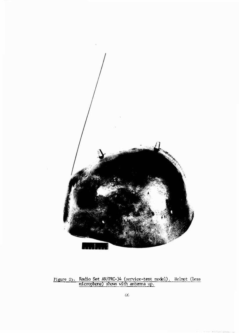
Figure S5. Radio Set AN/PRC-34 (service-test model) microphone) shown with antenna up.
Helmet (less
66
..

Figu.-e s6. Radio Set AN/PRC-36 (deyelopment model). Antenna shown ncunted on radio set and acoustic accessories mounted on standard helmet liner.
67
:> <U«.i£)U^.> I .

■ .'
Figure S7. Developmental model of Radio Transmitter AN/PRT-4.
bfl
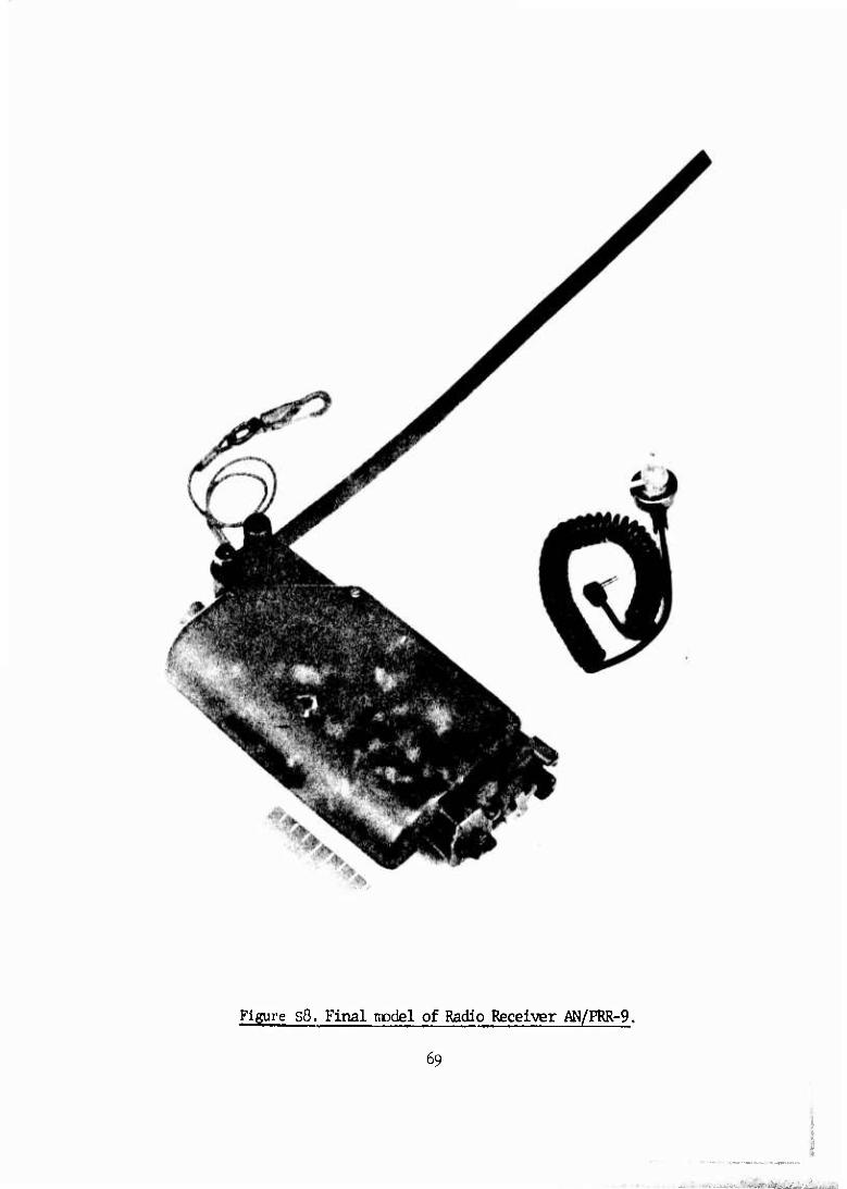
Figure s8. Final model of Radio Receiver AN/PRR-9.
69
.. ..
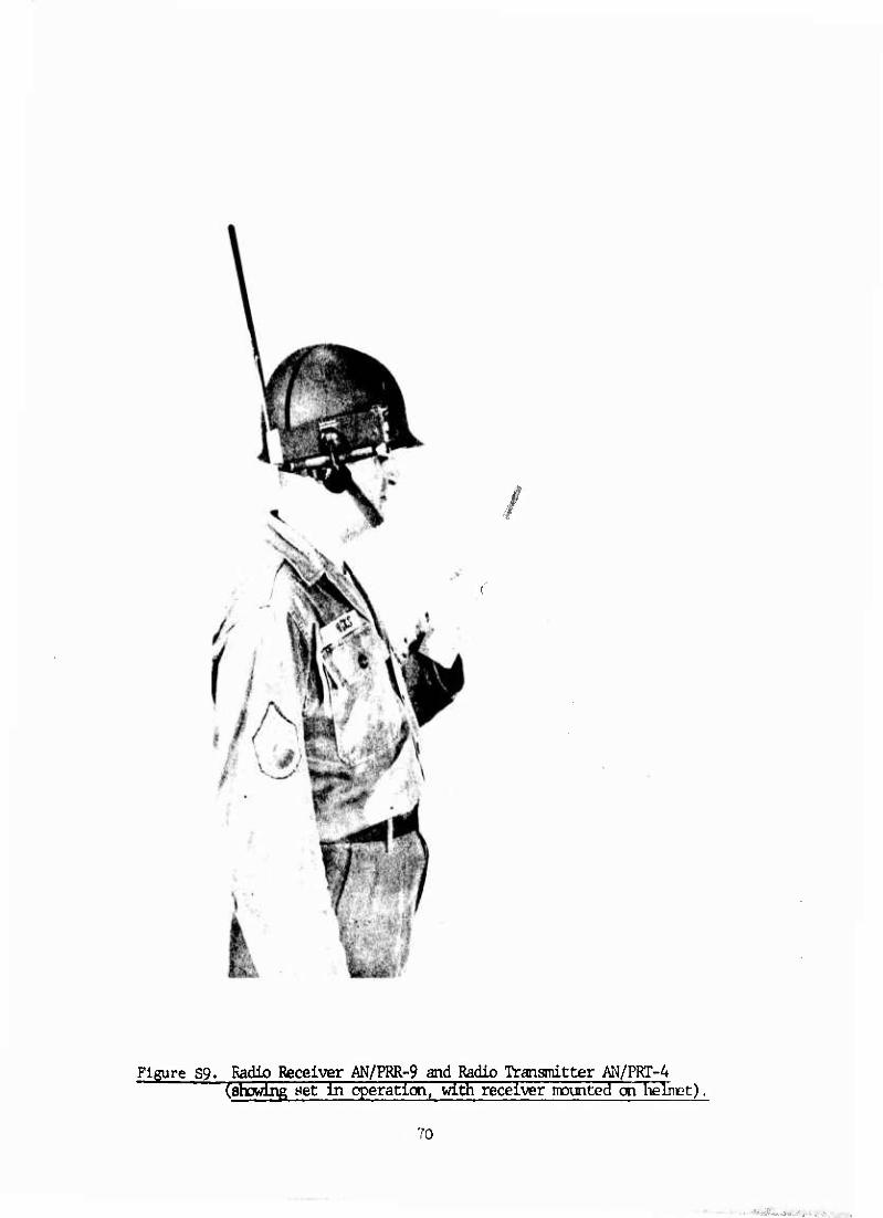
Figure S9. Radio Receiver AN/PRR-9 and Radio Transmitter AN/PKT-A " Cstiowlng set in operation, with receiver mounted on hüimt),
70
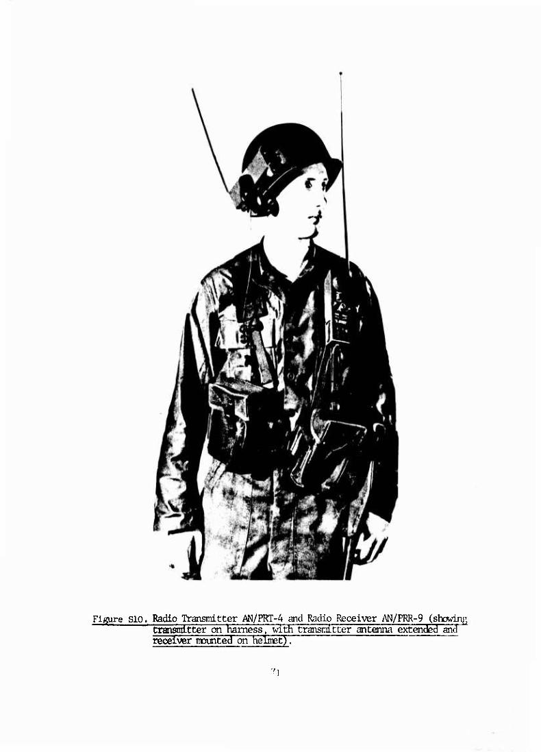
Figure SIO. Radio Transmitter AN/PRT-4 and Radio Receiver AN/PRR-9 (showinp, transmitter on harness, with transmitter antenna extended and receiver mounted on helmetJ"!
71

Figure Sll. Radio transmitter AN/PRT-4 and Radio Receiver AN/PRR-9 (showing receiver and transmitter in operator's pockets, with ear plup, in use).
72
.

Figure S12. Radio transinitter AN/PRT-4 and Radio Receiver AN/PRR-9 (showing transmitter hooked on harness, with antenna collapsed and receiver mounted on lielmet) .

APPENDIX III. SUPPLEMENTARY MEMORANDA
NOTE
The underlining in the letters found in
APPENDIX III ras done by the vriter of
this report to emphasize those aspects
which specifically pertain to the
evolution of the squad radio. Some
sections, however, were deleted to make
the letters suitable as viewgraphs for
presentation at the final In Process s
Review (IPR). The complete originals
were not readily available for this
report.
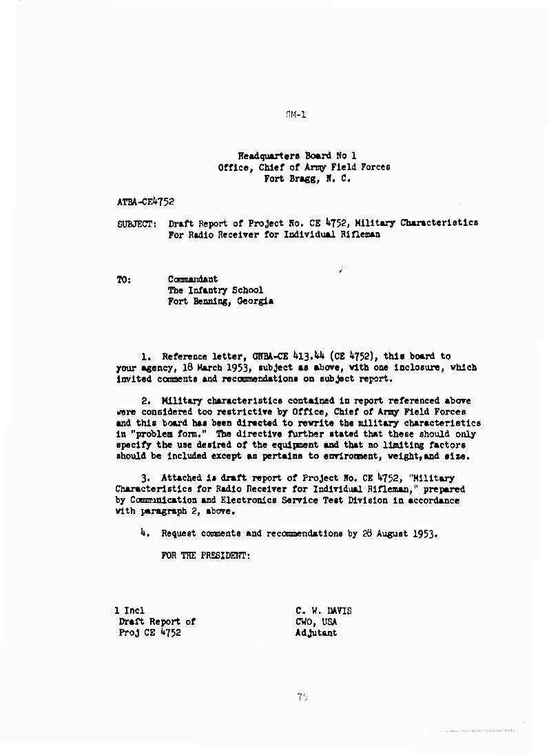
SM-1
Headquarters Board No 1 Office, Chief of Arny Field Forces
Fort Bragg, II. C.
ATBA-CEl*752
SUBJECT: Draft Report of Project Ho. CE U752, Military Characteristics For Radio Receiver for Individual Rifleman
TO: CoraMuidant The Infantry School Fort Bennlng, Georgia
1. Reference letter, ONBA-CE hllM (CE U752), this board to your Agency, 18 March 1953, subject as above, vlth one Inclosure, which invited ccnments and recoomendatlons on subject report.
2. Military characteristics contained in report referenced above rfere considered too restrictive by Office, Chief of Army Field Forces and this board has been directed to rewrite the military characteristics in "problem form." The directive further stated that these should only specify the use desired of the equipment and that no limiting factors should be Included except as pertains to envlroment, weight,and size.
3. Attached is draft report of Project Ho. CE ^752, "Military Characteristic a for Radio Receiver for Individual Rifleman," prepared by Comsunlcation and Electronics Service Test Division in accordance with paragraph 2, above.
h. Request comments and recommendations by 26 August 1953•
FOR THE PRESIDEnT:
1 Incl Draft Report of ProJ CE U752
C. W. DAVIS CWO, USA Adjutant
T'J

SM-2
MEMO FOR RECORD:
B/L G3 kl3.hk (18 Nov 53), ACofS, G3, Operations to OCAFF, dtd l8 Nov 53,
sutj: Miniature'Radio Receiver
1. Ref is made to Appendix I of the 0R0 Dept, "A Study of Combat Com-
munications, Korea, Jan-July 52", 0R0-T-1+3 (FEC), dtd 29 Dec 52.
2. It is rqst that you examine possible rqmts for miniature rad
receivers which can be used in conjunction with current tactical rad sets to
facilitate and extend control within frontline combat units. A commercial
version of such a miniature rad receiver has been developed and can be made
available for evaluation. Thru the use of miniaturized components, incl
transistors, the proposed rad receivers can be produced in the approx size
of a typical rad ear phone used by the USAF. The miniature receivers mipht
then be readily fitted to man's head under a helmet.
3. A similar suggestion for both a miniature rad receiver and
transmitter appears in the ref of para 1 abv. Such equip, however, has not
yet been developed and would undoubtedly be somewhat greater in size than the
proposed earphone receiver. Although the miniature receiver would be design-
ed for simplicity to receive only one preset frequency, the utility to a
platoon, squad, or weapons unit leader under combat conditions might be
immeasurable.
k. If your reply to this query indicates a rqmt for the miniature
radio receivers, it is requested that you specify in detail the usage and
distribution which you propose.
/s/ CD. EDDLEMAN, MaJ Gen, GS, ACofS, G-3
76
. ..

SM-3
ATDEV-5 ^13.^ (18 NOT 53) l»t Ind SUBJECT: Miniature Radio Receiver
Office, Chief of Amy Field Force», Fort Monroe, Virginia 23 Dec 19$3
TO: AsBlstant Chief of Staff, C'-3,Operations, Department of the Aray, Washington 25, D. C.
1. Reference Is made to:
a. Final Report of the Baker Electronics and Communication Mission to Korea, BEACON Mission, July 1952, which recommended on page 16, that a simple low-power receiver be provided squad members.
b. Final Report, Project YISTA, Tolume h. Chapter U, which recommends, under paragraph lib3, that a better means of coamuiica- tion be provided Individuals during combat.
2. It is considered by this Office that the statements by the BEACON Mission and Project VISTA, as well as the Operations Research Organltatlon study, are expressions of military needs and not formal statements of requirements. A requirement for an item of military equipment is formally established only after thorough consideration is given to its operational and logistical role in the battlefield environment. This consideration Includes its envisaged cost, complex- ity and the competence requirements for maintenance and operator personnel.
3« .OPJJJ-April 1952, Board Ho 1, OCAFF, was directed to study the requirement for, a radio receiver for individual rifleman. This study and subsequent coordination with Interested agencies, including Zone of Interior Amies and the Signal Corps Engineering Laboratories have encompassed most of the factors cited aa requirement considerations in paragraph 2.
k. However, dug to the lack of factual field experience, the 0Pe_rfl^.1_?n*lJ"0!*. 9f Bubject equipment in the battlefield environment fcpQta logistical impllcationa has not been determined. Therefox*, a specific requirement for a miniature radio receiver for the individual rifleman can not be established at this tiae.
5. In order to validate current concepts and information, it is jplannedthat a field evaluation be conducted by a T/ofcE rifle [company equipped with varlouBdlBtrlbutlonB of the conmerclslmlnia- 'ture radio receiver's cited in iMÜigräph 2 of the basic letter.
^ If the field evaluation results in a definite statement, °L.!?^!!'TOai^Ac!L^.^l-^fpVy*rd^ to your office at the earliest possible date.
7. It is requested that this Office be furnished with detailed information as to availability, cost, and characterlBtico of the commercial miniature radio receivers, in order that qualitative requirements may be determined for the field evaluation.
FOR THE CHIEF OF AFMY FIELD FORCES:
77
.

SM-14
C-3 Plans Headquarters, The_ Ampred Center
Fort Knox, Kentucky
AIDIT h20 1^ December 1951+
SUBJECT: Tank Helmet Radio
10: Chief, Signal Corps Engineering Laboratories Fort Monmouth, New Jersey
1. It Is believed that the effectiveness of a.tank platoonJLeader_ could be substantially enhanced if he vere provided with communications .which would alvays keep hlo In contact vlth his coamand tank. It Is visualized that a helmet with a transmitter-receiver built-in, having an effective range of approximately 100 yards, netted with a elmllar trans- mitter-receiver within the tank, which in turn could feed into the present radio would jjenalt the platoon leader to bettei^jaerform the personal reconnaissance on foot, that is part of proper technique of 'cdnmänding a tank platoon, and still retain control. All too often there is a reluctance to dismount and walk to the crest of a hill, or reconnoitcr a questionable piece of ground for trafficabllity, because this action requires disconnecting from the radio equipment and Interrupts his command and control of his unit. Also, such a device would facilitate contact with the small unit tank leader who may be dismounted, for example, conferring with the accompanylpg Infantry leader in a covered and concealed position. A PRC-6 of current design does not fulfill the requirements because of it could not be used both in and outside the tank. Tn addition, It requires use of hands which prevents the platoon leader, from using a map or binoculars or from performing other tasks simultaneously.
2. If by use of printed currents in a laminated nylon helmet the cost could be reduced sufficiently, such a helmet radio netted with the platoon command channel would be of great use to every tank conmandcr. It would place him in constant communications with his tank and would be useful, for example, in leading his tank into a covered and concealed firing position or into a bivouac area at night. Such a unit should be self-contained with no outside power connections necessary, which should be possible through the use of printed circuits and transistors to reduce cost and power requirements. Power could be supplied by a battery con- toured to fit the front or back surface of the helmet.
/a/ ROLIJII T. STKItJET; Lt Colonel, Gi5 78
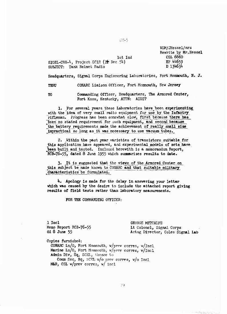
SM-5
let Ind SIGEL-CRB-U, Project CC1R (l+ Dec 5k) SUBJECT: Tank Helmet Radio
WSM/JHessel/ru-B Revrrite by Mr.Hessel
CSL 6660 HP M*659 D 13^63^
Headquarters, Signal Corps Engineering Laboratories, Fort Monnouth, N. J.
THRU CONARC Liaison Officer, Fort Monnouth, Hew Jersey
TO Coramanding Officer, Headquarters, The Armored Center, Fort Knox, Kentucky, ATTN: AIDIT
1. For several years these Laboratories have been experimenting with the "idea of very Rmall radio equipment for use by the Infantry rifleman. Progress has been somewhat slow, first because there has been no stated requirement for euch equipment, a^^econdbecau8e_
3he battery requirements made the achievement of really small size impractical so long as it was necessary to use vacuum tubes.
2. Within the past year varieties of translBtorB suitable^for this application have appeared, and experimental models of sets have
Jaeen built and tested. Inclosed herewith is a memorandum Report, RCB-76-55, dated 8 June 1955 which sumtnarlzes results to date.
3. It is suggested that the views of the Armored Center on this^ subject be made known to CONARC and that suitable military
^characteristics be formulated.
h. Apology is made for the delay in answering your letter which was caused by the desire to Include the attached report giving results of field tests rather than laboratory measurements.
FOR THE COMMANDING OFFICER:
1 Incl Memo Report RCB-76-55 dd 8 June 55
GEORGE METCAI-FE Lt Colonel, Signal Corps Actng Director, Coles Signal Lab
Copies furnished: COHARC Ln/O, Fort Monmouth, w/prcv corres, w/lncl Marine Ln/O, Fort Monmouth, w/prev corres, w/lncl Admin Dlv, Hq, SCHI,, thence to
Coram Sec, Hq, SCSL w/o prcv corren, w/o Incl M&R, CSL w/prev corres, w/ incl
Y9

m-i
COLES SIGNAL LABORATORY, SCEL RADIO COMMUNICATION BRANCH
FORT MONMOUTH, NEW JERSEY
SIGEL-CRBA RCB-75-55 IToJect 801R 8 Juna 55
MEMORANDUM REPORT
MEMORANDUM TO: Chief, Radio Communication Branch, CSL
SUBJECT: CommunicatlonB Equipment for Forward Area Combat Personnel
1. PURPOSE; This memorandum covers the results of a preliminary Investigation to determine the feasibility of communication with small radio e^uipnents installed In composition helmets.
2. CONCLUSIONS; It is concluded tlmt:
a. It is feasible to Install In a composition helmet a radio set which will provide about 200 yards communication range.
b. The standard composition helmet design is not suitable. It will be necessary to provide space In the form of bulges at either side of the helmet for the radio equipnent. The outer surface of the proposed radio helmet should be contoured to closely resemble that of the standard helmet so as not to reveal the presence of radio equipment.
c. The equipment described can be materially improved by reducing regenerative tendencies, increasing sensitivity of the re- ceivers, better limiting, and providing more audio output.
3. RECOMMENDATIONS; In the event that this project is con- tinued, it is recommended that the following be accomplished;
a. Design a new radio set which would Include the fore- going modifications and which would Baticfy military environmental requirements.
b. Procure compoGltion helmets contoured to provide mounting facilities for the radio equipnent.
m
■ .. ■ ..,..•.' . .

SM-7 GCE-R SUBJECT: Work Directive CE-29 R
L. Purpose of Project and Coramente:
1, This Investigation is for the purpose of study and experiment^ on varies meeE^o^imp^ovlng the portability of small radio sets by th^cpmbat~soidlerT Fighting effectiveness is compromised by any equipment or mission which the soldier cannot easily combine with bis offensive operations.
2. JThe soldier's primary weapon Is his rifle. He should be able to keep his rifle In ready position whilej?erforming necesBar,yj:adio_ communication. The present provision of rifle and radio aa separate Items, each requiring use of the hands, is inconsistent with the desire^ situation.
3. We are aware of numerous ideas for affixing the radio to the wearer. Radio Set SCR-511, Intended for the horse-mounted cavalryman, is an example of the idea of adapting the package to the user's mission. Other suggestions have received less attention.
k. It is requested that your Laboratories investigate the problem outlined above.
a. .ItJLsdeslred^that special_attention be given to the possibility of affixing a Radio Set to a rifle stock; the mounting should permit adjustability of the set to various positions to conform to particular user needs, and should permit easy attachment and detach- ment of the set. Modification of the rifle, if required at all, should be kept to an absolute minimum.
b. Also, it is desired that special consideration be given to design of a radio set packaged in the form and dimensions of a standard rifle stock, so that it may be quickly substituted for the standard stock as required. In tMs form, microphone, earphone (and/or earphone connection), collapsible antenna» aid batteries should be provided as a unit.
c. Particular study should be given to the feasibility of mechanical construction of a radio set that would fit the liner of a' helmet, above the webbing, with an earphone fixed to the liner and pro- vision for a throat or boom microphone. Voice actuation of the tali circuit lä lieu of a mechanical pur>h-to-talk device would be desirable.
5. It is requested that at least mock-up models, two in number, ,of the arrangement ccntidered most feasible be fabricated. DiBposition instructions will be furnished later.
6. In this investigation it in raont Important thntth^contem- pl&ted design of the radio be r.uch an to permit manufacture by auto- matic procer.r.oü to the maxlmun extent, to remit -in nn Itcn that Is
practlcallly expendable.
81
- AtL-fu

SM-8
1*13.^ (8 Sept 55) JSRD/D 10 September 1955
MEMORANDUM FOR: LIEUTEKAHT GENERAL JAMES M. JIAVIN_
SUBJECT: Division Test of Individual Soldier's Radio
1. In response to your query of 8 September, the following outlines the status of provision of radio conmunication to squad leaders in a test division on an experimental basis.
2. RCA recently made a descriptive proposal to the Signal Corps covering individual transmitter-receivers capable of operating in the kf- 50 mc band. This is a portion of the band used by the Infantry. Attach ed is a copy of RCA's proposal. It should be emphasized that thlc pro- posal does not constitute a bid, and I would appreciate It if you would return the proposal to me.
3. Chief Signal Officer proposes procurement of^a^ufficient ^quantity'of these sets for 'a divlBioa test. A portion would be belt- jnounted and the majority carried in a special helmet. The cost would be $2 million at most with delivery in about twenty-one months. This estl-
Inate is based on 5000 sets, which is probably considerably more than we need. The actual number required for a valid test will be worked out with 03.
h, CONARC stated "no requirement" for such a device some months ago. A CONARC reply to 03's recent request for reconsideration is ex- pected within two weeKS. We have learned Informally that CONARC will restate "no requirement".
5. We have agreed with G3 to withhold final action on this matter until CONARC s position has been analyzed.
SIGNED
ANDREW P. O'MEARA 1 Incl Brigadier General, GS
RCA's proposal Chief of Research and Development
Copies Furnished: ACofS, G3 Chief Signal Officer
82
■

3M-9
BIORD-6-b6 (9 Jan 56) 2nd Ind EMBJECT; Portable Radio Sets for Riflemen
DA, OCSlgO, Washington 25, D. C, 25 January 1956
TO: Office of the Quartermaster General, Department of the Army, Washington 25, D. C. Attn: $tGRD-D
1. For several years operations research has indicated the possibility that front line activity of squads might be conducted more efficiently, more expeditlously, "and with fever c~asualtie3;~lf individual soldiers were equip- ped with radio coimuolcatl6n~equipmenC However, there have been no statements of requirements for such a widespread Issue of signal equipment.
2. Inorder to determine whether there is a reed requirement , ^nd its extent, ECS, Lpg>_ySÄj, is presently considering a proposal to procure some 2600 miniature radio sets for use in extensive field exercises. Approximately half of the procurement will be of the helmet mounted type. At present, it is expected that the helmets will be of a special nonconductive material, such as therraosetting plastic, with the antenna burled or fastened inside to avoid projections which might call special attention to the wearer. The radio receiver will be mounted in the bulge over one ear while the transmitter will occupy the bulge over the other ear. For these exercises, the helmet will be considered a part of the radio set and will be procured with it.
3. If the exercise is conducted and a real requirement is revealed, the basis for development of the radio equipment and of the helmet will be established. Following approval of the proposal, a period of about two years will be required for procurement and completion of the tests. Definite info- matlon relative to the helmet will not be available until that time when full coordination with the Quartermaster Corps will be effected.
FOR THE ACTING CHIEF SIGNAL OFFICER:
A. M. RICCIARDELLY Colonel, Signal Corps Chief, Communication Equipment
Branch
«3
. .■
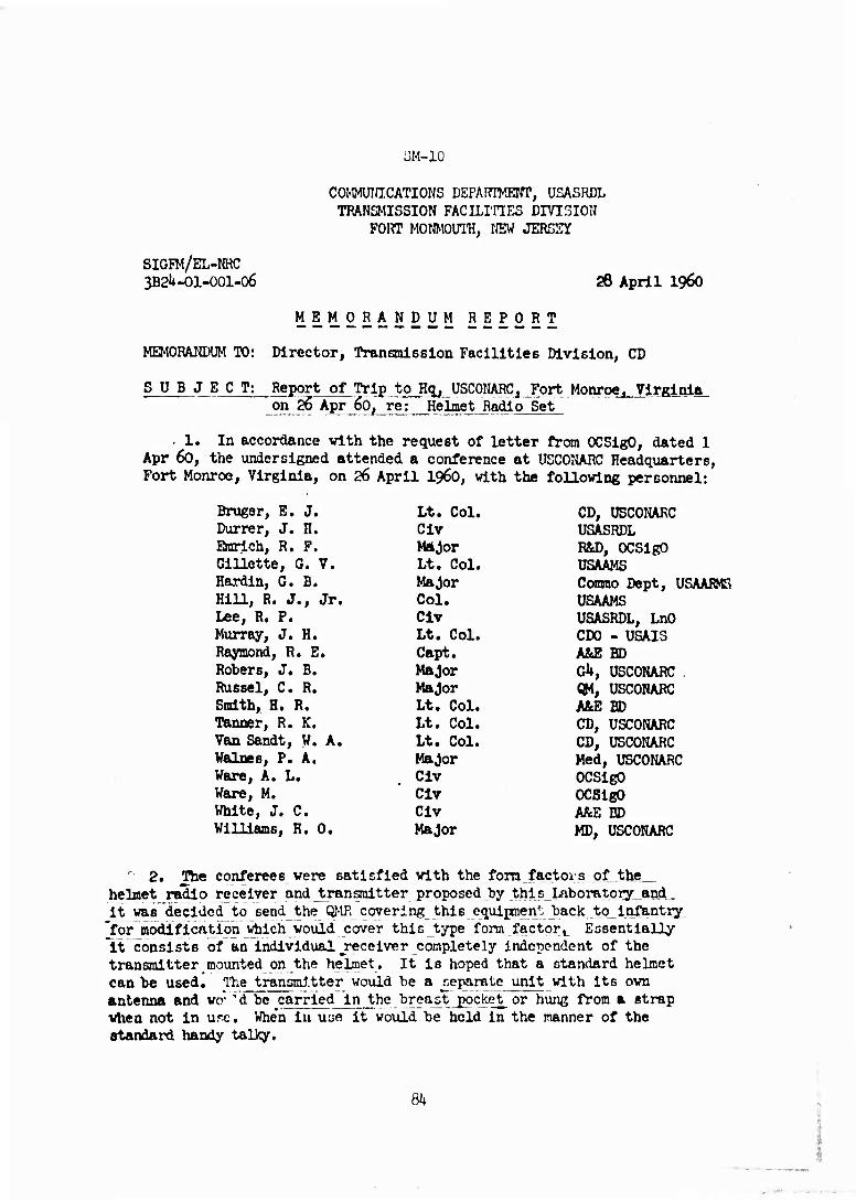
SM-IO
COMMUIUCATIONS DEPAnTKENT, USASRDL TRANSMISSION FACILITIES DIVISION
FORT MONMOUTH, NEW JERSEY
SIGFM/EL-NRC 3B2U-O1-001-06 28 April i960
MEMORANDUM REPORT
MEMORANDUM TO: Director, Trananisslon Facilities Division, CD
SUBJECT: Report of Trip to Hq, USCONARC. Fort Monroe f Virginia on 26 Apr 60, re: Helmet Radio Set
. 1. In accordance with the request of letter from OCSigO, dated 1 Apr 60, the undersigned attended a conference at USCONARC Headquarters, Fort Monroe, Virginia, on 26 April i960, with the following personnel:
CD, USCONARC ÜSASRDL R&D, OCSigO USAAMS Commo Dept, USAARMS USAAMS USASRDL, LnO CDO - USAI3 A&E BD Gh, USCONARC QM, USCONARC A&E BD CD, USCONARC CD, USCONARC Med, USCONARC OCSigO OCSigO A&E BD MD, USCONARC
Bruger, E. J. Lt. Col. Dürrer, J. H. Civ Erarich, R. F. Major Gillette, G. V. Lt. Col. Hardin, G. B. Major Hill, R. J., Jr. Col. Lee, R. P. Civ Murray, J. H. Lt. Col. Raymond, R. E. Capt. Robers, J. B. Major Rüssel, C. R. Major Smith, H. R. Lt. Col. Tanner, R. K. Lt. Col. Van Sandt, W. A. Lt. Col. Walnes, P. A. Major Ware, A. L. Civ Ware, M. Civ White, J, C. Civ Williams, H. 0. Major
' 2. The conferees were satisfied with the form factors of the_ helmet radio receiver and jtransnltter proposed by thls_LfiborRtory„and„ it was decided to send the QMR covering this equipnent back to_infantry
'for modification \rtiich would cover this type form factor, Essentially "it consist8 of an individual ^receiver completely Independent of the transmitter mounted on the helmet. It is hoped that a standard helmet can be used. The transmitter would be a separate unit with its own antenna and wo" 'd be carried in the breastpocket^ or hung from a strap when not In urc. When in u^e it would be held In the manner of the standard handy talky.
8i*

SM-11 HeadquarterB
DEPARTMENT OF THE ARMY Office of the Chief Signal Officer
WaBhlngton 25, D. C.
SIGRD-6-a2
SUBJECT: Squad Radio Set July 27, 19^1
TO: Commanding Officer U. S. Army Signal Research and Development Laboratory !?«>•+ Mr*»im/-«i+Vi MAU .TäVOOV
1. REFERENCES:
S* 2. Considerable efforte have been expended by both your Laboratory and this office in evaluating the many applicable solutions for a relatively inexpensive radio set which will fulfill the requirement of an inexpensive and unsophisticated radio set for squad use. Utlliilng the guidance provided by the U. S. Continental Army Command, the many appli- cable solutions were narrowed to the development of a hand-held trans- mitter and a helmet-mounted receiver similar to those described In references la, lb, 1c, and le above. Because of the emphasis being placed upon low unit costs for these equipments, procurements of these units were proposed on an "equipment performance" basis with a relaxation In component testing and certlf: cation procedures as well as the require- ments for extreme environmental operations and standardization. Pro- curement of 1000 transmitters ani 5000 receivers was proposed based upon the stated utilization factors.
3. By reference lg, your Luhoratory was advised that $1,550,000 had been programmed in FT-1962 Research, Development, Test and Evaluation (RDTSCE) Program for the contractual obligations regarding the development of this radio set. Consequently, it is requested that your Laboratory expedite the following:
a. Preparation of necessary specifications and procurement documents.
b. Establishment of a separate task under Project 3B2U-07-001, "Short Range Radio Coraraunlcatlons," (See Reference Id).
c. Coordination with U. S. Array Signal Materiel Support Agency and the USCONARC's agency to be designated later.
d. Rendering of technical acslBtance to the U. S. Army Airborne and Electronics Board for^tlie_preparatlon of military characteristics.
FOR THE CHIEF SIGNAL OFFICER:
R. F. BRADT Chief, Corranunlcations Branch Research and Development Dlvlcion
8';
^■Jf'^... .^.

SM-12
Miniature Radlos Chief of Staff CD Lt Col Picrce/2Ul6/ab
1. REFERENCES: a. Extract para la, DF, 10 Get 6l, ßubj; "Items of Interest
to General Powell (U)." (TAB A) b. DF, KD to CofS, 12 Get 6l, subj: "Miniature Radio." (TAB B)
2. PROBLEM: To provide for the development of a cdniature radio to communicate between platoon and squad, and between squad leader and selected squad members.
3. DISCUSSION: a. This headquarters was Informed by DA on 19 Oct that the
miniature radio proposed in our present QHR must be a replacement _for jthe AN/PRC-^ radio. The AN/PRC-6 hasa 1 mile range, and is used for communications between platoon and squad leaders. To assure development of an adequate radio, meet infantry requirements for communication between squad leader and squad, and provide a replacement for the AN/PRC- 6, it is necessary to change the existing QMR to provide a two channel, om iaile/500 meter capability.
b. The infantry School (TIS) indicated they would withdraw the request for a troop test of the industry produced, off-the-shelf version of a miniature radio contingent on the QMR change.
c. TIS objects to the time required for normal R&D cycle and requests the development be expedited. The Signal Laboratory engineers
"Save indicated there will be a requirement for R&D effort to produce this new radio.
d. The cost of the receivers will remain the same as estimated for the originally proposed set, i.e., $7!?» The transmitter is expected to cost about $250. Total cost to equip an infantry division, to Include issuing receivers to selected members of the squad (e.g., ftre team leaders) is not expected to exceed $350,000. To Elmilarly equip with the AN/PRC-6 radios would cost approximately $250,000. There are suff- icient AN/PRC-6 radios on hand to fulfill communication requirements pending an orderly development cycle.
h. CONCLUSIONS: a. By developing a suitable replacement for the AN/PRC-6 radio
the requirements of TIS will be met. b. There is not apparent need for an early and accelerated
troop test. ^c. There will be a requirement for some research and develop-
ment effort.
5. RECOMMENDATIONS: a. Change the present QMR to assure the development of a radio
that will suitably replace the AN/rRC-6 and meet TIS stated .requirements. b. Conduct no jtroop test until completion of service test by
Airborne and Electronics Board.
2 Incl (Cont'd) VAN ILVITA
86
....
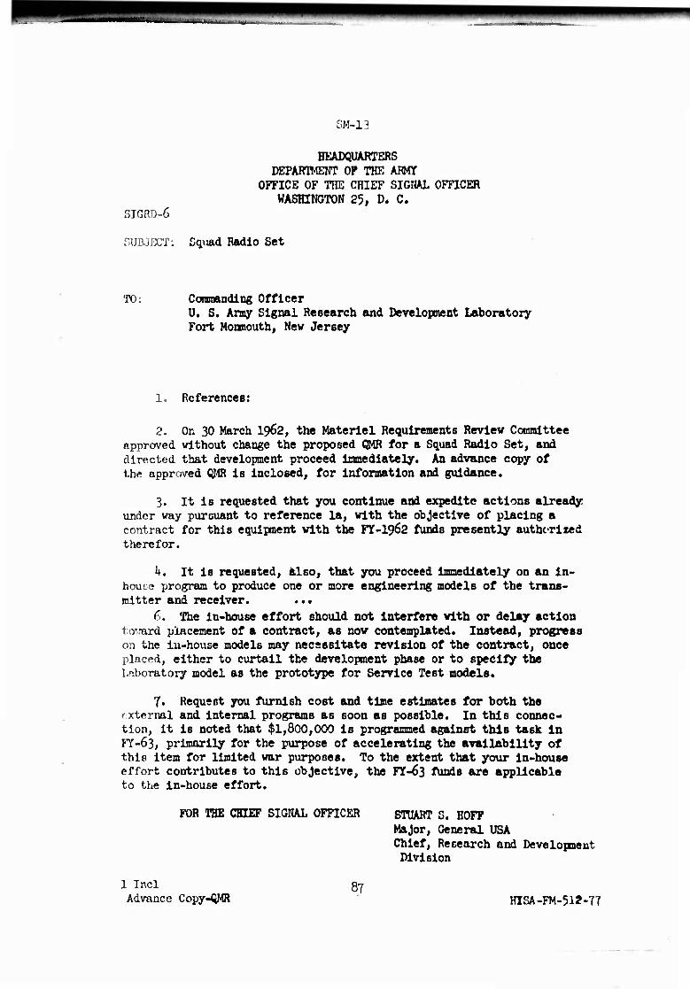
rui'.1.!-,,.! ._
3M-13
SIGRD-6
HEADQUARTERS DEPARTMENT OP THE ARMY
OFFICE OF THE CHIEF SIGNAL OFFICER WASHINGTON 25, D. C.
SUBJECT: Gqmd Radio Set
TO: Commanding Officer U. S. Army Signal Research and Development Laboratory Fort Monmouth, Nev Jersey
1. References:
2. On 30 March 1962, the Materiel Requirements Review Committee approved without change the proposed QMR for a Squad Radio Set, and directed that development proceed immediately. An advance copy of the approved QMR is inclosed, for Information and guidance.
3. It is requested that you continue and expedite actions already under way pursuant to reference la, with the objective of placing a contract for this equlpnent with the FY-I962 funds presently authorized therefor.
k. It is requested, also, that you proceed immediately on an in- tiou- .• program to produce one or more engineering models of the trans- mitter and receiver. ...
6. The in-house effort should not Interfere with or delay action > vam placement of a contract, as now contemplated. Instead, progress on the lu-house models may necessitate revision of the contract, once placed, either to curtail the development phase or to specify the Laboratory model as the prototype for Service Test models.
7. Request you furnish cost and time estimates for both the external and internal programs as soon as possible. In this connec- tion, it is noted that $1,800,000 is programmed against this task in FY-63, primarily for the purpose of accelerating the avallAblllty of this item for limited war purposes. To the extent that your in-house effort contributes to this objective, the F3f-63 funds are applicable to the In-house effort.
FOR THE CHIEF SIGNAL OFFICER HOFF Major, General USA Chief, Research and Development Division
1 Incl Advance Copy-QMR
87 HISA-FM-512-77

5 Z
□
?i in PI I >
o
8
c z
o
s
I ? s i n o o z
a
5 8 C >
o m j - z m z -«
0 ■n
i m > 71
5