ecogun as auto automatic air spray gun - shop.durr.com
TRANSCRIPT

EcoGun AS AUTOAutomatic Air Spray Gun
MSG00019EN, V01
N36210008Vwww.durr.com
Operation manual

Information about the documentThis document describes the correct han-dling of the product.
Read the document prior to every activity.Prepare the document for the application.Pass on the product only together with the complete documentation.Always follow safety instructions, han-dling instructions and specifications of every kind.Illustrations can deviate from the tech-nical construction.
Validity range of the documentThis document describes the following product:
N36210008VEcoGun AS AUTO
Hotline and ContactIf you have queries or would like technical information, please contact your dealer or sales partner.
06/2018EcoGun AS AUTO - MSG00019EN2/40

TABLE OF CONTENTS1 Product overview.......................... 4
1.1 Overview................................ 41.2 Short description.................... 4
2 Safety............................................. 52.1 Presentation of Notes............ 52.2 Intended Use.......................... 52.3 Staff qualification.................... 62.4 Personal protective equip-
ment....................................... 62.5 Residual risks......................... 6
3 Transport, scope of supply and storage........................................... 73.1 Scope of delivery................... 73.2 Handling of
packaging material................. 73.3 Storage.................................. 7
4 Assembly....................................... 84.1 Requirements for the
Installation point..................... 84.2 Assembly............................... 84.3 Setting the spray jet............... 9
5 Commissioning........................... 10
6 Operation..................................... 126.1 Safety recommendations..... 126.2 Checks................................. 126.3 Selecting air cap.................. 126.4 Rinsing................................. 136.4.1 Safety recommendations.. 136.4.2 General notes................... 136.4.3 Rinsing.............................. 13
7 Cleaning and maintenance........ 137.1 Safety recommendations..... 137.2 Cleaning............................... 157.3 Maintenance........................ 167.3.1 Maintenance schedule...... 167.3.2 Lubrication........................ 16
8 Faults........................................... 168.1 Safety recommendations .... 168.2 Defects table........................ 178.3 Troubleshooting................... 208.3.1 Replace needle and
nozzle................................ 208.3.2 Replace needle seal......... 218.3.3 Replace piston and piston
seals.................................. 22
9 Disassembly and Disposal........ 239.1 Safety recommendations..... 239.2 Disassembly......................... 239.3 Disposal .............................. 24
10 Technical data............................. 2410.1 Dimensions and weight...... 2410.2 Connections....................... 2410.3 Operating conditions.......... 2410.4 Emissions........................... 2410.5 Operating values................ 2510.6 Type plate.......................... 2510.7 Materials used.................... 2510.8 Operating and auxiliary
materials............................ 2510.9 Material specification......... 25
11 Replacement parts, tools and accessories................................. 2611.1 Replacement parts............. 2611.2 Tools................................... 3111.3 Accessories........................ 3211.4 Order.................................. 38
06/2018 EcoGun AS AUTO - MSG00019EN 3/40
1 Product overview1.1 Overview
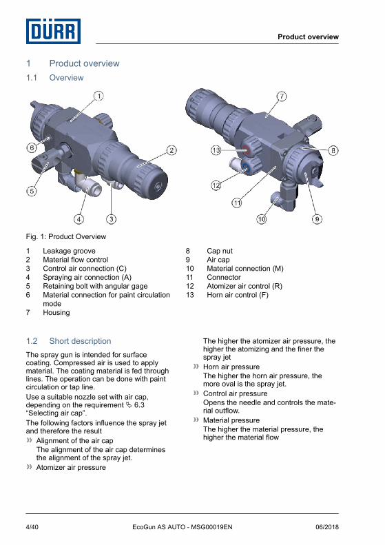
Fig. 1: Product Overview
1 Leakage groove2 Material flow control3 Control air connection (C)4 Spraying air connection (A)5 Retaining bolt with angular gage6 Material connection for paint circulation
mode7 Housing
8 Cap nut9 Air cap10 Material connection (M)11 Connector12 Atomizer air control (R)13 Horn air control (F)
1.2 Short descriptionThe spray gun is intended for surface coating. Compressed air is used to apply material. The coating material is fed through lines. The operation can be done with paint circulation or tap line.Use a suitable nozzle set with air cap, depending on the requirement Ä 6.3 “Selecting air cap”.The following factors influence the spray jet and therefore the result
Alignment of the air capThe alignment of the air cap determines the alignment of the spray jet.Atomizer air pressure
The higher the atomizer air pressure, the higher the atomizing and the finer the spray jetHorn air pressureThe higher the horn air pressure, the more oval is the spray jet.Control air pressureOpens the needle and controls the mate-rial outflow.Material pressureThe higher the material pressure, the higher the material flow
Product overview
06/2018EcoGun AS AUTO - MSG00019EN4/40

Control air pressure is controlled externally via valves. The horn air pressure and spraying air pressure can be adjusted on the spray gun by means of the horn air pressure (F) and the atomizer air control (R). The spraying air pressure (A) is controlled exter-nally via valves. You can also regulate the material flow via the material flow control, if it is not controlled externally.
2 Safety2.1 Presentation of NotesThe following notes can appear in this instructions manual.
DANGER!
High risk situation that can lead to serious injuries or death.
WARNING!
Medium risk situation that can lead to serious injuries or death.
CAUTION!
Low risk situations that can lead to minor injuries.
NOTICE!
Situations that can lead to material damage.
ENVIRONMENT!
Situations that can lead to environmental damage.
Contains additional information and recommendations.
2.2 Intended UseUseThe EcoGun AS AUTO spray gun is solely intended for automatic coating of surfaces by one of the following operating methods:
as independent, not hand guided, deviceas part of a semi- or fully automated paint boothas part of a paint robot
The material feed can be effected optionally via the pressure line or under gravitation (flow beaker).The product is only intended for industrial use within the specified technical data. Ä 10 “Technical data”The spray gun is approved for use in explo-sive areas of Ex zones 1 and 2.
MisuseIf used incorrectly, it can cause serious inju-ries or death.Misuses include, e. g.:
Aiming the spray gun at humans or ani-mals.Atomization of fluid nitrogenUse of unapproved materialsCombination of the spray gun with com-ponents that are not approved by Dürr Systems for operation.Making conversions or changes on your ownUse in explosive areas Ex zone 0
EX labeling
II 2G T6 X
II - Device group II: all areas except mining
2G - Device category 2 for gas
T6 - Temperature class T6: Surface tem-perature, max. 85 °C
X - Specific conditions for safe operation
Safety
06/2018 EcoGun AS AUTO - MSG00019EN 5/40

The following conditions must be observed for safe operation:
Ground spray gun and work piece.Only use conductive lines.Ensure that static electricity can be dis-charged.
2.3 Staff qualification
WARNING!
Inadequate qualificationWrong estimation of dangers can cause serious injury or death.– Only sufficiently qualified persons may
execute all work.– Some work requires additional qualifi-
cation. Additional qualifications are marked with a “+”.
This document is intended for qualified per-sonnel in the industry.OperatorThe operator is trained specifically for the field of work in which he works.Furthermore, the operator possesses the fol-lowing knowledge:
Technical Measures for occupational safety and health
The operator is responsible for the following work:
Operate and monitor the system/ product.Introduce measures in the event of faults.Clean system/ product.
+ additional qualification explosion pro-tectionIn addition to the knowledge of the various specialist fields, the mechanic has knowl-edge of regulations and safety measures when working in potentially explosive areas.
Dürr Systems offers special product training for Ä “Hotline and Contact”.
2.4 Personal protective equipmentWear the required personal protective equip-ment when working. Provide the following personal protective equipment:
2.5 Residual risksExplosionSparks, open flames and hot surfaces can cause explosions in explosive atmospheres. Serious injuries and death can be the conse-quence.
Before carrying out any work, ensure a non-explosive atmosphere.Do not use sources of ignition and open light.Do not smoke.Ground the product.Ground the work piece.Only use conductive lines.
Flammable coating materials and their deter-gents and cleaning agents can cause a fire or an explosion.
Ensure that the flashpoint of the fluid is at least 15 K above the ambient tempera-ture.Note explosion group of the fluid.Follow safety data sheets.Ensure that forced ventilation and fire protection equipment are in operation.Do not use any sources of ignition and open light.Do not smoke.
Danger from harmful or irritant sub-stancesContact with hazardous liquids or vapors, can result in serious injury or death.
Safety
06/2018EcoGun AS AUTO - MSG00019EN6/40

Ensure that the forced ventilation is operational.Follow safety data sheets.Wear specified protective equipment.
Escaping materialMaterial escaping under pressure can cause serious injuries.Before working on the product:
Disconnect the system with the product from compressed air and material supply.Relieve the lines.Secure the system against reconnection.
Movable componentsThere is a risk of death if components or equipment in the vicinity move unexpectedly.
Switch off and lock out all system compo-nents against being switched on again before working on the product.
NoiseThe noise during normal operation may cause severe hearing damage.
Wear hearing protection.Do not spend more time then necessary in the work area.
Hot surfacesDuring normal operation the surfaces of components can get extremely hot. Contact with it can cause burns.Before carrying out any work:
Check the temperature.Do not touch hot surfaces.Let components cool down.Wear protective gloves.
3 Transport, scope of supply and storage
3.1 Scope of deliveryThe scope of supply includes the following components:
Spray gunTool kit Ä 11.1 “Replacement parts”
Inspect delivery on receipt for completeness and integrity.Report defects immediately Ä “Hotline and Contact”.
3.2 Handling of packaging material
ENVIRONMENT!
Incorrect disposalIncorrectly disposed packaging material can damage environment.– Dispose of material no longer required
in an environment-friendly manner.– Observe local disposal specifications.
3.3 StorageRequirements for the warehouse:
Do not store outdoors.Store in a dry and dust-free place.Do not expose to aggressive media.Protect from solar radiation.Avoid mechanical vibrations.Temperature: 10 °C to 40°CRelative humidity: 35% to 90%
Transport, scope of supply and storage
06/2018 EcoGun AS AUTO - MSG00019EN 7/40

4 Assembly4.1 Requirements for the
Installation point.It must be possible to disconnect the compressed air supply and material feed to the spray gun and secure it against reconnection.Lines, seals and screw connections must be designed to conform to the spray gun requirements Ä 10.5 “Operating values”.A fastening device capable of securing the spray gun is required.The control air supply must be adjustable.
4.2 AssemblyStationary assemblyPersonnel:
Operator + additional qualification explosion pro-tection
Protective equipment:Protective workwearProtective gloves
Observe the following at assembly:Bore of the retaining bolt: 10 mmNominal diameters: Ä 10.2 “Connections”
1. WARNING!
Sources of ignition may cause explo-sions!
Ensure a non-explosive atmosphere.
Fig. 2: Assembly
2. Loosen screw (1) using a hexagon socket screwdriver.
3. Slide the spray gun with the bore of the fastening bolt (4) onto the support bracket.
4. Tighten screw (1) using a hexagon socket screwdriver.
5. Loosen locknut (3).
6. Set orientation angle by using angular gage (2).
Alignment is not important. Dis-tance to the work piece: 15 to 25 cm.
7. Tighten the locknut (3).
Assembly
06/2018EcoGun AS AUTO - MSG00019EN8/40

8. WARNING!
Statically charges components may cause explosions during operation!
Ground the spray gun through the fas-tening bore or material connection lines, if the fastening device itself is non-conduc-tive or is not grounded. Ensure housing contract.
Resistance between housing and grounding terminal ≤ 1 MΩ.
Fig. 3: Connect
9. The spray gun does not work when the lines are not connected correctly.
Connect lines. Ensure correct assign-ment.1 - Material (M)
2 - Spraying air (A)
3 - Control air (C)
Connect lines to both material connections (M) for paint circula-tion mode.For tap line mode, connect line to a material connection. Lock the other material connection by means of the sealing screw.
4.3 Setting the spray jetPersonnel:
Operator + additional qualification explosion pro-tection
Protective equipment:Protective workwearProtective gloves
Fig. 4: Setting the spray jet
Assembly
06/2018 EcoGun AS AUTO - MSG00019EN 9/40

You can rotate the air cap (2) to any position to change the alignment of the spray jet.
1. Loosen the cap nut (1).
Fig. 5: Air cap alignment
2. Rotate air cap (2) in the required position.
3. Hand tighten the cap nut (1).
5 CommissioningPersonnel:
Operator + additional qualification explosion pro-tection
Protective equipment:Use ear protectionEye protectionRespiratory protection deviceProtective workwearProtective gloves
Depending on the design of the application system, two technicians must be present to execute the commissioning.
Technician 1: Operates the controlsTechnician 2: Check on the spray gun.
1. Actuate the spray gun without material via the control unit or the visualizer.
2. Check the switching behavior.Does the needle open and close as required?Are all types of air supply connected?
3. Rinse spray gun. Ä 6.4 “Rinsing”
4. Connect material.
5. Create a trial spray pattern on a test work piece.
Setting the spray patternPersonnel:
Operator + additional qualification explosion pro-tection
Protective equipment:Use ear protectionEye protectionRespiratory protection deviceProtective workwearProtective gloves
You can adjust the spray pattern continu-ously between round and flat.
Commissioning
06/2018EcoGun AS AUTO - MSG00019EN10/40

You can vary the size of the spray pattern by adjusting the distance between the spray gun and the work piece.
Fig. 6: Setting the spray pattern
1. Set material flow via valves in control cabinet or at material flow control (1).
Open the material flow control on the spray gun when controlling via the regulation cabinet.
2. Set atomizer air using valves in the con-trol cabinet or on the atomizer air control (R) (3).
Observe the following character-istic curve.
3. Set horn air using valves in the control cabinet or on the horn air control (F) (2).ðWhen the horn air is blocked, the
spray pattern is round.
Characteristic curve
Fig. 7: Characteristic curve
1 Flat spray pattern2 Round spray patternX axis Atomizer air pressure [bar (psi)]Y axis Flow rate [Nl/min (CFM)]
The characteristic curves show the relation between atomizer air pressure and air con-sumption when using the air caps PL and HM with a diameter of 1.0 mm as well as the air cap PC with the diameter 1.6 mm.To achieve the highest possible transfer rate, the air pressure should be kept as low as possible Ä 6.3 “Selecting air cap”, Ä 10.5 “Operating values”.
Commissioning
06/2018 EcoGun AS AUTO - MSG00019EN 11/40

6 Operation6.1 Safety recommendations
WARNING!
Danger of explosion due to chemical reactionsMaterial, halogenated hydrocarbon-based rinsing agent or cleaning agent can chemi-cally react with aluminum components of the product. Chemical reactions can cause explosions. Serious injuries and death can be the consequence.– Only use rinsing agents and cleaning
agents that do not contain any halo-genated hydrocarbons.
NOTICE!
Material damage due to dried material residuesIf material residues dry in the product, that can harm components.– Rinse product immediately after each
use.
6.2 Checks1. Perform the following checks during oper-
ation:Check air connection for correct seat and leaks.Check air car for cleanliness.Check nozzle for cleanliness.
6.3 Selecting air capYou can convert the spray gun for various uses by swapping the air cap.
Air cap PLThe air cap PL is used for:
TopcoatsAutomotive paintsClear coatsMordant
The air cap PL is used for the application of paints with a viscosity up to about 25 s/Ford Becher 4.
Air cap PCThe air cap PC is used for flammable and non-flammable fluid coating materials (1-component paints and 2-component paints). It is used for application of fillers, base coats and topcoats.
Air cap HM (HVLP)The low mist air cap (HVLP) HM is used for:
Finish coatTopcoatsAutomotive paintsTransparent paintsMordant
It is used for the application of paints with a viscosity up to about 20 s/Ford Becher 4.The air pressure at the gun inlet must not exceed 1.8 bar (26 psi) to achieve the max-imum material transfer rate (called HVLP method). 1.8 bar (26 psi) at the gun inlet cor-respond to 0.7 bar (10 psi) below the air cap. HVLP Test-Set Ä 11.3 “Accessories”
Operation
06/2018EcoGun AS AUTO - MSG00019EN12/40

6.4 Rinsing6.4.1 Safety recommendations
NOTICE!
Material damage due to unsuitable rinsing agentIf the rinsing agent reacts chemically with the components or the material, compo-nents get damaged.– Use only the rinsing agents that are
compatible with the components and the material.
– Refer to safety data sheet of material manufacturer.
6.4.2 General notesWhen rinsing, use fluid to remove inner soiling from components.
6.4.3 RinsingPersonnel:
Operator + additional qualification explosion pro-tection
Protective equipment:Use ear protectionEye protectionRespiratory protection deviceProtective workwearProtective gloves
The spray gun must be rinsed:After end of workBefore every change of materialPrior to cleaningPrior to dismantlingBefore a long time of non-useBefore placing in storage
Additional rinsing intervals depend on the material used.
1. Rinse the spray gun with an appropriate rinsing agent until the rinsing agent runs clean without any material residue.
7 Cleaning and maintenance7.1 Safety recommendations
WARNING!
Danger of fire and explosionFlammable coating materials and their detergents and cleaning agents can cause a fire or an explosion.– Ensure that the flashpoint of the fluid is
at least 15 K above the ambient tem-perature.
– Note explosion group of the fluid.– Follow safety data sheets.– Ensure that forced ventilation and fire
protection equipment are in operation.– Do not use sources of ignition and
open light.– Do not smoke.
WARNING!
Risk of injury from unsuitable replace-ment parts in explosive areas.Replacement parts not compliant with the specifications of the ATEX guidelines can cause explosions in an explosive atmos-phere. Serious injuries and death can be the consequence.– Use exclusively original replacement
parts.
Cleaning and maintenance
06/2018 EcoGun AS AUTO - MSG00019EN 13/40

WARNING!
Danger to health from harmful or irri-tant substancesContact with hazardous liquids or vapors, can result in serious injury or death.– Ensure that the forced ventilation is
operational.– Follow safety data sheets.– Wear specified protective clothing.
WARNING!
Risk of injury due to escaping material and compressed airEscaping compressed material can cause serious injury.Before carrying out any work:– Disconnect the system, in which the
spray gun is installed, from com-pressed air and material supply.
– Secure the system against reconnec-tion.
– Relieve the lines.
WARNING!
Danger of explosion due to chemical reactionsMaterial, halogenated hydrocarbon-based rinsing agent or cleaning agent can chemi-cally react with aluminum components of the product. Chemical reactions can cause explosions. Serious injuries and death can be the consequence.– Only use rinsing agents and cleaning
agents that do not contain any halo-genated hydrocarbons.
NOTICE!
Unsuitable cleaning agentsUnsuitable cleaning agents can damage the product.– Only use cleaning agents approved by
the material manufacturer.– Follow safety data sheets.– Place heavily soiled components in a
cleaning bath.– Only place those parts in the
cleaning bath, which are suitable for the cleaning bath.
– Use only electrically conductive containers.
– Ground the container.– Do not use ultrasound baths.
Use alcohols (isopropanol, butanol) for non-flammable coating materials.Remove dried non-flammable coating materials using a material manufacturer- approved organic thinner.
NOTICE!
Damage due to unsuitable cleaning toolsUnsuitable cleaning tools can damage the product.– Only use cloths, soft brushes and
paintbrushes.– Do not use abrasive cleaning tools.– Do not poke blocked nozzles with met-
allic objects.– Do not use compressed air for
cleaning.– Do not use any thinner spray guns.– Do not use high pressure for cleaning
agents.
Cleaning and maintenance
06/2018EcoGun AS AUTO - MSG00019EN14/40
7.2 CleaningClean the spray gun.Personnel:
Operator + additional qualification explosion pro-tection
Protective equipment:Use ear protectionEye protectionRespiratory protection deviceProtective workwearProtective gloves
1. Rinse spray gun. Ä 6.4 “Rinsing”
2. Use a cleaning agent to carefully clean the spray gun. Dry with a soft cloth.
Cleaning the air cap und nozzleFor a thorough cleaning you can remove the air cap and the nozzle.
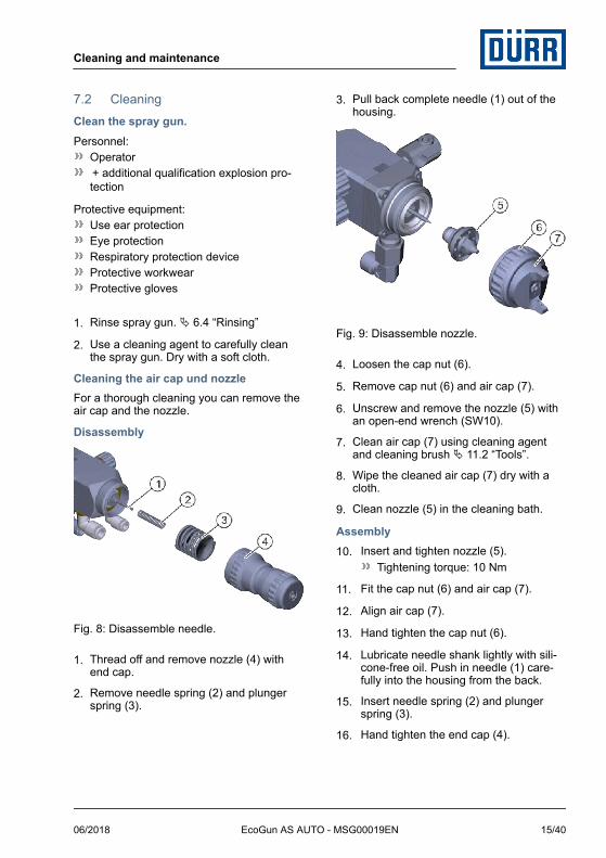
Disassembly
Fig. 8: Disassemble needle.
1. Thread off and remove nozzle (4) with end cap.
2. Remove needle spring (2) and plunger spring (3).
3. Pull back complete needle (1) out of the housing.
Fig. 9: Disassemble nozzle.
4. Loosen the cap nut (6).
5. Remove cap nut (6) and air cap (7).
6. Unscrew and remove the nozzle (5) with an open-end wrench (SW10).
7. Clean air cap (7) using cleaning agent and cleaning brush Ä 11.2 “Tools”.
8. Wipe the cleaned air cap (7) dry with a cloth.
9. Clean nozzle (5) in the cleaning bath.
Assembly10. Insert and tighten nozzle (5).
Tightening torque: 10 Nm
11. Fit the cap nut (6) and air cap (7).
12. Align air cap (7).
13. Hand tighten the cap nut (6).
14. Lubricate needle shank lightly with sili-cone-free oil. Push in needle (1) care-fully into the housing from the back.
15. Insert needle spring (2) and plunger spring (3).
16. Hand tighten the end cap (4).
Cleaning and maintenance
06/2018 EcoGun AS AUTO - MSG00019EN 15/40

7.3 Maintenance7.3.1 Maintenance scheduleThe maintenance intervals given below are based on experiential values. Maintenance intervals, adjust individually if necessary.
Interval Maintenance work
Daily Check condition and tightness (also of the connections and lines).Check fastening
Before every change of material Cleaning Ä 7.2 “Cleaning”.
Monthly Lubricate internal components Ä 7.3.2 “Lubrication”.
After each alteration Check grounding Ä 4.2 “Assembly”.
7.3.2 LubricationPersonnel:
Operator + additional qualification explosion pro-tection
Protective equipment:Protective workwearProtective gloves
Needle shank, piston, piston sliding surfaces and gasket must be lubricated so that there will not be any leakages.
Fig. 10: Lubricating piston components
1. Feed a drop of lubricant (silicone-free oil) at the control air connection (C) (1) using the control air.
8 Faults8.1 Safety recommendations
CAUTION!
Risk of injury due to spring tensionThe end cap of the spray gun is under spring tension. If you remove the end cap, the spring tension could cause the end cap to jump out unexpectedly and cause light injuries.– Removing and installing end cap
Faults
06/2018EcoGun AS AUTO - MSG00019EN16/40

NOTICE!
Property damage due to improper replacement of needle and nozzleReplacing only the needle or only the nozzle could damage spray gun compo-nents. This can compromise the tightness of the spray gun. The spray pattern deteri-orates.– Observe order of replacement steps
(needle – nozzle).– Observe order of assembly steps
(nozzle – needle).– Always replace nozzle and needle at
the same time.
NOTICE!
Property damage due to improper han-dlingMechanical load can damage needle and nozzle.– Handle with care during installation
and dismantling.– Do not subject the needle to any
mechanical pressure.– Avoid collisions of components to be
assembled and disassembled with the needle.
– Do not excessively tighten compo-nents.
8.2 Defects tableVisualizer of typical spray pattern problems
Spray pattern Fault identification
Spray jet is distorted.
Spray jet is bent or tapered.
Spray jet is too thick in the middle.
Spray jet is split.
Faults
06/2018 EcoGun AS AUTO - MSG00019EN 17/40

Spray pattern Fault identification
Spray jet is uneven.
Spray jet is sickle-shaped.
Fault description Cause Remedy
No material Line pinched or broken Check the line.
Needle does not open. Check control air.
Material leaking when needle is closed.
Needle does not close correctly.
Check control air venting.Check operation of needle. Replace needle, if defective, together with the nozzle Ä 8.3.1 “Replace needle and nozzle.”.
Nozzle soiled or defec-tive.
Clean and check the nozzle. If nozzle is defective, replace it along with the needle Ä 8.3.1 “Replace needle and nozzle.”.
Air leaks from the material flow control
Piston worn out Replace piston Ä 8.3.3 “Replace piston and piston seals.”.
Air leak from the leakage slot
Gasket worn out Have it replaced by Dürr Systems.
Material leaks from the leakage-slot
Needle gland worn out Replace needle gland Ä 8.3.2 “Replace needle seal”.
Spray jet misaligned Air cap is misaligned. Rotate air cap into the required position Ä 4.3 “Setting the spray jet”.
Spray jet too strong in center.
Too much material Reduce material feed.Increase spraying air pressure (A).
Material too viscous. Change material consistency.
Horn air pressure too low
Raise horn air pressure using the horn air control (F).
Split spray jet Not enough material. Increase material feed.
Faults
06/2018EcoGun AS AUTO - MSG00019EN18/40

Fault description Cause RemedyReduce spraying air pressure (A).
Material too thin. Change material consistency.
Horn air pressure too high
Raise horn air pressure using the horn air control (F).
Cone-shaped spray jet
Bores in air cap are soiled.
Clean and check air cap Ä 7.2 “Cleaning”. Replace air cap if defective Ä 8.3.1 “Replace needle and nozzle.”.
Nozzle soiled or defec-tive.
Clean and check the nozzle Ä 7.2 “Cleaning”. If nozzle is defective, replace it along with the needle Ä 8.3.1 “Replace needle and nozzle.”.
Sickle-shaped spray jet
Bores in air cap are soiled.
Clean and check air cap Ä 7.2 “Cleaning”. Replace air cap if defective Ä 8.3.1 “Replace needle and nozzle.”.
Nozzle soiled or defec-tive.
Clean and check the nozzle Ä 7.2 “Cleaning”. If nozzle is defective, replace it along with the needle Ä 8.3.1 “Replace needle and nozzle.”.
Cap nut or nozzle is not properly tightened.
Tighten cap nut and nozzle.
Uneven spray jet Nozzle soiled or defec-tive.
Clean and check the nozzle Ä 7.2 “Cleaning”. If nozzle is defective, replace it along with the needle Ä 8.3.1 “Replace needle and nozzle.”.
Material pressure too low.
Increase material pressure.
Feed line pinched or broken.
Check the feed line.
Needle does not close correctly.
Check control air.Check operation of needle. Replace needle, if defective, together with the nozzle Ä 8.3.1 “Replace needle and nozzle.”.
Cap nut or nozzle is not properly tightened.
Tighten cap nut and nozzle.
Faults
06/2018 EcoGun AS AUTO - MSG00019EN 19/40

Fault description Cause Remedy
Needle seal worn out. Replace needle seal Ä 8.3.2 “Replace needle seal”.
8.3 Troubleshooting8.3.1 Replace needle and nozzle.Personnel:
Operator + additional qualification explosion pro-tection
Protective equipment:Protective workwearProtective gloves
Fig. 11: Disassembling Needle
Disassembly1. Thread off and remove nozzle (4) with
end cap.
2. Remove needle spring (2) and plunger spring (3).
3. Pull back complete needle (1) out of the housing.
Fig. 12: Disassemble nozzle.
4. Loosen the cap nut (6).
5. Remove cap nut (6) and air cap (7).
6. Unscrew and remove the nozzle (5) with an open-end wrench (SW10).
7. Replace worn out or defective compo-nents.
Assembling8. Insert and tighten nozzle (5).
Tightening torque: 10 Nm
Depending on the use case, use a nozzle with a suitable diameter.
9. Fit the cap nut (6) and air cap (7).
10. Align air cap (7).
11. Hand tighten the cap nut (6).
Faults
06/2018EcoGun AS AUTO - MSG00019EN20/40
12. Lubricate needle shank lightly with sili-cone-free oil. Push in needle (1) care-fully into the housing from the back.
13. Insert needle spring (2) and plunger spring (3).
14. Hand tighten the end cap (4).
8.3.2 Replace needle sealPersonnel:
Operator + additional qualification explosion pro-tection
Protective equipment:Protective workwearProtective gloves
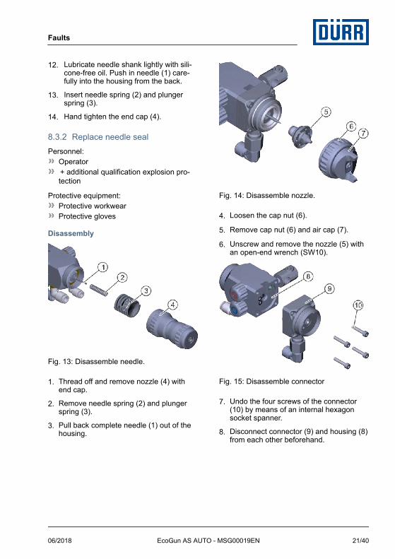
Disassembly
Fig. 13: Disassemble needle.
1. Thread off and remove nozzle (4) with end cap.
2. Remove needle spring (2) and plunger spring (3).
3. Pull back complete needle (1) out of the housing.
Fig. 14: Disassemble nozzle.
4. Loosen the cap nut (6).
5. Remove cap nut (6) and air cap (7).
6. Unscrew and remove the nozzle (5) with an open-end wrench (SW10).
Fig. 15: Disassemble connector
7. Undo the four screws of the connector (10) by means of an internal hexagon socket spanner.
8. Disconnect connector (9) and housing (8) from each other beforehand.
Faults
06/2018 EcoGun AS AUTO - MSG00019EN 21/40

Fig. 16: Remove needle gland
9. Push out needle gland (11) towards the front from the connector (9). Possibly. Use installation wrench.
10. Replace worn out or defective compo-nents.
Assembly11. Insert needle gland (11) in the con-
nector (9). Possibly. Use installation wrench. Observe installation position.
12. Connect connector (9) and housing (8) to each other.
13. Insert the four screws of the connecting piece (9). Tighten using a hexagon socket screwdriver.
14. Insert and tighten nozzle (5).Tightening torque: 10 Nm
15. Fit the cap nut (6) and air cap (7).
16. Align air cap (7).
17. Hand tighten the cap nut (6).
18. Lubricate needle shank lightly with sili-cone-free oil. Push in needle (1) care-fully into the housing from the back.
19. Insert needle spring (2) and plunger spring (3).
20. Hand tighten the end cap (4).
8.3.3 Replace piston and piston seals.Personnel:
Operator + additional qualification explosion pro-tection
Protective equipment:Protective workwearProtective gloves
Disassembly
Fig. 17: Disassemble needle.
1. Thread off and remove nozzle (4) with end cap.
2. Remove needle spring (2) and plunger spring (3).
3. Pull back complete needle (1) out of the housing.
Faults
06/2018EcoGun AS AUTO - MSG00019EN22/40

Fig. 18: Disassemble piston.
4. Pull out piston bearing (7) and piston (6) with O-ring (5).
5. Replace worn out or defective compo-nents.
Assembly6. Insert piston (6) with pre-assembled O-
ring (5) and piston bearing (7).
7. Lubricate needle shank lightly with sili-cone-free oil. Push in needle (1) carefully into the housing from the back.
8. Insert needle spring (2) and plunger spring (3).
9. Hand tighten the end cap (4).
9 Disassembly and Disposal9.1 Safety recommendations
WARNING!
Risk of injury due to escaping material and compressed airEscaping compressed material can cause serious injury.Before carrying out any work:– Disconnect the system, in which the
spray gun is installed, from com-pressed air and material supply.
– Secure the system against reconnec-tion.
– Relieve the lines.
9.2 DisassemblyPersonnel:
Operator + additional qualification explosion pro-tection
Protective equipment:Use ear protectionEye protectionRespiratory protection deviceProtective workwearProtective gloves
1. Rinsing Ä 6.4 “Rinsing”.
2. Disconnect the compressed air supply and material feed. Secure against recon-nection.
3. Disconnect all lines.
4. Disassemble the spray gun from the sup-port bracket.
Disassembly and Disposal
06/2018 EcoGun AS AUTO - MSG00019EN 23/40

9.3 Disposal
ENVIRONMENT!
Incorrect disposalImproper waste disposal threatens the environment and prevents re-use and recycling.– Always dispose of components in
accordance with their characteristic.Ä 10.7 “Materials used”
– Collect leaked out operating and auxil-iary materials completely.
– Dispose of operating and auxiliary materials according to the disposal provisions in force.
– In case of doubt, refer to the local dis-posal authorities.
10 Technical data10.1 Dimensions and weight
Fig. 19: Dimensions
Detail Value
Length with tool-adjustable material flow control
157.5 mm
Length with micro-regulation B (manual adjustment)
167 mm
Detail Value
Length with micro-regulation S (manual adjustment, fine)
182 mm
Width (without sup-port bracket)
56 mm
Height 82.5 mm
Weight 725 g
Nozzle diameter 0.8 to 2.2 mm
10.2 Connections
Connection Nominal width
Material M 14 x 1.5 (Ø 8/6 mm)
Control air Ø 6/4 mm Push-in
Spraying air Ø 8/6 mm Push-in
10.3 Operating conditions
Detail Value
Min. ambient temperature 2 °C
Max. ambient temperature 55 °C
10.4 Emissions
Detail Value
Emission sound pressure level LpA, A – according to EN 14462
88.5 dB
Uncertainty KpA 5 dB
Sound power level LWA, A – according to EN14462
102.4 dB
Uncertainty KWA 5 dB
Technical data
06/2018EcoGun AS AUTO - MSG00019EN24/40

10.5 Operating values
Detail Value
Spraying air pressure, maximum
6 bar (87 psi)
Control air pressure, optimum.
4 bar (58 psi)
Material pressure, max-imum
6 bar (87 psi)
Air pressure HM air cap (HVLP), maximum
1.8 bar (26 psi)
10.6 Type plateProduct designationMaterial numberYear of manufactureSerial numberEX labellingManufacturerCE labelling
10.7 Materials used
Component Material
Housing Stainless steel, alu-minum
Component Material
Compression springs
Stainless steel
Materials in contact with material
Stainless steel
Seals in contact with material
PTFE, PA
Seals without mate-rial contact
NBR
10.8 Operating and auxiliary materials
Denomination Material number
Grease Klüber Syn-theso GLEP 1, 100 g (for seals and threads)
W32020010
10.9 Material specificationSuitable Material:
Water-based or solvent based coating materials
Do not use halogen - hydrocarbon based material.
Technical data
06/2018 EcoGun AS AUTO - MSG00019EN 25/40

11 Replacement parts, tools and accessories11.1 Replacement parts
Fig. 20: Exploded view
Klüber Syntheso GLEP1
Item Description Quan-tity
Material no.
1 Air cap 1 Ä “Overview - Air caps and nozzles”
2 O-ring 33 x 1.6 1
3 Nozzle 1 Ä “Overview - Air caps and nozzles”
Replacement parts, tools and accessories
06/2018EcoGun AS AUTO - MSG00019EN26/40

Item Description Quan-tity
Material no.
4 Needle 1 Ä “Overview - Air caps and nozzles”
5 O-ring 10x1 1
6 Screw M 4 x 20 4
7 Needle gland 1
8 Connector 1
9 O-ring 4x1 2
10 O-ring 5x1 1
11 Seal 1
12 Connection nozzle M 14 x 1.5 1
13 Elbow M 14 x 1.5 8L SST 1
14 Seal 1
15 Locking screw G1/8" 1
16 Elbow plug-in connection D8 1/8” 1 M57310092
17 Elbow plug-in connection D6 1/8” 1 M57310083
18 Housing 1
19 Washer 1 N66030004
20 Positioning disc 1
21 Locknut 1
22 Screw 1
23 Retaining bolt 1
24 Gasket 1
25 O-Ring 11 x 1.8 1
26 Piston 1
27 Piston bearing 1
28 Plunger spring 1
29 Needle spring 1
Replacement parts, tools and accessories
06/2018 EcoGun AS AUTO - MSG00019EN 27/40

Item Description Quan-tity
Material no.
30 Material flow control B (manual adjustment, fine) 1 N36960072
31 Material flow control S (manual adjustment) 1 N36960073
32 Tool-adjustable material flow control 1 N36960074
33 Countersunk-head screw M 3.5 x 8 2
34 Color ring (red) 1
35 Rotary control 2
36 Control bush 2
37 Seal 2
38 Control screw 2
39 Color ring (blue) 1
Overview - Air caps and nozzles
Nozzle sets consist of needle and nozzle with or without air cap.For optional HVLP test set see Ä 11.3 “Accessories”
Nozzle sets with air cap
Nozzle diameter Item no. Nozzle set PL Nozzle set PC Nozzle set HM (HVLP)
0.8 mm 1, 3, 4 M09800139 - -
1.0 mm M09800140 M09800187
1.2 mm M09800141 M09800188
1.6 mm - M09800183 -
1.8 mm M09800184
Replacement parts, tools and accessories
06/2018EcoGun AS AUTO - MSG00019EN28/40

Nozzle diameter Item no. Nozzle set PL Nozzle set PC Nozzle set HM (HVLP)
2.0 mm M09800185
2.2 mm M09800186
Nozzle sets without air cap
Nozzle diameter Item no. Nozzle set PL Nozzle set PC Nozzle set HM (HVLP)
0.8 mm 3, 4 M09800069 - -
1.0 mm M09800070 M09800072
1.2 mm M09800071 M09800073
1.6 mm - M09800074 -
1.8 mm M09800075
2.0 mm M09800076
2.2 mm M09800077
Air caps
Nozzle diameter Item no. Material no.
Air cap PL 0.8 to 1.2 mm 1 M35030087
Air cap PC 1.6 to 2.2mm M35030091
Air cap HM (HVLP) 1.0 to 1.2 mm M35030092
Seal set N36960040
Denomination Item no. Quantity
O-ring 33 x 1.6 2 1
O-ring 10x1 5 1
Needle gland 7 1
O-ring 4x1 9 2
O-ring 5x1 10 1
Gasket 24 1
O-Ring 11 x 1.8 25 1
Piston 26 1
Replacement parts, tools and accessories
06/2018 EcoGun AS AUTO - MSG00019EN 29/40

Regulation set N36960048
Denomination Item no. Quantity
Countersunk-head screw M 3.5 x 8 33 1
Rotary control 35 1
Control bush 36 1
Seal 37 1
Control screw 38 1
Color ring (blue) 39 1
Spring set N36960094
Description Item Quantity
Plunger spring 28 1
Needle spring 29 1
Media connection set M01010200
Denomination Item Quantity
Seal 11 1
Connection nozzle M 14 x 1.5 12 1
Elbow M 14 x 1.5 8L SST 13 1
Plugs set N36960096
Denomination Item no. Quantity
Seal 14 1
Locking screw G1/8" 15 1
Replacement parts, tools and accessories
06/2018EcoGun AS AUTO - MSG00019EN30/40

11.2 ToolsTool set N36960019
Fig. 21: Tools
Item Description Quantity
1 Monkey wrench 1
2 Cleaning brush 1
3 Installation wrench 1
- Hexagon socket 3 mm 1
- Hexagon socket 5 mm 1
Tool kit (2 parts) N36960184
Item Description Quantity
1 Monkey wrench 1
2 Cleaning brush 1
Replacement parts, tools and accessories
06/2018 EcoGun AS AUTO - MSG00019EN 31/0

11.3 Accessories
A complete overview of the accessories is available from the Dürr Webshop.
Description Item no. Quan-tity
Material no.
Color ring set (red, yellow, green, blue, black) 34/39 5 N36960088
Cleaning set 21 parts - 1 N36960038
HVLP test set for HM air cap - 1 W05010163
Connections
Denomination Item no. Material no.
External air control connection - M01010195
Hose connection M 14 x 1.5 D6 d4 - M58100104
Hose connection M 14 x 1.5 D8 d6 - M58100105
Adapter M 14 x 1.5 – 1/4" NPSM - M55070375
Adapter M 14 x 1.5 – 3/8” - M55070387
Replacement parts, tools and accessories
06/2018EcoGun AS AUTO - MSG00019EN32/0

Extensions overview
Extension Spray pattern Spray jet shape
NP Round forward
NS Round, deviating 20° from the exten-sion axis
LPS Round forward
360 degrees round jet
Description Length External diameter
Weight Nozzle diameter
Material no.
Extension NS 250-8 AS AUTO
250 mm 8 mm 300 g 1.0 mm M19140018
Extension NS 250-8 AS AUTO
M19140019
Extension NS 250-10 AS AUTO
10 mm 320 g 1.2 mm M19140020
Extension NS 250-10 AS AUTO
M19140021
Extension LPS 300 AS AUTO
300 mm 18 mm 250 g 2.2 mm M19140022
Extension LPS 500 AS AUTO
500 mm 300 g M19140023
Replacement parts, tools and accessories
06/2018 EcoGun AS AUTO - MSG00019EN 33/0

Extension NP 250-8/-10 M19140018/M19140020 and NS 250-8/-10 M19140019/M19140021
Fig. 22: Extension NP/NS
Item Description Material no.
1 Cap nut
2 Sealing ring Ø 36.5 x Ø 32.7 x 1
3 Locknut
4 Housing
5 Seal Ø 33.7 x Ø 30.6 x 1
6 Tube external
Replacement parts, tools and accessories
06/2018EcoGun AS AUTO - MSG00019EN34/0

Item Description Material no.
7 Inner tube with nozzle
8 Seal
9 Screw bit
10 Ball sealer
11 Needle
12 Cleaning brush Ä 11.2 “Tools”
Assembly instructions– Disassemble air cap, nozzle and needle. Ä 8.3.1 “Replace needle and nozzle.”– Thread the ball sealer (10).– Turn in and tighten screw bit (9) with pre-assembled seal (8) and pre-assembled
inner tube with nozzle (7) into the gun.– Push housing (4) with seal (5), pre-assembled outer tube(6) and locknut (3) on to the
inner tube (7).– Fit and tighten cap nut (1) with sealing ring (2).– Set outer tube (6).
The outer tube (6) is adjustable and allows varying setting positions of the air cap to the nozzle. The farther the nozzle projects over the front side of the air cap, the broader is the spray jet. Projection of the nozzle above the air cap should be min-imal.
– Tighten the locknut (3).– Push in needle (11) carefully into the gun housing from the back.– Insert needle spring, bearing and set screw again. Ä 8.3.1 “Replace needle and
nozzle.”– Purge the gun with solvent. Ä 6.4 “Rinsing”– Set the material flow. Ä 5 “Commissioning”
Nozzle set for extension NP/NS
Denomination Item no. Material no.
Nozzle set for NP/NS 250-8 AS AUTO 7, 8, 11 M09800451
Nozzle set for NP/NS 250-10 AS AUTO 7, 8, 11 M09800452
Seal set for Extension NP/NS N36960181
Description Item no. Quantity
Sealing ring Ø 36.5 x Ø 32.7 x 1 2 1
Seal Ø 33.7 x Ø 30.6 x 1 5 1
Replacement parts, tools and accessories
06/2018 EcoGun AS AUTO - MSG00019EN 35/0

Description Item no. Quantity
Seal 8 1
Ball sealer 10 1
Extension LPS 300/500 M19140022/M19140023
Fig. 23: Extension LPS
Item Description Material no.
1 Cap nut
2 Air cap
3 Nozzle Ø 2.2 mm
4 Baffle
5 Air cap
Replacement parts, tools and accessories
06/2018EcoGun AS AUTO - MSG00019EN36/0

Item Description Material no.
6 Insert
7 Cap nut
8 Sealing ring Ø 36.5 x Ø 32.7 x 1
9 Outer tube
10 Seal Ø 33.7 x Ø 30.6 x 1
11 Tube inner 300 mmTube inner 500 mm
M34010606M34010607
12 Ball sealer
13 Needle
14 Monkey wrench Ä 11.2 “Tools”
15 Cleaning brush
Assembly instructions– Disassemble air cap, nozzle and needle. Ä 8.3.1 “Replace needle and nozzle.”– Thread the ball sealer (12). Tighten the gun tight using the inner tube (11).– Push up outer tube (9) with seal (10).– Thread on and tighten cap nut (7) with sealing ring (8).– Insert and tighten nozzle (3).– Insert air cap (2). Tighten cap nut (1).– Push in needle (13) carefully into the gun housing from the back.– Insert needle spring, bearing and set screw again. Ä 8.3.1 “Replace needle and
nozzle.”– Purge the gun with solvent. Ä 6.4 “Rinsing”– Set the material flow Ä 5 “Commissioning”,
Note for “360 Degree Circular Jet”:The “360 degrees round jet” (Item 4 – 6) has no injector effect. Air pressure and material pressure must be in a certain ratio to each other so that the air does not press out the material. This ratio depends on the viscosity of the material to be applied and the size of the annular surface between the insert and the air nozzle.The correct ratio must be checked out. The material pressure may however not be lower than the air pressure.
Replacement parts, tools and accessories
06/2018 EcoGun AS AUTO - MSG00019EN 37/0

Nozzle set for extension LPS
Denomination Item no. Material no.
Nozzle set C for LPS 300 AS AUTO 4, 5, 6, 13 M09800445
Nozzle set R for LPS 300 AS AUTO 1, 2, 3, 13 M09800439
Nozzle set C for LPS 500 AS AUTO 4, 5, 6, 13 M09800446
Nozzle set R for LPS 500 AS AUTO 1, 2, 3, 13 M09800440
Seal set for extension LPS N36960183
Description Item no. Quantity
Sealing ring Ø 36.5 x Ø 32.7 x 1 8 1
Seal Ø 33.7 x Ø 30.6 x 1 10 1
Ball sealer 12 1
11.4 Order
WARNING!
Risk of injury from unsuitable replace-ment parts in explosive areas.Replacement parts not compliant with the specifications of the ATEX guidelines can cause explosions in an explosive atmos-phere. Serious injuries and death can be the consequence.– Use exclusively original replacement
parts.
Ordering replacement parts, tools and accessories as well as information on prod-ucts that are listed without order number. Ä “Hotline and Contact”
Replacement parts, tools and accessories
06/2018EcoGun AS AUTO - MSG00019EN38/0
06/2018 EcoGun AS AUTO - MSG00019EN 39/0

Translation of the original operation manual
Dürr Systems AGApplication Technology
Carl-Benz-Str. 3474321 Bietigheim-Bissingen
Germanywww.durr.com
Phone +49 7142 78-0
Transmission and duplication of this document, as well as use and sharing of its contents are not permitted without express written approval. Violations will be liable for compensation for damages.
All rights in the event of a patent grant or design registration are reserved.
© Dürr Systems AG 2018
www.durr.com