ecogun 116 manual air spray gun gravity-feed
TRANSCRIPT

EcoGun 116Manual Air Spray Gun Gravity-Feed
MSG00017EN, V02
N36200006Vwww.durr.com
Operation manual

Information about the documentThis document describes the correct han-dling of the product.
Read the document prior to every activity.Prepare the document for the application.Pass on the product only together withthe complete documentation.Always follow safety instructions, han-dling instructions and specifications ofevery kind.Illustrations can deviate from the tech-nical construction.
Validity range of the documentThis document describes the following prod-ucts:
N36200006VEcoGun 116
Hotline and ContactIf you have queries or would like technicalinformation, please contact your dealer orsales partner.
05/2018EcoGun 116 - MSG00017EN2/44

TABLE OF CONTENTS1 Product overview.......................... 4
1.1 Overview................................ 41.2 Short description.................... 4
2 Safety............................................. 42.1 Presentation of Notes............ 42.2 Intended Use.......................... 52.3 Residual risks......................... 52.4 Staff qualification.................... 62.5 Personal protective equip-
ment....................................... 7
3 Transport, scope of supply andstorage........................................... 73.1 Scope of delivery................... 73.2 Handling of
packaging material................. 73.3 Storage.................................. 7
4 Assembly....................................... 74.1 Requirements for the
Installation point..................... 74.2 Assembly............................... 8
5 Commissioning............................. 8
6 Operation..................................... 106.1 Safety recommendations..... 106.2 Checks................................. 106.3 Selecting air cap.................. 106.4 Changing the air cap............ 116.5 Alignment of the air cap....... 116.6 Guiding the spray gun.......... 126.7 Rinsing................................. 126.7.1 Safety recommendations. . 126.7.2 General notes................... 126.7.3 Rinsing spray gun............. 12
7 Cleaning and maintenance........ 147.1 Safety recommendations..... 147.2 Cleaning............................... 157.3 Maintenance........................ 177.3.1 Maintenance schedule...... 177.3.2 Lubrication........................ 17
8 Faults........................................... 178.1 Safety recommendations .... 178.2 Defects table........................ 198.3 Troubleshooting................... 218.3.1 Replace needle and
nozzle................................ 218.3.2 Replacing valve seal......... 238.3.3 Replace needle gland....... 25
9 Disassembly and Disposal........ 269.1 Safety recommendations..... 269.2 Disassembly......................... 269.3 Disposal .............................. 26
10 Technical data............................. 2710.1 Dimensions and weight...... 2710.2 Connections....................... 2710.3 Operating conditions.......... 2710.4 Emissions........................... 2710.5 Operating values................ 2710.6 Type plate.......................... 2710.7 Materials used.................... 2710.8 Operating and auxiliary
materials............................ 2810.9 Material specification......... 28
11 Replacement parts, tools andaccessories................................. 2911.1 Replacement parts............. 2911.2 Tools.................................. 3511.3 Accessories........................ 3611.4 Order.................................. 43
05/2018 EcoGun 116 - MSG00017EN 3/44

1 Product overview1.1 Overview
Fig. 1: Overview
1 Air cap2 Cap nut3 Material connection for flow cups4 Flat jet control5 Material flow control6 Air connection7 Air control8 Trigger
1.2 Short descriptionThe spray gun is intended for surfacecoating. Compressed air is used to applymaterial. The material to be atomized is fedvia flow cups. The spray gun is handheld.Use a suitable nozzle set with air cap,depending on the requirement Ä 6.3“Selecting air cap”.The following factors influence the spray jetand the result:
Alignment of the air cap Ä 6.5 “Alignmentof the air cap”Material flow Ä 5 “Commissioning”Air pressure Ä 5 “Commissioning”Horn air pressure Ä 5 “Commissioning”
The spray gun uses a self-adjusting needlepackage. The needle gland automaticallyadjusts for the material-related wear of theneedle gland. In addition, the needle packingcan be readjusted mechanically.
2 Safety2.1 Presentation of NotesThe following notes can appear in thisinstructions manual.
DANGER!
High risk situation that can lead to seriousinjuries or death.
WARNING!
Medium risk situation that can lead toserious injuries or death.
CAUTION!
Low risk situations that can lead to minorinjuries.
Product overview
05/2018EcoGun 116 - MSG00017EN4/44

NOTICE!
Situations that can lead to materialdamage.
ENVIRONMENT!
Situations that can lead to environmentaldamage.
Contains additional information andrecommendations.
2.2 Intended UseThe spray gun EcoGun 116 is used exclu-sively for hand guided spraying coating ofsurfaces. Compressed air is used to applymaterial.The material feed is gravity-fed (feed cups).The use is only permitted in the industrialarea within the specified technical data.Ä 10 “Technical data”The spray gun is approved for use in explo-sive areas of Ex zones 1 and 2.
MisuseThere is a risk of death if not used properly.Misuses include, e. g.:
Aiming the spray gun at humans or ani-mals.Atomization of fluid nitrogenCombination of the spray gun with com-ponents that are not approved byDürr Systems for operation.Use of unapproved materials, see safetydata sheetsMaking conversions or changes on yourownUse of spray gun in Ex zone 0
EX labeling
II 2G T60°C X
II - Device group II: all areas exceptmining
2G - Device category 2 for gas
T60 °C - Surface temperature max. 60 °C
X - Specific operating conditions forsafe operation
The following conditions must be observedfor safe operation:
Ground spray gun and work piece.Only use conductive air hoses.Ensure that static electricity can be dis-charged.Use exclusively compressed air quickcouplings for water-based materials,where it is not necessary to keep dis-charging static electrical charges.
2.3 Residual risksExplosionSparks, open flames and hot surfaces cancause explosions in explosive atmospheres.Serious injuries and death can be the conse-quence.
Before carrying out any work, ensure anon-explosive atmosphere.Do not use sources of ignition and openlight.Do not smoke.Ground the product.Ground the work piece.Only use conductive lines.
Flammable coating materials and their deter-gents and cleaning agents can cause a fireor an explosion.
Ensure that the flashpoint of the fluid is atleast 15 K above the ambient tempera-ture.Note explosion group of the fluid.Follow safety data sheets.Ensure that forced ventilation and fireprotection equipment are in operation.Do not use any sources of ignition andopen light.
Safety
05/2018 EcoGun 116 - MSG00017EN 5/44

Do not smoke.
Danger from harmful or irritant sub-stancesContact with hazardous liquids or vapors,can result in serious injury or death.
Ensure that the forced ventilation isoperational.Follow safety data sheets.Wear specified protective equipment.
Escaping materialMaterial escaping under pressure can causeserious injuries.Before working on the product:
Disconnect the system with the productfrom compressed air and material supply.Relieve the lines.Secure the system against reconnection.
NoiseThe noise during normal operation maycause severe hearing damage.
Wear hearing protection.Do not spend more time then necessaryin the work area.
Hot surfacesDuring normal operation the surfaces ofcomponents can get extremely hot. Contactwith it can cause burns.Before carrying out any work:
Check the temperature.Do not touch hot surfaces.Let components cool down.Wear protective gloves.
2.4 Staff qualification
WARNING!
Inadequate qualificationWrong estimation of dangers can causeserious injury or death.– Only sufficiently qualified persons may
execute all work.– Some work requires additional qualifi-
cation. Additional qualifications aremarked with a “+”.
This document is intended for qualified per-sonnel in the industry.OperatorThe operator is trained specifically for thefield of work in which he works.Furthermore, the operator possesses the fol-lowing knowledge:
Technical Measures for occupationalsafety and health
The operator is responsible for the followingwork:
Operate and monitor the system/ product.Introduce measures in the event of faults.Clean system/ product.
+ additional qualification explosion pro-tectionIn addition to the knowledge of the variousspecialist fields, the mechanic has knowl-edge of regulations and safety measureswhen working in potentially explosive areas.
Dürr Systems offers special product trainingfor Ä “Hotline and Contact”.
Safety
05/2018EcoGun 116 - MSG00017EN6/44

2.5 Personal protective equipmentWhen working in explosive areas, the pro-tective clothing, including gloves, must meetthe requirements of DIN EN 1149-5. Foot-wear must meet the requirements of EN ISO20344. The insulation resistor must notexceed 100 MΩ.
Wear the specified personal protectiveequipment when working. Provide the fol-lowing personal protective equipment:
3 Transport, scope of supplyand storage
3.1 Scope of deliveryThe scope of supply includes the followingcomponents:
Spray gunTool kit Ä 11.2 “Tools”
Inspect delivery on receipt for completenessand integrity.Report defects immediately Ä “Hotline andContact”.
3.2 Handling of packaging material
ENVIRONMENT!
Incorrect disposalIncorrectly disposed packaging materialcan damage environment.– Dispose of material no longer required
in an environment-friendly manner.– Observe local disposal specifications.
3.3 StorageRequirements for the warehouse:
Do not store outdoors.Store in a dry and dust-free place.Do not expose to aggressive media.Protect from solar radiation.Avoid mechanical vibrations.Temperature: 10 °C to 40°CRelative humidity: 35% to 90%
4 Assembly4.1 Requirements for the
Installation point.It must be possible to disconnect thecompressed air supply to the spray gunand secure it against reconnection.The compressed air supply must beadjustable.Lines, seals and screw connections mustbe designed to conform to the spray gunrequirements Ä 10 “Technical data”.The workplace must have technical venti-lation.
Working environment and groundingFlooring of the working areas must be anti-static, according to DIN EN50050-1:2014-03, measurement accordingto DIN EN 1081:1998-04.
Transport, scope of supply and storage
05/2018 EcoGun 116 - MSG00017EN 7/44

4.2 AssemblyPersonnel:
Operator + additional qualification explosion pro-tection
Protective equipment:Protective workwearProtective gloves
1. WARNING!
Sources of ignition may cause explo-sions!
Ensure a non-explosive atmosphere.
Fig. 2: Assembling
2. Screw the feed cup onto the thread of thematerial connection (1).
3. Connect air hose to the air connecting(2).
4. Check air hose for correct seating.
5 CommissioningPersonnel:
Operator
+ additional qualification explosion pro-tection
Protective equipment:Protective glovesSafety bootsProtective workwearEye protectionRespiratory protection deviceUse ear protection
Requirements:Feed cup and air hose have been con-nected Ä 4.2 “Assembly”.
1. Rinse the spray gun before filling it withpaint Ä 6.7 “Rinsing”:
Using solvent for solvent-based paintsUse water for water-based paints
2. Create a trial spray pattern on a test workpiece.
Commissioning
05/2018EcoGun 116 - MSG00017EN8/44

Setting the material flow
Fig. 3: Setting the material flow
1. Set the material flow.Turn material flow control (1) inrequired direction.
Right turn: less materialLeft turn: more material
Do not turn material flow controlto the right up to the mechanicalstop. The needle can then nolonger move properly.To reduce the material quantity,preferably use a smaller nozzleset and not the material quantitycontrol.To increase the material quantity,preferably use a larger nozzle set.
Set total air pressure
Fig. 4: Setting the total air and horn air pres-sure
2. Set the total air pressure by turning thetotal air control (2).
Right turn: Lower total air pressureLeft turn: higher total air pressure
Observe the following character-istic curve.
Setting the horn air pressure3. Set the horn air pressure by turning the
flat jet control (1).Right turn: rounder spray patternLeft turn: flatter spray pattern
You can turn the flat jet controlcontinuously and adjust the spraypattern from flat to round jet.
Characteristic curvesThe characteristic curves show the air flowrate for various nozzle sets and air caps fordifferent air pressures.
Commissioning
05/2018 EcoGun 116 - MSG00017EN 9/44
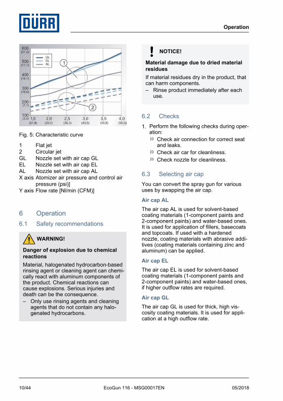
Fig. 5: Characteristic curve
1 Flat jet2 Circular jetGL Nozzle set with air cap GLEL Nozzle set with air cap ELAL Nozzle set with air cap ALX axis Atomizer air pressure and control air
pressure (psi)]Y axis Flow rate [Nl/min (CFM)]
6 Operation6.1 Safety recommendations
WARNING!
Danger of explosion due to chemicalreactionsMaterial, halogenated hydrocarbon-basedrinsing agent or cleaning agent can chemi-cally react with aluminum components ofthe product. Chemical reactions cancause explosions. Serious injuries anddeath can be the consequence.– Only use rinsing agents and cleaning
agents that do not contain any halo-genated hydrocarbons.
NOTICE!
Material damage due to dried materialresiduesIf material residues dry in the product, thatcan harm components.– Rinse product immediately after each
use.
6.2 Checks1. Perform the following checks during oper-
ation:Check air connection for correct seatand leaks.Check air car for cleanliness.Check nozzle for cleanliness.
6.3 Selecting air capYou can convert the spray gun for varioususes by swapping the air cap.
Air cap ALThe air cap AL is used for solvent-basedcoating materials (1-component paints and2-component paints) and water-based ones.It is used for application of fillers, basecoatsand topcoats. If used with a hardenednozzle, coating materials with abrasive addi-tives (coating materials containing zinc andaluminum) can be applied.
Air cap ELThe air cap EL is used for solvent-basedcoating materials (1-component paints and2-component paints) and water-based ones,if higher outflow rates are required.
Air cap GLThe air cap GL is used for thick, high vis-cosity coating materials. It is used for appli-cation at a high outflow rate.
Operation
05/2018EcoGun 116 - MSG00017EN10/44

Air cap RSThe air cap RS (round jet with nozzle protec-tion) is used for application of pickles, anti-adherents, solvents and release agents. It isnot suitable for application of lacquers andpaints.
6.4 Changing the air capPersonnel:
Operator + additional qualification explosion pro-tection
Protective equipment:Protective workwearProtective gloves
Removing the air cap
Fig. 6: Removing the air cap
1. Loosen cap nut (1).
2. Remove the air cap (1).
Assembling air cap3. Place the air cap (1).
4. Align the air cap as required Ä 6.5“Alignment of the air cap”.
5. Tighten cap nut (1).
6.5 Alignment of the air capPersonnel:
Operator + additional qualification explosion pro-tection
Protective equipment:Protective workwearProtective gloves
The position of the air cap determines thealignment of the spray pattern.
Fig. 7: Air cap alignment
1. Lightly loosen cap nut (2).
2. Turn the air cap (1) as required for thedesired spray pattern.
3. Tighten cap nut (2) by hand.
Operation
05/2018 EcoGun 116 - MSG00017EN 11/44

6.6 Guiding the spray gunPersonnel:
Operator + additional qualification explosion pro-tection
Protective equipment:Protective glovesSafety bootsProtective workwearEye protectionRespiratory protection deviceUse ear protection
Fig. 8: Guiding the paint gun
1. Guide the spray gun as follows:Guide spray gun at 90 degrees to thesurface.Maintain a distance of 15 to max.25 cm to the surface.
The distance can vary for effectcoatings.
6.7 Rinsing6.7.1 Safety recommendations
NOTICE!
Material damage due to unsuitablerinsing agentIf the rinsing agent reacts chemically withthe components or the material, compo-nents get damaged.– Use only the rinsing agents that are
compatible with the components andthe material.
– Refer to safety data sheet of materialmanufacturer.
6.7.2 General notesWhen rinsing, use fluid to remove innersoiling from components.
6.7.3 Rinsing spray gunPersonnel:
Operator + additional qualification explosion pro-tection
Protective equipment:Use ear protectionEye protectionRespiratory protection deviceProtective workwearProtective gloves
Rinsing spray gun:After end of workBefore every change of materialPrior to cleaningPrior to dismantlingBefore a long time of non-useBefore placing in storage
Operation
05/2018EcoGun 116 - MSG00017EN12/44

Additional rinsing intervals dependon the material used.
Preparation for rinsing1. Disconnect the air hose from the spray
gun.
Fig. 9: Removing the air cap
2. Loosen cap nut (1).
3. Remove the air cap (1).
Purging4. Keep collecting tray ready.
Fig. 10: Rinsing spray gun
5. Keep the spray gun slightly at an angleabove the collecting tray, nozzle (3)pointing towards the ground.
6. Rinse the spray gun with an appropriaterinsing agent through the material con-nection (2), until the rinsing agent runsclean without any material residue. Use abrush to carefully clean the holes (3) ofthe nozzle.
7. Ensure proper disposal of the exitingmaterial and rinsing agent.
8. Connect the compressed air hose to thespray gun.
9. Operate trigger lever until no more rinsingagent flows out.
Final work10. Place the air cap (1).
11. Tighten cap nut (1).
Operation
05/2018 EcoGun 116 - MSG00017EN 13/44

7 Cleaning and maintenance7.1 Safety recommendations
WARNING!
Danger of fire and explosionFlammable coating materials and theirdetergents and cleaning agents can causea fire or an explosion.– Ensure that the flashpoint of the fluid is
at least 15 K above the ambient tem-perature.
– Note explosion group of the fluid.– Follow safety data sheets.– Ensure that forced ventilation and fire
protection equipment are in operation.– Do not use sources of ignition and
open light.– Do not smoke.
WARNING!
Risk of injury from unsuitable replace-ment parts in explosive areas.Replacement parts not compliant with thespecifications of the ATEX guidelines cancause explosions in an explosive atmos-phere. Serious injuries and death can bethe consequence.– Use exclusively original replacement
parts.
WARNING!
Danger to health from harmful or irri-tant substancesContact with hazardous liquids or vapors,can result in serious injury or death.– Ensure that the forced ventilation is
operational.– Follow safety data sheets.– Wear specified protective clothing.
WARNING!
Risk of injury due to escaping materialand compressed airEscaping compressed material can causeserious injury.Before carrying out any work:– Disconnect the system, in which the
spray gun is installed, from com-pressed air and material supply.
– Secure the system against reconnec-tion.
– Relieve the lines.
WARNING!
Danger of explosion due to chemicalreactionsMaterial, halogenated hydrocarbon-basedrinsing agent or cleaning agent can chemi-cally react with aluminum components ofthe product. Chemical reactions cancause explosions. Serious injuries anddeath can be the consequence.– Only use rinsing agents and cleaning
agents that do not contain any halo-genated hydrocarbons.
CAUTION!
Risk of injury due to spring tensionThe set screw of the spray gun is underspring tension. If you remove the setscrew, the spring tension could cause theset screw to jump out unexpectedly andcause light injuries.– Remove and install set screw.
Cleaning and maintenance
05/2018EcoGun 116 - MSG00017EN14/44

NOTICE!
Unsuitable cleaning agentsUnsuitable cleaning agents can damagethe product.– Only use cleaning agents approved by
the material manufacturer.– Follow safety data sheets.– Place heavily soiled components in a
cleaning bath.– Only place those parts in the
cleaning bath, which are suitable forthe cleaning bath.
– Use only electrically conductivecontainers.
– Ground the container.– Do not use ultrasound baths.
Use alcohols (isopropanol, butanol) fornon-flammable coating materials.Remove dried non-flammable coatingmaterials using a material manufacturer-approved organic thinner.When cleaning with flammable detergent,do not spray into a closed container. Anexplosive gas-air mixture can form insideclosed containers.
NOTICE!
Damage due to unsuitable cleaningtoolsUnsuitable cleaning tools can damage theproduct.– Only use cloths, soft brushes and
paintbrushes.– Do not use abrasive cleaning tools.– Do not poke blocked nozzles with met-
allic objects.– Do not use compressed air for
cleaning.– Do not use any thinner spray guns.– Do not use high pressure for cleaning
agents.
7.2 CleaningPersonnel:
Operator + additional qualification explosion pro-tection
Protective equipment:Use ear protectionEye protectionRespiratory protection deviceProtective workwearProtective gloves
1. Rinse the spray gun Ä 6.7 “Rinsing”.
2. Disconnect the air hose from the spraygun.
3. Remove feed cup.
4. Remove material residues with a cloth ora soft brush.
5. Clean the spray gun carefully and dry itwith a soft cloth.
Clean filter of the flow cup.Personnel:
Operator + additional qualification explosion pro-tection
Protective equipment:Protective workwearProtective gloves
Depending on the configuration, the spraygun is supplied with a filter.
Cleaning and maintenance
05/2018 EcoGun 116 - MSG00017EN 15/44

For a thorough cleaning, you can remove thefilter.
Disassembling
Fig. 11: Cleaning filter
1. Pull out filter (1) on the holding pin fromthe material connector.
2. Clean filter (1) in the cleaning bath.
3. Insert filter (1) in the material connectorand push down until it sits firmly.
Cleaning the air cap und nozzlePersonnel:
Operator + additional qualification explosion pro-tection
Protective equipment:Protective workwearProtective gloves
For a thorough cleaning you can remove theair cap and the nozzle.
Disassembly
Fig. 12: Disassembling the air cap andnozzle
1. Loosen cap nut (1).
2. Remove the air cap (1).
3. Push trigger lever (3) through. Keep itpressed.ðThe needle is pushed backwards so
that it will not be damaged during dis-assembly of the nozzle.
4. Unscrew and remove nozzle (2) usingmonkey wrench.
5. Release trigger lever (3).
6. Clean air cap (1) using cleaning agentand cleaning brush Ä 11.2 “Tools”.
7. Wipe the cleaned air cap dry with a cloth.
8. Clean nozzle (2) in the cleaning bath.
9. Clean nozzle seat with a cloth or a softbrush.
Assembling10. Push trigger lever (3) through. Keep it
pressed.ðThe needle is pushed backwards so
that it will not be damaged duringassembly of the nozzle.
Cleaning and maintenance
05/2018EcoGun 116 - MSG00017EN16/44

11. Insert and tighten nozzle (2). Tightening torque: 10 Nm
12. Release trigger lever (3).
13. Place the air cap (1).
14. Tighten cap nut (1).
7.3 Maintenance7.3.1 Maintenance scheduleThe maintenance intervals given below are based on experiential values. Adjust maintenanceintervals individually to increased requirements.
Interval Maintenance work
After each use Clean Ä 7.2 “Cleaning”.
Daily Check state and tightness of the spray gun as well as of the connectionsand lines.
Weekly Lubricate lever bearing Ä 7.3.2 “Lubrication”.
7.3.2 LubricationThe following components must be lubri-cated with a silicone-free grease:
O-rings and sealsBearingSet screw and threadsNeedle glandLever bearing
Lubricate internal components at thetime of maintenance work, whichinclude disassembly of the con-cerned components any way.Recommended lubricant: SYN-THESO GLEP 1 Ä 10.8 “Operatingand auxiliary materials”
8 Faults8.1 Safety recommendations
NOTICE!
Property damage due to improperreplacement of needle and nozzleReplacing only the needle or only thenozzle could damage spray gun compo-nents. This can compromise the tightnessof the spray gun. The spray pattern deteri-orates.– Observe order of replacement steps
(needle – nozzle).– Observe order of assembly steps
(nozzle – needle).– Always replace nozzle and needle at
the same time.
Faults
05/2018 EcoGun 116 - MSG00017EN 17/44

NOTICE!
Property damage due to improper han-dlingMechanical load can damage needle andnozzle.– Handle with care during installation
and dismantling.
– Do not subject the needle to anymechanical pressure.
– Avoid collisions of components to beassembled and disassembled with theneedle.
– Do not excessively tighten compo-nents.
Faults
05/2018EcoGun 116 - MSG00017EN18/44

8.2 Defects tableVisualizer of typical spray pattern problems
Spray pattern Fault identification
Spray jet is distorted.
Spray jet is bent or tapered.
Spray jet is too thick in the middle.
Spray jet is split.
Spray jet is uneven.
Fault description Cause Remedy
No material Feed cup empty Check feed cup. Top up, if necessary.
Air pressure too high(only when using anextension)
Decrease the air pressure via the totalair control.
Material escapes at theneedle gland.
Needle gland worn out Replace needle gland Ä 8.3.3“Replace needle gland”.
Needle gland loose Tighten needle gland sensitively.
Air escapes between valvepin and housing.
Valve seal worn out. Replace valve seal Ä 8.3.2“Replacing valve seal”.
Faults
05/2018 EcoGun 116 - MSG00017EN 19/44

Fault description Cause Remedy
Spray jet is distorted. Air cap is misaligned. Rotate air cap into the required posi-tion. Ä 6.5 “Alignment of the air cap”
Spray jet is bent or tapered. Bores in air cap aresoiled.
Clean and check air cap. Replace aircap if defective Ä 7.2 “Cleaning”.
Nozzle seat soiled. Cleaning the nozzle seat Ä 7.2“Cleaning”.
Nozzle soiled ordefective.
Clean and check the nozzle. If nozzleis defective, replace it along with theneedle Ä 8.3.1 “Replace needle andnozzle.”.
Spray jet is too thick in themiddle.
Material too viscous. Change material consistency.
Horn air pressure toolow
Decrease the horn air pressure via theflat jet control.
Air pressure too low Increase the air pressure via the totalair control.
Spray jet is split. Material too thin. Change material consistency.
Horn air pressure toohigh
Decrease the horn air pressure via theflat jet control.
Air pressure too high Decrease the air pressure via the totalair control.
Spray jet is uneven. Thespray pattern quality is bad.
Nozzle soiled ordefective.
Clean and check the nozzle. If nozzleis defective, replace it along with theneedle Ä 8.3.1 “Replace needle andnozzle.”.
Cap nut or nozzle isnot properly tightened.
Tighten cap nut and nozzle Ä “Cleaning the air cap und nozzle”.
Needle gland worn out Replace needle gland Ä 8.3.3“Replace needle gland”.
Faults
05/2018EcoGun 116 - MSG00017EN20/44

8.3 Troubleshooting8.3.1 Replace needle and nozzle.
The disassembly and assembly ofneedle for the common gun versionare described in the section called“Standard version”.The version of the spray gun with aircap GL and 4.0 mm nozzle is disas-sembled and assembled in a dif-ferent manner. Follow the relevantsection.
Standard versionPersonnel:
Operator + additional qualification explosion pro-tection
Protective equipment:Protective workwearProtective gloves
Disassembling
Fig. 13: Disassemble needle and nozzle(standard version).
1. Thread off and remove set screw (5).
2. Push trigger through.ðThe needle (3) is pushed a little back-
wards and out from the housing.
3. Remove bearing and needle spring (4).
4. Remove the needle (3).
5. Loosen cap nut (1).
6. Remove the air cap (1).
7. Unscrew and remove nozzle (2) usingmonkey wrench.
8. Replace worn out or defective compo-nents.
Assembling9. Insert and tighten nozzle (2).
Tightening torque: 10 Nm
10. Place the air cap (1).
11. Tighten cap nut (1).
12. Push in needle (3) carefully into thehousing.
13. Push needle spring and bearing (4) onthe needle.
14. Set and thread-in set screw (5).
Faults
05/2018 EcoGun 116 - MSG00017EN 21/44

Version with air cap GL and 4.0 mmnozzlePersonnel:
Operator + additional qualification explosion pro-tection
Protective equipment:Protective workwearProtective gloves
Disassembling
Fig. 14: Disassemble needle and nozzle.
1. Thread off and remove set screw (4).
2. Remove bearing and needle spring (3).
3. Loosen cap nut (1).
4. Remove the air cap (1).
5. Unscrew nozzle (2) using monkey wrenchand remove.
Fig. 15: Disassembling Needle
6. Secure needle (6) on the wrench mountin the center of the spray gun using themonkey wrench before twisting.
7. Loosen the needle tip (5) using an instal-lation wrench.
8. Push trigger through.ðThe needle (6) is pushed a little back-
wards and out from the housing.
9. Remove needle (6).
10. Replace worn out or defective compo-nents.
Assembling11. Push in needle (6) carefully into the
housing.
12. Secure needle (6) on the wrench mountin the center of the spray gun using themonkey wrench before twisting.
13. Insert needle tip (5). Tighten using theinstallation wrench.
14. Insert and tighten nozzle (2).Tightening torque: 10 Nm
15. Place the air cap (1).
16. Tighten cap nut (1).
Faults
05/2018EcoGun 116 - MSG00017EN22/44

17. Push needle spring and bearing (3) onthe needle.
18. Set and thread-in set screw (4).
8.3.2 Replacing valve sealPersonnel:
Operator + additional qualification explosion pro-tection
Protective equipment:Protective workwearProtective gloves
Disassembling1. Disassemble air cap, nozzle and needleÄ 8.3.1 “Replace needle and nozzle.”.
Fig. 16: Disassemble valve seal
2. Thread off bushing (4).
3. Remove the compression spring (2).
4. To replace the O-ring (3), lever out the O-ring (3) from the housing using a sharpobject.
5. Push trigger through.
ðThe valve pin (1) is pushed a littlebackwards and out from the housing.
6. Remove valve pin (1).
Fig. 17: Disassemble seal of the bushing.
7. Insert the assembly plug (6) in thebushing (4).
8. Screw-in set screw (7) in the bushing (4)using the assembly plug (6).ðThe seal (5) is pushed out from the
bushing (4).
Faults
05/2018 EcoGun 116 - MSG00017EN 23/44

Fig. 18: Disassemble seal
9. Push in assembly plug (6) carefully intothe gun housing behind the trigger lever.The contact surface of the assembly plugmust point in the direction of the triggerlever.
10. Push in installation wrench (8) carefullyinto the gun housing from the back.
11. Push in dismantled needle (9) throughthe installation wrench (8) into the gunhousing.
12. Push trigger through.ðThe seal on the inside is pushed on
installation wrench (8).
13. Pull out needle (9).
Fig. 19: Disassemble seal
14. Pull out installation wrench (8) with seal(10).
15. Pull out assembly plug (6).
16. Replace worn out or defective compo-nents.
Assembling17. Push seal (10) on the installation
wrench.
18. Push in installation wrench (8) with seal(10) from behind into the housing.Press-in seal.
19. Pull out installation wrench (8).ðThe seal (10) remains in the housing.
Faults
05/2018EcoGun 116 - MSG00017EN24/44

Fig. 20: Assemble seal of the bushing.
20. Push seal (5) on the installation wrench(8).
21. Insert the installation wrench (8) withseal into the bushing (4). Press-in seal.
22. Pull out installation wrench (8).ðThe seal (5) remains in the bushing
(4).
23. Insert valve pin (1).
24. Press-in O-ring (3) into the housing.
25. Insert the compression spring (2).
26. Screw-in bushing (4) into the housing.
27. Install nozzle and needle Ä 8.3.1“Replace needle and nozzle.”.
8.3.3 Replace needle glandPersonnel:
Operator + additional qualification explosion pro-tection
Protective equipment:Protective workwearProtective gloves
Disassembling1. Remove needle Ä 8.3.1 “Replace needle
and nozzle.”.
Fig. 21: Disassemble gland bolt
2. Loosen gland bolt (1) and remove it.
Fig. 22: Disassemble needle packing
3. Remove needle gland (2) with springguide (3) and gland spring (4).
Faults
05/2018 EcoGun 116 - MSG00017EN 25/44

4. Replace worn out or defective compo-nents.
Assembling5. See that the alignment of the
components to be installed is cor-rect.
Push in needle carefully into the housing,until the needle tip comes out in the areaof the trigger.
6. String gland bolt (1).
7. String gland spring (4).
8. String spring guide (3).
9. String needle gland (2).
10. Tighten gland bolt (1) sensitively.
If there are leakages in opera-tion after you replace the needlegland seal, you have to tightenthe needle gland seal a littlemore.
11. Install needle Ä 8.3.1 “Replace needleand nozzle.”.
9 Disassembly and Disposal9.1 Safety recommendations
WARNING!
Risk of injury due to escaping materialand compressed airEscaping compressed material can causeserious injury.Before carrying out any work:– Disconnect the system, in which the
spray gun is installed, from com-pressed air and material supply.
– Secure the system against reconnec-tion.
– Relieve the lines.
9.2 DisassemblyPersonnel:
Operator + additional qualification explosion pro-tection
Protective equipment:Use ear protectionEye protectionRespiratory protection deviceProtective workwearProtective gloves
1. Rinse the spray gun Ä 6.7 “Rinsing”.
2. Disconnect the compressed air supplyand material feed. Secure against recon-nection.
3. Disconnect all lines.
9.3 Disposal
ENVIRONMENT!
Incorrect disposalImproper waste disposal threatens theenvironment and prevents re-use andrecycling.– Always dispose of components in
accordance with their characteristic.Ä 10.7 “Materials used”
– Collect leaked out operating and auxil-iary materials completely.
– Dispose of operating and auxiliarymaterials according to the disposalprovisions in force.
– In case of doubt, refer to the local dis-posal authorities.
Disassembly and Disposal
05/2018EcoGun 116 - MSG00017EN26/44

10 Technical data10.1 Dimensions and weight
Detail Value
Weight (without flowcup)
480 g
Nozzle diameter(with AL air cap)
1.0 to 2.2 mm
Nozzle diameter(with EL air cap)
2.8 mm
Nozzle diameter(with GL air cap)
4.0 mm
Nozzle diameter(with RS air cap)
1.5 mm
10.2 Connections
Connection Nominal width
Material G3/8”/M 16 x 1.5
Air 1/4” (for BSPthreads and NPSM
threads)
10.3 Operating conditions
Detail Value
Maximum allowable mate-rial temperature whenoperating with protectivegloves
40 °C
Maximum allowable mate-rial temperature whenoperating with heat-resistant protective gloves
60 °C
10.4 Emissions
Detail Value
Emission sound pressurelevel LpA, A – according toEN 14462
86 dB
Detail Value
Uncertainty KpA 5 dB
Sound power level LWA, A ֪– according to EN14462
99.8 dB
Uncertainty KWA 5 dB
10.5 Operating values
Detail Value
Max. air pressure 4 bar
Air pressure, optimum 2 to 3 bar
10.6 Type plateThe type plate is placed on the housing andfeatures the following details:
Product designationMaterial numberYear of manufactureSerial numberEX labelingManufacturerCE labeling
10.7 Materials used
Component Material
Housing Nickel plated alu-minum
Compressionsprings
Stainless steel
Materials in contactwith material
Stainless steel,nickel plated alu-minum
Seals in contactwith material
PTFE
Seals without mate-rial contact
PE, PTFE
Technical data
05/2018 EcoGun 116 - MSG00017EN 27/44
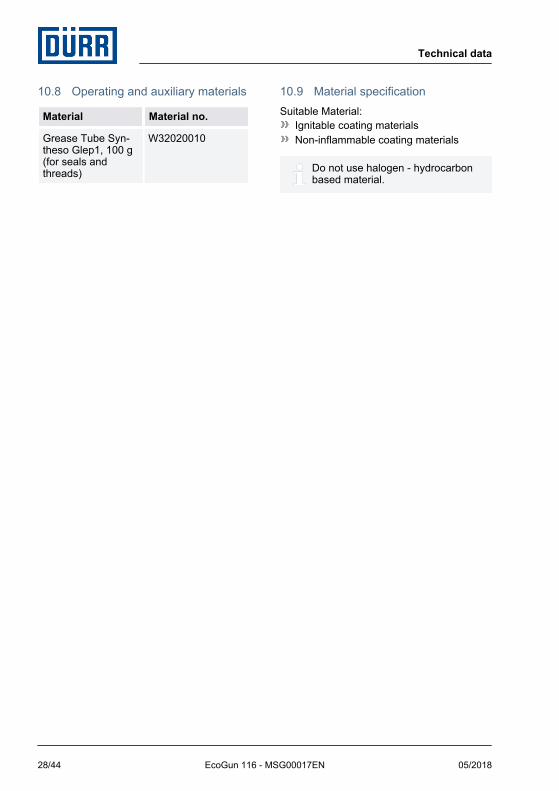
10.8 Operating and auxiliary materials
Material Material no.
Grease Tube Syn-theso Glep1, 100 g(for seals andthreads)
W32020010
10.9 Material specificationSuitable Material:
Ignitable coating materialsNon-inflammable coating materials
Do not use halogen - hydrocarbonbased material.
Technical data
05/2018EcoGun 116 - MSG00017EN28/44

11 Replacement parts, tools and accessories11.1 Replacement parts
Fig. 23: Exploded view
Replacement parts, tools and accessories
05/2018 EcoGun 116 - MSG00017EN 29/44

Item Description Quan-tity
Material no.
1 Air cap 1 Ä “Overview - Aircaps and nozzles”
2 Nozzle 1
3 O-ring 33.3x1.6 1 M08030814
4 O-ring 10x1 1 M08030866
5 Housing 1
6 O-Ring 8.4 x 1.78 1
7 Material connection G3/8'' 1
8 Filter 1 M13010029
9 Feed cup plastic G 3/8" with filter, 600 ml 1 N08010034
Feed cup aluminum G3/8'', 750 ml 1 N08010035
Feed cup plastic G 3/8" with filter, 125 ml 1 N08010032
10 Material connection M 16 x 1.5 1
11 Feed cup plastic M16 x 1.5 with filter, 600 ml 1 N08010040
12 Seal, black 2 M08280057
13 Valve seat 1 M35010264
14 Valve pin 1 M49150003
15 Valve pin spring 1
16 O-ring 13 x 1 1 M08030864
17 Bushing 1
18 Needle gland 1 M08320005
19 Spring guide 1
20 Gland spring 1
21 Gland bolt 1
22 Needle 1 Ä “Overview - Aircaps and nozzles”
23 Needle spring 1
24 Bearing 1
25 Set screw 1 M41260004
Replacement parts, tools and accessories
05/2018EcoGun 116 - MSG00017EN30/44

Item Description Quan-tity
Material no.
26 Trigger screw 1
27 Trigger 1
28 Trigger pin 1
29 Air flow control 1 M21200006
30 Air connection 1/4'' 1 M01200004
31 Push-on nipple for quick-action coupling 1 Ä 11.3 “Accessories”
32 Push-on nipple for quick-action coupling 1
33 Control screw 1
34 Seal 1 M08280040
35 Bushing 1
36 Rotary control 1
37 Color ring (blue) 1
38 Screw 1
Overview - Air caps and nozzles
Nozzle sets consist of needle and nozzle with or without air cap.
Nozzle sets with air cap AL
Nozzle diameter Item no. Material no.
1.0 mm 1, 2, 22 M09800148
1.2 mm M09800149
1.3 mm M09800150
1.4 mm M09800151
1.6 mm M09800152
1.8 mm M09800153
2.0 mm M09800154
2.2 mm M09800155
1.4 mm* M09800156
Replacement parts, tools and accessories
05/2018 EcoGun 116 - MSG00017EN 31/44

Nozzle diameter Item no. Material no.
1.8 mm* M09800157
2.2 mm* M09800158
* - Nozzle and needle hardened.
Nozzle sets with air cap EL
Nozzle diameter Item no. Material no.
2.8 mm 1, 2, 22 M09800165
Nozzle sets with air cap GL
Nozzle diameter Item no. Material no.
4.0 mm 1, 2, 22 M09800166
Nozzle sets with air cap RS
Nozzle diameter Item no. Material no.
1.5 mm 1, 2, 22 M09800402
Nozzle sets without air cap
Nozzle diameter Suitable for air cap Item no. Material no.
1.0 mm AL 2, 22 M09800246
1.2 mm AL M09800247
1.3 mm AL M09800248
1.4 mm AL M09800249
1.5 mm RS M09800403
1.6 mm AL M09800251
1.8 mm AL M09800252
2.0 mm AL M09800254
2.2 mm AL M09800255
1.4 mm* AL M09800250
1.8 mm* AL M09800253
2.2 mm* AL M09800256
Replacement parts, tools and accessories
05/2018EcoGun 116 - MSG00017EN32/44

Nozzle diameter Suitable for air cap Item no. Material no.
2.8 mm EL M09800257
4.0 mm GL M09800258
* - Nozzle and needle hardened.
Air caps
Air cap type Item no. Material no.
AL 1 M35030162
EL M35030163
GL M35030164
RS M35030181
Valve set N36960105
Description Item no. Quantity
Valve pin 14 1
Seal, black 12 2
O-ring 13 x 1 16 1
Assembly plug - 1
Repair kit needle seal N36960023
Description Item no. Quantity
Needle gland 18 1
Spring guide 19 1
Gland spring 20 1
Gland bolt 21 1
Seal set nozzle and air cap N36960109
Description Item no. Quantity
O-ring 33.3x1.6 3 1
O-ring 10x1 4 1
O-Ring 8.4 x 1.78 6 1
Replacement parts, tools and accessories
05/2018 EcoGun 116 - MSG00017EN 33/44

Trigger lever set N36960106
Description Item no. Quantity
Trigger screw 26 1
Trigger 27 1
Trigger pin 28 1
Closure set N369600107
Description Item no. Quantity
Needle spring 23 1
Bearing 24 1
Set screw 25 1
Flat jet control set (blue color ring) N369600108
Description Item no. Quantity
Control screw 33 1
Seal 34 1
Bushing 35 1
Rotary control 36 1
Color ring (blue) 37 1
Screw 38 1
Material connection set G3/8'' N36960133
Description Item no. Quantity
O-Ring 8.4x1.78 6 1
Material connection G3/8'' 7 1
Material connection set M 16 x 1.5 N36960137
Description Item no. Quantity
O-Ring 8.4x1.78 6 1
Material connection M 16 x 1.5 10 1
Replacement parts, tools and accessories
05/2018EcoGun 116 - MSG00017EN34/44

11.2 Tools
Fig. 24: Tools
Tool kit N36960045
Description Item no. Quantity
Cleaning brush 1 1
Monkey wrench 2 1
Installation wrench 3 1
Assembly rod 4 1
Tool kit (2 parts) N36960184
Description Item no. Quantity
Cleaning brush 1 1
Monkey wrench 2 1
Replacement parts, tools and accessories
05/2018 EcoGun 116 - MSG00017EN 35/44

11.3 Accessories
A complete overview of the accessories is available from the Dürr Webshop.
Description Item no. Quan-tity
Material no.
Color ring set (red, yellow, green, blue, black) 37 5 N36960088
Cleaning set 21 parts - 1 N36960038
Quick change coupling for air G1/4”-externalthreads
- 1 N40030046
Push-on nipple for quick-action coupling
Description Item no. Material no.
Push-on nipple for quick-action coupling, fixed D7.2 d10/12(EU)
31 M01010185
Push-on nipple for quick-action fixed D5 d8/11 (US) M01010186
Push-on nipple for quick-action coupling, fixed D7.5 d11/13(ASIA)
M01010187
Push-on nipple for quick-action coupling, pivoted and rotat-able D7,2 d10/12
32 M01300006
Push-on nipple for quick-action coupling, pivoted and rotat-able D5 d8/11 (US)
M01300005
Push-on nipple for quick-action coupling, pivoted and rotat-able D7,5 d11/13 (ASIA)
M01300007
Replacement parts, tools and accessories
05/2018EcoGun 116 - MSG00017EN36/44

Extensions overview
Extension Spray pattern Spray jet shape
NP Round forward
NS Round, deviating 20° from the exten-sion axis
LPS Round forward
360 degrees round jet
Description Length Externaldiameter
Weight Nozzlediameter
Material no.
Extension NP250-8
250 mm 8 mm 300 g 1.0 mm M19140014
Extension NS250-8
M19140015
Extension NP250-10
10 mm 320 g 1.2 mm M19140016
Extension NS250-10
M19140017
Extension LPS300
300 mm 18 mm 230 g 2.2 mm M19140010
Replacement parts, tools and accessories
05/2018 EcoGun 116 - MSG00017EN 37/44

Extension NP 250-8/-10 M19140014/M19140016 and NS 250-8/-10 M19140015/M19140017
Fig. 25: Extension NP/NS
Item Description Material no.
1 Cap nut
2 Sealing ring Ø36.5xØ32.7x1
3 Locknut
4 Housing
5 Seal Ø33.7xØ30.6x1
6 Tube external
7 Inner tube with nozzle
Replacement parts, tools and accessories
05/2018EcoGun 116 - MSG00017EN38/44

Item Description Material no.
8 Seal
9 Screw bit
10 Ball sealer
11 Needle
12 Cleaning brush Ä 11.2 “Tools”
Assembly instructions– Disassemble air cap, nozzle and needle. Ä 8.3.1 “Replace needle and nozzle.”– Thread the ball sealer (10).– Turn in and tighten screw bit (9) with pre-assembled seal (8) and pre-assembled
inner tube with nozzle (7) into the gun.– Push housing (4) with seal (5), pre-assembled outer tube(6) and locknut (3) on to the
inner tube (7).– Fit and tighten cap nut (1) with sealing ring (2).– Set outer tube (6).
The outer tube (6) is adjustable and allows varying setting positions of the air capto the nozzle. The farther the nozzle projects over the front side of the air cap, thebroader is the spray jet. Projection of the nozzle above the air cap should be min-imal.
– Tighten the locknut (3).– Push in needle (11) carefully into the gun housing from the back.– Insert needle spring, bearing and set screw again. Ä 8.3.1 “Replace needle and
nozzle.”– Purge the gun with solvent. Ä 6.7 “Rinsing”– Set the material flow. Ä 5 “Commissioning”
Nozzle set NP/NS 250-8 M09800433
Description Item no. Quantity
Inner tube with nozzle 7 1
Seal 8 1
Needle 11 1
Replacement parts, tools and accessories
05/2018 EcoGun 116 - MSG00017EN 39/44

Nozzle set NP/NS 250-10 M09800434
Description Item no. Quantity
Inner tube with nozzle 7 1
Seal 8 1
Needle 11 1
Seal set for Extension NP/NS N36960181
Description Item no. Quantity
Sealing ring Ø36.5xØ32.7x1 2 1
Seal Ø33.7xØ30.6x1 5 1
Seal 8 1
Ball sealer 10 1
Replacement parts, tools and accessories
05/2018EcoGun 116 - MSG00017EN40/44
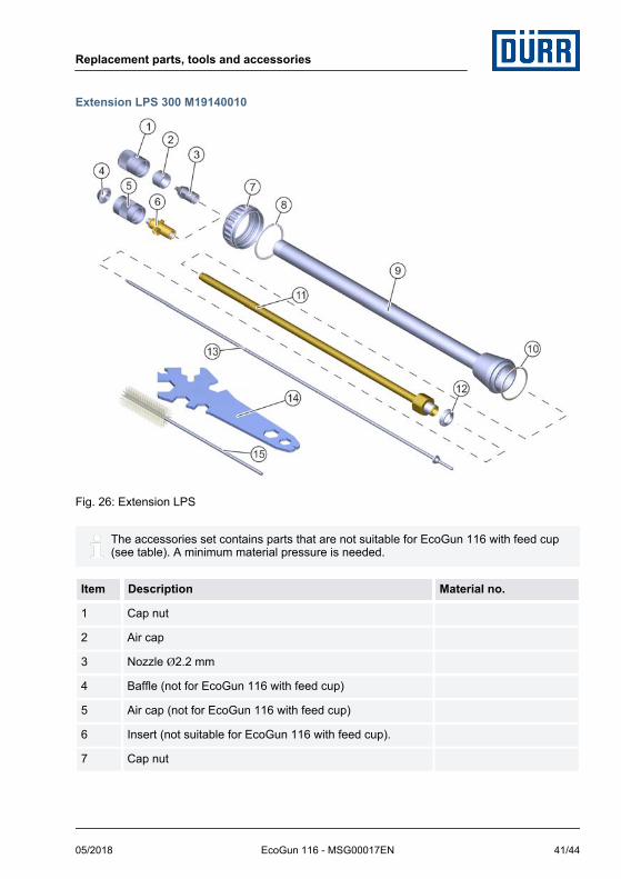
Extension LPS 300 M19140010
Fig. 26: Extension LPS
The accessories set contains parts that are not suitable for EcoGun 116 with feed cup(see table). A minimum material pressure is needed.
Item Description Material no.
1 Cap nut
2 Air cap
3 Nozzle Ø2.2 mm
4 Baffle (not for EcoGun 116 with feed cup)
5 Air cap (not for EcoGun 116 with feed cup)
6 Insert (not suitable for EcoGun 116 with feed cup).
7 Cap nut
Replacement parts, tools and accessories
05/2018 EcoGun 116 - MSG00017EN 41/44

Item Description Material no.
8 Sealing ring Ø36.5xØ32.7x1
9 Outer tube
10 Seal Ø33.7xØ30.6x1
11 Inner tube 300 mm M34010602
12 Ball sealer
13 Needle
14 Monkey wrench Ä 11.2 “Tools”
15 Cleaning brush
Assembly instructions– Disassemble air cap, nozzle and needle. Ä 8.3.1 “Replace needle and nozzle.”– Thread the ball sealer (12). Tighten the gun tight using the inner tube (11).– Push up outer tube (9) with seal (10).– Thread on and tighten cap nut (7) with sealing ring (8).– Insert and tighten nozzle (3).– Insert air cap (2). Tighten cap nut (1).– Push in needle (13) carefully into the gun housing from the back.– Insert needle spring, bearing and set screw again. Ä 8.3.1 “Replace needle and
nozzle.”– Purge the gun with solvent. Ä 6.7 “Rinsing”– Set the material flow. Ä 5 “Commissioning”
Nozzle set C for LPS 300 M09800444
Description Item no. Quantity
Baffle 4 1
Air cap 5 1
Insert 6 1
Needle 13 1
Nozzle set R for LPS 300 M09800438
Description Item no. Quantity
Cap nut 1 1
Air cap 2 1
Replacement parts, tools and accessories
05/2018EcoGun 116 - MSG00017EN42/44

Description Item no. Quantity
Nozzle 3 1
Needle 13 1
Seal set for extension LPS N36960183
Description Item no. Quantity
Sealing ring Ø36.5xØ32.7x1 8 1
Seal Ø33.7xØ30.6x1 10 1
Ball sealer 12 1
11.4 Order
WARNING!
Risk of injury from unsuitable replace-ment parts in explosive areas.Replacement parts not compliant with thespecifications of the ATEX guidelines cancause explosions in an explosive atmos-phere. Serious injuries and death can bethe consequence.– Use exclusively original replacement
parts.
Ordering replacement parts, tools andaccessories as well as information on prod-ucts that are listed without order number.Ä “Hotline and Contact”
Replacement parts, tools and accessories
05/2018 EcoGun 116 - MSG00017EN 43/44

Translation of the original operation manual
Dürr Systems AGApplication Technology
Carl-Benz-Str. 3474321 Bietigheim-Bissingen
Germanywww.durr.com
Phone +49 7142 78-0
Transmission and duplication of this document, as well as use and sharing of its contents are notpermitted without express written approval. Violations will be liable for compensation for damages.
All rights in the event of a patent grant or design registration are reserved.
© Dürr Systems AG 2017
www.durr.com