ecoc 2015 workshop slides
TRANSCRIPT

Low loss hollow core optical fibers: Implications for system design and DSP
V.A.J.M. (Vincent) Sleiffer ECOC 2015, Valencia, Sept 27th – Oct 1st
Sunday 27 Sept, WS: How should we…?, Room Malvarossa, 16:00 - 18:00


Why hollow core photonic band gap fibers?
Optical signal mainly propagates in air rather than glass (SiO2), resulting in three main benefits:
Virtually no nonlinear distortion Ultra low Rayleigh scattering, potential for ultra low loss transmission medium (@ 2 μm) neff close to 1, resulting in a ~1.5 μs/km latency reduction compared to glass fibers
Try to achieve propagation of the optical signal in air as much as possible!

Ultimate low loss of HCF
• Mode field overlap with cladding increases moving longer wavelengths. Ultimately infrared absorption limited.
Depending on fraction optical signal travelling in air!
P.J. Roberts et al., “Ultimate low loss of hollow-core photonic crystal fibres”, in Opt. Exp., Vol. 13, No. 1, pp. 236-244 (2005).
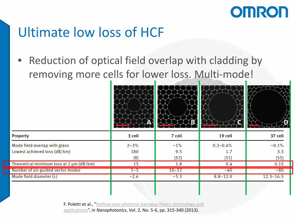
Ultimate low loss of HCF
F. Poletti et al., “Hollow-core photonic bandgap fibers: technology and applications”, in Nanophotonics, Vol. 2, No. 5-6, pp. 315-340 (2013).
• Reduction of optical field overlap with cladding by removing more cells for lower loss. Multi-mode!

Single mode transmission challenges (@ 1550nm) • Large analogy with current transmission systems
– Same technology for transmitters, receivers, amplifiers, and WSS/ROADMs can be employed
• Big differences – Fiber loss has to be solved – No non-linear compensation required! – Mode-field diameter mismatch
– Impulse response?

Single-mode transmission – Impulse response (@ 1550 nm) Th.1.2.4 • 10:00-10:15: Maxim Kuschnerov et al., “Data Transmission through up to 74.8 km of Hollow-Core Fiber with Coherent and Direct-Detect Transceivers”
-1230 -820 -410 0 410 820 1230-60
-40
-20
0
Tap number
Mag
nitu
de [
dB] 7 Loops (43.4 km)
3 Loops (18.2 km)1 Loop (6.2 km)
128Gb/s DP-QPSK
Modal crosstalk increases impulse response
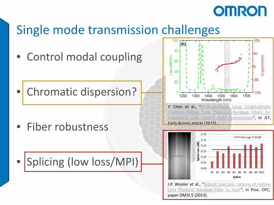
Single mode transmission challenges
• Control modal coupling
• Chromatic dispersion?
• Fiber robustness
• Splicing (low loss/MPI)
Y. Chen et al., “Multi-kilometer Long, Longitudinally Uniform Hollow Core Photonic Bandgap Fibers for Broadband Low Latency Data Transmission”, in JLT, Early Access article (2015).
J.P. Wooler et al., “Robust Low Loss Splicing of Hollow Core Photonic Bandgap Fiber to Itself”, in Proc. OFC, paper OM3I.5 (2013).
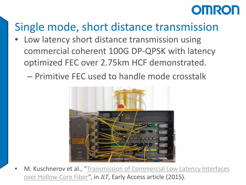
Single mode, short distance transmission • Low latency short distance transmission using
commercial coherent 100G DP-QPSK with latency optimized FEC over 2.75km HCF demonstrated. – Primitive FEC used to handle mode crosstalk
• M. Kuschnerov et al., “Transmission of Commercial Low Latency Interfaces over Hollow-Core Fiber”, in JLT, Early Access article (2015).
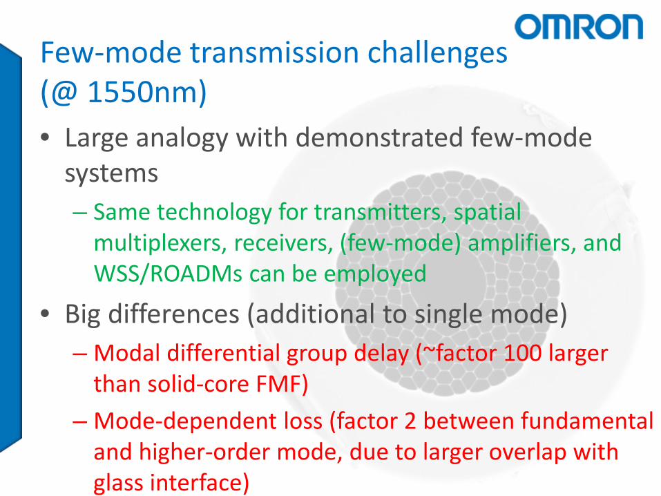
Few-mode transmission challenges (@ 1550nm) • Large analogy with demonstrated few-mode
systems – Same technology for transmitters, spatial
multiplexers, receivers, (few-mode) amplifiers, and WSS/ROADMs can be employed
• Big differences (additional to single mode) – Modal differential group delay (~factor 100 larger
than solid-core FMF) – Mode-dependent loss (factor 2 between fundamental
and higher-order mode, due to larger overlap with glass interface)

Few-mode transmission (@ 1550 nm)
• 310m 37-cell HC-PBGF
V.A.J.M. Sleiffer et al., “High Capacity Mode-Division Multiplexed Optical Transmission in a Novel 37-cell Hollow-Core Photonic Bandgap Fiber”, in JLT, Vol. 32, No. 4, pp. 854-863 (2013).
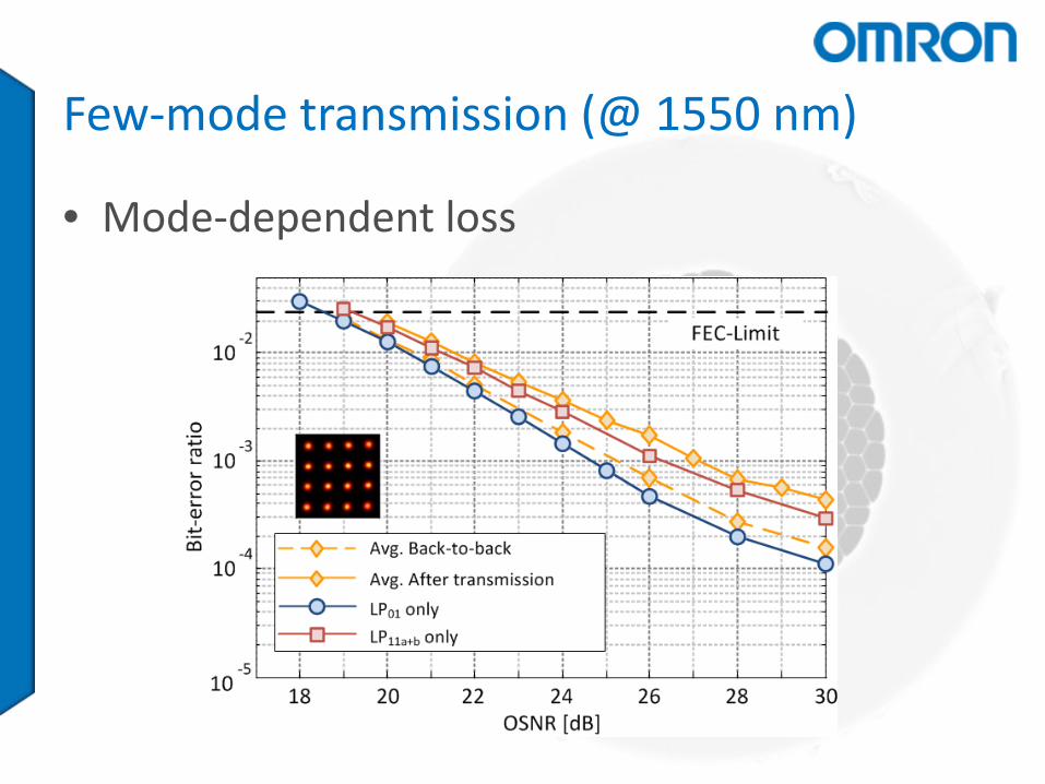
Few-mode transmission (@ 1550 nm)
• Mode-dependent loss

Few-mode transmission (@ 1550 nm)
• Large differential mode delay and unwanted coupling to other modes.
Challenges at new transmission window (@ 2 μm) • New optical components required
– Lasers – Modulators – Coherent receivers – WDM couplers – Isolators, circulators – WSS/ROADMs – Spectrum analysers

Challenges @2 μm transmission window • Thulium-doped fiber amplifier (S/C/L band)
– Analog with (FM-)EDFA but larger window (1700-2100 nm (30 THz) vs 1480-1610 nm (15 THz))
Z. Li et al., “Diode-pumped wideband thulium-doped fiber amplifiers
for optical communications in the 1800 – 2050 nm window”, in Opt. Exp., Vol. 21, No. 22, pp. 26450-55 (2013).
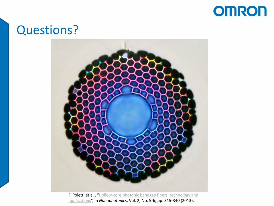
Questions?
F. Poletti et al., “Hollow-core photonic bandgap fibers: technology and applications”, in Nanophotonics, Vol. 2, No. 5-6, pp. 315-340 (2013).