ecn1123 eqn1135 hollow shaft 1ka - heidenhain
TRANSCRIPT

Product Information
ECN 1123EQN 1135
Absolute Rotary
Encoders with 1KA
Positive-Locking Hollow
Shaft for Safety-Related
Applications
02/2020

ECN 1123, EQN 1135
Rotary encoders for absolute position values with safe singleturn information
• 75A mounted stator coupling
• 1KA blind hollow shaft (Ø 6 mm) for axial clamping
= Bearing of mating shaftM1 = Measuring point for operating temperatureM2 = Measuring point for vibration1 = Contact surface of slot2 = Chamfer at start of thread is obligatory for material bonding anti-rotation lock3 = Shaft surface; ensure full-surface contact!4 = Slot required only for ECN/EQN and ECI/EQI with WELLA1 = 1KA5 = Flange surface of ECI/EQI FS; ensure full-surface contact!6 = Coupling surface of ECN/EQN7 = Maximum permissible deviation between the shaft surface and coupling surface; compensation for mounting tolerances and thermal expansion, of which ±0.15 mm of dynamic axial motion is permitted8 = Maximum permissible deviation between the shaft surface and flange surface; compensation of mounting tolerances and thermal expansion9 = Flange surface of ECI/EBI; ensure full-surface contact!10 = Undercut11 = Possible centering hole12 = 15-pin PCB connector13 = Fastening for cable with crimp sleeve; diameter: 4.3 mm ±0.1 mm; length: 7 mm14 = Positive fit element; ensure correct engagement in slot 4 (e.g., by measuring the device overhang)15 = Direction of shaft rotation for ascending position values16 = Bare; shaft coating not permitted
Required mating dimensions
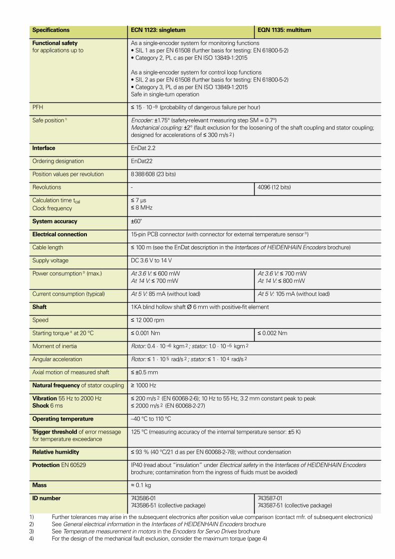
Specifications
Specifications ECN 1123: singleturn EQN 1135: multiturn
Functional safety
for applications up to
As a single-encoder system for monitoring functions
SIL 1 as per EN 61508 (further basis for testing: EN 61800-5-2)
Category 2, PL c as per EN ISO 13849-1:2015
As a single-encoder system for control loop functions
SIL 2 as per EN 61508 (further basis for testing: EN 61800-5-2)
Category 3, PL d as per EN ISO 13849-1:2015
Safe in single-turn operation
PFH ≤ 15 · 10 –9 (probability of dangerous failure per hour)
Safe position 1) Encoder: ±1.75° (safety-relevant measuring step SM = 0.7°)
Mechanical coupling: ±2° (fault exclusion for the loosening of the shaft coupling and stator coupling;
designed for accelerations of ≤ 300 m/s 2 )
Interface EnDat 2.2
Ordering designation EnDat22
Position values per revolution 8 388 608 (23 bits)
Revolutions - 4096 (12 bits)
Calculation time tcal
Clock frequency
≤ 7 µs
≤ 8 MHz
System accuracy ±60"
Electrical connection 15-pin PCB connector (with connector for external temperature sensor 3) )
Cable length ≤ 100 m (see the EnDat description in the Interfaces of HEIDENHAIN Encoders brochure)
Supply voltage DC 3.6 V to 14 V
Power consumption 2) (max.) At 3.6 V: ≤ 600 mW
At 14 V: ≤ 700 mW
At 3.6 V: ≤ 700 mW
At 14 V: ≤ 800 mW
Current consumption (typical) At 5 V: 85 mA (without load) At 5 V: 105 mA (without load)
Shaft 1KA blind hollow shaft Ø 6 mm with positive-fit element
Speed ≤ 12 000 rpm
Starting torque 4) at 20 °C ≤ 0.001 Nm ≤ 0.002 Nm
Moment of inertia Rotor: 0.4 · 10 –6 kgm 2 ; stator: 1.0 · 10 –5 kgm 2
Angular acceleration Rotor: ≤ 1 · 10 5 rad/s 2 ; stator: ≤ 1 · 10 4 rad/s 2
Axial motion of measured shaft ≤ ±0.5 mm
Natural frequency of stator coupling ≥ 1000 Hz
Vibration 55 Hz to 2000 Hz
Shock 6 ms
≤ 200 m/s 2 (EN 60068-2-6); 10 Hz to 55 Hz, 3.2 mm constant peak to peak
≤ 2000 m/s 2 (EN 60068-2-27)
Operating temperature –40 °C to 110 °C
Trigger threshold of error message
for temperature exceedance
125 °C (measuring accuracy of the internal temperature sensor: ±5 K)
Relative humidity ≤ 93 % (40 °C/21 d as per EN 60068-2-78); without condensation
Protection EN 60529 IP40 (read about “insulation” under Electrical safety in the Interfaces of HEIDENHAIN Encoders
brochure; contamination from the ingress of fluids must be avoided)
Mass ≈ 0.1 kg
ID number 743586-01
743586-51 (collective package)
743587-01
743587-51 (collective package)
1) Further tolerances may arise in the subsequent electronics after position value comparison (contact mfr. of subsequent electronics)
2) See General electrical information in the Interfaces of HEIDENHAIN Encoders brochure
3) See Temperature measurement in motors in the Encoders for Servo Drives brochure
4) For the design of the mechanical fault exclusion, consider the maximum torque (page 4)

Mounting
The blind hollow shaft of the rotary encoder is seated onto the motor's drive shaft and
fastened with a central screw. It is particularly important to ensure that the positive-locking
element of the encoder shaft securely engages the corresponding slot in the measured shaft.
The stator is connected without a centering collar to a flat surface with two clamping screws.
Use screws with material bonding anti-rotation lock (see Mounting accessories).
For the customer-side mounting design, the material properties and conditions in accordance
with the General mechanical information in the Encoders for Servo Drives brochure must be
complied with. The materials data for aluminum and steel apply both to the customer’s shaft
and stator.
For the design of the mechanical fault exclusion for the shaft connection, the following
maximum torque Mmax must be considered:
Mmax = 1.0 Nm
The customer’s mechanical design must ensure that the maximum torque Mmax occurring in
the application can be transmitted.
Mounting accessories
Screws
Screws (central screw, mounting screws) are not included in delivery and can be ordered
separately.
Screws 1) Lot size
Central screw for ECN 1123 ISO 4762-M3×22-8.8-MKL ID 202264-65
Central screw for EQN 1135 ISO 4762-M3×35-8.8-MKL ID 202264-66
10 or 100
pieces
Mounting screw for flange ISO 4762-M3×10-8.8-MKL ID 202264-87 20 or 200
pieces
1) With coating for material bonding anti-rotation lock
Please note the information on screws from HEIDENHAIN in the Encoders for Servo Drives
brochure, under the heading Screws with material bonding anti-rotation lock in the chapter
General mechanical information.
Mounting aid
To avoid damage to the cable, use the mounting aid to connect and disconnect the cable
assembly. The pulling force must be applied only to the connector of the cable assembly and
not to the wires.
ID 1075573-01
Mounting aid
This mounting aid allows the shaft of the rotary encoder to be turned from the rear of the
device, thereby making it easy to find the positive-locking connection between the encoder
shaft and the measured shaft.
ID 821017-03

Electrical Connection – Cable
Output cables inside the motor housing
With 15-pin PCB connector and 8-pin M12 flange
socket (male); TPE wires in braided sleeve and
wires for a temperature sensor
TPE 10 × 0.16 mm 2 1) 2)
ID 1117412-xx
With 15-pin PCB connector and unstripped cable
end; Ø 3.7 mm EPG (with shield crimp Ø 4.3 mm)
and wires for a temperature sensor
EPG 1 × (4 × 0.06 mm 2 ) + 4 × 0.06 mm 2 2)
TPE 2 × 0.16 mm 2
ID 1108078-xx
1) Individual wires with braided sleeve
2) The shield connection must be implemented on the motor. Electromagnetic compatibility must be ensured in the complete system.
Note for safety-related applications: Document the bit error rate in accordance with Specification 533095!
PUR adapter cables and connecting cables
Ø 6 mm; 2 × (2 × 0.09 mm 2 ) + 2 × (2 × 0.16 mm 2 ); AP = 0.16 mm 2
8-pin M12 connector
Adapter cable with 8-pin M12 connector (female)
and 15-pin D-sub connector (male) for the IK 215,
PWM 21, EIB 741, etc.
ID 1036526-xx
Adapter cable with 8-pin M12 right-angle
connector (female) and 15-pin D-sub connector
(male) for the IK 215, PWM 21, EIB 741, etc.
ID 1133855-xx
Connecting cable with 8-pin M12 connector
(female) and 8-pin M12 coupling (male)
ID 1036372-xx
Connecting cable with 8-pin M12 right-angle
connector (female) and 8-pin M12 coupling (male)
ID 1036386-xx
Connecting cable with 8-pin M12 connector
(female) and unstripped cable end
ID 1129581-xx 1)
Connecting cable with 8-pin M12 right-angle
connector (female) and unstripped cable end
ID 1133799-xx 1)
AP: Cross section of power supply lines
1) Use connecting elements for 8 MHz signal transmission
Note for safety-related applications:
• Document the bit error rate in accordance with Specification 533095!
• Electromagnetic compatibility must be ensured in the complete system.

Electrical connection: pin layout
Pin layout
Coupling or 8-pin
M12 flange socket
15-pin PCB connector
Power supply Serial data transmission Other signals 1)
M12 8 2 5 1 3 4 7 6 / /
15
13 11 14 12 7 8 9 10 5 6
UP Sensor UP 0 V Sensor 0 V DATA DATA CLOCK CLOCK T+ 2) T– 2)
Brown/
Green
Blue White/
Green
White Gray Pink Violet Yellow Brown Green
1) Only for output cables within the motor housing
2) Connections for external temperature sensor; evaluation optimized for KTY 84-130 (see Temperature measurement in motors in the
Encoders for Servo Drives brochure);
Cable shield connected to housing; Up = Power supply voltage
Sensor: The sense line is connected in the encoder with the corresponding power line.
Vacant pins or wires must not be used!
Output cables with a cable length of greater than 0.5 m require strain relief for the cable.
This Product Information document supersedes all previous editions, which thereby
become invalid. The basis for ordering from HEIDENHAIN is always the Product
Information document edition valid when the order is made.
Further information: Comply with the requirements described in the following
documents to ensure correct operation of the encoder:
• Encoders for Servo Drives brochure: 208922-xx
• ECN 1123, EQN 1135 Mounting Instructions: 816487-xx
• Safety-Related Position Measuring Systems Technical Information: 596632
• For implementation in a safe control or inverter: Specification 533095750816 · 06 · A · 02 · 02/2020 · PDF