eclipse gx1300e - standard horizon · 2020. 6. 5. · 23˚56.890n 09:56 16 p page 6 gx1300e 1...
TRANSCRIPT

ECLIPSE GX1300E25 Watt VHF/FM
Class D DSC Marine Transceiver
Owner's ManualAffordable compact class D fixed mount VHF radio Submersible IPX8 class (1.5 m for 30 minutes) Meets ITU-R M493-13 class D DSC (Digital Selective Calling) Built in Separate Receiver for CH70 (Receiving DSC Calls) Programmable soft keys Easy to Operate Icon/Menu System Oversized Full dot matrix display (31 mm x 55 mm) GPS position and time shown* on a full dot matrix display DSC distress, individual, group, all ships, position request, position
report, Polling Call and DSC test call Programmable scan, priority scan, and Multi Watch (Dual Watch or
Triple Watch) NMEA in and output connections to a compatible GPS chart plotter All USA/International and Canadian marine channels Preset Key used to recall up to 10 favorite channels Automaticarry poll the GPS position of up to 6 ships using DSC ATIS mode for use on Inland Waterways under RAINWAT agree-
ment
* When GPS connected

GX1300EPage 2
TABLE OF CONTENTSQuick Reference Guide ..............................................................................................51 GENERAL INFORMATION ......................................................................................62 PACKING LIST ........................................................................................................63 OPTIONS .................................................................................................................64 SAFETY / WARNING INFORMATION .....................................................................75 GETTING STARTED ................................................................................................8
5.1 ABOUT VHF RADIO ........................................................................................85.2 SELECTING AN ANTENNA .............................................................................8
5.2.1 Coaxial Cable ......................................................................................95.3 EMERGENCY (CHANNEL 16 USE) ..............................................................105.4 CALLING ANOTHER VESSEL (CHANNEL 16 OR 9) ...................................105.5 OPERATING ON CHANNELS 13 AND 67 (USA Channel Group Only) ........11
6 INSTALLATION ......................................................................................................126.1 LOCATION .....................................................................................................126.2 MOUNTING THE RADIO ...............................................................................12
6.2.1 Supplied Mounting Bracket ................................................................126.2.2 Optional MMB-84 Flush Mount Bracket .............................................13
6.3 ELECTRICAL CONNECTIONS .....................................................................146.4 ACCESSORY CABLE ....................................................................................166.5 CHECKING GPS CONNECTIONS ................................................................176.6 CHANGING THE GPS TIME .........................................................................186.7 CHANGING THE TIME LOCATION ...............................................................196.8 CHANGING THE TIME FORMAT ..................................................................20
7 CONTROLS AND INDICATORS ............................................................................217.1 FRONT PANEL ..............................................................................................217.2 REAR PANEL ................................................................................................237.3 MICROPHONE ..............................................................................................24
8 BASIC OPERATION ..............................................................................................258.1 RECEPTION ..................................................................................................258.2 TRANSMISSION ............................................................................................258.3 TRANSMIT TIME-OUT TIMER (TOT) ............................................................258.4 SIMPLEX/DUPLEX CHANNEL USE .............................................................268.5 USA, INTERNATIONAL, AND CANADA MODE ............................................268.6 SCANNING ....................................................................................................27
8.6.1 Selecting the Scan Type ....................................................................278.6.2 Scan Memory Programming ..............................................................288.6.3 Memory Scanning (M-SCAN) ............................................................288.6.4 Priority Channel Setting .....................................................................298.6.5 Priority Scanning (P-SCAN) ...............................................................29
8.7 MULTI WATCH (TO PRIORITY CHANNEL) ..................................................308.7.1 Setting up the Multi Watch Operation ................................................308.7.2 Starting the Dual Watch .....................................................................31
8.8 PRESET CHANNELS: INSTANT ACCESS ...................................................328.8.1 Preset Channel Programming ...........................................................328.8.2 Operation ...........................................................................................328.8.3 Deleting a Preset Channel .................................................................33
8.9 OPERATION MENU ......................................................................................34

Page 3GX1300E
TABLE OF CONTENTS9 DIGITAL SELECTIVE CALLING ...........................................................................35
9.1 GENERAL ......................................................................................................359.2 MARITIME MOBILE SERVICE IDENTITY (MMSI) ........................................35
9.2.1 What is an MMSI? .............................................................................359.2.2 Programming the MMSI .....................................................................36
9.3 DSC DISTRESS ALERT ................................................................................379.3.1 Transmitting a DSC Distress Alert .....................................................379.3.2 Receiving a DSC Distress Alert .........................................................41
9.4 ALL SHIPS CALL ...........................................................................................429.4.1 Transmitting an All Ships Call ............................................................429.4.2 Receiving an All Ships Call ................................................................439.4.3 Setting up the All Ships Call Ringer ...................................................44
9.5 INDIVIDUAL CALL .........................................................................................459.5.1 Setting up the Individual / Position Call Directory ..............................459.5.2 Setting up Individual Call Reply .........................................................479.5.3 Setting up the Individual Call Acknowledge Message .......................489.5.4 Transmitting an Individual Call ...........................................................499.5.5 Receiving an Individual Call ...............................................................519.5.6 Setting up the Individual Call Ringer ..................................................53
9.6 GROUP CALL ................................................................................................559.6.1 Setting up a Group Call .....................................................................559.6.2 Transmitting a Group Call ..................................................................579.6.3 Receiving a Group Call ......................................................................609.6.4 Setting up the Group Call Ringer .......................................................61
9.7 POSITION REQUEST ...................................................................................629.7.1 Transmitting a Position Request to Another Vessel ...........................629.7.2 Receiving a Position Request ............................................................659.7.3 Setting up the Position Request Ringer .............................................66
9.8 POSITION REPORT ......................................................................................679.8.1 Transmitting a DSC Position Report Call ...........................................679.8.2 Receiving a DSC Position Report Call ...............................................699.8.3 Setting up a Position Report Ringer ..................................................70
9.9 MANUAL INPUT OF THE GPS LOCATION (LAT/LON) ................................719.10 AUTO POS POLLING ..................................................................................72
9.10.1 Setting up the Polling Call Type .......................................................729.10.2 Setting up the Polling Time Interval .................................................729.10.3 Selecting Stations to be Automatically Polled ..................................739.10.4 Enabling/Disabling Auto POS Polling ..............................................74
9.11 DSC TEST CALL ..........................................................................................759.11.1 Transmitting a DSC Test Call ...........................................................759.11.2 Receiving a DSC Test Call ...............................................................77
9.12 POLLING CALL ...........................................................................................789.12.1 Transmitting a Polling Call ...............................................................789.12.2 Receiving a Polling Call ...................................................................80
9.13 DSC LOG OPERATION ...............................................................................819.13.1 Reviewing a Logged Transmitted Call .............................................819.13.2 Reviewing a Logged DSC Distress Call ..........................................829.13.3 Reviewing a Logged Other Calls .....................................................839.13.4 Deleting Calls from the “DSC LOG” Directory .................................84

GX1300EPage 4
TABLE OF CONTENTS10 SETUP MENU ......................................................................................................86
10.1 CONFIGURATION SETUP ..........................................................................8610.1.1 Lamp Adjustment .............................................................................8610.1.2 LCD Contrast ...................................................................................8610.1.3 Key Beep .........................................................................................8710.1.4 Location Format ...............................................................................8810.1.5 Time Offset ......................................................................................8810.1.6 Time Display ....................................................................................8810.1.7 Time Format .....................................................................................8810.1.8 Unit Of Measure ...............................................................................8910.1.9 Soft Keys .........................................................................................90
10.2 CHANNEL SETUP .......................................................................................9210.2.1 Channel Group (Band Selection) .....................................................9210.2.2 Multi Watch ......................................................................................9210.2.3 Scan Memory ...................................................................................9210.2.4 Scan Type ........................................................................................9210.2.5 Scan Resume ..................................................................................9310.2.6 Priority Channel ...............................................................................9310.2.7 Sub Channel ....................................................................................94
10.3 DSC SETUP ................................................................................................9510.3.1 Individual Directory ..........................................................................9510.3.2 Individual Reply ...............................................................................9510.3.3 Individual Acknowledgement ...........................................................9510.3.4 Individual Ringer ..............................................................................9510.3.5 Group Directory ...............................................................................9610.3.6 Auto Position Polling Call Type ........................................................9610.3.7 Auto Position Polling Interval Time ..................................................9610.3.8 Auto Channel Switching Time ..........................................................9710.3.9 DSC Beep ........................................................................................97
10.4 ATIS SETUP ................................................................................................9810.4.1 ATIS Code Programming .................................................................9810.4.2 ATIS Channel Group ........................................................................99
11 MAINTENANCE .................................................................................................10011.1 REPLACEMENT PARTS ............................................................................10011.2 FACTORY SERVICE ..................................................................................10011.3 TROUBLESHOOTING CHART ..................................................................101
12 CHANNEL ASSIGNMENTS ...............................................................................10213 WARRANTY .......................................................................................................10414 SPECIFICATIONS ..............................................................................................106
14.1 GENERAL ..................................................................................................10614.2 TRANSMITTER .........................................................................................10614.3 RECEIVER ................................................................................................10714.4 GX1300E DIMENSIONS ...........................................................................108

Page 5GX1300E
Quick RefeRence Guide
Rotate the VOL knob clockwise until it clicks to turn on the radio. Rotate the VOL knob to adjust the speaker audio volume. Press the ▲ or ▼ key on the radio to select the operating channel. Move the SQL knob clockwise to squelch or counter clockwise to
un-squelch the radio. Press the 16/S key on the radio to select Channel 16. Press and hold the
16/S key on the radio to select the sub channel. Press again to revert to the last selected channel.
Press the H/L key to toggle the transmit power between High (25W) and Low (1W).
To transmit: place your mouth about 1.5 cm away from the MIC hole of the microphone and speak in a normal voice level while pressing the PTT switch.
Press the MENU key to access the menu list.
MIC HoLe
DISTRESSPULL OPEN
BUSYMEM
LOCAM
AC
INTL25W
123˚56.890W 23˚56.890N 09:56
P16
GX1300EPage 6
1 GENERAL INFORMATIONThe GX1300E ECLIPSE is a marine VHF transceiver designed for use in the frequency range of 156.025 to 163.275 MHz. The GX1300E can be operated from 11 to 16 VDC and has a switchable RF output power of 1 watt or 25 watts.
The GX1300E is capable of DSC (Digital Selective Calling) Class D (independent Channel 70 receiver) operation which allows continuous receiv-ing of Digital Selective Calling functions on channel 70 even if the radio is receiving a call.
The GX1300E operates on all currently-allocated marine channels which are switchable for use with either International, USA, or Canadian regulations. It has an emergency channel 16 which can be immediately selected from any channel by pressing the red 16/S key.
Other features of the transceiver include: scanning, priority scanning, high and low voltage warning, and GPS repeatability.
2 PACKING LISTWhen the package containing the transceiver is first opened, please check for the following contents:
GX1300E Transceiver Mounting Bracket, two Mounting Knobs, and hardware Power Cord with 6 Amp fuse and holder Ferrite Core Flush Mount Template Owner’s Manual Warranty Card
3 OPTIONSMMB-84 ..........................................................................Flush-Mount BracketMLS-310 ...............................................................Amplified External SpeakerMLS-300 .......................................................................External LoudspeakerHC1100 ..........................................................................................Dust Cover
Page 7GX1300E
4 SAFETY / WARNING INFORMATION
IMPORTANT SAFETY INFORMATION
Please read this manual carefully to become familiar with the features of this transceiver before using it for the first time.
The installation of this equipment should be made in such a manner as to respect the EC recommended electromagnetic field exposure limits (1999/519/EC).
The maximum RF power available from this device is 25 W. The antenna should be mounted as high as possible for maximum efficiency and that this installation height should be at least 5 meters above ground (or acces-sible) level. In the case that an antenna can not be installed at a reasonable height, then the transmitter should neither be continuously operated for long periods if any person is within 5 metres of the antenna, nor operated at all if any person is touching the antenna. non compliance with these recommen-dations and transmitting for more than 50% of the total radio use time (50 % duty cycle) may cause RF complaince exposure requirements to be be exceeded.
In all cases any possible risk depends on the transmitter being activated for long periods (actual recommendation limits are specified as an average of 6 minutes). Normally the transmitter is not active for long periods of time. Some radio licenses will require that a timer circuit automatically cuts the transmitter after 1 - 2 minutes.
Do not transmit without an antenna connected to the radio. When transmit-ting speak into the microphone holding it between 1.5 cm and 5 cm from your mouth.
The radio must be used with a maximum operating duty cycle not exceeding 10 % in normal PTT configurations. Do not transmit for more than 10 % of the total radio use time (1:9 duty cycle).

GX1300EPage 8
5 GETTING STARTED5.1 ABOUT VHF RADIOThe radio frequencies used in the VHF marine band lie between 156 and 158 MHz with some shore stations available between 161 and 163 MHz. The marine VHF band provides communications over distances that are essen-tially “line of sight” (VHF signals do not travel well through objects such as buildings, hills or trees). Actual transmission range depends much more on antenna type, gain and height than on the power output of the transmitter. On a fixed mount 25 W radio transmission expected distances can be greater than 25 km, for a portable 5 W radio transmission the expected distance can be greater than 8 km in “line of sight”.
5.2 SELECTING AN ANTENNAMarine antennas are made to radiate signals equally in all horizontal direc-tions, but not straight up. The objective of a marine antenna is to enhance the signal toward the horizon. The degree to which this is accomplished is called the antenna’s gain. It is measured in decibels (dB) and is one of the major factors in choosing an antenna. In terms of effective radiated power (ERP), antennas are rated on the basis of how much gain they have over a theoretical antenna with zero gain. A 1 m, 3 dB gain antenna represents twice as much gain over the imaginary antenna.
Typically a 1 m 3 dB gain stainless steel whip is used on a sailboat mast. The longer 2.5 m 6 dB fiberglass whip is primarily used on power boats that require the additional gain.
3dB6dB
9dB

Page 9GX1300E
5.2.1 Coaxial CableVHF antennas are connected to the transceiver by means of a coaxial cable – a shielded transmission line. Coaxial cable is specified by its diameter and construction.
For runs less than 6 m, RG-58/U (about 6 mm in diameter), is a good choice. For runs over 6 m but less than 15 m, the larger RG-8X or RG-213/U should be used. For cable runs over 15 m RG-8X should be used. For installation of the connector onto the coaxial cable refer to the figure below.
To get your coax cable through a fitting and into your boat’s interior, you may have to cut off the end plug and reattach it later. You can do this if you follow the directions that are supplied with the connector. Be sure to make good soldered connections.

GX1300EPage 10
5.3 EMERGENCY (CHANNEL 16 USE)Channel 16 is known as the Hail and Distress Channel. An emergency is defined as a threat to life or property. In such instances, be sure the trans-ceiver is on and set to CHANNEL 16. Then use the following procedure:
1. Press the microphone push-to-talk switch and say “Mayday, Mayday, Mayday. This is , , ” (your vessel’s name).
2. Then repeat once: “Mayday, ” (your vessel’s name).3. Now report your position in latitude/longitude, or by giving a true or
magnetic bearing (state which) to a well-known landmark such as a navigation aid or geographic feature such as an island or harbour entry.
4. Explain the nature of your distress (sinking, collision, aground, fire, heart attack, life-threatening injury, etc.).
5. State the kind of assistance you desire (pumps, medical aid, etc.).6. Report the number of persons aboard and condition of any injured.7. Estimate the present seaworthiness and condition of your vessel.8. Give your vessel’s description: length, design (power or sail), color and
other distinguishing marks. The total transmission should not exceed 1 minute.
9. End the message by saying “OVER.” Release the microphone button and listen.
10. If there is no answer, repeat the above procedure. If there is still no response, try another channel.
NOTE
5.4 CALLING ANOTHER VESSEL (CHANNEL 16 OR 9)Channel 16 may be used for initial contact (hailing) with another vessel.
However, its most important use is for emergency messages. This channel must be monitored at all times except when actually using another channel.
It is monitored by the European, U.S. and Canadian Coast Guards and by other vessels. Use of channel 16 for hailing must be limited to initial contact only. Calling should not exceed 30 seconds, but may be repeated 3 times at 2-minute intervals. In areas of heavy radio traffic, congestion on channel 16 resulting from its use as a hailing channel can be reduced significantly in U.S. waters by using channel 9 as the initial contact (hailing) channel for non-emergency communications. Here, also, calling time should
The GX1300E have DSC Distress calling, that can transmit a distress call digitally to all ships with compatible DSC radios. Refer to section “9 DIGITAL SELECTIVE CALLING”.

Page 11GX1300E
not exceed 30 seconds but may be repeated 3 times at 2-minute intervals.
Prior to making contact with another vessel, refer to the channel charts in this manual, and select an appropriate channel for communications after initial contact. For example, Channels 68 and 69 are some of the channels avail-able to non-commercial (recreational) boaters. Monitor your desired channel in advance to make sure you will not be interrupting other traffic, and then go back to either channel 16 or 9 for your initial contact.
When the hailing channel (16 or 9) is clear, state the name of the other vessel you wish to call and then “this is” followed by the name of your vessel and your Station License (Call Sign). When the other vessel returns your call, immediately request another channel by saying “go to,” the number of the other channel, and “over.” Then switch to the new channel. When the new channel is not busy, call the other vessel.
After a transmission, say “over,” and release the microphone’s push-to-talk (PTT) switch. When all communication with the other vessel is completed, end the last transmission by stating your Call Sign and the word “out.” Note that it is not necessary to state your Call Sign with each transmission, only at the beginning and end of the contact.
Remember to return to Channel 16 when not using another channel. Some radios automatically monitor Channel 16 even when set to other channels or when scanning.
5.5 OPERATING ON CHANNELS 13 AND 67 (USA Channel Group Only)
Channel 13 is used at docks, bridges and by vessels maneuvering in port. Messages on this channel must concern navigation only, such as meeting and passing in restricted waters.
Channel 67 is used for navigational traffic between vessels.
By regulation, power is normally limited to 1 Watt on these channels. Your radio is programmed to automatically reduce power to this limit on these channels. However, in certain situations it may be necessary to temporarily use a higher power. See page 22 (H/L key) for means to temporarily override the low-power limit on these two channels.
European Users should check with their local Marine Regulatory Authorities for information regarding channel usage in Marinas, Ports and inland water-ways.

GX1300EPage 12
6 INSTALLATION6.1 LOCATIONThe radio can be mounted at any angle. Choose a mounting location that:
• keeps the radio and microphone at least 1 m away from your vessel’s magnetic navigation compass
• provides accessibility to the front panel controls• allows connection to a power source and an antenna• has nearby space for installation of a microphone hanger• the antenna must be mounted at least 1 m from radio
Note: To insure the radio does not affect the compass, or that the radios performance is not affected by the antenna location, temporarily connect the radio in the desired location and:
a. Examine the compass to see if the radio causes any deviationb. Connect the antenna and key the radio. Check to ensure the radio is
operating correctly by requesting a radio check.
6.2 MOUNTING THE RADIO6.2.1 Supplied Mounting BracketThe supplied mounting bracket allows overhead or desktop mounting.
Use a 5.2 mm bit to drill the holes to a surface which is more 10 mm thick and can support more than 1.5 kg. Secure the bracket with the supplied screws, spring washers, flat washers, and nuts.
Desktop Mounting Overhead Mounting

Page 13GX1300E
6.2.2 Optional MMB-84 Flush Mount Bracket1. To assist in flush mounting, a template has been included. Use this
template to assess the mounting location.2. Use the template to mark the location where the rectangular hole is to
be cut. Confirm the space behind the dash or panel is deep enough to accommodate the transceiver (at least 14 cm deep).
There should be at least 1.3 cm between the transceiver’s heat sink and any wiring, cables or structures.
3. Cut out the rectangular hole and insert the transceiver.4. Fasten the brackets to the sides of the transceiver with the lock washer
nut combination, so that the mounting screw base faces the mounting surface.
5. Turn the adjusting screw to adjust the tension so that the transceiver is tight against the mounting surface.
MMB-84 Flush Mount Installation
BracketAdjusting Screw
Lock-washer nut combination

GX1300EPage 14
6.3 ELECTRICAL CONNECTIONSCAUTION
Connect the power cord and antenna to the radio. Antenna and Power Supply connections are as follows (see Figure 1):
1. Mount the antenna at least 1 m away from the radio. At the rear of the radio, connect the antenna cable.
2. Connect the red power wire to a 13.8 VDC ±20 % power source. Connect the black power wire to a negative ground.
3. If an optional remote extension speaker is to be used, refer to next section for connections.
4. It is advisable to have a Certified Marine Technician check the power output and the standing wave ratio of the antenna after installation.
Figure 1. General Installation
Reverse polarity connections will damage the radio!
GPS Chart 150
GPS Navigation Receiver
Accessory Cable
Optional Speaker
Antenna
Fuse
Red
Power Source
Black
Water proofDeck Outlet

Page 15GX1300E
Ferrite Core InstallationTo suppress RF interference that can cause abnormalopera-tion of the transceiver, attach the supplied ferritecore to the both External Speaker Connection Cable and GPS Connection Cable together, then snap its two halves-together, per the illustration below.Attach the ferrite core as close as possible to thetransceiver body, as shown. Finally, wind some plastic tape around the ferrite core, toprevent vibration from causing the two halves to split apart.
Fuse ReplacementTo take out the fuse from the fuse holder, hold both ends of the fuse holder and pull the fuse holder apart, do not bend the fuse holder. When you replace the fuse, please confirm that the fuse is tightly fixed on the metal contact located inside the fuse Holder. If the metal contact holding the fuse is loose, the fuse holder may heat up.
As close as possible
Snap togetherFerrite Core
DC Power Cable (RED)DC Power Cable (Black)
GPS ConnectionCable
External Speaker Connection Cable

GX1300EPage 16
6.4 ACCESSORY CABLEWhen connecting the external speaker or GPS navigation receiver, strip off about 2.5 cm of the specified wire’s insulation, then splice the ends together using proper waterproofing techniques.
Wire Color/Description Connection ExamplesWHITE - External Speaker (+) Connect to external 4-ohm audio speakerSHIELD - External Speaker (–) Connect to external 4-ohm audio speakerYELLOW - NMEA GPS Input (+) Connect to NMEA (+) output of GPSGREEN - NMEA GPS Input (–) Connect to NMEA (–) output or common ground of GPSWHITE - NMEA DSC Output (+) Connect to NMEA (+) input of GPSBROWN - NMEA DSC Output (–) Connect to NMEA (–) input of GPS
: Some GPS chart plotters have a single wire for NMEA signal ground. In such a case connect the NMEA input (–) to the GPS chart plotter's single NMEA signal ground wire, and leave the NMEA output (–) open. In case the assignment of power supply and ground of a GPS chart plotter to be used is different from that of the radio, connect the signal ground wire of the GPS chart plotter to the ground terminal (GND) on the rear panel of the radio.
• The GPS must have the NMEA Output turned on and set to 4800 Baud in the SETUP menu. If there is a selection for parity select none.
• For further information on interfacing /setting up your GPS. Please contact the manufacturer of the GPS receiver.
• GX1300E can read NMEA-0183 version 2.0 or higher.• The NMEA supported sentences are:
Input: GLL, GGA, RMC, GNS, GSA and GSV (RMC sentence is recommended)
Output: DSC and DSE
GPS Receiver/Plotter
External Speaker
ShieldWhite
Green: NMEA GPS Input ( )
White: NMEA DSC Output ( )
NMEA OUT ( )
NMEA IN ( )
NMEA OUT ( )
NMEA IN ( )
Yellow: NMEA GPS Input ( )
Brown: NMEA DSC Output ( )
DISTRESSPULL OPEN
BUSYMEM
LOCAM
AC
INTL25W
123˚56.890W 23˚56.890N 09:56
P16

Page 17GX1300E
6.5 CHECKING GPS CONNECTIONSAfter connections have been made between the GX1300E and the GPS, a small satellite icon will appear on the top right corner of the display, and displays your current location (Latitude/Longitude) on the display.
BUSYMEM
LOCAM
AC
INTL25W
123˚56.890W 23˚56.890N 09:56
P16NOTE
The GX1300E has a GPS status display which shows the satellites currently being received, along with a graphical (bar-graph) representation of the relative signal strengths from each of the satellites.
(GPS StatuS DISPLay)
GPS STATUS
LOCAM123˚56.890W 23˚56.890N 09:56
01121315
21222528
3132AS--
NOTE
1. Turn the transceiver on.
BACK SELECT
2. Press the MENU key to display the menu.3. Select “GPS” with the ▲ / ▼ / ◄ / ► key, then
press the SELECT soft key. The “GPS STATUS” screen will appear.4. Press the CLR key to return to radio operation.
• If there is a problem with the NMEA input from a GPS, the satellite icon will blink continuously until the connection is corrected.
• If a GPS with NMEA output is not connected to the radio, the GX1300E will beep 10 minutes after the radio is turned on. After that the GX1300E will beep every 4 hours alerting to connect a GPS.
For the GX1300E to properly show the GPS status page when an ex-ternal GPS antenna or a chart plotter is connected it must be setup to output GSA and GSV NMEA 0183 sentences.

GX1300EPage 18
6.6 CHANGING THE GPS TIMEFrom the factory the GX1300E displays GPS satellite time or UTC (Univer-sal Time Coordinated or GMT (Greenwich Mean Time)) time. A time offset is needed to show the local time in your area.
1. Press the MENU key to display the menu.
BACK SELECT
BACK SELECT
SETUPDSC SETUPCHANNEL SETUPATIS SETUPCONFIGURATION
BACK SELECT
CONFIGURATIONCONTRASTKEY BEEPLOCATION FORMTTIME OFFSET
BACK ENTER
TIME OFFSET 00:00+00:30+01:00+01:30
2. Select “SETUP” with the ▲ / ▼ / ◄ / ► keys, then press the SELECT soft key.
3. Select “CONFIGURATION” with the ▲ / ▼ keys, then press the SELECT soft key.
4. Select “TIME OFFSET” with the ▲ / ▼ keys, then press the SELECT soft key.
5. Press the ▲ / ▼ keys to select time offset from UTC. See illustration below to find your offset time from UTC. If “00:00” is assigned, the time is the same as UTC.
6. Press the ENTER soft key to store the time offset.
7. Press the BACK soft key to exit the menu.
offSet tIMe tabLe

Page 19GX1300E
6.7 CHANGING THE TIME LOCATIONThis menu item allows you to choose to show UTC or the local time which is selected in Section 6.6.
1. Press the MENU key to display the menu.
BACK SELECT
BACK SELECT
SETUPDSC SETUPCHANNEL SETUPATIS SETUPCONFIGURATION
BACK SELECT
CONFIGURATIONTIME AREATIME FORMATUNIT OF MEASURESOFT KEY
BACK ENTER
TIME AREAUTC
LOCAL
2. Select “SETUP” with the ▲ / ▼ / ◄ / ► keys, then press the SELECT soft key.
3. Select “CONFIGURATION” with the ▲ / ▼ keys, then press the SELECT soft key.
4. Select “TIME AREA” with the ▲ / ▼ keys, then press the SELECT soft key.
5. Press the ▲ / ▼ to select “UTC” or “LOCAL”.6. Press the ENTER soft key to store the selected
setting.7. Press the BACK soft key to exit the menu.
(“UTC” mode)
BUSYMEM
UTC
AC
INTL25W
123˚56.890W 23˚56.890N 09:56
P16(“LOCAL” mode)
BUSYMEM
LOCAM
AC
INTL25W
123˚56.890W 23˚56.890N 09:56
P16

GX1300EPage 20
6.8 CHANGING THE TIME FORMATThis menu item allows you to choose to show time in 12-hour or 24-hour format.
1. Press the MENU key to display the menu.
BACK SELECT
BACK SELECT
SETUPDSC SETUPCHANNEL SETUPATIS SETUPCONFIGURATION
BACK SELECT
CONFIGURATIONTIME AREATIME FORMATUNIT OF MEASURESOFT KEY
BACK ENTER
TIME FORMAT24 HOURS12 HOURS
2. Select “SETUP” with the ▲ / ▼ / ◄ / ► keys, then press the SELECT soft key.
3. Select “CONFIGURATION” with the ▲ / ▼ keys, then press the SELECT soft key.
4. Select “TIME FORMAT” with the ▲ / ▼ keys, then press the SELECT soft key.
5. Press the ▲ / ▼ to select “12 HOURS” or “24 HOURS”.
6. Press the ENTER soft key to store the select-ed setting.
7. Press the BACK soft key to exit the menu.

Page 21GX1300E
7 CONTROLS AND INDICATORS
DISTRESSPULL OPEN
BUSYMEM
LOCAM
AC
INTL25W
123˚56.890W 23˚56.890N 09:56
P16
7.1 FRONT PANEL Power Switch / Volume Control Knob (VOL) Turns the transceiver on and off as well as adjusts the audio volume. Rotate this knob clockwise to turn the radio on and to increase the
speaker audio volume level. To turn the radio off, rotate fully counterclockwise until the pointer stops
on the “OFF” indication on the panel.
Squelch Control Knob (SQL) Adjusting this control clockwise, sets the point at which random noise
on the channel does not activate the audio circuits but a received signal will. This point is called the squelch threshold. Further adjustment of the squelch control will degrade reception of wanted transmissions.
▲ / ▼ Keys The ▲ and ▼ keys are used to select a desired channel and to select
items in the DSC operation and other menu operations.
◄ / ► Keys The ◄ and ► keys are used to select items in the DSC operation and
other menu operations.
GX1300EPage 22
Soft Keys The 3 programmable soft keys can be customized by the SETUP menu
(see the section “10.1.9 SOFT KEYS”). When one of the soft keys is pressed briefly, the functions will appear above each key on the display.
The factory defaults are Key 1: PRESET, Key 2: SCAN, Key 3: SCAN MEM, Key 4: DW/TW and Key 5: GPS STATUS function.
Appropriate functions are automatically assigned to these keys during the menu and the DSC operations.
H/L Key Press this key to toggle the transmit output power between 25 W (High)
and 1 W (Low) power. When the H/L key is pressed while the transceiver is on channel 13 or 67, the power will temporarily switch from LO to HI power until the PTT is released.
The H/L key does not function on transmit inhibited and low power only channels.
CLR Key Immediately recalls the previous selected working channel during the
DSC operation and other menu operations.
16/S Key Immediately recalls channel 16 from any channel location and automati-
cally selects high power. Pressing and holding this key recalls sub channel. Pressing the 16/S key again reverts to the previous selected working channel.
MENU Key Press this key to access the menu list. The “DSC”, “GPS”, “MMSI/POS
INFO”, and “SETUP” functions can be accessed from the menu.
NOTE
DISTRESS Key Used to send a DSC Distress Call. To send the distress call refer to
section “9.3.1 Transmitting a DSC Distress Alert”.
Before the “DSC” menu can be selected an MMSI must be entered. Refer to section “9.2 MARITIME MOBILE SERVICE IDENTITY (MMSI).”

Page 23GX1300E
7.2 REAR PANEL
DC Input Cable Connects the radio to a DC power supply capable of delivering 12V DC.
External Speaker Connection Cable Connects the GX1300E to an external speaker.
GPS Receiver Connection Cable Connects the GX1300E to a GPS receiver.
Ground Terminal (GND) Connects the GX1300E to a good ground, for safety and optimum perfor-
mance. Normally, the GND connection to the heat sink is not needed. However,
when the DC power cable connection to the radio has a long run, the transmitter may become unstable and the receiving audio may be noisy. In such a case, connect a large diameter, short cable between this termi-nal on the heat sink and battery ground.
Install only the supplied screw or similar size (M3x6, Stainless Steel) screw.
Antenna Jack (ANT) Connects an antenna to the transceiver. Use a marine VHF antenna with
an impedance of 50 ohms.
GX1300EPage 24
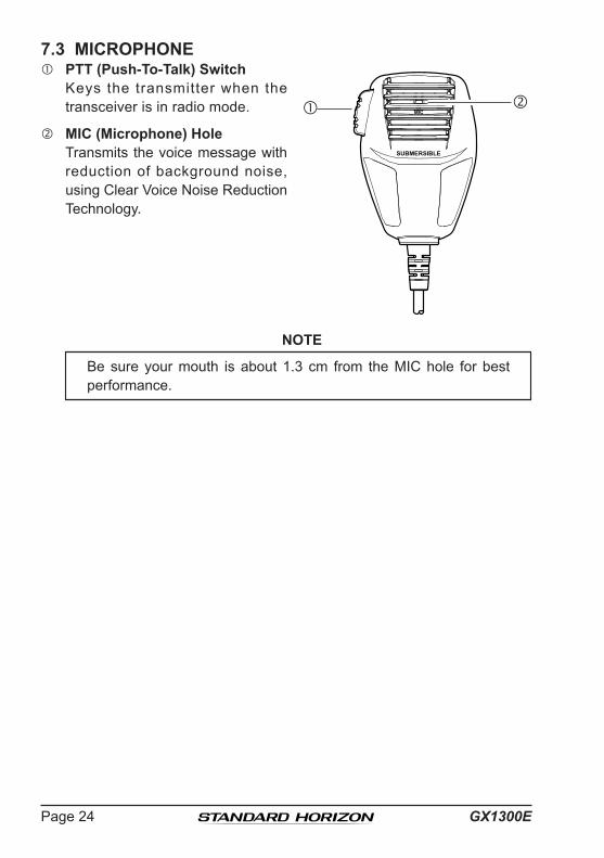
7.3 MICROPHONE PTT (Push-To-Talk) Switch Keys the transmitter when the
transceiver is in radio mode.
MIC (Microphone) Hole Transmits the voice message with
reduction of background noise, using Clear Voice Noise Reduction Technology.
NOTE
Be sure your mouth is about 1.3 cm from the MIC hole for best performance.

Page 25GX1300E
8 BASIC OPERATION8.1 RECEPTION1. After the GX1300E has been installed, ensure that the power supply and
antenna are properly connected.2. Turn the VOL knob clockwise until it clicks to turn the transceiver on.3. Turn the SQL knob fully counterclockwise. This state is known as “squelch
off”.4. Turn the VOL knob until noise or audio from the speaker is at a comfort-
able level.5. Turn the SQL knob clockwise until the random noise disappears. This
state is known as the “squelch threshold.”6. Press the ▲ or ▼ keys to select the desired channel. Refer to the
channel chart on page 102 for available channels.7. When a message is received, adjust the volume to the desired listen-
ing level with the VOL knob. The “BUSY” indicator appears on the LCD indicating that the channel is being used.
8.2 TRANSMISSION1. Perform steps 1 through 6 of RECEPTION.2. Before transmitting, monitor the channel to ensure it is clear.3 Press and hold the PTT (push-to-talk) switch of the microphone. The “TX”
indicator appears on the LCD.4. Speak slowly and clearly into the microphone.5. When the transmission is finished, release the PTT switch.
8.3 TRANSMIT TIME-OUT TIMER (TOT)When the PTT switch on the microphone is held down, transmit time is limit-ed to 5 minutes. This limits unintentional transmissions due to a stuck micro-phone. About 10 seconds before automatic transmitter shutdown, a warning beep will be heard from the speaker(s). The transceiver will automatically go to receive mode, even if the PTT switch is continually held down. Before transmitting again, the PTT switch must first be released and then pressed again.
NOTE
When a transmission was shut down by the TOT, the GX1300E can not transmit afterwards for 10 seconds.

GX1300EPage 26
8.4 SIMPLEX/DUPLEX CHANNEL USERefer to the VHF MARINE CHANNEL CHART (page 102) for instructions on use of simplex and duplex channels.
NOTE
8.5 USA, INTERNATIONAL, AND CANADA MODETo change the channel group from International to USA or Canada:
1. Press the MENU key to display the menu.
BACK SELECT
BACK SELECT
SETUPDSC SETUPCHANNEL SETUPATIS SETUPCONFIGURATION
BACK SELECT
CHANNEL SETUPCHANNEL GROUPMULTI WATCHSCAN MEMORYSCAN TYPE
BACK ENTER
CHANNEL GROUPUSAINTLCAN
2. Select “SETUP” with the ▲ / ▼ / ◄ / ► keys, then press the SELECT soft key.
3. Press the ▲ / ▼key to select “CHANNEL SETUP”, then press the SELECT soft key.
4. Press the ▲ / ▼ key to select “CHANNEL GROUP”, then press the SELECT soft key.
5. Press the ▲ / ▼ key to select desired channel group “USA”, “INTL”, or “CAN”.
6. Press the ENTER soft key to store the select-ed setting.
7. Press the BACK soft key to exit the menu.
All channels are factory-programmed in accordance with International, Industry Canada (Canada), and FCC (USA) regulations. Mode of op-eration cannot be altered from simplex to duplex or vice-versa.
uSa MoDe
BUSYMEMAC
USA25W
P16InternatIonaL MoDe
BUSYMEMAC
INTL25W
P16CanaDa MoDe
BUSYMEMAC
CAN25W
P16

Page 27GX1300E
8.6 SCANNINGAllows the user to select the scan type from Memory scan or Priority scan. “Memory scan” scans the channels that were programmed into memory. “Priority scan” scans the channels programmed in memory with the priority channel.
8.6.1 Selecting the Scan Type
1. Press the MENU key to display the menu.
BACK SELECT
BACK SELECT
SETUPDSC SETUPCHANNEL SETUPATIS SETUPCONFIGURATION
BACK SELECT
CHANNEL SETUPSCAN TYPESCAN RESUMEPRIORITY CHSUB CH
BACK ENTER
SCAN TYPEPRIORITY SCANMEMORY SCAN
2. Select “SETUP” with the ▲ / ▼ / ◄ / ► keys, then press the SELECT soft key.
3. Press the ▲ / ▼key to select “CHANNEL SETUP”, then press the SELECT soft key.
4. Select “SCAN TYPE” with the ▲ / ▼ keys, then press the SELECT soft key.
5. Press the ▲ / ▼ keys to select “PRIORITY SCAN” or “MEMORY SCAN.”
6. Press the ENTER soft key to store the selected setting.
7. Press the BACK soft key to exit the menu.
CH12
CH09CH01A
CH15
CH18CH22A
CH61A
CH68A
CH68A
CH88A
Priority Channel
CH12
CH09CH01A
CH15
CH18CH22A
CH61A
CH68A
CH68A
CH88A
MeMory SCan (M-SCan) PrIorIty SCan (P-SCan)

GX1300EPage 28
8.6.2 Scan Memory Programming
1. Press the MENU key to display the menu.
BACK SELECT
BACK SELECT
SETUPDSC SETUPCHANNEL SETUPATIS SETUPCONFIGURATION
BACK SELECT
CHANNEL SETUPCHANNEL GROUPMULTI WATCHSCAN MEMORYSCAN TYPE
BACK MEM
SCAN MEMORYCH: 16CH: 15CH: 14CH: 13
MEMMEM
MEM
2. Select “SETUP” with the ▲ / ▼ / ◄ / ► keys, then press the SELECT soft key.
3. Press the ▲ / ▼key to select “CHANNEL SETUP”, then press the SELECT soft key.
4. Press the ▲ / ▼ key to select “SCAN MEMORY”, then press the SELECT soft key.
5. Press the ▲ / ▼ key to select a desired channel to be scanned, then press the MEM soft key. “MEM” appears on the display, which indicates the channel has been selected to the scan channel.
6. Repeat step 5 for all the desired channels to be scanned.
7. To delete a channel from the list, select the channel then press the MEM soft key again. The “MEM” disappears from the display.
8. Press the BACK soft key to exit the menu.
NOTE
8.6.3 Memory Scanning (M-SCAN)
1. Adjust the SQL knob until background noise disappears.2. Select “MEMORY SCAN” as scan type via the SETUP menu.3. Press one of the soft keys, then press the SCAN
soft key (it may be necessary to press the ◄ / ► key to locate the SCAN soft key). “M-SCN” appears on the LCD. Scanning will proceed from the lowest to the highest programmed channel number and will stop on a channel when a transmission is received.
BUSYMEMAC
INTL25W
M-SCNP16
4. The channel number will blink during recep-tion.
5. To stop scanning, press the 16/S key or press one of the soft keys, then press the SCAN soft key.
Priority Channel can be set for each Channel Group.
Page 29GX1300E
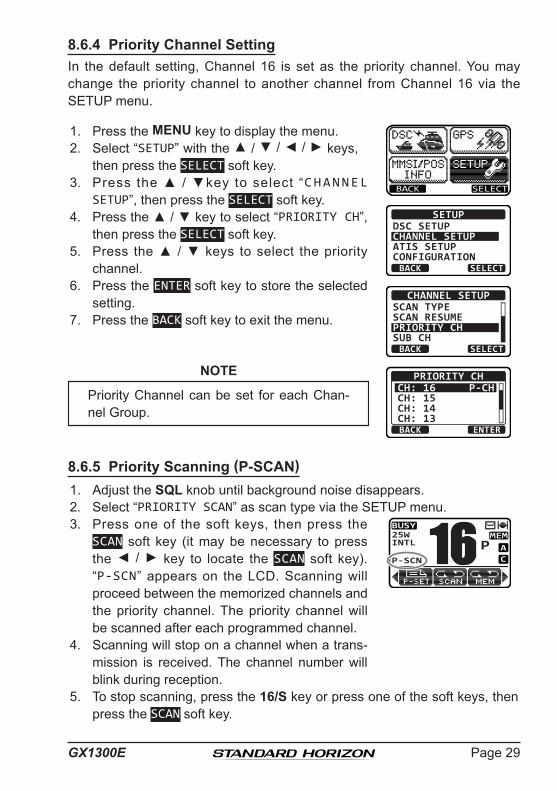
8.6.4 Priority Channel SettingIn the default setting, Channel 16 is set as the priority channel. You may change the priority channel to another channel from Channel 16 via the SETUP menu.
1. Press the MENU key to display the menu.
BACK SELECT
BACK SELECT
SETUPDSC SETUPCHANNEL SETUPATIS SETUPCONFIGURATION
BACK SELECT
CHANNEL SETUPSCAN TYPESCAN RESUMEPRIORITY CHSUB CH
BACK ENTER
PRIORITY CHCH: 16CH: 15CH: 14CH: 13
P-CH
2. Select “SETUP” with the ▲ / ▼ / ◄ / ► keys, then press the SELECT soft key.
3. Press the ▲ / ▼key to select “CHANNEL SETUP”, then press the SELECT soft key.
4. Press the ▲ / ▼ key to select “PRIORITY CH”, then press the SELECT soft key.
5. Press the ▲ / ▼ keys to select the priority channel.
6. Press the ENTER soft key to store the selected setting.
7. Press the BACK soft key to exit the menu.
NOTE
8.6.5 Priority Scanning (P-SCAN)1. Adjust the SQL knob until background noise disappears.2. Select “PRIORITY SCAN” as scan type via the SETUP menu.3. Press one of the soft keys, then press the
SCAN soft key (it may be necessary to press the ◄ / ► key to locate the SCAN soft key). “P-SCN” appears on the LCD. Scanning will proceed between the memorized channels and the priority channel. The priority channel will be scanned after each programmed channel.
BUSYMEMAC
INTL25W
P-SCNP16
4. Scanning will stop on a channel when a trans-mission is received. The channel number will blink during reception.
5. To stop scanning, press the 16/S key or press one of the soft keys, then press the SCAN soft key.
Priority Channel can be set for each Chan-nel Group.

GX1300EPage 30
8.7 MULTI WATCH (TO PRIORITY CHANNEL)Multi watch is used to scan two or three channels for communications.
In Dual Watch, a normal VHF channel and the priority channel are scanned alternately.
In Triple Watch, a normal VHF channel, the priority channel, and the sub channel are scanned alternately.
When a signal is received on the normal channel the radio briefly switches between the normal channel and the priority channel to look for a transmission. If the radio receives communications on the priority channel the radio stops and listens to the priority channel until communication ends and then starts dual or triple watch scan again.
8.7.1 Setting up the Multi Watch Operation
1. Press the MENU key to display the menu.
BACK SELECT
BACK SELECT
SETUPDSC SETUPCHANNEL SETUPATIS SETUPCONFIGURATION
BACK SELECT
CHANNEL SETUPCHANNEL GROUPMULTI WATCHSCAN MEMORYSCAN TYPE
BACK ENTER
MULTI WATCHDUAL
TRIPLE
2. Select “SETUP” with the ▲ / ▼ / ◄ / ► keys, then press the SELECT soft key.
3. Press the ▲ / ▼key to select “CHANNEL SETUP”, then press the SELECT soft key.
4. Select “MULTI WATCH” with the ▲ / ▼ keys, then press the SELECT soft key.
5. Press the ▲ / ▼ keys to select “DUAL ” or “TRIPLE.”
6. Press the ENTER soft key to store the selected setting.
7. Press the BACK soft key to exit the menu.

Page 31GX1300E
8.7.2 Starting the Dual Watch1. Adjust the SQL knob until the background noise disappears.2. Select the channel you wish to dual watch to the priority channel.3. Press one of the soft keys, then press the DW
soft key (it may be necessary to press the ◄ / ► key to locate the DW soft key).
“DW-## ” (## indicates the priority channel number you have selected) appears on the LCD. The radio will scan between the priority channel and the channel that was selected in step 2.
If a transmission is received on the channel selected in step 2, the GX1300E will dual watch to the priority channel.
BUSYMEMAC
P-SETINTL25W
DW-1688
4. To stop dual watch, press one of the soft keys, then press the DW soft key again.
When selecting “TRIPLE” in the SETUP menu, TW will be displayed as the soft key instead of DW.
NOTE
The priority channel may be changed from CH16 to another channel. Refer to section “8.6.4 Priority Channel Setting”.
GX1300EPage 32
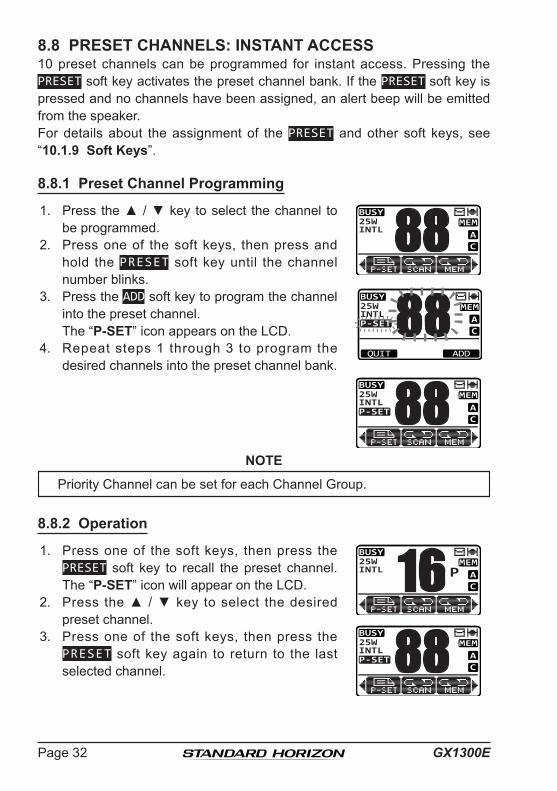
8.8 PRESET CHANNELS: INSTANT ACCESS10 preset channels can be programmed for instant access. Pressing the PRESET soft key activates the preset channel bank. If the PRESET soft key is pressed and no channels have been assigned, an alert beep will be emitted from the speaker.For details about the assignment of the PRESET and other soft keys, see “10.1.9 Soft Keys”.
8.8.1 Preset Channel Programming
1. Press the ▲ / ▼ key to select the channel to be programmed.
BUSYMEMAC
INTL25W 88BUSY
MEMAC
P-SETINTL25W 88QUIT ADD
BUSYMEMAC
P-SETINTL25W 88
2. Press one of the soft keys, then press and hold the PRESET soft key until the channel number blinks.
3. Press the ADD soft key to program the channel into the preset channel.
The “P-SET” icon appears on the LCD. 4. Repeat steps 1 through 3 to program the
desired channels into the preset channel bank.
NOTE
8.8.2 Operation
1. Press one of the soft keys, then press the PRESET soft key to recall the preset channel. The “P-SET” icon will appear on the LCD.
BUSYMEMAC
INTL25W
P16BUSY
MEMAC
P-SETINTL25W 88
2. Press the ▲ / ▼ key to select the desired preset channel.
3. Press one of the soft keys, then press the PRESET soft key again to return to the last selected channel.
Priority Channel can be set for each Channel Group.

Page 33GX1300E
8.8.3 Deleting a Preset Channel
1. Press one of the soft keys, then press the PRESET soft key.
BUSYMEMAC
P-SETINTL25W 88BUSY
MEMAC
P-SETINTL25W 88QUIT DELETE
BUSYMEMAC
INTL25W 88
2. Press the ▲ / ▼ key to select the preset channel to be deleted.
3. Press one of the soft keys, then press and hold the PRESET soft key until the channel number blinks.
4. Press the DELETE soft key to delete the channel from the preset channel bank.
The “P-SET” icon disappears on the LCD. 5. Repeat steps 2 through 4 to delete the desired
channels from the preset channel bank.
GX1300EPage 34
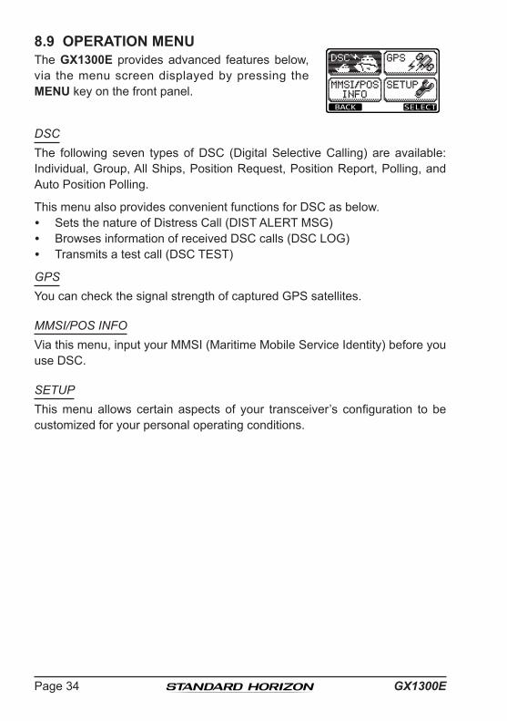
8.9 OPERATION MENUThe GX1300E provides advanced features below, via the menu screen displayed by pressing the MENU key on the front panel.
BACK SELECT
DSCThe following seven types of DSC (Digital Selective Calling) are available: Individual, Group, All Ships, Position Request, Position Report, Polling, and Auto Position Polling.
This menu also provides convenient functions for DSC as below. Sets the nature of Distress Call (DIST ALERT MSG) Browses information of received DSC calls (DSC LOG) Transmits a test call (DSC TEST)
GPSYou can check the signal strength of captured GPS satellites.
MMSI/POS INFOVia this menu, input your MMSI (Maritime Mobile Service Identity) before you use DSC.
SETUPThis menu allows certain aspects of your transceiver’s configuration to be customized for your personal operating conditions.

Page 35GX1300E
9 DIGITAL SELECTIVE CALLING9.1 GENERAL
WARNING
Digital Selective Calling (DSC) is a semi-automated method of establishing a radio call. It has been designated by the International Maritime Organization (IMO) as an international standard for establishing VHF, MF, and HF radio calls. It has also been designated as part of the Global Maritime Distress and Safety System (GMDSS). It is planned that DSC will eventually replace aural watches on distress frequencies and will be used to announce routine and urgent maritime safety information broadcasts.
This system allows mariners to instantly send a distress call with GPS position (when connected to the transceiver) to the Coast Guard and other vessels within range of the transmission. DSC will also allow mariners to initi-ate or receive Distress, Urgency, Safety, Routine, Position Request, Position Send, and Group calls to or from another vessel equipped with a DSC trans-ceiver.
9.2 MARITIME MOBILE SERVICE IDENTITY (MMSI)9.2.1 What is an MMSI?An MMSI is a nine digit number used on Marine radios capable of using Digital Selective Calling (DSC). This number is used like a telephone number to selectively call other vessels.
THIS NUMBER MUST BE PROGRAMMED INTO THE RADIO TO OPERATE DSC FUNCTIONS.How can I obtain an MMSI assignment?Please contact the Radio Licensing Authority for your country for information on how to obtain an MMSI number.
The GX1300E is designed to generate digital maritime distress and safety calls to facilitate search and rescue. To be effective as a safety device, this equipment must be used only within communication range of a shore-based VHF marine channel 70 distress and safety watch system. The range of signal may vary, however under normal condi-tions should be approximately 20 nautical miles.

GX1300EPage 36
9.2.2 Programming the MMSIWARNING
1. Press the MENU key to display the menu.
BACK SELECT
MMSI INPUT 1st: ---------
BACK FINISH SELECT
MMSI INPUT 1st: 366901234
BACK SELECTFINISH
MMSI INPUT 1st: *********
366901234 2nd:
BACK SELECTFINISH
MMSI INPUT
STORED MMSI
366901234
OK
2. Press the ▲ / ▼ key to select “MMSI/POS INFO”.
3. Press the SELECT soft key. (To cancel, press the BACK soft key.)
4. Press the ▲ / ▼ key to select the first number of your MMSI, then press the SELECT soft key to step to the next number.
5. Repeat step 4 to set your MMSI number (nine digits).
6. If a mistake was made entering in the MMSI number, press the ◄ / ► key until the wrong number is highlighted, then press the ▲ / ▼ key to correct the entry and press the SELECT soft key.
7. When f in ished programming the MMSI number, press the FINISH soft key. The radio will ask you to input the MMSI number again. Use steps 4 through 6 above.
8. After the second number has been input, press the FINISH soft key to store the MMSI.
9. Press the OK soft key to return to the “MMSI/POS INFO” screen.
10. Press the 16/S key or press the BACK soft key to return to radio opera-tion mode.
The MMSI can be input only once. Therefore, please be careful not to input the incorrect MMSI number. If you need to change the MMSI number after it has been entered, the radio will have to be re-turned to Factory Service. Refer to the section “11.2 FACTORY SER-VICE.”

Page 37GX1300E
9.3 DSC DISTRESS ALERTThe GX1300E is capable of transmitting and receiving DSC distress messag-es to all DSC radios. The GX1300E may be connected to a GPS to also transmit the latitude and longitude of the vessel.
NOTE
9.3.1 Transmitting a DSC Distress AlertNOTE
In order for your vessel's location to be transmitted, either connect a GPS to the GX1300E (refer to section “6.4 ACCESSORY CABLE”) or manually input your position (refer to section “9.9 MANUAL INPUT OF THE GPS LOCATION”).
Basic Operation
1. Lift the red spring loaded DISTRESS cover, then press and hold the DISTRESS key. The “DISTRESS” screen will appear on the LCD and the radios display will count down (3sec 2sec 1sec) and then the distress alert will be transmitted. The backlight of the LCD and keypad flashes while the radios display is counting down.
QUIT
!!DISTRESS!!UNDESIGNATED
[DISTRESS]Hold for 3 sec.
!!DISTRESS!!UNDESIGNATED
[ Transmitting ]
!!DISTRESS!!UNDESIGNATED
[Waiting for ACK]TX IN: 02:25
PAUSE INFOCANCEL
2. The GX1300E watches for an acknowledg-ment call on channel 70 or a voice call on channel 16 from another vessel.
3. If an vessel responds to you on channel 16, pick up the microphone and press and hold the PTT switch to advise your distress situation.
If a GPS with NMEA output is not connected to the radio, the GX1300E will beep 10 minutes after the radio is turned on and will continue to beep every 4 hours alerting to connect a GPS.
To be able to transmit a DSC distress alert, a MMSI number must be programmed (refer to section “9.2.2 Programming the MMSI”).
GX1300EPage 38
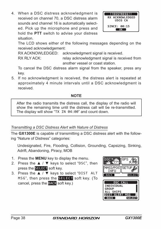
4. When a DSC distress acknowledgment is received on channel 70, a DSC distress alarm sounds and channel 16 is automatically select-ed. Pick up the microphone and press and hold the PTT switch to advise your distress situation.
!!DISTRESS!!RX ACKNOWLEDGED USCG CA
SINCE: 00:15OK
The LCD shows either of the following messages depending on the received acknowledgement:RX ACKNOWLEDGED: acknowledgment signal is received.RX RLY ACK: relay acknowledgment signal is received from
another vessel or coast station. To cancel the DSC distress alarm signal from the speaker, press any
key.5. If no acknowledgment is received, the distress alert is repeated at
approximately 4 minute intervals until a DSC acknowledgment is received.
NOTE
Transmitting a DSC Distress Alert with Nature of DistressThe GX1300E is capable of transmitting a DSC distress alert with the follow-ing “Nature of Distress” categories:
Undesignated, Fire, Flooding, Collision, Grounding, Capsizing, Sinking, Adrift, Abandoning, Piracy, MOB
1. Press the MENU key to display the menu.
BACK SELECT
BACK SELECT
DSC CALLINDIVIDUALGROUPALL SHIPSDIST ALERT MSG
2. Press the ▲ / ▼ keys to select “DSC”, then press the SELECT soft key.
3. Press the ▲ / ▼ keys to select “DIST ALT MSG”, then press the SELECT soft key. (To cancel, press the BACK soft key.)
After the radio transmits the distress call, the display of the radio will show the remaining time until the distress call will be re-transmitted. The display will show “TX IN 04:00” and count down.
Page 39GX1300E
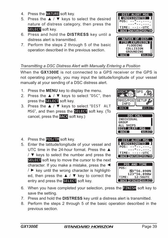
4. Press the NATURE soft key.
BACK POS/TM
DIST ALERT MSGUNDESIGNATED
POS: --°--.---- ---°--.----TIME: --:--UTC
NATURE
BACK SELECT
NATUER OF DISTFIRE,EXPLOSION
FLOODINGCOLLISIONGROUNDING
5. Press the ▲ / ▼ keys to select the desired nature of distress category, then press the SELECT soft key.
6. Press and hold the DISTRESS key until a distress alert is transmitted.
7. Perform the steps 2 through 5 of the basic operation described in the previous section.
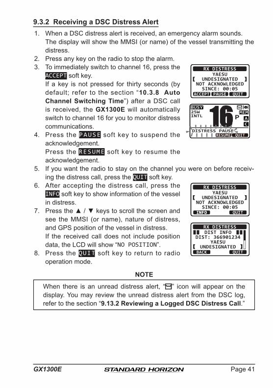
Transmitting a DSC Distress Alert with Manually Entering a PositionWhen the GX1300E is not connected to a GPS receiver or the GPS is not operating properly, you may input the latitude/longitude of your vessel manually at your sending of a DSC distress alert.
1. Press the MENU key to display the menu.
BACK SELECT
BACK SELECT
DSC CALLINDIVIDUALGROUPALL SHIPSDIST ALERT MSG
2. Press the ▲ / ▼ keys to select “DSC”, then press the SELECT soft key.
3. Press the ▲ / ▼ keys to select “DIST ALT MSG”, and then press the SELECT soft key. (To cancel, press the BACK soft key.)
4. Press the POS/TM soft key.
BACK POS/TM
DIST ALERT MSGUNDESIGNATED
POS: --°--.---- ---°--.----TIME: --:--UTC
NATURE
POS AND TIME
23°56.890N123°56.890W
POS:
TIME: 12:56UTCBACK SELECTFINISH
5. Enter the latitude/longitude of your vessel and UTC time in the 24-hour format. Press the ▲ / ▼ keys to select the number and press the SELECT soft key to move the cursor to the next character. If you make a mistake, press the ◄ / ► key until the wrong character is highlight-ed, then press the ▲ / ▼ key to correct the entry and press the SELECT soft key.
6. When you have completed your selection, press the FINISH soft key to save the setting.
7. Press and hold the DISTRESS key until a distress alert is transmitted.8. Perform the steps 2 through 5 of the basic operation described in the
previous section.

GX1300EPage 40
Pausing a DSC Distress AlertAfter a DSC distress call is transmitted, it is repeated every 4 minutes until the call is canceled by the user or until the radio is turned off and on again. The GX1300E has provision to suspend (pause) the re-transmitting of the distress call by the procedure below.
1. After the distress call is transmitted, the radio will show the display as on the right.
Looking at this display you will notice “TX in 02:25”, this is the time when the radio will re-transmit the distress call.
!!DISTRESS!!UNDESIGNATED
[Waiting for ACK]TX IN: 02:25
PAUSE INFOCANCEL
!!DISTRESS!!UNDESIGNATED
Retransmissionis now pausing!TX IN: 02:25
RESUME INFOCANCEL
2. To suspend re-transmitting the distress call, press the PAUSE soft key.
3. To resume counting down to transmit the distress call, press the RESUME soft key.
Canceling a DSC Distress Alert
T h e G X 1 3 0 0 E h a s t h e capabi l i ty to t ransmi t a DSC distress cancel call by pressing the CANCEL soft key, then press the YES soft key.
!!DISTRESS!!UNDESIGNATED
[Waiting for ACK]TX IN: 02:25
PAUSE INFOCANCEL
!!DISTRESS!!UNDESIGNATED
Do you want tocancel a DIST?YES NO
Page 41GX1300E
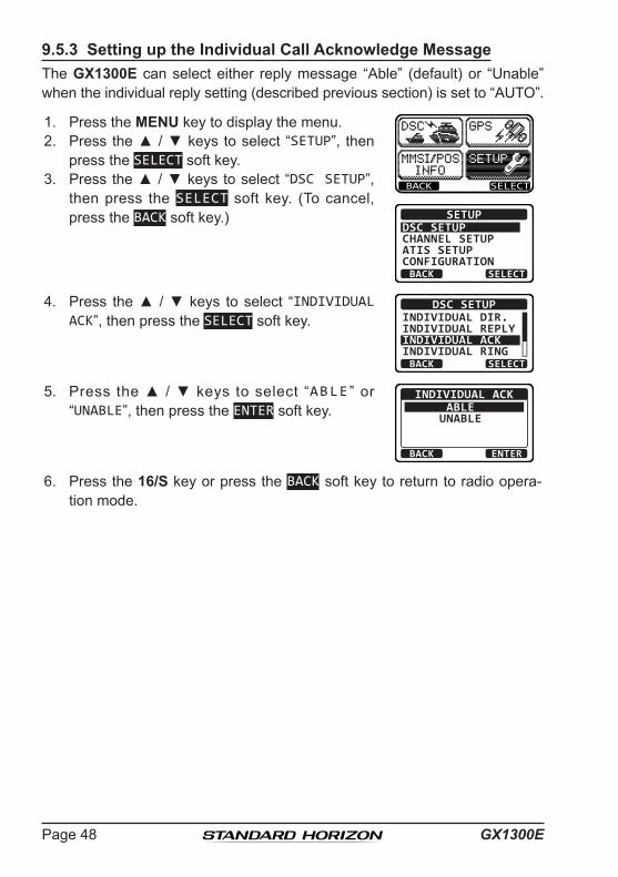
9.3.2 Receiving a DSC Distress Alert1. When a DSC distress alert is received, an emergency alarm sounds. The display will show the MMSI (or name) of the vessel transmitting the
distress.2. Press any key on the radio to stop the alarm.3. To immediately switch to channel 16, press the
ACCEPT soft key. If a key is not pressed for thirty seconds (by
default; refer to the section “10.3.8 Auto Channel Switching Time”) after a DSC call is received, the GX1300E will automatically switch to channel 16 for you to monitor distress communications.
RX DISTRESSYAESU
UNDESIGNATEDNOT ACKNOWLEDGED
SINCE: 00:05ACCEPT QUITPAUSE
BUSYMEMAC
INTL25W
DISTRESS PAUSE
P16QUITRESUME4. Press the PAUSE soft key to suspend the
acknowledgement. Press the RESUME soft key to resume the
acknowledgement.5. If you want the radio to stay on the channel you were on before receiv-
ing the distress call, press the QUIT soft key.6. After accepting the distress call, press the
INFO soft key to show information of the vessel in distress.
RX DISTRESSYAESU
UNDESIGNATEDNOT ACKNOWLEDGED
SINCE: 00:05INFO QUITINFO
DIST INFODIST: 366901234
YAESUUNDESIGNATED
RX DISTRESS
BACK QUIT
7. Press the ▲ / ▼ keys to scroll the screen and see the MMSI (or name), nature of distress, and GPS position of the vessel in distress.
If the received call does not include position data, the LCD will show “NO POSITION”.
8. Press the QUIT soft key to return to radio operation mode.
NOTE
When there is an unread distress alert, “ ” icon will appear on the display. You may review the unread distress alert from the DSC log, refer to the section “9.13.2 Reviewing a Logged DSC Distress Call.”

GX1300EPage 42
9.4 ALL SHIPS CALLThe all ships call function allows contact to be established with DSC equipped vessels without having their MMSI in the individual calling direc-tory. Also, priority for the call can be designated as "urgency" or "safety".
URGENCY Call: This type of call is used when a vessel may not truly be in distress, but has a potential problem that may lead to a distress situation. This call is the same as saying “PAN PAN, PAN PAN, PAN PAN” on channel 16.
SAFETY Call: This type of call is used to transmit boating safety informa-tion to other vessels. This message usually contains infor-mation about an overdue boat, debris in the water, loss of a navigation aid or an important meteorological message. This call is the same as saying “Securite, Securite, Securite.”
9.4.1 Transmitting an All Ships Call1. Press the MENU key to display the menu.
BACK SELECT
BACK SELECT
DSC CALLINDIVIDUALGROUPALL SHIPSDIST ALERT MSG
2. Press the ▲ / ▼ keys to select “DSC”, then press the SELECT soft key.
3. Press the ▲ / ▼ keys to select “ALL SHIPS”, and then press the SELECT soft key. (To cancel, press the BACK soft key.)
4. Press the ▲ / ▼ keys to select the category of the call (“SAFETY” or “URGENCY”), then press the SELECT soft key.
BACK SELECT
CATEGORYSAFETYURGENCY
5. Press the ▲ / ▼ keys to select the operating channel you want to communicate on, then press the SELECT soft key.
Press the MANUAL soft key to select channels other than the Intership channel.
BACK SELECT
INTERSHIP CHCH:16CH:06CH:08CH:09MANUAL
To select “INTERSHIP CH” again, press the INTSHP soft key.6. Press the YES soft key to transmit the selected
type of all ships call.
YES NO
ALL SHIPS
CATEG: SAFETYCH: 16
Transmit a Call?

Page 43GX1300E
7. After the all ships call is transmitted, the trans-ceiver will switch to the channel which select-ed on the step 5 above, with no change of the display. To change the display, press the QUIT soft key.
ALL SHIPS
CATEG: SAFETY SINCE: 00:05 [ Transmitted ]
QUIT
8. Listen to the channel to make sure it is not busy, then key the micro-phone and say “PAN PAN, PAN PAN, PAN PAN” or “Securite, Securite, Securite” depending on the priority of the call. Say your call sign and announce the channel you wish to switch to for communications.
9.4.2 Receiving an All Ships Call1. When an all ships call is received, an emergency alarm sounds. The display will show the MMSI (or name) of the vessel transmitting the
all ships call.2. Press any key on the radio to stop the alarm.3. To immediately switch to requested channel,
press the ACCEPT soft key. If a key is not pressed for thirty seconds (by
default; refer to the section “10.3.8 Auto Channel Switching Time”) after an all ships call is received, the GX1300E will automati-cally switch to the requested channel for you to monitor communications.
RX ALL SHIPS YAESUCATEG: SAFETY CH: 08SINCE: 00:05
ACCEPT QUITPAUSE
BUSYMEMAC
INTL25W 08ALL SHIPS PAUSE
QUITRESUME4. Press the PAUSE soft key to suspend the acknowledgement.
Press the RESUME soft key to resume the acknowledgement.
5. If you want the radio to stay on the channel you were on before receiv-ing the all ships call, press the QUIT soft key.
6. Press the ▲ / ▼ keys to scroll the screen and see the MMSI (or name) of the calling vessel, category of the call and requested operating channel.
RX ALL SHIPS YAESUCATEG: SAFETY CH: 08SINCE: 00:08ABLE QUITUNABLE
7. Press the QUIT soft key to display the operat-ing channel number of the requested channel.
8. Press the PTT switch on the microphone and talk to the calling vessel.

GX1300EPage 44
9.4.3 Setting up the All Ships Call RingerThe GX1300E has the capability to turn off the all ships call ringer.1. Press the MENU key to display the menu.
BACK SELECT
BACK SELECT
SETUPDSC SETUPGROUPCHANNEL SETUPATIS SETUPCONFIGURATION
2. Press the ▲ / ▼ keys to select “SETUP”, then press the SELECT soft key.
3. Press the ▲ / ▼ keys to select “DSC SETUP”, then press the SELECT soft key. (To cancel, press the BACK soft key.)
4. Select “DSC BEEP” with the ▲ / ▼ keys, then press the SELECT soft key.
BACK SELECT
DSC SETUPAUTO POS POLLAUTO POS TIMECH SWITCH TIMERDSC BEEP
5. Select “ALL SHIPS” with the ▲ / ▼ keys, then press the SELECT soft key.
BACK SELECT
DSC BEEPINDIVIDUALGROUPALL SHIPSPOS REQUEST
ONONON
OFF
6. Press the ▲ / ▼ keys to select “OFF”, then press the ENTER soft key.
BACK ENTER
ALL SHIPSOFFON
7. Press the 16/S key or press the BACK soft key to return to radio opera-tion mode.
If you wish to return to enabling the ringer tone, just repeat the above proce-dure, pressing the ▲ / ▼ keys to select “ON” in step 6 above.

Page 45GX1300E
9.5 INDIVIDUAL CALLThis feature allows the GX1300E to contact another vessel with a DSC VHF radio and automatically switch the receiving radio to a desired communica-tions channel. This feature is similar to calling a vessel on CH16 and request-ing to go to another channel (switching to the channel is private between the two stations).
9.5.1 Setting up the Individual / Position Call DirectoryThe GX1300E has a DSC directory that allows you to store a vessel or person’s name and the MMSI (Maritime Mobile Service Identity Number) number associated with vessels you wish to transmit individual calls, position requests and position report transmissions. The GX1300E can store up to 60 individual MMSI numbers with vessel's or person's names.
To transmit an Individual call you must program this directory with the infor-mation of the persons you wish to call, similar to a cellular phones directory.
1. Press the MENU key to display the menu.
BACK SELECT
BACK SELECT
SETUPDSC SETUPGROUPCHANNEL SETUPATIS SETUPCONFIGURATION
2. Press the ▲ / ▼ keys to select “SETUP”, then press the SELECT soft key.
3. Press the ▲ / ▼ keys to select “DSC SETUP”, then press the SELECT soft key. (To cancel, press the BACK soft key.)
4. Select “INDIVIDUAL DIR.” with the ▲ / ▼ keys, then press the SELECT soft key.
BACK SELECT
DSC SETUPINDIVIDUAL DIR.INDIVIDUAL REPLYINDIVIDUAL ACKINDIVIDUAL RING
5. Select “ADD” with the ▲ / ▼ keys, then press the SELECT soft key.
BACK SELECT
INDIVIDUAL DIR.ADDEDIT
DELETE
6. Select “NAME” with the ▲ / ▼ keys, then press the SELECT soft key.
BACK SELECT
ADDNAME: ------------MMSI: ---------

GX1300EPage 46
7. Press the ▲ / ▼ keys to scroll to the first letter of the name of the vessel or person you want to list in the directory.
BACK SELECTFINISH
ADDNAME: Y-----------
8. Press the SELECT soft key to store the first letter of the name and step to the next letter to the right.
9. Repeat steps 7 and 8 until the name is complete. Press the ► key to move to the next space if you want to enter a blank
space in the name. If a mistake was made entering in the name, press the ◄ / ► keys
repeatedly until the wrong letter is highlighted, then press the ▲ / ▼ keys to correct the entry.
10. After the twelfth letter or space has been entered, press the FINISH soft key to return to the previous screen.
ADDNAME: YAESU-------MMSI: ---------BACK SELECTFINISH
BACK SELECTFINISH
ADDMMSI: 3--------
11. Select “MMSI” with the ▲ / ▼ keys, then press the SELECT soft key.
12. Press the ▲ / ▼ keys to scroll through numbers, 0 to 9.
13. Press the SELECT soft key to store the number and step to the next digit to the right.
14. Repeat steps 12 and 13 until the MMSI is complete. If a mistake was made entering in the MMSI number, press the ◄ / ►
keys repeatedly until the wrong number is highlighted, then press the ▲ / ▼ keys to correct the entry.
15. After the ninth number has been entered, press the FINISH soft key to return to the previous screen.
ADDNAME: YAESU-------MMSI: 366901555BACK SELECTFINISH16. Press the FINISH soft key to save the entered
address.17. To enter another individual address, repeat steps 5 through 16.18. Press the 16/S key or press the BACK soft key to return to radio opera-
tion mode.

Page 47GX1300E
9.5.2 Setting up Individual Call ReplyAllows setting up the radio to automatically or manually (default setting) respond to a DSC individual call requesting you to switch to a working channel for voice communications. When the manual response is selected the MMSI of the calling vessel is shown allowing you to see who is calling. This function is similar to caller ID on a cellular phone.
1. Press the MENU key to display the menu.
BACK SELECT
BACK SELECT
SETUPDSC SETUPGROUPCHANNEL SETUPATIS SETUPCONFIGURATION
2. Press the ▲ / ▼ keys to select “SETUP”, then press the SELECT soft key.
3. Press the ▲ / ▼ keys to select “DSC SETUP”, then press the SELECT soft key. (To cancel, press the BACK soft key.)
4. Press the ▲ / ▼ keys to select “INDIVIDUAL REPLY”, then press the SELECT soft key.
BACK SELECT
DSC SETUPINDIVIDUAL DIR.INDIVIDUAL REPLYINDIVIDUAL ACKINDIVIDUAL RING
5. Press the ▲ / ▼ keys to select “AUTO ” or “MANUAL”, then press the ENTER soft key.
BACK ENTER
INDIVIDUAL REPLYAUTO
MANUAL
6. Press the 16/S key or press the BACK soft key to return to radio opera-tion mode.
GX1300EPage 48
9.5.3 Setting up the Individual Call Acknowledge MessageThe GX1300E can select either reply message “Able” (default) or “Unable” when the individual reply setting (described previous section) is set to “AUTO”.
1. Press the MENU key to display the menu.
BACK SELECT
BACK SELECT
SETUPDSC SETUPGROUPCHANNEL SETUPATIS SETUPCONFIGURATION
2. Press the ▲ / ▼ keys to select “SETUP”, then press the SELECT soft key.
3. Press the ▲ / ▼ keys to select “DSC SETUP”, then press the SELECT soft key. (To cancel, press the BACK soft key.)
4. Press the ▲ / ▼ keys to select “INDIVIDUAL ACK”, then press the SELECT soft key.
BACK SELECT
DSC SETUPINDIVIDUAL DIR.INDIVIDUAL REPLYINDIVIDUAL ACKINDIVIDUAL RING
5. Press the ▲ / ▼ keys to select “ABLE ” or “UNABLE”, then press the ENTER soft key.
BACK ENTER
INDIVIDUAL ACKABLE
UNABLE
6. Press the 16/S key or press the BACK soft key to return to radio opera-tion mode.
Page 49GX1300E
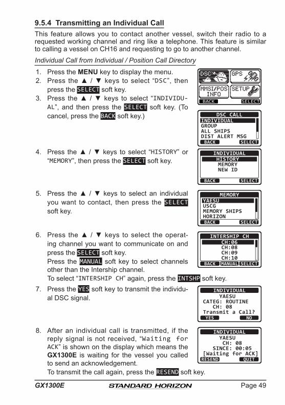
9.5.4 Transmitting an Individual CallThis feature allows you to contact another vessel, switch their radio to a requested working channel and ring like a telephone. This feature is similar to calling a vessel on CH16 and requesting to go to another channel.
Individual Call from Individual / Position Call Directory
1. Press the MENU key to display the menu.
BACK SELECT
BACK SELECT
DSC CALLINDIVIDUALGROUPALL SHIPSDIST ALERT MSG
2. Press the ▲ / ▼ keys to select “DSC”, then press the SELECT soft key.
3. Press the ▲ / ▼ keys to select “INDIVIDU-AL”, and then press the SELECT soft key. (To cancel, press the BACK soft key.)
4. Press the ▲ / ▼ keys to select “HISTORY” or “MEMORY”, then press the SELECT soft key.
BACK SELECT
INDIVIDUALHISTORYMEMORYNEW ID
5. Press the ▲ / ▼ keys to select an individual you want to contact, then press the SELECT soft key.
BACK SELECT
MEMORYYAESUUSCGMEMORY SHIPSHORIZON
6. Press the ▲ / ▼ keys to select the operat-ing channel you want to communicate on and press the SELECT soft key.
Press the MANUAL soft key to select channels other than the Intership channel.
BACK SELECT
INTERSHIP CHCH:06CH:08CH:09CH:10MANUAL
To select “INTERSHIP CH” again, press the INTSHP soft key.7. Press the YES soft key to transmit the individu-
al DSC signal.INDIVIDUAL
YAESUCATEG: ROUTINE CH: 08Transmit a Call?YES NO
8. After an individual call is transmitted, if the reply signal is not received, “Waiting for ACK” is shown on the display which means the GX1300E is waiting for the vessel you called to send an acknowledgement.
INDIVIDUAL YAESU CH: 08 SINCE: 00:05[Waiting for ACK]RESEND QUIT
To transmit the call again, press the RESEND soft key.
GX1300EPage 50
9. When the GX1300E receives an acknowledgement from the vessel you called, the radio will automatically switch to the operating channel selected in step 6 and produce a ringing sound.
10. Key the microphone and call the other vessel you desire to communi-cate with.
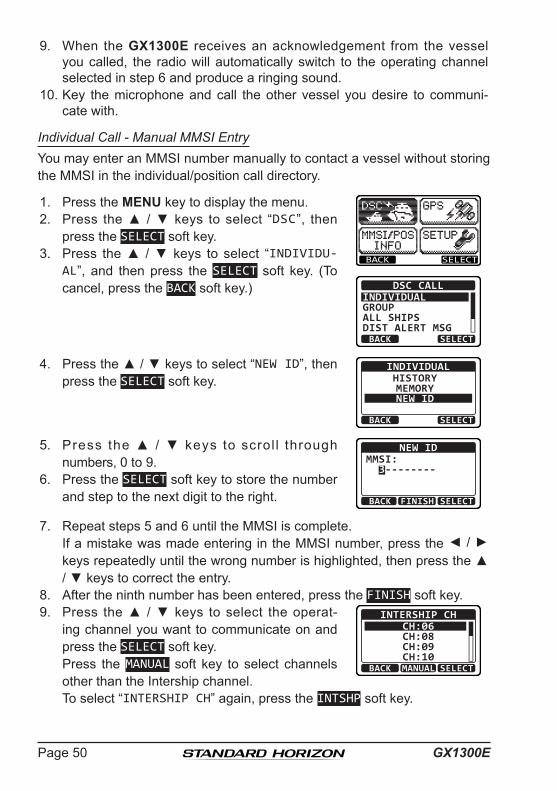
Individual Call - Manual MMSI EntryYou may enter an MMSI number manually to contact a vessel without storing the MMSI in the individual/position call directory.
1. Press the MENU key to display the menu.
BACK SELECT
BACK SELECT
DSC CALLINDIVIDUALGROUPALL SHIPSDIST ALERT MSG
2. Press the ▲ / ▼ keys to select “DSC”, then press the SELECT soft key.
3. Press the ▲ / ▼ keys to select “INDIVIDU-AL”, and then press the SELECT soft key. (To cancel, press the BACK soft key.)
4. Press the ▲ / ▼ keys to select “NEW ID”, then press the SELECT soft key.
BACK SELECT
INDIVIDUALHISTORYMEMORYNEW ID
5. Press the ▲ / ▼ keys to scrol l through numbers, 0 to 9.
BACK SELECTFINISH
NEW IDMMSI: 3--------
6. Press the SELECT soft key to store the number and step to the next digit to the right.
7. Repeat steps 5 and 6 until the MMSI is complete. If a mistake was made entering in the MMSI number, press the ◄ / ►
keys repeatedly until the wrong number is highlighted, then press the ▲ / ▼ keys to correct the entry.
8. After the ninth number has been entered, press the FINISH soft key.9. Press the ▲ / ▼ keys to select the operat-
ing channel you want to communicate on and press the SELECT soft key.
Press the MANUAL soft key to select channels other than the Intership channel.
BACK SELECT
INTERSHIP CHCH:06CH:08CH:09CH:10MANUAL
To select “INTERSHIP CH” again, press the INTSHP soft key.
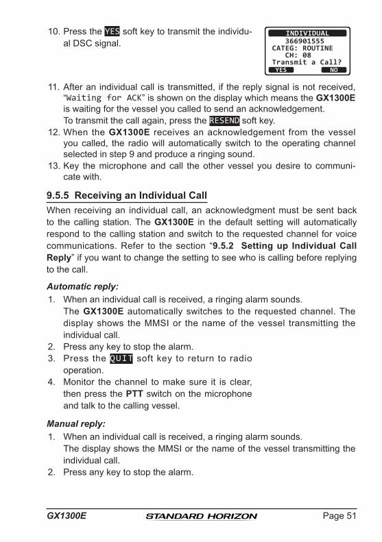
Page 51GX1300E
10. Press the YES soft key to transmit the individu-al DSC signal.
INDIVIDUAL 366901555CATEG: ROUTINE CH: 08Transmit a Call?YES NO
11. After an individual call is transmitted, if the reply signal is not received, “Waiting for ACK” is shown on the display which means the GX1300E is waiting for the vessel you called to send an acknowledgement.
To transmit the call again, press the RESEND soft key.12. When the GX1300E receives an acknowledgement from the vessel
you called, the radio will automatically switch to the operating channel selected in step 9 and produce a ringing sound.
13. Key the microphone and call the other vessel you desire to communi-cate with.
9.5.5 Receiving an Individual CallWhen receiving an individual call, an acknowledgment must be sent back to the calling station. The GX1300E in the default setting will automatically respond to the calling station and switch to the requested channel for voice communications. Refer to the section “9.5.2 Setting up Individual Call Reply” if you want to change the setting to see who is calling before replying to the call.
Automatic reply:1. When an individual call is received, a ringing alarm sounds. The GX1300E automatically switches to the requested channel. The
display shows the MMSI or the name of the vessel transmitting the individual call.
2. Press any key to stop the alarm.3. Press the QUIT soft key to return to radio
operation.4. Monitor the channel to make sure it is clear,
then press the PTT switch on the microphone and talk to the calling vessel.
Manual reply:1. When an individual call is received, a ringing alarm sounds. The display shows the MMSI or the name of the vessel transmitting the
individual call.2. Press any key to stop the alarm.

GX1300EPage 52
3. Press the ACCEPT soft key to accept the call. RX INDIVIDUAL YAESUCATEG: ROUTINE CH: 08SINCE: 00:05
ACCEPT QUITPAUSE
4. Press the PAUSE soft key to suspend the acknowledgement.
Press the RESUME soft key to resume the acknowledgement.
BUSYMEMAC
USA25W
INDIVIDUAL PAUSE08
QUITRESUME
5. After accepting the call, press the ABLE soft key to switch to the requested channel. (To inform that you cannot respond, press the UNABLE soft key.)
RX INDIVIDUAL YAESUCATEG: ROUTINE CH: 08SINCE: 00:08ABLE QUITUNABLE
6. Press the YES soft key to send an acknowl-edgement.
Press the CHG CH soft key to change the channel for communication from the requested one.
RX INDIVIDUAL YAESU CH: 08ABLE TO COMPLYTransmit a Call?YES NOCNG CH
RX INDIVIDUAL YAESUCH: 08
SINCE: 00:05[ Connected ]
RESEND QUIT
7. After sending the acknowledgement, the GX1300E switches to the requested channel or to the channel selected in step 6, without changing the display. To change the display, press the QUIT soft key.
8. Monitor the channel to make sure it is clear, then press the PTT switch on the microphone and talk to the calling vessel.

Page 53GX1300E
9.5.6 Setting up the Individual Call RingerWhen an individual call is received the radio will produce a ringing tone for 2 minutes (by default). This selection allows the individual call ringer time to be changed.
1. Press the MENU key to display the menu.
BACK SELECT
BACK SELECT
SETUPDSC SETUPGROUPCHANNEL SETUPATIS SETUPCONFIGURATION
2. Press the ▲ / ▼ keys to select “SETUP”, then press the SELECT soft key.
3. Press the ▲ / ▼ keys to select “DSC SETUP”, then press the SELECT soft key. (To cancel, press the BACK soft key.)
4. Select “INDIVIDUAL RING” with the ▲ / ▼ keys, then press the SELECT soft key.
BACK SELECT
DSC SETUPINDIVIDUAL DIR.INDIVIDUAL REPLYINDIVIDUAL ACKINDIVIDUAL RING
5. Press the ▲ / ▼ keys to select ringing time of an individual call, then press the ENTER soft key.
BACK ENTER
INDIVIDUAL RING 2 min 5 sec10 sec15 sec
6. Press the 16/S key or press the BACK soft key to return to radio opera-tion mode.

GX1300EPage 54
The GX1300E has the capability to turn off the individual call ringer.1. Press the MENU key to display the menu.
BACK SELECT
BACK SELECT
SETUPDSC SETUPGROUPCHANNEL SETUPATIS SETUPCONFIGURATION
2. Press the ▲ / ▼ keys to select “SETUP”, then press the SELECT soft key.
3. Press the ▲ / ▼ keys to select “DSC SETUP”, then press the SELECT soft key. (To cancel, press the BACK soft key.)
4. Select “DSC BEEP” with the ▲ / ▼ keys, then press the SELECT soft key.
BACK SELECT
DSC SETUPAUTO POS POLLAUTO POS TIMECH SWITCH TIMERDSC BEEP
5. Select “INDIVIDUAL” with the ▲ / ▼ keys, then press the SELECT soft key.
BACK SELECT
DSC BEEPINDIVIDUALGROUPALL SHIPSPOS REQUEST
ONONON
OFF
6. Press the ▲ / ▼ keys to select “OFF”, then press the ENTER soft key.
BACK ENTER
INDIVIDUALOFFON
7. Press the 16/S key or press the BACK soft key to return to radio opera-tion mode.
If you wish to return to enabling the ringer tone, just repeat the above proce-dure, pressing the ▲ / ▼ keys to select “ON” in step 6 above.

Page 55GX1300E
9.6 GROUP CALLThis feature allows the user to contact a group of specific vessels (example members of a yacht club) with a group MMSI number using the group call function to automatically switch to a desired channel for voice communi-cations. This function is very useful for yacht clubs and vessels traveling together that want to collectively make announcements on a predetermined channel. The GX1300E can store up to 20 group call entries.
9.6.1 Setting up a Group CallFor this function to operate the same group MMSI must be programmed into all the DSC VHF radios within the group of vessels that will be using this feature. To understand about group MMSI programming, first a Ship MMSI has to be understood.
Ship MMSI: The first three digits called a MID (Mobile Identity Group) of a ship MMSI denote the country the ship registered for a MMSI. The last 6 digits are specific to the ships ID. Ship MMSI Example: If your MMSI is “366123456”, “366” is MID which denote the country and “123456” is the ships ID for you.Group MMSI: Group MMSI numbers are not assigned by the FCC or other organiza-
tions licensed to assign ship MMSI numbers. The first digit of a group MMSI is always set to “0” by the international
rules. All Standard Horizon radios are preset so when programming a group MMSI the first digit is set to “0”.
The USCG recommends programming the MID of a ships MMSI into the second, third and fourth digits of the group MMSI as it denotes the area the ship is located in.
The last 5 digits are decided upon by persons in the group. This is an important step as all radios in the group must contain the same group MMSI so they can be contacted by each other. There is a chance that another group of vessels may program in the same group MMSI. If this happens, simply change one or more of the last 5 digits of the group MMSI.
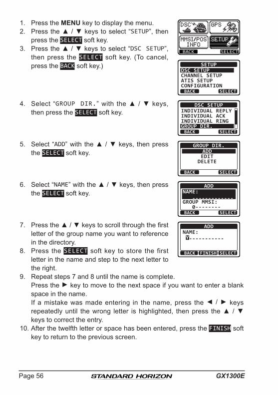
GX1300EPage 56
1. Press the MENU key to display the menu.
BACK SELECT
BACK SELECT
SETUPDSC SETUPGROUPCHANNEL SETUPATIS SETUPCONFIGURATION
2. Press the ▲ / ▼ keys to select “SETUP”, then press the SELECT soft key.
3. Press the ▲ / ▼ keys to select “DSC SETUP”, then press the SELECT soft key. (To cancel, press the BACK soft key.)
4. Select “GROUP DIR.” with the ▲ / ▼ keys, then press the SELECT soft key.
BACK SELECT
DSC SETUPINDIVIDUAL REPLYINDIVIDUAL ACKINDIVIDUAL RINGGROUP DIR.
5. Select “ADD” with the ▲ / ▼ keys, then press the SELECT soft key.
BACK SELECT
GROUP DIR.ADDEDIT
DELETE
6. Select “NAME” with the ▲ / ▼ keys, then press the SELECT soft key.
BACK SELECT
ADDNAME: -------------GROUP MMSI: 0--------
7. Press the ▲ / ▼ keys to scroll through the first letter of the group name you want to reference in the directory.
BACK SELECTFINISH
ADDNAME: Y-----------
8. Press the SELECT soft key to store the first letter in the name and step to the next letter to the right.
9. Repeat steps 7 and 8 until the name is complete. Press the ► key to move to the next space if you want to enter a blank
space in the name. If a mistake was made entering in the name, press the ◄ / ► keys
repeatedly until the wrong letter is highlighted, then press the ▲ / ▼ keys to correct the entry.
10. After the twelfth letter or space has been entered, press the FINISH soft key to return to the previous screen.
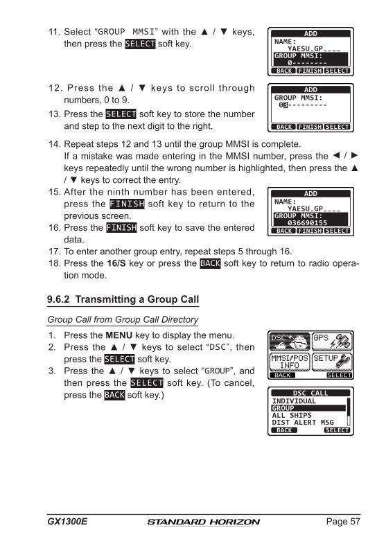
Page 57GX1300E
11. Select “GROUP MMSI” with the ▲ / ▼ keys, then press the SELECT soft key.
ADDNAME: YAESU-GP----GROUP MMSI: 0--------BACK SELECTFINISH
12. Press the ▲ / ▼ keys to scroll through numbers, 0 to 9.
BACK SELECTFINISH
ADDGROUP MMSI: 03---------
13. Press the SELECT soft key to store the number and step to the next digit to the right.
14. Repeat steps 12 and 13 until the group MMSI is complete. If a mistake was made entering in the MMSI number, press the ◄ / ►
keys repeatedly until the wrong number is highlighted, then press the ▲ / ▼ keys to correct the entry.
15. After the ninth number has been entered, press the FINISH soft key to return to the previous screen.
ADDNAME: YAESU-GP----GROUP MMSI: 036690155BACK SELECTFINISH16. Press the FINISH soft key to save the entered
data.17. To enter another group entry, repeat steps 5 through 16.18. Press the 16/S key or press the BACK soft key to return to radio opera-
tion mode.
9.6.2 Transmitting a Group Call
Group Call from Group Call Directory
1. Press the MENU key to display the menu.
BACK SELECT
BACK SELECT
DSC CALLINDIVIDUALGROUPALL SHIPSDIST ALERT MSG
2. Press the ▲ / ▼ keys to select “DSC”, then press the SELECT soft key.
3. Press the ▲ / ▼ keys to select “GROUP”, and then press the SELECT soft key. (To cancel, press the BACK soft key.)

GX1300EPage 58
4. Press the ▲ / ▼ keys to select “HISTORY” or “MEMORY”, then press the SELECT soft key.
BACK SELECT
GROUPHISTORYMEMORYNEW ID
5. Press the ▲ / ▼ keys to select a group you want to contact, then press the SELECT soft key.
BACK SELECT
HISTORYYAESU GPUSCG GPMEMORY SHIPSHORIZON GP
6. Press the ▲ / ▼ keys to select the operat-ing channel you want to communicate on and press the SELECT soft key.
Press the MANUAL soft key to select channels other than the Intership channel.
BACK SELECT
INTERSHIP CHCH:06CH:08CH:09CH:10MANUAL
To select “INTERSHIP CH” again, press the INTSHP soft key.7. Press the YES soft key to transmit the group
call signal.GROUP
YAESU GPCATEG: ROUTINE CH: 08Transmit a Call?YES NO
8. After the group call is transmitted, the trans-ceiver will switch to the channel selected in step 6 above, without changing the display. To change the display, press the QUIT soft key.
GROUP YAESU GP CH: 08SINCE: 00:05[ Transmitted ]
QUIT
9. Listen to the channel to make sure it is not busy, then key the micro-phone and call the other vessels you desire to communicate with.
Group Call - Manual Group MMSI EntryYou may enter an MMSI number manually to contact a vessel without storing the MMSI in the Group Call Directory.
1. Press the MENU key to display the menu.
BACK SELECT
BACK SELECT
DSC CALLINDIVIDUALGROUPALL SHIPSDIST ALERT MSG
2. Press the ▲ / ▼ keys to select “DSC”, then press the SELECT soft key.
3. Press the ▲ / ▼ keys to select “GROUP”, and then press the SELECT soft key. (To cancel, press the BACK soft key.)
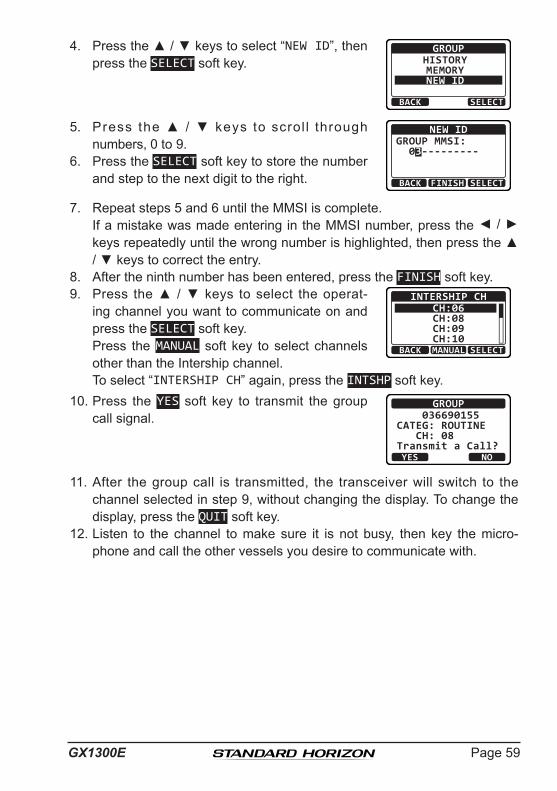
Page 59GX1300E
4. Press the ▲ / ▼ keys to select “NEW ID”, then press the SELECT soft key.
BACK SELECT
GROUPHISTORYMEMORYNEW ID
5. Press the ▲ / ▼ keys to scrol l through numbers, 0 to 9.
BACK SELECTFINISH
NEW IDGROUP MMSI: 03---------
6. Press the SELECT soft key to store the number and step to the next digit to the right.
7. Repeat steps 5 and 6 until the MMSI is complete. If a mistake was made entering in the MMSI number, press the ◄ / ►
keys repeatedly until the wrong number is highlighted, then press the ▲ / ▼ keys to correct the entry.
8. After the ninth number has been entered, press the FINISH soft key.9. Press the ▲ / ▼ keys to select the operat-
ing channel you want to communicate on and press the SELECT soft key.
Press the MANUAL soft key to select channels other than the Intership channel.
BACK SELECT
INTERSHIP CHCH:06CH:08CH:09CH:10MANUAL
To select “INTERSHIP CH” again, press the INTSHP soft key.10. Press the YES soft key to transmit the group
call signal.GROUP
036690155CATEG: ROUTINE CH: 08Transmit a Call?YES NO
11. After the group call is transmitted, the transceiver will switch to the channel selected in step 9, without changing the display. To change the display, press the QUIT soft key.
12. Listen to the channel to make sure it is not busy, then key the micro-phone and call the other vessels you desire to communicate with.

GX1300EPage 60
9.6.3 Receiving a Group Call1. When a group call is received, the GX1300E will produce a ringing alarm
sound. (DSC BEEP needs to be enabled to hear alarm.) The display will show the MMSI (or name) of the vessel transmitting the
group call.2. Press any key to stop the alarm.3. To immediately switch to requested channel,
press the ACCEPT soft key. If a key is not pressed for thirty seconds after
a group call is received, the GX1300E will automatically switch to the requested channel for you to monitor communications.
RX GROUP YAESUCATEG: ROUTINE CH: 08SINCE: 00:05
ACCEPT QUITPAUSE
4. Press the PAUSE soft key to suspend the acknowledgement.
Press the RESUME soft key to resume the acknowledgement.
BUSYMEMAC
USA25W
GROUP PAUSE08
QUITRESUME
5. If you want the radio to stay on the channel you were on before receiv-ing the group call, press the QUIT soft key.
6. Press the ▲ / ▼ keys to scroll the screen and see the MMSI (or name) of the calling vessel, category of the call and requested operating channel.
RX GROUP YAESUCATEG: ROUTINE CH: 08SINCE: 00:08ABLE QUITUNABLE
7. Press the QUIT soft key to display the operat-ing channel number of the requested channel.
8. Listen to the channel for the person calling the group for a message. 9. If you want to respond, monitor the channel to make sure it is clear, then
press the PTT switch on the microphone and talk to the calling ship(s).
NOTE When there is an unread group call, the “ ” icon will appear on
the display. You may review the unread group call from the DSC log, refer to section “9.13.3 Reviewing a Logged Other Calls.”
After a group call is received, the time the call was made and the ships MMSI or vessels name will appear on the LCD.

Page 61GX1300E
9.6.4 Setting up the Group Call RingerThe GX1300E has the capability to turn off the group call ringer.1. Press the MENU key to display the menu.
BACK SELECT
BACK SELECT
SETUPDSC SETUPGROUPCHANNEL SETUPATIS SETUPCONFIGURATION
2. Press the ▲ / ▼ keys to select “SETUP”, then press the SELECT soft key.
3. Press the ▲ / ▼ keys to select “DSC SETUP”, then press the SELECT soft key. (To cancel, press the BACK soft key.)
4. Select “DSC BEEP” with the ▲ / ▼ keys, then press the SELECT soft key.
BACK SELECT
DSC SETUPAUTO POS POLLAUTO POS TIMECH SWITCH TIMERDSC BEEP
5. Select “GROUP ” with the ▲ / ▼ keys, then press the SELECT soft key.
BACK SELECT
DSC BEEPINDIVIDUALGROUPALL SHIPSPOS REQUEST
ONONON
OFF
6. Press the ▲ / ▼ keys to select “OFF”, then press the ENTER soft key.
BACK ENTER
GROUPOFFON
7. Press the 16/S key or press the BACK soft key to return to radio opera-tion mode.
If you wish to return to enabling the ringer tone, just repeat the above proce-dure, pressing the ▲ / ▼ keys to select “ON” in step 6 above.

GX1300EPage 62
9.7 POSITION REQUESTAdvancements in DSC have made it possible to poll the location of another vessel and show the position of that vessel on the display of the GX1300E. Standard Horizon has taken this feature one step further, if any Standard Horizon GPS is connected to the GX1300E, the polled position of the vessel is shown on the display of the GPS chart plotter making it easy to navigate to the location of the polled vessel. This is a great feature for anyone wanting to know the position of another vessel. For example your friend that is catching fish, or finding the location of a person you are cruising with.
NOTE
9.7.1 Transmitting a Position Request to Another VesselPosition Request from Individual / Position Call Directory
1. Press the MENU key to display the menu.
BACK SELECT
BACK SELECT
DSC CALLGROUPALL SHIPSDIST ALERT MSGPOS REQUEST
2. Press the ▲ / ▼ keys to select “DSC”, then press the SELECT soft key.
3. P ress t he ▲ / ▼ keys t o se lec t “P O S REQUEST”, and then press the SELECT soft key. (To cancel, press the BACK soft key.)
4. Press the ▲ / ▼ keys to select “HISTORY” or “MEMORY”, then press the SELECT soft key.
BACK SELECT
POS REQUESTHISTORYMEMORYNEW ID
5. Press the ▲ / ▼ keys to select an individual you want to contact, then press the SELECT soft key.
BACK SELECT
MEMORYYAESUUSCGMEMORY SHIPSHORIZON
The other vessel must have an operating GPS receiver connected to its DSC transceiver and must not have its transceiver set to deny po-sition requests. (Refer the section “9.5.1 Setting up the Individual / Position Call Directory” to enter information into the individual direc-tory).

Page 63GX1300E
6. Press the YES soft key to transmit the position request call.
POS REQUEST YAESUCATEG: SAFETY Transmit a Call?YES NO
7. If the GX1300E does not receive a reply, the display will be as shown in the illustration on the right. To send again, press the RESEND soft key.
POS REQUEST YAESU CATEG: SAFETY SINCE: 00:05[Waiting for ACK]RESEND QUIT
8. When the GX1300E receives the position from the polled vessel, the GX1300E will produce a ringing alarm sound and the position from the polled vessel is sent to a GPS chart plotter via NMEA 0183. (DSC BEEP needs to be enabled to hear alarm.)
Press any key to stop the alarm.9. Press the INFO soft key to show the position
data transferred from the polled vessel on the display.
RX POS REPLYYAESU
POS ACKNOWLEDGED SINCE: 00:05
QUITINFO
10. Press the ▲ / ▼ keys to change the display to view the received data. POS INFO
POS: 23°56.890N 123°56.890WTIME: 12:56 UTC
RX POS REPLY
BACK QUIT
BACK
RX POS REPLY
QUIT
123°56.890W TIME: 12:56 UTC DST: 29.8NM BRG: 270°T
11. To exit from position request display, press the QUIT soft key.
NOTE
If the GX1300E does not receive position data from the polled vessel, the position and time of LCD will show "--".

GX1300EPage 64
Position Request - Manual MMSI EntryYou may enter an MMSI number manually to contact a vessel without storing the MMSI in the individual/position call directory.
1. Press the MENU key to display the menu.
BACK SELECT
BACK SELECT
DSC CALLGROUPALL SHIPSDIST ALERT MSGPOS REQUEST
2. Press the ▲ / ▼ keys to select “DSC”, then press the SELECT soft key.
3. P ress t he ▲ / ▼ keys t o se lec t “P O S REQUEST”, and then press the SELECT soft key. (To cancel, press the BACK soft key.)
4. Press the ▲ / ▼ keys to select “NEW ID”, then press the SELECT soft key.
BACK SELECT
POS REQUESTHISTORYMEMORYNEW ID
5. Press the ▲ / ▼ keys to scrol l through numbers, 0 to 9.
BACK SELECTFINISH
NEW IDMMSI: 3--------
6. Press the SELECT soft key to store the number and step to the next digit to the right.
7. Repeat steps 5 and 6 until the MMSI is complete. If a mistake was made entering in the MMSI number, press the ◄ / ►
keys repeatedly until the wrong number is highlighted, then press the ▲ / ▼ keys to correct the entry.
8. After the ninth number has been entered, press the FINISH soft key.9. Press the YES soft key to transmit the position
request call.POS REQUEST
366901555CATEG: SAFETY Transmit a Call?YES NO
10. If the GX1300E does not receive a reply, the display will be as shown in the illustration on the right. To send again, press the RESEND soft key.
POS REQUEST 366901555 CATEG: SAFETY SINCE: 00:05[Waiting for ACK]RESEND QUIT

Page 65GX1300E
11. When the GX1300E receives the position from the polled vessel, the GX1300E will produce a ringing alarm sound and the position from the polled vessel is sent to a GPS chart plotter via NMEA 0183. (DSC BEEP needs to be enabled to hear alarm.)
Press any key to stop the alarm.12. Press the INFO soft key to show the position
data transferred from the polled vessel on the display.
RX POS REPLY366901555
POS ACKNOWLEDGED SINCE: 00:05
QUITINFO
13. Press the ▲ / ▼ keys to change the display to view the received data. POS INFO
POS: 23°56.890N 123°56.890WTIME: 12:56 UTC
RX POS REPLY
BACK QUIT
BACK
RX POS REPLY
QUIT
123°56.890W TIME: 12:56 UTC DST: 29.8NM BRG: 270°T
14. To exit from position request display, press the QUIT soft key.
NOTE
9.7.2 Receiving a Position RequestWhen a position request call is received from another vessel, a ringing alarm will sound and "POS REQUEST" will be shown in the LCD.
1. When a position request call is received, the GX1300E will transmit your position to the vessel who requested it.
RX POS REQUEST YAESU POS REPLY SINCE: 00:05[ Transmitted ]
QUIT2. To exit from position request display, press the QUIT soft key.
If the GX1300E does not receive position data from the polled vessel, the LCD will show “NO POSITION DATA”.
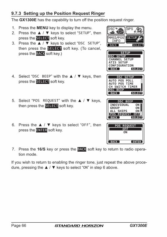
GX1300EPage 66
9.7.3 Setting up the Position Request RingerThe GX1300E has the capability to turn off the position request ringer.
1. Press the MENU key to display the menu.
BACK SELECT
BACK SELECT
SETUPDSC SETUPGROUPCHANNEL SETUPATIS SETUPCONFIGURATION
2. Press the ▲ / ▼ keys to select “SETUP”, then press the SELECT soft key.
3. Press the ▲ / ▼ keys to select “DSC SETUP”, then press the SELECT soft key. (To cancel, press the BACK soft key.)
4. Select “DSC BEEP” with the ▲ / ▼ keys, then press the SELECT soft key.
BACK SELECT
DSC SETUPAUTO POS POLLAUTO POS TIMECH SWITCH TIMERDSC BEEP
5. Select “POS REQUEST” with the ▲ / ▼ keys, then press the SELECT soft key.
BACK SELECT
DSC BEEPINDIVIDUALGROUPALL SHIPSPOS REQUEST
ONONON
OFF
6. Press the ▲ / ▼ keys to select “OFF”, then press the ENTER soft key.
BACK ENTER
POS REQUESTOFFON
7. Press the 16/S key or press the BACK soft key to return to radio opera-tion mode.
If you wish to return to enabling the ringer tone, just repeat the above proce-dure, pressing the ▲ / ▼ keys to select “ON” in step 6 above.

Page 67GX1300E
9.8 POSITION REPORTThe feature is similar to the position request, however instead of requesting a position of another vessel this function allows you to send your position to another vessel. In order to send your position you need to have a GPS receiver connected or to have manually input your position. See section “9.9 MANUAL INPUT OF THE GPS LOCATION.”
9.8.1 Transmitting a DSC Position Report Call
Position Report from Individual / Position Call Directory
1. Press the MENU key to display the menu.
BACK SELECT
BACK SELECT
DSC CALLALL SHIPSDIST ALERT MSGPOS REQUESTPOS REPORT
2. Press the ▲ / ▼ keys to select “DSC”, then press the SELECT soft key.
3. Press the ▲ / ▼ keys to select “POS REPORT”, and then press the SELECT soft key. (To cancel, press the BACK soft key.)
4. Press the ▲ / ▼ keys to select “HISTORY” or “MEMORY”, then press the SELECT soft key.
BACK SELECT
POS REPORTHISTORYMEMORYNEW ID
5. Press the ▲ / ▼ keys to select an individual you want to contact, then press the SELECT soft key.
BACK SELECT
MEMORYYAESUUSCGMEMORY SHIPSHORIZON
6. Press the YES soft key to send your position to the selected vessel.
Press the POS soft key to change the position information.
POS REPORTYAESU
POS: 23°56.890N 123°56.890W
Transmit a Call?YES NOPOS/TM
7. To exit from position request display, press the QUIT soft key.
POS REPORT YAESU CATEG: SAFETY SINCE: 00:05[ Transmitted ]
QUIT
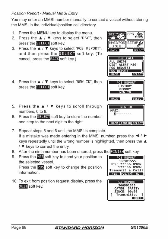
GX1300EPage 68
Position Report - Manual MMSI EntryYou may enter an MMSI number manually to contact a vessel without storing the MMSI in the individual/position call directory.
1. Press the MENU key to display the menu.
BACK SELECT
BACK SELECT
DSC CALLALL SHIPSDIST ALERT MSGPOS REQUESTPOS REPORT
2. Press the ▲ / ▼ keys to select “DSC”, then press the SELECT soft key.
3. Press the ▲ / ▼ keys to select “POS REPORT”, and then press the SELECT soft key. (To cancel, press the BACK soft key.)
4. Press the ▲ / ▼ keys to select “NEW ID”, then press the SELECT soft key.
BACK SELECT
POS REPORTHISTORYMEMORYNEW ID
5. Press the ▲ / ▼ keys to scrol l through numbers, 0 to 9.
BACK SELECTFINISH
NEW IDMMSI: 3--------
6. Press the SELECT soft key to store the number and step to the next digit to the right.
7. Repeat steps 5 and 6 until the MMSI is complete. If a mistake was made entering in the MMSI number, press the ◄ / ►
keys repeatedly until the wrong number is highlighted, then press the ▲ / ▼ keys to correct the entry.
8. After the ninth number has been entered, press the FINISH soft key.9. Press the YES soft key to send your position to
the selected vessel. Press the POS soft key to change the position
information.
POS REPORT366901555
POS: 23°56.890N 123°56.890W
Transmit a Call?YES NOPOS/TM
10. To exit from position request display, press the QUIT soft key.
POS REPORT 366901555 CATEG: SAFETY SINCE: 00:05[ Transmitted ]
QUIT

Page 69GX1300E
9.8.2 Receiving a DSC Position Report CallWhen another vessel transmits their location to the GX1300E the following will happen:
1. When the position report call is received, a ringing sound will be produced and the display shows the vessels MMSI or name, how long since the call was received and the GPS position of the vessel. The GX1300E will also output NMEA sentences (DSC and DSE) to a connected GPS chart plotter.
2. Press any key on the radio to stop the alarm. (DSC BEEP needs to be enabled to hear alarm.)
3. Press the INFO soft key to show the position data transferred from the calling vessel.
RX POS REPORT YAESU POS: 23°56.890N 123°56.890WSINCE: 00:05
QUITINFO
4. Press the ▲ / ▼ keys to change the display to view the received data. POS INFO
POS: 23°56.890N 123°56.890WTIME: 12:56 UTC
RX POS REPORT
BACK QUIT
BACK
RX POS REPORT
QUIT
123°56.890W TIME: 12:56 UTC DST: 29.8 NM BRG: 270°T
5. To exit from position request display, press the QUIT soft key.

GX1300EPage 70
9.8.3 Setting up a Position Report RingerThe GX1300E has the capability to turn off the position report ringer.
1. Press the MENU key to display the menu.
BACK SELECT
BACK SELECT
SETUPDSC SETUPGROUPCHANNEL SETUPATIS SETUPCONFIGURATION
2. Press the ▲ / ▼ keys to select “SETUP”, then press the SELECT soft key.
3. Press the ▲ / ▼ keys to select “DSC SETUP”, then press the SELECT soft key. (To cancel, press the BACK soft key.)
4. Select “DSC BEEP” with the ▲ / ▼ keys, then press the SELECT soft key.
BACK SELECT
DSC SETUPAUTO POS POLLAUTO POS TIMECH SWITCH TIMERDSC BEEP
5. Select “POS REPORT” with the ▲ / ▼ keys, then press the SELECT soft key.
BACK SELECT
DSC BEEPGROUPALL SHIPSPOS REQUESTPOS REPORT
ONON
OFFOFF
6. Press the ▲ / ▼ keys to select “OFF”, then press the ENTER soft key.
BACK ENTER
POS REPORTOFFON
7. Press the 16/S key or press the BACK soft key to return to radio opera-tion mode.
To enable the position report ringer, repeat the above procedure, pressing the ▲ / ▼ keys to select “ON” in step 7 above.
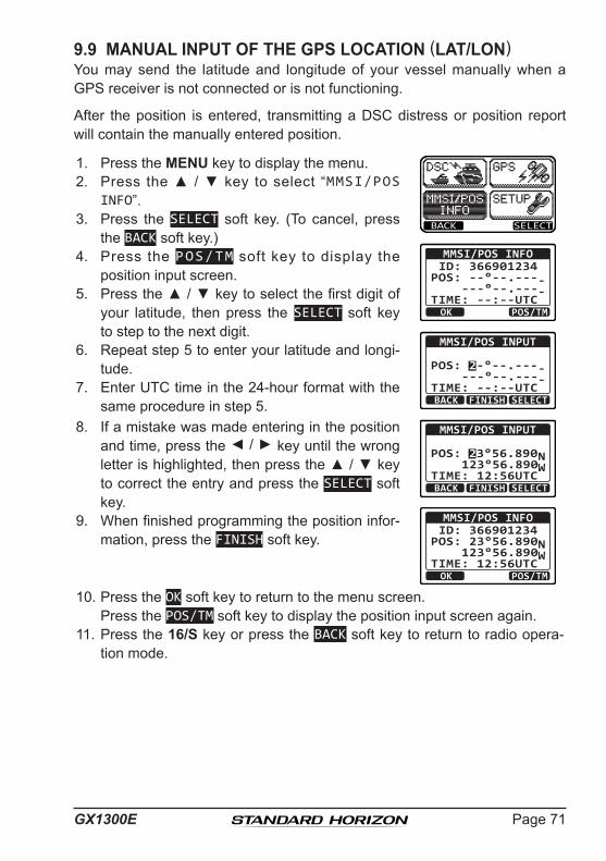
Page 71GX1300E
9.9 MANUAL INPUT OF THE GPS LOCATION (LAT/LON)You may send the latitude and longitude of your vessel manually when a GPS receiver is not connected or is not functioning.
After the position is entered, transmitting a DSC distress or position report will contain the manually entered position.
1. Press the MENU key to display the menu.
BACK SELECT
OK POS/TM
MMSI/POS INFO ID: 366901234
POS: --°--.---- ---°--.----TIME: --:--UTC
BACK SELECT
MMSI/POS INPUT
POS: 2-°--.---- ---°--.----TIME: --:--UTC
FINISH
BACK SELECT
MMSI/POS INPUT
POS: 23°56.890N 123°56.890WTIME: 12:56UTC
FINISH
OK POS/TM
MMSI/POS INFO ID: 366901234
POS: 23°56.890N 123°56.890WTIME: 12:56UTC
2. Press the ▲ / ▼ key to select “MMSI/POS INFO”.
3. Press the SELECT soft key. (To cancel, press the BACK soft key.)
4. Press the POS/TM soft key to display the position input screen.
5. Press the ▲ / ▼ key to select the first digit of your latitude, then press the SELECT soft key to step to the next digit.
6. Repeat step 5 to enter your latitude and longi-tude.
7. Enter UTC time in the 24-hour format with the same procedure in step 5.
8. If a mistake was made entering in the position and time, press the ◄ / ► key until the wrong letter is highlighted, then press the ▲ / ▼ key to correct the entry and press the SELECT soft key.
9. When finished programming the position infor-mation, press the FINISH soft key.
10. Press the OK soft key to return to the menu screen. Press the POS/TM soft key to display the position input screen again.11. Press the 16/S key or press the BACK soft key to return to radio opera-
tion mode.

GX1300EPage 72
9.10 AUTO POS POLLINGThe GX1300E has the capability to automatically track four stations programmed into the individual directory.
9.10.1 Setting up the Polling Call Type1. Press the MENU key to display the menu.
BACK SELECT
BACK SELECT
SETUPDSC SETUPGROUPCHANNEL SETUPATIS SETUPCONFIGURATION
2. Press the ▲ / ▼ keys to select “SETUP”, then press the SELECT soft key.
3. Press the ▲ / ▼ keys to select “DSC SETUP”, then press the SELECT soft key. (To cancel, press the BACK soft key.)
4. Select “AUTO POS POLL” with the ▲ / ▼ keys, then press the SELECT soft key.
BACK SELECT
DSC SETUPAUTO POS POLLAUTO POS TIMECH SWITCH TIMERDSC BEEP
5. Press the ▲ / ▼ keys to select “POS REQUEST” or “POS REPORT”, then press the ENTER soft key.
BACK ENTER
AUTO POS POLLPOS REQUESTPOS REPORT
6. Press the BACK soft key to return to “DSC SETUP”.
9.10.2 Setting up the Polling Time Interval1. Press the MENU key to display the menu.
BACK SELECT
BACK SELECT
SETUPDSC SETUPGROUPCHANNEL SETUPATIS SETUPCONFIGURATION
2. Press the ▲ / ▼ keys to select “SETUP”, then press the SELECT soft key.
3. Press the ▲ / ▼ keys to select “DSC SETUP”, then press the SELECT soft key. (To cancel, press the BACK soft key.)

Page 73GX1300E
4. Select “AUTO POS TIME” with the ▲ / ▼ keys, then press the SELECT soft key.
BACK SELECT
DSC SETUPAUTO POS POLLAUTO POS TIMECH SWITCH TIMERDSC BEEP
5. Press the ▲ / ▼ keys to select the desired interval time, then press the ENTER soft key.
BACK ENTER
AUTO POS TIME30 sec 1 min 2 min 3 min
6. Press the 16/S key or press the BACK soft key to return to radio opera-tion mode.
9.10.3 Selecting Stations to be Automatically Polled1. Press the MENU key to display the menu.
BACK SELECT
BACK SELECT
DSC CALLDIST ALERT MSGPOS REQUESTPOS REPORTAUTO POS POLLING
2. Press the ▲ / ▼ keys to select “DSC”, then press the SELECT soft key.
3. Press the ▲ / ▼ keys to select “AUTO POS POLLING”, and then press the SELECT soft key. (To cancel, press the BACK soft key.)
4. Press the ▲ / ▼ keys to select “SELECT ID”, then press the SELECT soft key.
BACK SELECT
AUTO POS POLLINGACTIVATION START
SELECT ID
5. Press the ▲ / ▼ keys to select the list number, then press the SELECT soft key.
BACK SELECT
SELECT ID1:2:3:4:
6. Press the ▲ / ▼ keys to select an individual you want to poll, then press the SELECT soft key.
BACK SELECT
MEMORYYAESUUSCGMEMORY SHIPSHORIZON

GX1300EPage 74
7. Repeat steps 5 and 6 for all the desired individual to be polled.
BACK SELECT
SELECT ID1:HORIZON2:MEMORY SHIPS3:USCG-24:YAESU-1
8. Press the BACK soft key to return to “AUTO POS POLLING”.
9.10.4 Enabling/Disabling Auto POS Polling1. Press the MENU key to display the menu.
BACK SELECT
BACK SELECT
DSC CALLDIST ALERT MSGPOS REQUESTPOS REPORTAUTO POS POLLING
2. Press the ▲ / ▼ keys to select “DSC”, then press the SELECT soft key.
3. Press the ▲ / ▼ keys to select “AUTO POS POLLING”, and then press the SELECT soft key. (To cancel, press the BACK soft key.)
4. Press the ▲ / ▼ keys to select “ACTIVATION START”, then press the SELECT soft key.
BACK SELECT
AUTO POS POLLINGACTIVATION START
SELECT ID
5. Press the ▲ / ▼ keys to select “START”, then press the SELECT soft key.
BACK SELECT
ACTIVATION STARTSTARTSTOP
6. Press the 16/S key or press the BACK soft key to return to radio opera-tion mode.
To disable the auto position polling, repeat the above procedure, pressing the ▲ / ▼ keys to select “STOP” in step 5 above.
The “A” indicator will appear on the LCD while the auto position polling is activated.
BUSYMEM
LOCAM
AC
USA25W
123˚56.890W 23˚56.890N 09:56
P16

Page 75GX1300E
9.11 DSC TEST CALLThis function is used to contact another DSC equipped vessel to ensure the DSC functions of the radio are operating correctly.
9.11.1 Transmitting a DSC Test Call
DSC Test Call from Individual / Position Call Directory
1. Press the MENU key to display the menu.
BACK SELECT
BACK SELECT
DSC CALLPOS REQUESTPOS REPORTAUTO POS POLLINGTEST CALL
2. Press the ▲ / ▼ keys to select “DSC”, then press the SELECT soft key.
3. Press the ▲ / ▼ keys to select “TEST CALL”, and then press the SELECT soft key. (To cancel, press the BACK soft key.)
4. Press the ▲ / ▼ keys to select “MEMORY”, then press the SELECT soft key.
BACK SELECT
TEST CALLMEMORYNEW ID
5. Press the ▲ / ▼ keys to select an individual you want to contact, then press the SELECT soft key.
BACK SELECT
MEMORYYAESUUSCGMEMORY SHIPSHORIZON
6. Press the YES soft key to transmit the test signal.
TEST CALL YAESU CATEG: SAFETY
Transmit a Call?YES NO
7. After the DSC test call is transmitted, the GX1300E waits for a reply from the radio which was called, and the display will show “WAITING FOR ACK”.
To transmit again, press the RESEND soft key.
TEST CALL YAESU CATEG: SAFETY SINCE: 00:05[Waiting for ACK]RESEND QUIT
8. When an acknowledgement signal is received, the GX1300E will show “RX TEST CALL” screen, which confirms the radio you called has received the test call.
9. Press the QUIT soft key to return to the radio operation.

GX1300EPage 76
DSC Test Call - Manual MMSI Entry
1. Press the MENU key to display the menu.
BACK SELECT
BACK SELECT
DSC CALLPOS REQUESTPOS REPORTAUTO POS POLLINGTEST CALL
2. Press the ▲ / ▼ keys to select “DSC”, then press the SELECT soft key.
3. Press the ▲ / ▼ keys to select “TEST CALL”, and then press the SELECT soft key. (To cancel, press the BACK soft key.)
4. Press the ▲ / ▼ keys to select “NEW ID”, then press the SELECT soft key.
BACK SELECT
TEST CALLMEMORYNEW ID
5. Press the ▲ / ▼ keys to scrol l through numbers, 0 to 9.
BACK SELECTFINISH
NEW IDMMSI: 3--------
6. Press the SELECT soft key to store the number and step to the next digit to the right.
7. Repeat steps 5 and 6 until the MMSI is complete. If a mistake was made entering in the MMSI number, press the ◄ / ►
keys repeatedly until the wrong number is highlighted, then press the ▲ / ▼ keys to correct the entry.
8. After the ninth number has been entered, press the FINISH soft key.9. Press the YES soft key to transmit the test
signal.TEST CALL
366901555 CATEG: SAFETY
Transmit a Call?YES NO
10. After the DSC test call is transmitted, the GX1300E waits for a reply from the radio which was called, and the display will show “WAITING FOR ACK”.
To transmit again, press the RESEND soft key.
TEST CALL 366901555 CATEG: SAFETY SINCE: 00:05[Waiting for ACK]RESEND QUIT
11. When an acknowledgement signal is received, the display will show “Received ACK”.
TEST CALL 366901555 CATEG: SAFETY SINCE: 00:05[ Received ACK ]
QUIT
12. Press the QUIT soft key to return to the radio operation.
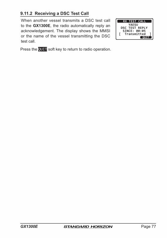
Page 77GX1300E
9.11.2 Receiving a DSC Test CallWhen another vessel transmits a DSC test call to the GX1300E, the radio automatically reply an acknowledgement. The display shows the MMSI or the name of the vessel transmitting the DSC test call.
RX TEST CALL YAESU DSC TEST REPLY SINCE: 00:05[ Transmitted ]
QUIT
Press the QUIT soft key to return to radio operation.

GX1300EPage 78
9.12 POLLING CALLThe GX1300E has the capability to track another vessel.
9.12.1 Transmitting a Polling Call
Position Polling from Individual / Position Call Directory
1. Press the MENU key to display the menu.
BACK SELECT
BACK SELECT
DSC CALLAUTO POS POLLINGTEST CALLPOLLING CALLDSC LOG
2. Press the ▲ / ▼ keys to select “DSC”, then press the SELECT soft key.
3. Press the ▲ / ▼ keys to select “POLLING CALL”, and then press the SELECT soft key. (To cancel, press the BACK soft key.)
4. Press the ▲ / ▼ keys to select “HISTORY” or “MEMORY”, then press the SELECT soft key.
BACK SELECT
POLLING CALLHISTORYMEMORYNEW ID
5. Press the ▲ / ▼ keys to select an individual you want to contact, then press the SELECT soft key.
BACK SELECT
MEMORYYAESUUSCGMEMORY SHIPSHORIZON
6. Press the YES soft key to transmit the polling signal.
POLLING CALL YAESU CATEG: ROUTINE
Transmit a Call?YES NO
7. After the pol l ing cal l is transmitted, the GX1300E waits for a reply from the radio which was called, and the display will show “WAITING FOR ACK”.
To transmit again, press the RESEND soft key.
POLLING CALL YAESU CATEG: ROUTINE SINCE: 00:05[Waiting for ACK]RESEND QUIT
8. When an acknowledgement signal is received, the display will show “Received ACK”.
POLLING CALL YAESU CATEG: ROUTINE SINCE: 00:05[ Received ACK ]
QUIT
9. Press the QUIT soft key to return to the radio operation.

Page 79GX1300E
Position Polling - Manual MMSI Entry1. Press the MENU key to display the menu.
BACK SELECT
BACK SELECT
DSC CALLAUTO POS POLLINGTEST CALLPOLLING CALLDSC LOG
2. Press the ▲ / ▼ keys to select “DSC”, then press the SELECT soft key.
3. Press the ▲ / ▼ keys to select “POLLING CALL”, and then press the SELECT soft key. (To cancel, press the BACK soft key.)
4. Press the ▲ / ▼ keys to select “NEW ID”, then press the SELECT soft key.
BACK SELECT
POLLING CALLHISTORYMEMORYNEW ID
5. Press the ▲ / ▼ keys to scrol l through numbers, 0 to 9.
BACK SELECTFINISH
NEW IDMMSI: 3--------
6. Press the SELECT soft key to store the number and step to the next digit to the right.
7. Repeat steps 5 and 6 until the MMSI is complete. If a mistake was made entering in the MMSI number, press the ◄ / ►
keys repeatedly until the wrong number is highlighted, then press the ▲ / ▼ keys to correct the entry.
8. After the ninth number has been entered, press the FINISH soft key.9. Press the YES soft key to transmit the polling
signal.POLLING CALL
366901555 CATEG: ROUTINE
Transmit a Call?YES NO
10. After the pol l ing cal l is transmitted, the GX1300E waits for a reply from the radio which was called, and the display will show “WAITING FOR ACK”.
To transmit again, press the RESEND soft key.
POLLING CALL 366901555 CATEG: ROUTINE SINCE: 00:05[Waiting for ACK]RESEND QUIT
11. When an acknowledgement signal is received, the display will show “Received ACK”.
POLLING CALL 366901555 CATEG: ROUTINE SINCE: 00:05[ Received ACK ]
QUIT
12. Press the QUIT soft key to return to the radio operation.

GX1300EPage 80
9.12.2 Receiving a Polling CallWhen another vessel transmits a polling call to the GX1300E, the radio automatically reply an acknowledgement. The display shows the MMSI or the name of the vessel transmitting the polling call.
RX POLLING CALL YAESU POLLING REPLY SINCE: 00:05[ Transmitted ]
QUIT
Press the QUIT soft key to return to radio operation.

Page 81GX1300E
9.13 DSC LOG OPERATIONThe GX1300E logs transmitted DSC calls, received distress calls, and other calls (individual, group, all ships, etc.). The DSC log feature is similar to an answer machine where calls are recorded for review and a “ ” icon will appear on the radio's display. The GX1300E can store up to the latest 30 transmitted calls, up to the latest 30 distress calls, and up to the latest 50 other calls.
NOTE
9.13.1 Reviewing a Logged Transmitted Call1. Press the MENU key to display the menu.
BACK SELECT
BACK SELECT
DSC CALLAUTO POS POLLINGTEST CALLPOLLING CALLDSC LOG
2. Press the ▲ / ▼ keys to select “DSC”, then press the SELECT soft key.
3. Press the ▲ / ▼ keys to select “DSC LOG”, and then press the SELECT soft key. (To cancel, press the BACK soft key.)
4. Press the ▲ / ▼ key to select “TRANSMITTED LOG”, then press the SELECT soft key.
BACK SELECT
DSC LOGTRANSMITTED LOGDISTRESS LOG
OTHER CALL LOGLOG DELETE
5. Press the ▲ / ▼ key to select the station (name or MMSI number) you want to review the call, then press the SELECT soft key.
BACK SELECT
TRANSMITTED LOGHORIZONMEMORY SHIPSUSCGYAESU
When the “DSC LOG” menu is selected, the GX1300E will display the highest priority logged calls automatically.

GX1300EPage 82
6. Press the ▲ / ▼ key to scroll the display.
BACK DELETE
TRANSMITTED LOGINDIVIDUAL123456789YAESU
TX TM: 12:56 UTC
BACK DELETE
TRANSMITTED LOGDATE: 12/JAN
CATER: ROUTINECH: 06
[ Delayed ACK ]
7. Press the BACK soft key to go back to the DSC transmitted call list.
9.13.2 Reviewing a Logged DSC Distress Call1. Press the MENU key to display the menu.
BACK SELECT
BACK SELECT
DSC CALLAUTO POS POLLINGTEST CALLPOLLING CALLDSC LOG
2. Press the ▲ / ▼ keys to select “DSC”, then press the SELECT soft key.
3. Press the ▲ / ▼ keys to select “DSC LOG”, and then press the SELECT soft key. (To cancel, press the BACK soft key.)
4. Press the ▲ / ▼ key to select “DISTRESS LOG”, then press the SELECT soft key.
BACK SELECT
DSC LOGTRANSMITTED LOGDISTRESS LOG
OTHER CALL LOGLOG DELETE
5. Press the ▲ / ▼ key to select the station (name or MMSI number) you want to review.
Note: When there is an unread received call, “ ” icon will appear at the head of the station name (or MMSI number).
BACK SELECT
DISTRESS LOGHORIZONMEMORY SHIPSUSCGYAESU
Press the SELECT soft key to review details for the selected station.

Page 83GX1300E
6. Press the ▲ / ▼ key to scroll the display.
BACK DELETE
DISTRESS LOG123456789YAESU
RX TM: 12:56 UTCDATE: 12/JAN
BACK DELETE
DISTRESS LOGDATE: 12/JAN
CATER: ROUTINECH: 06
[ Delayed ACK ]
7. Press the BACK soft key to go back to the DSC distress call list.
9.13.3 Reviewing a Logged Other CallsThe GX1300E allows received calls (individual, group, all ships, etc.) to be reviewed.
1. Press the MENU key to display the menu.
BACK SELECT
BACK SELECT
DSC CALLAUTO POS POLLINGTEST CALLPOLLING CALLDSC LOG
2. Press the ▲ / ▼ keys to select “DSC”, then press the SELECT soft key.
3. Press the ▲ / ▼ keys to select “DSC LOG”, and then press the SELECT soft key. (To cancel, press the BACK soft key.)
4. Press the ▲ / ▼ key to select “OTHER CALL LOG”, then press the SELECT soft key.
BACK SELECT
DSC LOGTRANSMITTED LOGDISTRESS LOG
OTHER CALL LOGLOG DELETE
5. Press the ▲ / ▼ key to select the station (name or MMSI number) you want to review.
Note: When there is an unread received call, “ ” icon will appear at the head of the station name (or MMSI number).
BACK SELECT
OTHER CALL LOGHORIZONMEMORY SHIPSUSCGYAESU
Press the SELECT soft key, to review details for the selected station.

GX1300EPage 84
6. Press the ▲ / ▼ key to scroll the display.
BACK DELETE
RX OTHER LOGINDIVIDUAL123456789YAESU
RX TM: 12:56 UTC
BACK DELETE
RX OTHER LOGDATE: 12/JAN
CATER: ROUTINECH: 06
[ Delayed ACK ]
7. Press the BACK soft key to go back to the DSC other call list.
9.13.4 Deleting Calls from the “DSC LOG” Directory1. Press the MENU key to display the menu.
BACK SELECT
BACK SELECT
DSC CALLAUTO POS POLLINGTEST CALLPOLLING CALLDSC LOG
2. Press the ▲ / ▼ keys to select “DSC”, then press the SELECT soft key.
3. Press the ▲ / ▼ keys to select “DSC LOG”, and then press the SELECT soft key. (To cancel, press the BACK soft key.)
4. Press the ▲ / ▼ key to select “LOG DELETE”, then press the SELECT soft key.
BACK SELECT
DSC LOGTRANSMITTED LOGDISTRESS LOG
OTHER CALL LOGLOG DELETE
5. Press the ▲ / ▼ key to select the category (“TRANSMITTED LOG”, “DISTRESS LOG”, “OTHER CALL LOG”, or “ALL LOG”) to be deleted, then press the SELECT soft key. BACK SELECT
LOG DELETETRANSMITTED LOGDISTRESS LOGOTHER CALL LOGALL LOG
6. Press the YES soft key to delete logs of the selected category. (To cancel, press the NO soft key.)
YES NO
LOG DELETETRANSMITTED LOG
Do you want todelete it?

Page 85GX1300E
7. Press the OK soft key to go back to the catego-ry list.
OK
LOG DELETETRANSMITTED LOG
Complete
NOTE
The procedure above will delete logged calls of the selected category all at once.
To delete logged calls one by one, review details of a call you want to delete, then press the DELETE soft key.

GX1300EPage 86
10 SETUP MENU10.1 CONFIGURATION SETUP10.1.1 Lamp AdjustmentAllows adjustment of the backlight intensity or to turn it off.
1. Press the MENU key to display the menu.
BACK SELECT
BACK SELECT
SETUPDSC SETUPCHANNEL SETUPATIS SETUPCONFIGURATION
2. Press the ▲ / ▼ keys to select “SETUP”, then press the SELECT soft key.
3. Press the ▲ / ▼ keys to select “CONFIGURA-TION”, then press the SELECT soft key.
4. Select “DIMMER” with the ▲ / ▼ keys, then press the SELECT soft key.
BACK SELECT
CONFIGURATIONDIMMERCONTRASTKEY BEEPLOCATION FORMT
5. Press the ▲ / ▼ keys to select the desired level. When “OFF” is selected, the lamp is extinguished. 5
BACK ENTER
DIMMER
6. Press the ENTER soft key to store the selected level.
7. To exit this menu and return to radio operation press the BACK soft key.
10.1.2 LCD ContrastThis selection sets up the display contract to optimize the viewing angle for the varying mounting locations (overhead or below).
1. Press the MENU key to display the menu.
BACK SELECT
BACK SELECT
SETUPDSC SETUPCHANNEL SETUPATIS SETUPCONFIGURATION
2. Press the ▲ / ▼ keys to select “SETUP”, then press the SELECT soft key.
3. Press the ▲ / ▼ keys to select “CONFIGURA-TION”, then press the SELECT soft key.

Page 87GX1300E
4. Select “CONTRAST” with the ▲ / ▼ keys, then press the SELECT soft key.
BACK SELECT
CONFIGURATIONDIMMERCONTRASTKEY BEEPLOCATION FORMT
5. Press the ▲ / ▼ keys to select the desired level. The contrast level can be set from “00” to “25”. 25
BACK ENTER
CONTRAST
6. Press the ENTER soft key to store the selected level.
7. To exit this menu and return to radio operation press the BACK soft key.
10.1.3 Key BeepThis section allows the level of the key beep to be adjusted or turned off.
1. Press the MENU key to display the menu.
BACK SELECT
BACK SELECT
SETUPDSC SETUPCHANNEL SETUPATIS SETUPCONFIGURATION
2. Press the ▲ / ▼ keys to select “SETUP”, then press the SELECT soft key.
3. Press the ▲ / ▼ keys to select “CONFIGURA-TION”, then press the SELECT soft key.
4. Select “KEY BEEP” with the ▲ / ▼ keys, then press the SELECT soft key.
BACK SELECT
CONFIGURATIONDIMMERCONTRASTKEY BEEPLOCATION FORMT
5. Press the ▲ / ▼ keys to select the desired beep level. The key beep level can be set from “0” (OFF) to “5”. 5
BACK ENTER
KEY BEEP
6. Press the ENTER soft key to store the selected level.
7. To exit this menu and return to radio operation press the BACK soft key.
NOTE
Emergency alarm and beeps for DSC operation cannot be turned OFF.

GX1300EPage 88
10.1.4 Location FormatThis selection sets the coordinate system to be shown on the LCD.
1. Press the MENU key to display the menu.
BACK SELECT
BACK SELECT
SETUPDSC SETUPCHANNEL SETUPATIS SETUPCONFIGURATION
2. Press the ▲ / ▼ keys to select “SETUP”, then press the SELECT soft key.
3. Press the ▲ / ▼ keys to select “CONFIGURA-TION”, then press the SELECT soft key.
4. Select “LOCATION FORMAT” with the ▲ / ▼ keys, then press the SELECT soft key.
BACK SELECT
CONFIGURATIONDIMMERCONTRASTKEY BEEPLOCATION FORMT
5. Press the ▲ / ▼ keys to select the desired coordinate system.
BACK ENTER
LOCATION FORMATdd°mm.mmmdd°mm.mm dd°mm’SS”6. Press the ENTER soft key to store the selected
level.
7. To exit this menu and return to radio operation press the BACK soft key.
10.1.5 Time OffsetThis selection sets the time offset from UTC (time GPS sends to radio).Refer to section “6.6 CHANGING THE GPS TIME” for details.
10.1.6 Time DisplayThis selection selects the time area between the local time and the UTC time.Refer to section “6.7 CHANGING THE TIME LOCATION” for details.
10.1.7 Time FormatThis selection selects the time format between the 12-hour system and the 24-hour system.Refer to section “6.8 CHANGING THE TIME FORMAT” for details.

Page 89GX1300E
10.1.8 Unit Of MeasureThis selection sets the distance units.
1. Press the MENU key to display the menu.
BACK SELECT
BACK SELECT
SETUPDSC SETUPCHANNEL SETUPATIS SETUPCONFIGURATION
2. Press the ▲ / ▼ keys to select “SETUP”, then press the SELECT soft key.
3. Press the ▲ / ▼ keys to select “CONFIGURA-TION”, then press the SELECT soft key.
4. Select “UNIT OF MEASURE” with the ▲ / ▼ keys, then press the SELECT soft key.
BACK SELECT
CONFIGURATIONTIME AREATIME FORMATUNIT OF MEASURESOFT KEY
5. Press the ▲ / ▼ keys to select “DISTANCE”, then press the SELECT soft key.
BACK ENTER
UNIT OF MEASUREDISTANCE nm
6. Press the ▲ / ▼ keys to select the unit.
BACK ENTER
DISTANCEstatute milenautical mile
kilometer7. Press the ENTER soft key to store the new
setting.
8. To exit this menu and return to radio operation press the BACK soft key.

GX1300EPage 90
10.1.9 Soft KeysThis menu item assigns the number of soft keys, soft key selection and how long the display will show the soft key icon after a soft key is pressed.
Assigning Soft Keys
1. Press the MENU key to display the menu.
BACK SELECT
BACK SELECT
SETUPDSC SETUPCHANNEL SETUPATIS SETUPCONFIGURATION
2. Press the ▲ / ▼ keys to select “SETUP”, then press the SELECT soft key.
3. Press the ▲ / ▼ keys to select “CONFIGURA-TION”, then press the SELECT soft key.
4. Select “SOFT KEY” with the ▲ / ▼ keys, then press the SELECT soft key.
BACK SELECT
CONFIGURATIONTIME FORMATUMIT OF MEASURESOFT KEYRESET
5. Press the ▲ / ▼ keys to select “KEY ASSIGN-MENT”, then press the SELECT soft key.
BACK SELECT
SOFT KEYKEY ASSIGNMENT
KEY TIMMER
6. Press the ▲ / ▼ keys to select the desired soft key number, then press the SELECT soft key.
BACK ENTER
KEY ASSIGNMENT1: SCAN2: WX/CH3: SCAN MEMORY4: DW/TW
7. Press the ▲ / ▼ keys to select the desired key function, then press the ENTER soft key.
Refer to the next page for available functions.BACK ENTER
KEY SELECTIONNONEWX/CHSCANDW/TW
8. Repeat steps 6 and 7 to assign up to 6 functions.9. To exit this menu and return to radio operation press the BACK soft key.
NOTE
Key function "WX/CH" is displayed to only USA version.

Page 91GX1300E
Available functions are: DISPLAY FUNCTION
SCAN Starts and stops scanning.DW/TW Starts and stops the dual or triple watch scan.
SCAN MEMORY Switches on and off of the memory channel scan.PRESET Saves or deletes the preset memory channel.
GPS STATUS GPS status display
Selecting How Long the Soft Keys are Shown
1. Press the MENU key to display the menu.
BACK SELECT
BACK SELECT
SETUPDSC SETUPCHANNEL SETUPATIS SETUPCONFIGURATION
2. Press the ▲ / ▼ keys to select “SETUP”, then press the SELECT soft key.
3. Press the ▲ / ▼ keys to select “CONFIGURA-TION”, then press the SELECT soft key.
4. Select “SOFT KEY” with the ▲ / ▼ keys, then press the SELECT soft key.
BACK SELECT
CONFIGURATIONTIME FORMATUMIT OF MEASURESOFT KEYRESET
5. Press the ▲ / ▼ keys to select “KEY TIMER”, then press the SELECT soft key.
BACK SELECT
SOFT KEYKEY ASSIGNMENT
KEY TIMMER
6. Press the ▲ / ▼ keys to select how long the soft key icon will be shown on the display after a soft key is pressed, then press the ENTER soft key.
The showing time can be set to “3 sec”, “5 sec”, “7 sec”, “10 sec”, or “15 sec”.
BACK ENTER
KEY TIMMER3 sec5 sec7 sec
10 sec
7. To exit this menu and return to radio operation press the BACK soft key.

GX1300EPage 92
10.2 CHANNEL SETUP10.2.1 Channel Group (Band Selection)This selection allows you to change the channel group from International to USA or Canada.Refer to section “8.5 USA, INTERNATIONAL, AND CANADA MODE” for details.
10.2.2 Multi WatchAllows selection of the dual and triple watch functions.Refer to section “8.7 MULTI WATCH (TO PRIORITY CHANNEL)” for details.
10.2.3 Scan MemoryTo be able to scan channels the radio must be programmed. This section allows channels to be stored in scan memory.Refer to section “8.6.2 Scan Memory Programming” for details.
10.2.4 Scan TypeThis selection is used to select the scan mode between “Memory Scan” and “Priority Scan”. Refer to section “8.6.1 Selecting the Scan Type” for details.
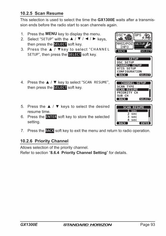
Page 93GX1300E
10.2.5 Scan ResumeThis selection is used to select the time the GX1300E waits after a transmis-sion ends before the radio start to scan channels again.
1. Press the MENU key to display the menu.
BACK SELECT
BACK SELECT
SETUPDSC SETUPCHANNEL SETUPATIS SETUPCONFIGURATION
2. Select “SETUP” with the ▲ / ▼ / ◄ / ► keys, then press the SELECT soft key.
3. Press the ▲ / ▼key to select “CHANNEL SETUP”, then press the SELECT soft key.
4. Press the ▲ / ▼ key to select “SCAN RESUME”, then press the SELECT soft key.
BACK SELECT
CHANNEL SETUPSCAN TYPESCAN RESUMEPRIORITY CHSUB CH
5. Press the ▲ / ▼ keys to select the desired resume time.
BACK ENTER
SCAN RESUME1 sec2 sec3 sec4 sec
6. Press the ENTER soft key to store the selected setting.
7. Press the BACK soft key to exit the menu and return to radio operation.
10.2.6 Priority ChannelAllows selection of the priority channel.Refer to section “8.6.4 Priority Channel Setting” for details.
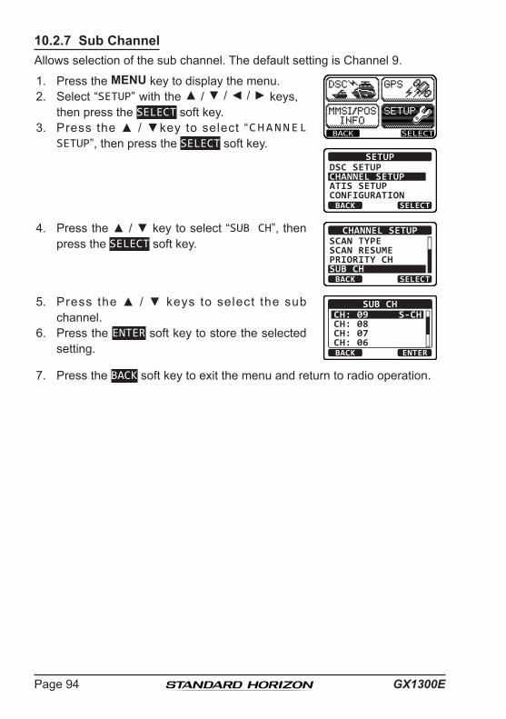
GX1300EPage 94
10.2.7 Sub ChannelAllows selection of the sub channel. The default setting is Channel 9.
1. Press the MENU key to display the menu.
BACK SELECT
BACK SELECT
SETUPDSC SETUPCHANNEL SETUPATIS SETUPCONFIGURATION
2. Select “SETUP” with the ▲ / ▼ / ◄ / ► keys, then press the SELECT soft key.
3. Press the ▲ / ▼key to select “CHANNEL SETUP”, then press the SELECT soft key.
4. Press the ▲ / ▼ key to select “SUB CH”, then press the SELECT soft key.
BACK SELECT
CHANNEL SETUPSCAN TYPESCAN RESUMEPRIORITY CHSUB CH
5. Press the ▲ / ▼ keys to select the sub channel.
BACK ENTER
SUB CHCH: 09CH: 08CH: 07CH: 06
S-CH
6. Press the ENTER soft key to store the selected setting.
7. Press the BACK soft key to exit the menu and return to radio operation.

Page 95GX1300E
10.3 DSC SETUP10.3.1 Individual DirectoryThe GX1300E has a DSC directory that allows you to store a vessel or person’s name and the MMSI number associated with vessels you wish to transmit individual calls, position requests and position report transmissions.
To transmit an individual call you must program this directory with information of the persons you wish to call, similar to a cellular phones telephone direc-tory.
Refer to section “9.5.1 Setting up the Individual / Position Call Directory” for programming.
10.3.2 Individual ReplyThis menu item sets up the radio to automatically or manually (default setting) respond to a DSC individual call requesting you to switch to a working channel for voice communications. When the manual response is selected the MMSI of the calling vessel is shown allowing you to see who is calling. This function is similar to caller ID on a cellular phone.
Refer to section “9.5.2 Setting up Individual Call Reply” for setting.
10.3.3 Individual AcknowledgementThe radio can be setup to transmit a reply automatically or set so the radio will not reply to an individual call.
Refer to section “9.5.3 Setting up the Individual Acknowledge Message” for setting.
10.3.4 Individual RingerThe radio can be setup to ring like a telephone to alert you the radio received a DSC individual call. The default setting is 2 minutes, however this can be changed to 15, 10 or 5 seconds.
Refer to section “9.5.6 Setting up Individual Call Ringer” for setting.

GX1300EPage 96
10.3.5 Group DirectoryFor this function to operate, the same group MMSI must be programmed into all the DSC VHF radios within the group of vessels that will be using this feature. To understand group MMSI programming, first a ship MMSI has to be understood.
Refer to section “9.6.1 Setting up a Group Call” for programming.
10.3.6 Auto Position Polling Call TypeThe GX1300E has the capability to automatically track four vessels programmed into the individual directory. This selection allows you to select the call type used in the auto position polling.
Refer to section “9.10.1 Setting up the Polling Call Type” for setting.
10.3.7 Auto Position Polling Interval TimeThe GX1300E has the capability to automatically track four vessels programmed into the individual directory. This selection allows you to select time interval between polling call transmissions.
Refer to section “9.10.2 Setting up the Polling Time Interval” for setting.

Page 97GX1300E
10.3.8 Auto Channel Switching TimeWhen a DSC distress call or an all ships call (urgency or safety) is received, the GX1300E will automatically switch to the channel 16.This menu selection allows the automatic switching time to be changed.
1. Press the MENU key to display the menu.
BACK SELECT
BACK SELECT
SETUPDSC SETUPGROUPCHANNEL SETUPATIS SETUPCONFIGURATION
2. Press the ▲ / ▼ keys to select “SETUP”, then press the SELECT soft key.
3. Press the ▲ / ▼ keys to select “DSC SETUP”, then press the SELECT soft key. (To cancel, press the BACK soft key.)
4. Select “CH SWITCH TIMER” with the ▲ / ▼ keys, then press the SELECT soft key.
BACK SELECT
DSC SETUPAUTP POS POLLAUTO POS TIMECH SWITCH TIMERDSC BEEP
5. Press the ▲ / ▼ keys to select the desired time, then press the ENTER soft key. The switching time can be set to “OFF”, “10 sec”, “30 sec”, “1 min”, or “2 min”. BACK ENTER
CH SWITCH TIMEROFF
10 sec30 sec 1 min
6. Press the BACK soft key to exit the menu and return to radio operation.
10.3.9 DSC BeepThis feature allows the alarm beeps to be turned on (default setting) or off when a DSC call is received. The DSC calls that can be customized are: individual, group, all ships, position request, position report call.
Refer to section “9.6.4 Setting up the Group Call Ringer” for setting.

GX1300EPage 98
10.4 ATIS SETUPThe GX1300E supports the ATIS (Automatic Transmitter Identification System) used in Inland waterways in Europe. When enabled ATIS mode transmits a unique ATIS code each time the Microphone’s PTT switch is released at the end of a transmission. Users should check with their local marine regulatory authority in their country for assistance in obtaining an ATIS code.
10.4.1 ATIS Code Programming1. Press the MENU key to display the menu.
BACK SELECT
BACK SELECT
SETUPDSC SETUPCHANNEL SETUPATIS SETUPCONFIGURATION
2. Press the ▲ / ▼ keys to select “SETUP”, then press the SELECT soft key.
3. Press the ▲ / ▼ keys to select “ATIS SETUP”, and then press the SELECT soft key. (To cancel, press the BACK soft key.)
4. Press the ▲ / ▼ keys to select “ATIS CODE”, then press the SELECT soft key.
BACK SELECT
ATIS SETUPATIS CODEATIS GROUP
5. Press the ▲ / ▼ key to select the first number of your ATIS code, then press the SELECT soft key to step to the next number.
ATIS CODE INPUT 1st: ----------
BACK FINISH SELECT6. Repeat step 5 to set your ATIS code (ten digits).
7. If a mistake was made entering in the ATIS code, press the ◄ / ► key until the wrong number is highlighted, then press the ▲ / ▼ key to correct the entry and press the SELECT soft key.
8. After the tenth number has been entered, press the FINISH soft key.
The radio will ask you to input the ATIS code again. Use steps 5 through 7 above.
ATIS CODE INPUT 1st: **********
---------- 2nd:
BACK SELECTFINISH
9. After the second number has been input, press the FINISH soft key to store the ATIS code.

Page 99GX1300E
10. Press the OK soft key to return to the “ATIS SETUP” screen.
ATIS CODE INPUT
STORED CODE
9366901230
OK
11. Press the BACK soft key to exit the menu and return to radio operation.
10.4.2 ATIS Channel GroupThe GX1300E has the capability to turn on and off the ATIS feature for each channel group.
1. Press the MENU key to display the menu.
BACK SELECT
BACK SELECT
SETUPDSC SETUPCHANNEL SETUPATIS SETUPCONFIGURATION
2. Press the ▲ / ▼ keys to select “SETUP”, then press the SELECT soft key.
3. Press the ▲ / ▼ keys to select “ATIS SETUP”, and then press the SELECT soft key. (To cancel, press the BACK soft key.)
4. Press the ▲ / ▼ keys to select “ATIS GROUP”, then press the SELECT soft key.
BACK SELECT
ATIS SETUPATIS CODEATIS GROUP
5. Press the ▲ / ▼ keys to select the desired channel group, then press the SELECT soft key.
BACK SELECT
ATIS GROUPUSAINTLCAN
OFFOFFOFF
6. Press the ▲ / ▼ keys to select “OFF” or “ON”, then press the ENTER soft key.
BACK ENTER
USAOFFON
7. Press the BACK soft key to exit the menu and return to radio operation.NOTE
The TX output power is set to “1W” automatically on the following channels of the Channel Group which turned on the ATIS feature.CH 06, 08, 10, 11, 12, 13, 14, 15, 17, 71, 72, 74, 75, 76, and 77
The “Scan” and “MULTI Watch” features are not available on the channel group while the ATIS feature is turned on.

GX1300EPage 100
11 MAINTENANCEThe inherent quality of the solid-state components used in this transceiver will provide many years of continuous use. Taking the following precautions however, will prevent damage to the transceiver.
• Never key the microphone unless an antenna or suitable dummy load is connected to the transceiver.
• Ensure that the supply voltage to the transceiver does not exceed 16 VDC or fall below 11 VDC.
• Use only STANDARD HORIZON-approved accessories and replacement parts.
In the unlikely event of serious problems, please contact your Dealer or our repair facility.
11.1 REPLACEMENT PARTSCommonly requested parts, and their part numbers are listed below.• Power Cord: T9025406• VOL/SQL Knob (Black): RA6045800• VOL/SQL Knob (White): RA6045700• Mounting Bracket (Black): RA097840A• Mounting Bracket (White): RA097830A• Mounting Bracket Knob (Black): RA0978600• Mounting Bracket Knob (White): RA0978500• Microphone Hanger (Black): RA0458800• Microphone Hanger (White): RA0436000
11.2 FACTORY SERVICEIn the unlikely event that the radio fails to perform or needs servicing, please contact your dealer.
An “RA” (Return Authorization) number is not necessary to send a product in for service. Include a brief note describing the problem along with your name, return address, phone number, and proof of purchase.

Page 101GX1300E
11.3 TROUBLESHOOTING CHARTSYMPTOM PROBABLE CAUSE REMEDY
Transceiver fails to power up.
No DC voltage to the transceiver, or blown fuse.
a. Check the 12 VDC battery connections and the fuse.
b. The VOL knob needs to be rotated clock-wise to turn the radio on.
Transce iver b lows fuse when connected to power supply.
R e v e r s e d p o w e r wires.
Check the power cable for DC voltage, or re-place the fuse (6 A 250 V).Make sure the red wire is connected to the positive (+) battery post, and the black wire is connected to the negative (-) battery post. If the fuse still blows, contact your Dealer.
Popping or whining noise from the speak-er while engine runs.
Engine noise. Reroute the DC power cables away from the engine. Add noise suppressor on power cable. Change to resistive spark plug wires and/or add an alternator whine filter.
Sound is not emitted from the internal or external speaker.
Accessory cable. Check the connections of the accessory cable (Possible short circuit on the External speaker cable WHITE/SHIELD).
R e c e i v i n g s t a t i o n report low transmit p o w e r, e v e n w i t h transceiver set to HI power.
Antenna. Have the antenna checked or test the trans-ceiver with another antenna. If the problem persists, contact your Dealer for servicing.
“HI BATTERY” or “LO BATTERY” message is appeared when the power is turned on.
The power supp l y voltage is too high or too low.
Confirm that the connected power supply volt-age is between 11 volts and 16.6 volts DC. Confirm that the generator has not malfunc-tioned.
Your position is not displayed.
Accessory cable. Check the accessory cable connection.Some GPS use the battery ground line for NMEA connection.
Sett ing of the GPS navigation receiver.
Check the output signal format of the GPS navigation receiver. This radio requires NMEA0183 format with GLL, RMC, GGA, or GNS sentence as an output signal. If the GPS has a baud rate setting make sure to select 4800 and parity to NONE.

GX1300EPage 102
12 CHANNEL ASSIGNMENTSCH TX (MHz) RX (MHz) SIMPLEX/DUPLEX LOW PWR CHANNEL USE01 156.050 160.650 DUPLEX – TELEPHONE02 156.100 160.700 DUPLEX – TELEPHONE03 156.150 160.750 DUPLEX – TELEPHONE04 156.200 160.800 DUPLEX – INTL05 156.250 160.850 DUPLEX – INTL06 156.300 156.300 SIMPLEX – SAFETY07 156.350 160.950 DUPLEX – INTL08 156.400 156.400 SIMPLEX – COMMERCIAL09 156.450 156.450 SIMPLEX – CALLING10 156.500 156.500 SIMPLEX – COMMERCIAL11 156.550 156.550 SIMPLEX – VTS12 156.600 156.600 SIMPLEX – VTS13 156.650 156.650 SIMPLEX – BRG/BRG14 156.700 156.700 SIMPLEX – VTS15 156.750 156.750 SIMPLEX LOW COMMERCIAL16 156.800 156.800 SIMPLEX – DISTRESS17 156.850 156.850 SIMPLEX LOW SAR18 156.900 161.500 DUPLEX – INTL19 156.950 161.550 DUPLEX – INTL20 157.000 161.600 DUPLEX – PORT OPR21 157.050 161.650 DUPLEX – INTL22 157.100 161.700 DUPLEX – INTL23 157.150 161.750 DUPLEX – INTL24 157.200 161.800 DUPLEX – TELEPHONE25 157.250 161.850 DUPLEX – TELEPHONE26 157.300 161.900 DUPLEX – TELEPHONE27 157.350 161.950 DUPLEX – TELEPHONE28 157.400 162.000 DUPLEX – TELEPHONE60 156.025 160.625 DUPLEX – TELEPHONE61 156.075 160.675 DUPLEX – INTL62 156.125 160.725 DUPLEX – INTL63 156.175 160.775 DUPLEX – INTL64 156.225 160.825 DUPLEX – TELEPHONE65 156.275 160.875 DUPLEX – INTL66 156.325 160.925 DUPLEX – INTL67 156.375 156.375 SIMPLEX – BRG/BRG68 156.425 156.425 SIMPLEX – SHIP-SHIP69 156.475 156.475 SIMPLEX – PLEAURE70 - 156.525 SIMPLEX – DSC71 156.575 156.575 SIMPLEX – PLEASURE72 156.625 156.625 SIMPLEX – SHIP-SHIP73 156.675 156.675 SIMPLEX – PORT OPR74 156.725 156.725 SIMPLEX – PORT OPR75 156.775 156.775 SIMPLEX LOW PORT OPR

Page 103GX1300E
CH TX (MHz) RX (MHz) SIMPLEX/DUPLEX LOW PWR CHANNEL USE76 156.825 156.825 SIMPLEX LOW PORT OPR77 156.875 156.875 SIMPLEX – PORT OPR78 156.925 161.525 DUPLEX – INTL79 156.975 161.575 DUPLEX – INTL80 157.025 161.625 DUPLEX – INTL81 157.075 161.675 DUPLEX – INTL82 157.125 161.725 DUPLEX – INTL83 157.175 161.775 DUPLEX – INTL84 157.225 161.825 DUPLEX – TELEPHONE85 157.275 161.875 DUPLEX – TELEPHONE86 157.325 161.925 DUPLEX – TELEPHONE87 157.375 157.375 SIMPLEX – PORT OPR88 157.425 157.425 SIMPLEX – PORT OPRM1 157.850 157.850 SIMPLEX – –M2 161.425 161.425 SIMPLEX – –
NOTE 1: Channel M1 and M2 are assigned to only U.K. version. 2: Channel Asignment is different depending on the transceiver version.

GX1300EPage 104
13 WARRANTYPLEASE NOTE
To receive warranty service in Europe, for European Sourced products, the purchaser must return the Product, shipment and insurance prepaid to the purchasing dealer or authorized Service Centre in Europe. Contact details for warranty in Europe are available from the dealer in your coun-try or from www.standardhorizon.co.uk where details of warranty terms and contact details for Europe can be obtained.
STANDARD HORIZON LIMITED WARRANTYSTANDARD HORIZON (the Marine Division of Yaesu Musen Co. Ltd) warrants, to the original purchaser only, each new Marine Product (“Product”) manufactured and/or supplied by STANDARD HORIZON against defects in materials and workmanship under normal use and service for a period of 3 years from the date of purchase.
In the event of a defect, malfunction or failure of the Product during the warranty period, STANDARD HORIZON’s liability for any breach of contract or any breach of express or implied warranties in connection with the sale of Products shall be limited solely to repair or replacement, at its option, of the Product or part(s) therein which, upon examination by STANDARD HORIZON, appear to be defective or not up to factory specifications. STANDARD HORIZON may, at its option, repair or replace parts or subas-semblies with new or reconditioned parts and subassemblies.
STANDARD HORIZON will not warrant installation, maintenance or service of the Products. In all instances, STANDARD HORIZON’s liability for damag-es shall not exceed the purchase price of the defective Product.
STANDARD HORIZON will pay all labor and replacement parts charges incurred in providing the warranty repair service except where purchaser abuse or other qualifying exceptions exist. The purchaser must pay any transportation expenses incurred in returning the Product to STANDARD HORIZON for service.
This limited warranty does not extend to any Product which has been subjected to misuse, neglect, accident, incorrect wiring by anyone other than STANDARD HORIZON, improper installation, or subjected to use in violation of instructions furnished by STANDARD HORIZON, nor does this warranty extend to Products on which the serial number has been removed,

Page 105GX1300E
defaced, or changed. STANDARD HORIZON cannot be responsible in any way for ancillary equipment not furnished by STANDARD HORIZON which is attached to or used in connection with Products, or for the operation of the Product with any ancillary equipment and all such equipment is expressly excluded from this warranty.
STANDARD HORIZON disclaims liability for range, coverage, or operation of the Product and ancillary equipment as a whole under this warranty.
STANDARD HORIZON reserves the right to make changes or improvements in Products, during subsequent production, without incurring the obliga-tion to install such changes or improvements on previously manufactured Products. The implied warranties which the law imposes on the sale of this Product are expressly LIMITED, in duration, to the time period speci-fied above. STANDARD HORIZON shall not be liable under any circum-stances for consequential damages resulting from the use and operation of this Product, or from the breach of this LIMITED WARRANTY, any implied warranties, or any contract with STANDARD HORIZON. IN CONNECTION WITH THE SALE OF ITS PRODUCTS, STANDARD HORIZON MAKES NO WARRANTIES, EXPRESS OR IMPLIED AS TO THE MERCHANTABILITY OR FITNESS FOR A PARTICULAR PURPOSE OR OTHERWISE, EXCEPT AS EXPRESSLY SET FORTH HEREIN.
Some Countries in Europe and States of the USA do not allow the exclusion or limitation of incidental or consequential damages, or limitation on how an implied warranty lasts, so the above limitation or exclusions may not apply. This warranty provides specific rights, there may be other rights available which may vary between countries in Europe or from state to state within the USA.

GX1300EPage 106
14 SPECIFICATIONSPerformance specifications are nominal, unless otherwise indicated, and are subject to change without notice.
14.1 GENERALChannels .................................................All International, USA and CanadianInput Voltage........................................................................... 13.8 VDC ±20%Current Drain Standby ...............................................................................................0.3 A Receive ...............................................................................................1.0 A Transmit .......................................................................5.5 A (Hi); 1.5 A (Lo)Individual DSC Directory Memory ................................................................60Group DSC Directory Memory......................................................................30DSC Log Memory (Transmitted) ...................................................................30DSC Log Memory (Distress) .........................................................................30DSC Log Memory (Received).......................................................................50Dimensions (W x H x D) ................................................... 155 x 60 x 150 mmFlush-Mount Dimensions (W x H x D) .............................. 131 x 51 x 140 mmWeight .................................................................................................... 920 g
14.2 TRANSMITTERFrequency Range ......................................................156.025 to 157.425 MHzRF Output ..........................................................................25 W (Hi); 1 W (Lo)Conducted Spurious Emissions.....................................80 dB (Hi); 66 dB (Lo)Audio Response .................................................within +1/–3 of a 6 dB/octave
pre-emphasis characteristic at 300 to 3000 HzAudio Distortion ..........................................................................................5 %Modulation .........................................................16K0G3E, for DSC 16K0G2BFrequency Stability ............................................. ±0.0003 % (–15°C to +55°C)FM Hum and Noise..................................................................................50 dB

Page 107GX1300E
14.3 RECEIVERFrequency Range ......................................................156.050 to 162.000 MHzSensitivity 20 dB SINAD .................................................................................... 0.3 µV 20 dB SINAD (70 CH Receiver) ....................................................... 0.3 µV Squelch Sensitivity (Threshold) ...................................................... 0.25 µVModulation Acceptance Bandwidth.....................................................±7.5 kHzSelectivity Spurious and Image Rejection ........................................................–75 dB Intermodulation and Rejection at 12 dB SINAD ............................. –70 dBAudio Output............................................................................................4.5 WAudio Response ................................................within + 1/–3 of a 6 dB/octave
de-emphasis characteristic at 300 to 3000 HzFrequency Stability ............................................. ±0.0003 % (–15°C to +55°C)Channel Spacing ...................................................................................25 kHzDSC Format ........................................................................... ITU-R M.493-13NMEA Input/Output............................................................Output - DSC, DSE
Input - GLL, GGA, RMC, GNS, GSA, GSV
SyMboL PLaCeD on tHe eQuIPMent Direct current

GX1300EPage 108
14.4 GX1300E DIMENSIONS
109.
74.
323.15
80.0
1.59
40.3
1.17
6.10
6.63
4.96 1261295.08
168.4
155 29.7

Page 109GX1300E
MEMO

GX1300EPage 110
Disposal of your Electronic and Electric EquipmentProducts with the symbol (crossed-out wheeled bin) cannot be disposed as household waste.Electronic and Electric Equipment should be recycled at a facility capable of handling these items and their waste byproducts.In EU countries, please contact your local equipment supplier representative or service center for information about the waste collection system in your country.
Attention in case of useThis transceiver works on frequencies which are not generally permitted. For frequency allocation, apply for a licence at your local spectrum management authority. For actual usage contact your dealer or sales shop in order to get your transceiver adjusted to the allocated frequency range.
List of national codesAT BE BG CY CZ DE DKES EE FI FR GB GR HRHU IE IT LT LU LV MTNL PL PT RO SK SI SECH IS LI NO - - -

Page 111GX1300E
Yaesu UK Ltd Unit 12, Sun Valley Business Park Winnall Close Winchester SO23 OLB United Kingdom Tel: +44 (0)1962 866667 Fax: +44 (0)1962 856801 Email: [email protected]
Declaration of Conformity Nr. YUK-DOC-0202-15
We, Yaesu UK Ltd. certify and declare under our sole responsibility that the following equipment complies with the essential requirements of the Directive 1999/5/EC and 2011/65/EU. Type of Equipment VHF Marine Transceiver Brand Name Standard Horizon Model Number GX1300E Manufacturer YAESU MUSEN CO. LTD. Address of Manufacturer Tennozu Parkside Building, 2-5-8 Higashi-Shinagawa,
Shinagawa-ku, Tokyo, 140-0002 Japan Applicable Standards: This equipment is tested to and conforms to the essential requirements of directive, as included in following standards: Health 1999/5/EC Art. 3 (1) (a)
EN 62311:2008 EN 50385:2002
Safety 1999/5/EC Art. 3 (1) (a)
EN 60950-1:2006 + A2:2013
EMC 1999/5/EC Art. 3 (1) (b)
EN 301 843-02 V1.2.1
Radio Spectrum 1999/5/EC Art. 3 (2)
EN 301 025-02 V1.5.1 EN 300 698-02 V1.2.1
Radio Spectrum 1999/5/EC Art 3 (3) (e)
EN 301 025-03 V1.5.1 EN 300 698-03 V1.2.1
ROHS2 2011/65/EU Art. 7 (b)
EN 50581:2012
The technical documentation as required by the Conformity Assessment procedures is kept at the following address:
Company Yaesu UK Ltd Address Unit 12, Sun Valley Business Park, Winnall Close Technical Construction file Winchester, Hampshire UK SO23 0LB Issued by: Yaesu Musen Co. Ltd, Tokyo Japan File No: YETA00368 Drawn up in: Winchester, Hampshire UK Date: 01-Mar-2015 Signed for and on behalf of Yaesu UK Ltd
Name and position: PCJ Bigwood Technical Sales Manager

Copyright 2015YAESU MUSEN CO., LTD.All rights reserved.
No portion of this manual may be reproduced without the permission of YAESU MUSEN CO., LTD.
Printed in China
YAESU MUSEN CO., LTD.Tennozu Parkside Building2-5-8 Higashi-Shinagawa, Shinagawa-ku, Tokyo140-0002 JapanYAESU USA6125 Phyllis Drive, Cypress, CA 90630, U.S.A.YAESU UKUnit 12, Sun Valley Business Park, Winnall CloseWinchester, Hampshire, SO23 0LB, U.K.