eclipse airheat burners - lesman.com · eclipse airheat burners are line type burners ideal for...
TRANSCRIPT
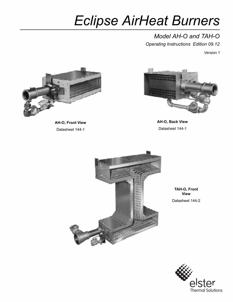
Eclipse AirHeat BurnersModel AH-O and TAH-O
Version 1
Operating Instructions Edition 09.12
AH-O, Front View
Datasheet 144-1
AH-O, Back View
Datasheet 144-1
TAH-O, Front View
Datasheet 144-2
2
CopyrightCopyright 1997 by Eclipse, inc. All rights reservedworldwide. This publication is protected by federalregulation and shall not be copied, distributed,transmitted, transcribed or translated into any human orcomputer language, in any form or by any means, to anythird parties, without the express written consent ofEclipse, inc.
Disclaimer NoticeIn accordance with the manufacturer’s policy of continualproduct improvement, the product presented in thisbrochure is subject to change without notice or obligation.
The material in this manual is believed adequate for theintended use of the product. If the product is used forpurposes other than those specified herein, confirmationof validity and suitability must be obtained. Eclipsewarrants that the product itself does not infringe upon anyUnited States patents. No further warranty is expressed orimplied.
Liability & WarrantyWe have made every effort to make this manual asaccurate and complete as possible. Should you find errorsor omissions, please bring them to our attention so that wemay correct them. In this way we hope to improve ourproduct documentation for the benefit of our customers.Please send your corrections and comments to ourTechnical Documentation Specialist.
It must be understood that Eclipse’s liability for its product,whether due to breach of warranty, negligence, strictliability, or otherwise is limited to the furnishing ofreplacement parts and Eclipse will not be liable for anyother injury, loss, damage or expenses, whether direct orconsequential, including but not limited to loss of use,
income, or damage to material arising in connection withthe sale, installation, use of, inability to use, or the repairor replacement of Eclipse’s products.
Any operation expressly prohibited in this manual, anyadjustment, or assembly procedures not recommended or authorized in these instructions shall void the warranty.
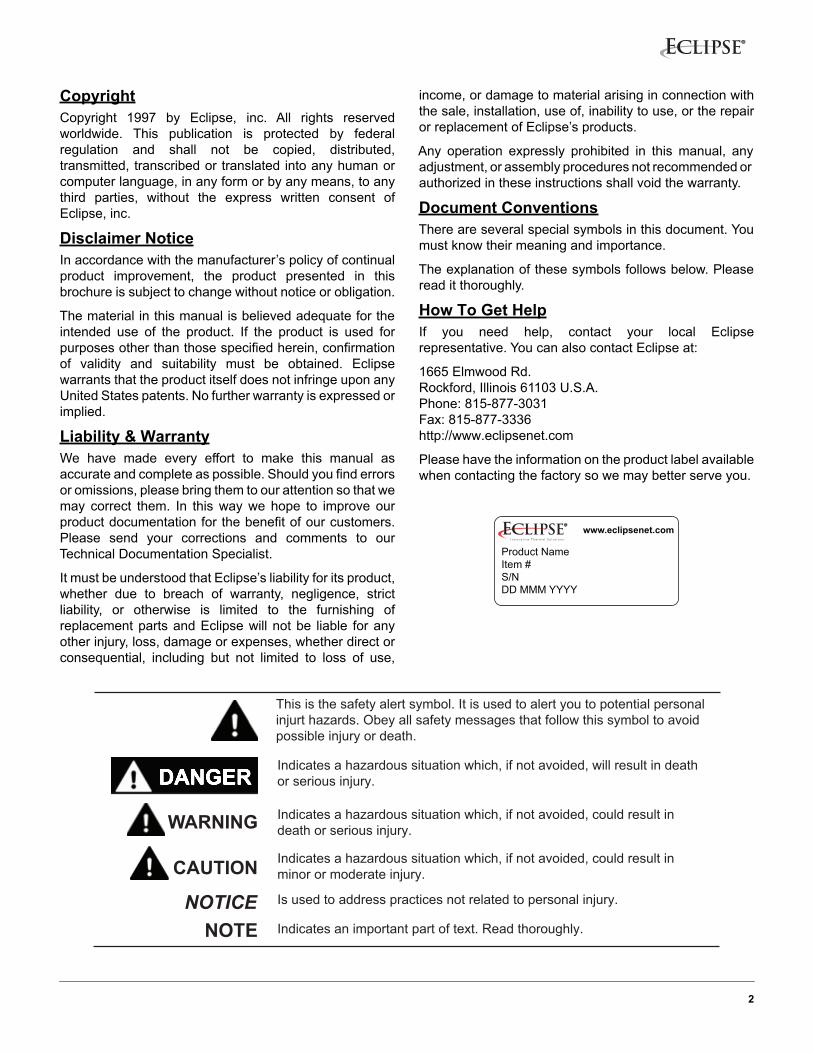
Document ConventionsThere are several special symbols in this document. Youmust know their meaning and importance.
The explanation of these symbols follows below. Pleaseread it thoroughly.
How To Get HelpIf you need help, contact your local Eclipserepresentative. You can also contact Eclipse at:
1665 Elmwood Rd.Rockford, Illinois 61103 U.S.A.Phone: 815-877-3031Fax: 815-877-3336http://www.eclipsenet.com
Please have the information on the product label availablewhen contacting the factory so we may better serve you.
Product NameItem #S/NDD MMM YYYY
www.eclipsenet.com
This is the safety alert symbol. It is used to alert you to potential personalinjurt hazards. Obey all safety messages that follow this symbol to avoidpossible injury or death.
Indicates a hazardous situation which, if not avoided, will result in deathor serious injury.
Indicates a hazardous situation which, if not avoided, could result indeath or serious injury.
Indicates a hazardous situation which, if not avoided, could result inminor or moderate injury.
Is used to address practices not related to personal injury.
Indicates an important part of text. Read thoroughly.NOTENOTICE
CAUTION
WARNING
Table of Contents
3AirHeat, V1, Operating Instructions, Edition 09.12
Safety......................................................................................................... 4
Safety Warnings ............................................................................ 4
Capabilities.................................................................................... 4
Operator Training .......................................................................... 4
Replacement Parts........................................................................ 4
Storage.......................................................................................... 4
Information Guide .................................................................................... 5
Approval of Components............................................................... 5
Burner Operating Parameters & Requirements ............................ 5
Specifications ................................................................................ 6
Control System Requirements ...................................................... 7
Duct Design and Burner Mounting ................................................ 8
Burner Firing Arrangements .......................................................... 9
Startup and Adjustment................................................................. 10
Rountine Maintenance .................................................................. 11
Troubleshooting............................................................................. 12
Appendix ................................................................................................... i
Safety
4
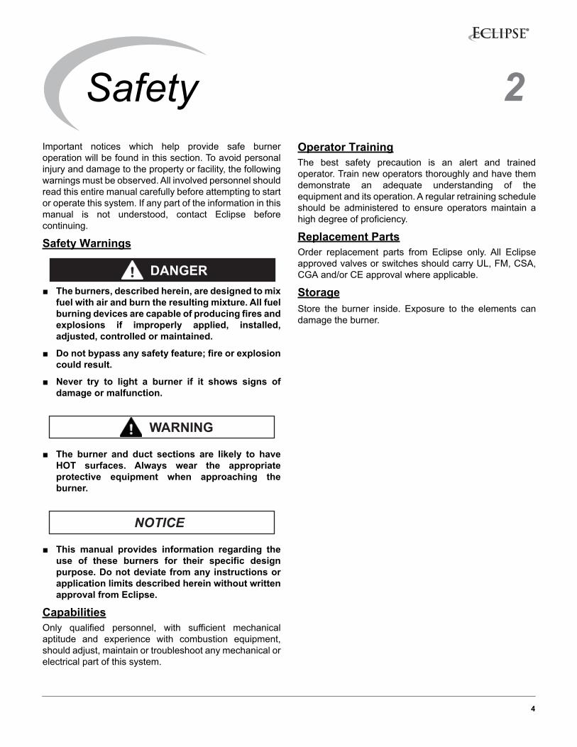
Important notices which help provide safe burneroperation will be found in this section. To avoid personalinjury and damage to the property or facility, the followingwarnings must be observed. All involved personnel shouldread this entire manual carefully before attempting to startor operate this system. If any part of the information in thismanual is not understood, contact Eclipse beforecontinuing.
Safety Warnings
■ The burners, described herein, are designed to mixfuel with air and burn the resulting mixture. All fuelburning devices are capable of producing fires andexplosions if improperly applied, installed,adjusted, controlled or maintained.
■ Do not bypass any safety feature; fire or explosioncould result.
■ Never try to light a burner if it shows signs ofdamage or malfunction.
■ The burner and duct sections are likely to haveHOT surfaces. Always wear the appropriateprotective equipment when approaching theburner.
■ This manual provides information regarding theuse of these burners for their specific designpurpose. Do not deviate from any instructions orapplication limits described herein without writtenapproval from Eclipse.
CapabilitiesOnly qualified personnel, with sufficient mechanicalaptitude and experience with combustion equipment,should adjust, maintain or troubleshoot any mechanical orelectrical part of this system.
Operator TrainingThe best safety precaution is an alert and trainedoperator. Train new operators thoroughly and have themdemonstrate an adequate understanding of theequipment and its operation. A regular retraining scheduleshould be administered to ensure operators maintain ahigh degree of proficiency.
Replacement PartsOrder replacement parts from Eclipse only. All Eclipseapproved valves or switches should carry UL, FM, CSA,CGA and/or CE approval where applicable.
StorageStore the burner inside. Exposure to the elements candamage the burner.
DANGER
WARNING
NOTICE
2
Information Guide
5AirHeat, V1, Operating Instructions, Edition 09.12
Approval of ComponentsLimit Controls & Safety EquipmentAll limit controls and safety equipment must comply withall applicable local codes and/or standards and must belisted for combustion safety by an independent testingagency. Typical application examples include:
• American: NFPA 86 with listing marks from UL, FM, CSA
• American: NFPA 86C• European: EN 746-2 with CE mark from TuV,
Gastec, Advantica
Electrical WiringAll the electrical wiring must comply with all applicablelocal codes and/or standards such as:
• NFPA Standard 70• IEC60364• CSA C22• BS7671
Gas PipingAll the gas piping must comply with all applicable localcodes and/or standards such as:
• NFPA Standard 54• ANSI Z223• EN 746-2
Where to Get the Standards:The NFPA Standards are available from: National Fire Protection Agency Batterymarch ParkQuincy, MA 02269www.nfpa.org
The ANSI Standards are available from: American National Standard Institute 1430 BroadwayNew York, NY 10018www.ansi.org
Burner Operating Parameters & RequirementsApplicationsEclipse AirHeat Burners are line type burners ideal forgenerating large volumes of clean, hot air. Applicationsinclude ovens, dryers, fume incinerators, and similarindustrial equipment.
“AH-O” and “TAH-O” models are designed for mounting inducts where all of the air required for combustion isavailable from the process airstream. Because theseburners depend on the airstream for combustion air, aprofile plate must be used to establish proper air flow pastthe burner.
Because these burners depend on the airstream forcombustion air, a profile plate must be used to establishproper air velocity past the burner. Air temperatures canbe as high as 450°F (250°C) upstream of the burner and1000°F (540°C) downstream.
Capacities & Supply PressuresSee Datasheet 144-1 and 144-2.
Burner EnvironmentWeather Protection
Protect burners from the weather.
Combustion Air
Must be free of contaminants. Eclipse stronglyrecommends use of a combustion air filter to removeairborne particles. If corrosive fumes or materials arepresent in the air, supply the blower with fresh, clean airfrom an uncontaminated area of the plant.
Room Openings
If the burner is mounted on the side of the duct, provide atleast one square inch of opening to the outdoors for every4000 Btu/hr (1.2 kW) of burner firing rate. This will admitfresh combustion air.
Access
Provide access to the burner for inspection andmaintenance.
3
6AirHeat, V1, Operating Instructions, Edition 09.12
Specifications
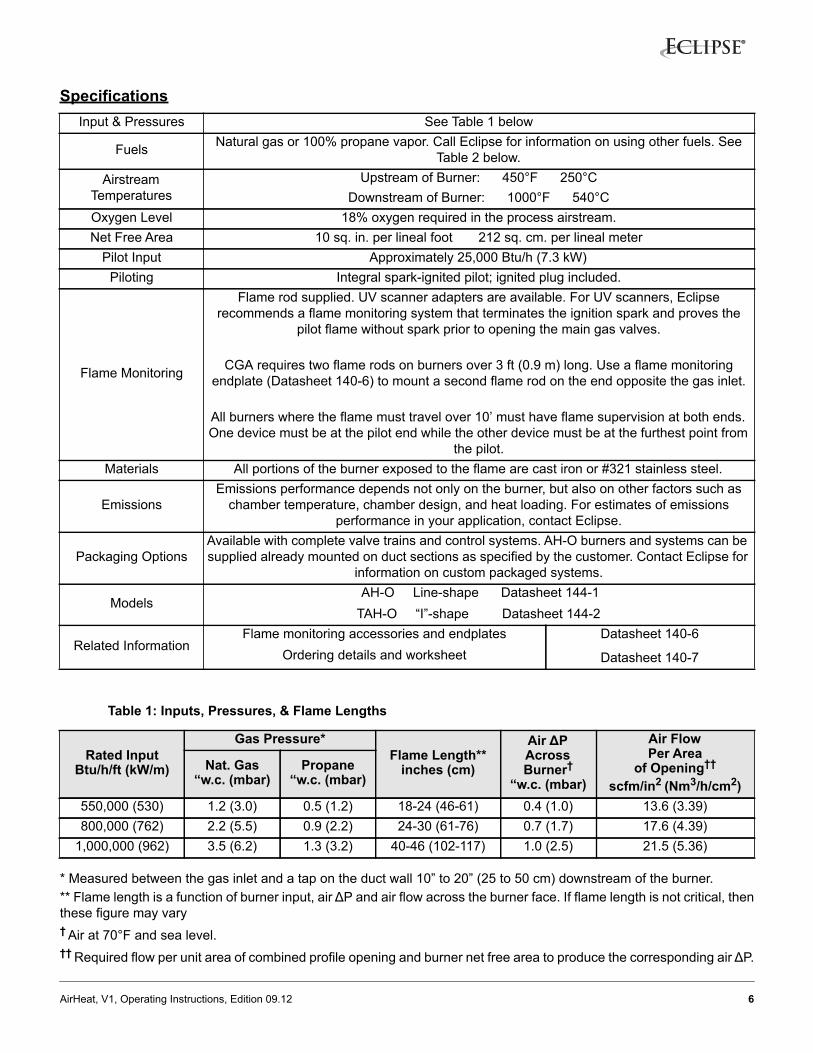
Table 1: Inputs, Pressures, & Flame Lengths
* Measured between the gas inlet and a tap on the duct wall 10” to 20” (25 to 50 cm) downstream of the burner.** Flame length is a function of burner input, air ΔP and air flow across the burner face. If flame length is not critical, thenthese figure may vary† Air at 70°F and sea level.†† Required flow per unit area of combined profile opening and burner net free area to produce the corresponding air ΔP.
Input & Pressures See Table 1 below
Fuels Natural gas or 100% propane vapor. Call Eclipse for information on using other fuels. See Table 2 below.
Airstream Temperatures
Upstream of Burner: 450°F 250°CDownstream of Burner: 1000°F 540°C
Oxygen Level 18% oxygen required in the process airstream.Net Free Area 10 sq. in. per lineal foot 212 sq. cm. per lineal meter
Pilot Input Approximately 25,000 Btu/h (7.3 kW)Piloting Integral spark-ignited pilot; ignited plug included.
Flame Monitoring
Flame rod supplied. UV scanner adapters are available. For UV scanners, Eclipse recommends a flame monitoring system that terminates the ignition spark and proves the
pilot flame without spark prior to opening the main gas valves.
CGA requires two flame rods on burners over 3 ft (0.9 m) long. Use a flame monitoring endplate (Datasheet 140-6) to mount a second flame rod on the end opposite the gas inlet.
All burners where the flame must travel over 10’ must have flame supervision at both ends. One device must be at the pilot end while the other device must be at the furthest point from
the pilot.Materials All portions of the burner exposed to the flame are cast iron or #321 stainless steel.
EmissionsEmissions performance depends not only on the burner, but also on other factors such as
chamber temperature, chamber design, and heat loading. For estimates of emissions performance in your application, contact Eclipse.
Packaging OptionsAvailable with complete valve trains and control systems. AH-O burners and systems can be supplied already mounted on duct sections as specified by the customer. Contact Eclipse for
information on custom packaged systems.
Models AH-O Line-shape Datasheet 144-1TAH-O “I”-shape Datasheet 144-2
Related InformationFlame monitoring accessories and endplates
Ordering details and worksheetDatasheet 140-6
Datasheet 140-7
Rated InputBtu/h/ft (kW/m)
Gas Pressure*Flame Length**
inches (cm)
Air ΔP Across Burner†
“w.c. (mbar)
Air FlowPer Area
of Opening††
scfm/in2 (Nm3/h/cm2)Nat. Gas
“w.c. (mbar)Propane
“w.c. (mbar)
550,000 (530) 1.2 (3.0) 0.5 (1.2) 18-24 (46-61) 0.4 (1.0) 13.6 (3.39)800,000 (762) 2.2 (5.5) 0.9 (2.2) 24-30 (61-76) 0.7 (1.7) 17.6 (4.39)
1,000,000 (962) 3.5 (6.2) 1.3 (3.2) 40-46 (102-117) 1.0 (2.5) 21.5 (5.36)
7AirHeat, V1, Operating Instructions, Edition 09.12
■ It is dangerous to use any fuel burning equipmentunless it is equipped with suitable flame sensingdevices and automatic fuel shut-off valves. Eclipsecan supply such equipment or information onalternate sources.
Control System RequirementsTurndown MethodInput is normally controlled by a motorized butterfly valveplaced in the gas line leading to the burner.
Regulator Loading LinesConnect the top diaphragm chambers of the main gas andpilot gas regulators to the duct approximately 10”(250mm) downstream of the burner. This will allow theregulators to maintain a constant supply pressure to theburner regardless of varying pressures in the duct.
PilotingPilot gas flow is adjusted shown in Figure 5.
Check ValveAt high fire, the gas pressure at the burner inlet is higherthan the air pressure, and the check valve is closed. Atlow fire, gas pressure falls below the air pressure, and thecheck valve opens, permitting a small amount of air to mixwith the gas. This premix at low fire stabilizes the flameand helps distribute the flame evenly down the length ofthe burner. See Figure 1.
Figure 1. Check Valve Operation
■ Do not install any valve or controlling device in thegas line between the burner and the check valvetee. Because this section of the gas line carries apartial premix at low fire, it is possible underunusual conditions for the flame to travel backthrough the pipe to the tee. Devices installed inthis section may be damaged and may melt,releasing gas to the atmosphere and causing firesor explosions.
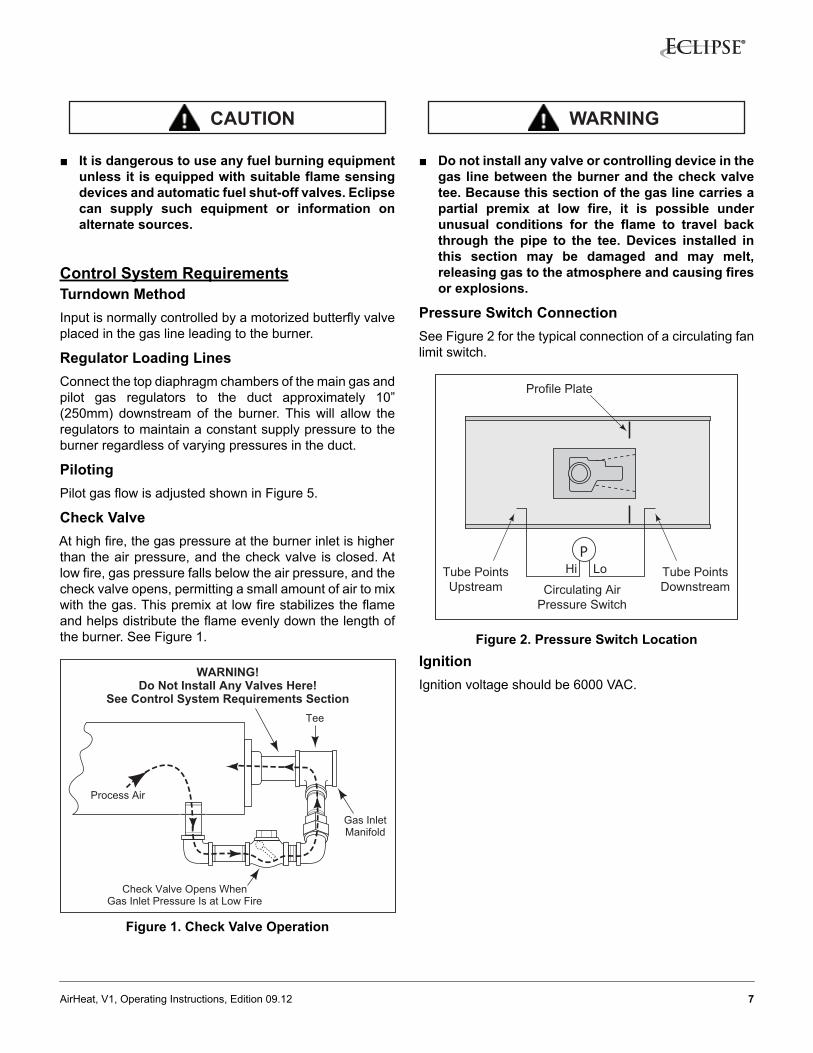
Pressure Switch ConnectionSee Figure 2 for the typical connection of a circulating fanlimit switch.
Figure 2. Pressure Switch LocationIgnitionIgnition voltage should be 6000 VAC.
CAUTION
Gas InletManifold
Check Valve Opens WhenGas Inlet Pressure Is at Low Fire
Process Air
WARNING!Do Not Install Any Valves Here!
See Control System Requirements SectionTee
WARNING
PLoHi
Circulating AirPressure Switch
Tube PointsUpstream
Tube PointsDownstream
Profile Plate
8AirHeat, V1, Operating Instructions, Edition 09.12
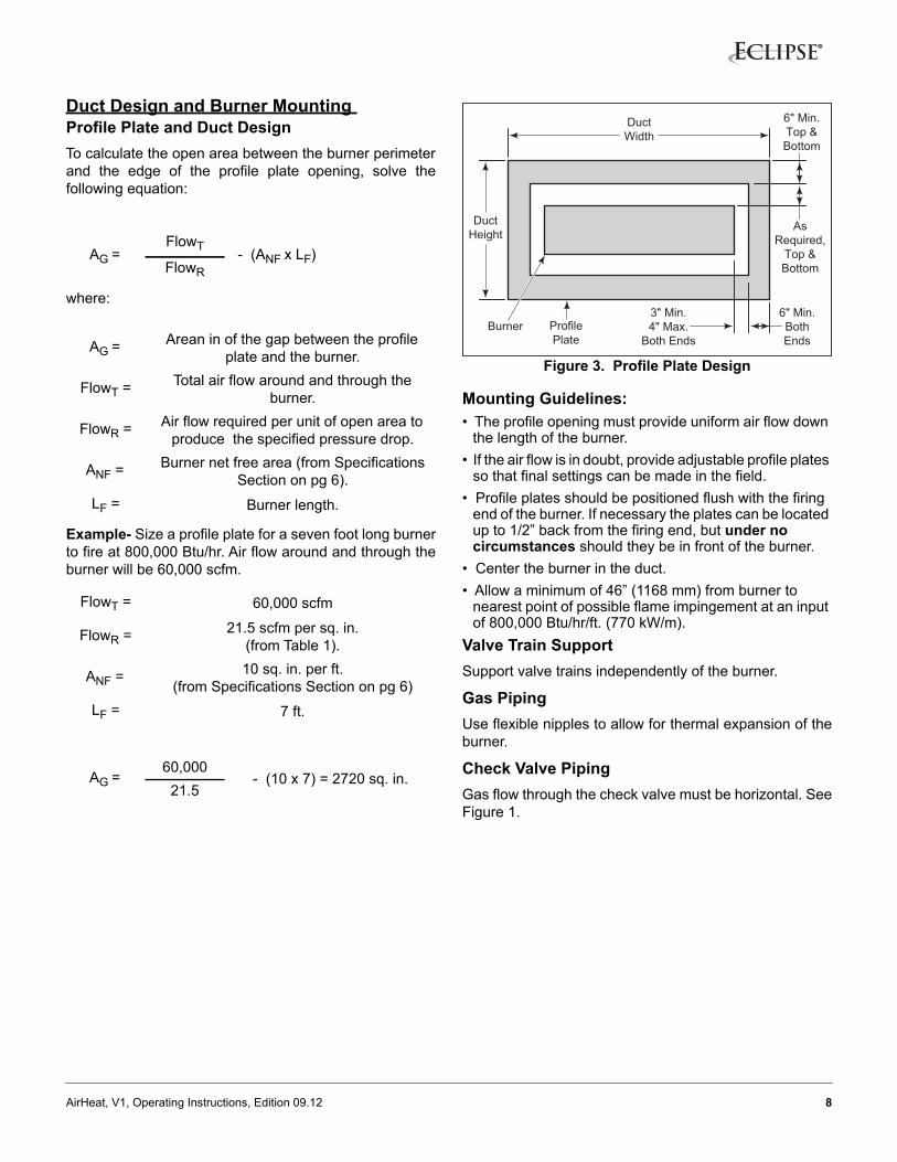
Duct Design and Burner Mounting Profile Plate and Duct Design To calculate the open area between the burner perimeterand the edge of the profile plate opening, solve thefollowing equation:
where:
Example- Size a profile plate for a seven foot long burnerto fire at 800,000 Btu/hr. Air flow around and through theburner will be 60,000 scfm.
Figure 3. Profile Plate Design
Mounting Guidelines:• The profile opening must provide uniform air flow down
the length of the burner.• If the air flow is in doubt, provide adjustable profile plates
so that final settings can be made in the field.• Profile plates should be positioned flush with the firing
end of the burner. If necessary the plates can be located up to 1/2” back from the firing end, but under no circumstances should they be in front of the burner.
• Center the burner in the duct.• Allow a minimum of 46” (1168 mm) from burner to
nearest point of possible flame impingement at an input of 800,000 Btu/hr/ft. (770 kW/m).
Valve Train SupportSupport valve trains independently of the burner.
Gas Piping Use flexible nipples to allow for thermal expansion of theburner.
Check Valve PipingGas flow through the check valve must be horizontal. SeeFigure 1.
AG = FlowT - (ANF x LF)FlowR
AG = Arean in of the gap between the profile plate and the burner.
FlowT = Total air flow around and through the burner.
FlowR = Air flow required per unit of open area to produce the specified pressure drop.
ANF = Burner net free area (from Specifications Section on pg 6).
LF = Burner length.
FlowT = 60,000 scfm
FlowR = 21.5 scfm per sq. in.(from Table 1).
ANF = 10 sq. in. per ft. (from Specifications Section on pg 6)
LF = 7 ft.
AG = 60,000
- (10 x 7) = 2720 sq. in.21.5
ProfilePlate
Burner
AsRequired,
Top &Bottom
6" Min.Top &Bottom
6" Min.BothEnds
DuctWidth
DuctHeight
3" Min.4" Max.
Both Ends
9AirHeat, V1, Operating Instructions, Edition 09.12
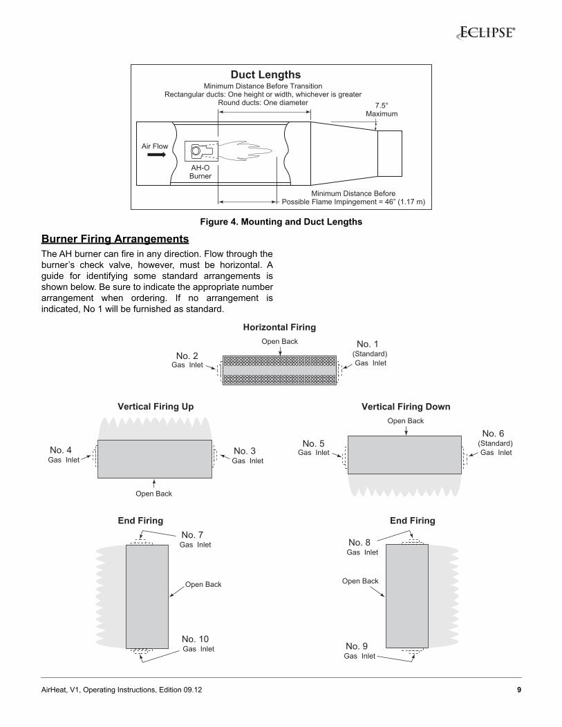
Figure 4. Mounting and Duct Lengths
Burner Firing ArrangementsThe AH burner can fire in any direction. Flow through theburner’s check valve, however, must be horizontal. Aguide for identifying some standard arrangements isshown below. Be sure to indicate the appropriate numberarrangement when ordering. If no arrangement isindicated, No 1 will be furnished as standard.
Minimum Distance BeforePossible Flame Impingement = 46” (1.17 m)
AH-OBurner
Minimum Distance Before TransitionRectangular ducts: One height or width, whichever is greater
Round ducts: One diameter 7.5°Maximum
Air Flow
Duct Lengths
Open Back No. 1(Standard)Gas Inlet
No. 2Gas Inlet
Vertical Firing Up
Open Back
No. 3Gas Inlet
No. 4Gas Inlet
End Firing End Firing
Open Back
No. 9Gas Inlet
No. 8Gas Inlet
Open Back
No. 10Gas Inlet
No. 7Gas Inlet
Horizontal Firing
Open Back
No. 6(Standard)Gas Inlet
No. 5Gas Inlet
Vertical Firing Down
10AirHeat, V1, Operating Instructions, Edition 09.12
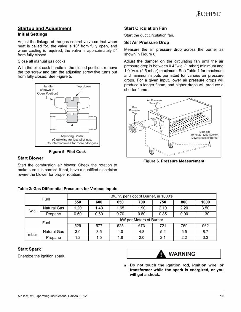
Startup and AdjustmentInitial Settings Adjust the linkage of the gas control valve so that whenheat is called for, the valve is 10° from fully open, andwhen cooling is required, the valve is approximately 5°from fully closed.Close all manual gas cocks With the pilot cock handle in the closed position, removethe top screw and turn the adjusting screw five turns outfrom fully closed. See Figure 5.
Figure 5. Pilot CockStart BlowerStart the combustion air blower. Check the rotation tomake sure it is correct. If not, have a qualified electricianrewire the blower for proper rotation.
Start Circulation Fan Start the duct circulation fan.
Set Air Pressure DropMeasure the air pressure drop across the burner asshown in Figure 6.
Adjust the damper on the circulating fan until the airpressure drop is between 0.4 ”w.c. (1 mbar) minimum and1.0 ”w.c. (2.5 mbar) maximum. See Table 1 for maximumand minimum inputs permitted for various air pressuredrops. For a given input, lower air pressure drops willproduce a longer flame, and higher drops will produce ashorter flame.
Figure 6. Pressure Measurement
Table 2: Gas Differential Pressures for Various Inputs
Start SparkEnergize the ignition spark.
■ Do not touch the ignition rod, ignition wire, ortransformer while the spark is energized, or youwill get a shock.
Top ScrewHandle(Shown in
Open Position)
Adjusting Screw(Clockwise for less pilot gas,
Counterclockwise for more pilot gas)
GasPressure
Tap
Duct Tap10" to 20" (250-500mm)Downstream of Burner
Air PressureTaps (2)
FuelBtu/hr. per Foot of Burner, in 1000’s
550 600 650 700 750 800 1000
“w.c.Natural Gas 1.20 1.40 1.65 1.90 2.10 2.20 3.50
Propane 0.50 0.60 0.70 0.80 0.85 0.90 1.30
FuelkW per Meters of Burner
529 577 625 673 721 769 962
mbarNatural Gas 3.0 3.5 4.0 4.8 5.2 5.5 8.7
Propane 1.2 1.5 1.8 2.0 2.1 2.2 3.3
WARNING
11AirHeat, V1, Operating Instructions, Edition 09.12
Set Pilot Flow Open all pilot gas valves, including the handle of the pilotcock, see Figure 5. The pilot should light.
Turn the pilot adjusting screw to produce a bushy blueflame that provides a flame monitoring signal strongenough to reliably open the gas shut-off valves.
Set Gas FlowMeasure the gas differential pressure as demonstrated inTable 2.
With the gas control valve at low fire, open all main gasvalves. The burner should light with a stable, blue low fireflame that extends evenly down the burner length.
Drive the control valve to high fire and adjust the gasadjusting valve to produce a pressure drop thatcorresponds to the desired high fire rate, as shown inTable 2.
When setting high fire, ensure the flame does not impingeon anything downstream of the burner. To shorten the
flame length for a given gas input, increase the airpressure drop as described in “Set Air Pressure Drop”paragraph above.
Check All SettingsReturn the burner to low fire and check to ensure theburner remains lit with a stable flame that extends downthe burner length. Cycle the burner between low and highfire several times, checking pressure drops and flamelengths.
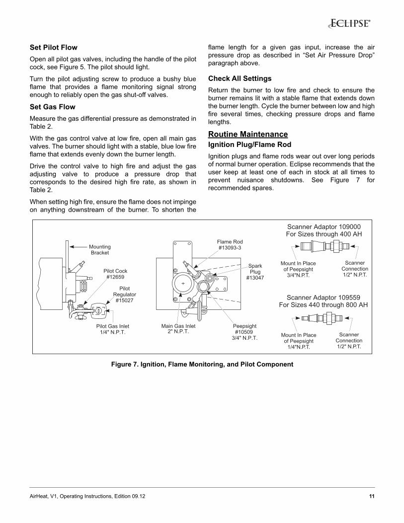
Routine MaintenanceIgnition Plug/Flame RodIgnition plugs and flame rods wear out over long periodsof normal burner operation. Eclipse recommends that theuser keep at least one of each in stock at all times toprevent nuisance shutdowns. See Figure 7 forrecommended spares.
Figure 7. Ignition, Flame Monitoring, and Pilot Component
ScannerConnection1/2" N.P.T.
Mount In Placeof Peepsight
3/4"N.P.T.
Scanner Adaptor 109559For Sizes 440 through 800 AH
Scanner Adaptor 109000For Sizes through 400 AH
Peepsight#10509
3/4" N.P.T.
Flame Rod#13093-3
SparkPlug
#13047
Main Gas Inlet2" N.P.T.
Pilot Cock#12659
PilotRegulator#15027
MountingBracket
Pilot Gas Inlet1/4" N.P.T. Scanner
Connection1/2" N.P.T.
Mount In Placeof Peepsight
1/4"N.P.T.
12AirHeat, V1, Operating Instructions, Edition 09.12
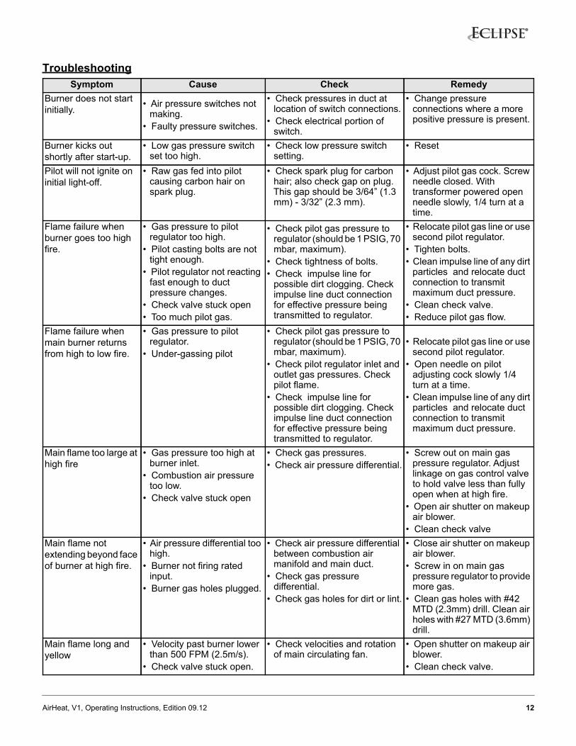
TroubleshootingSymptom Cause Check Remedy
Burner does not start initially. • Air pressure switches not
making.• Faulty pressure switches.
• Check pressures in duct at location of switch connections.
• Check electrical portion of switch.
• Change pressure connections where a more positive pressure is present.
Burner kicks out shortly after start-up.
• Low gas pressure switch set too high.
• Check low pressure switch setting.
• Reset
Pilot will not ignite on initial light-off.
• Raw gas fed into pilot causing carbon hair on spark plug.
• Check spark plug for carbon hair; also check gap on plug. This gap should be 3/64” (1.3 mm) - 3/32” (2.3 mm).
• Adjust pilot gas cock. Screw needle closed. With transformer powered open needle slowly, 1/4 turn at a time.
Flame failure when burner goes too high fire.
• Gas pressure to pilot regulator too high.
• Pilot casting bolts are not tight enough.
• Pilot regulator not reacting fast enough to duct pressure changes.
• Check valve stuck open• Too much pilot gas.
• Check pilot gas pressure to regulator (should be 1 PSIG, 70 mbar, maximum).
• Check tightness of bolts.• Check impulse line for
possible dirt clogging. Check impulse line duct connection for effective pressure being transmitted to regulator.
• Relocate pilot gas line or use second pilot regulator.
• Tighten bolts.• Clean impulse line of any dirt
particles and relocate duct connection to transmit maximum duct pressure.
• Clean check valve.• Reduce pilot gas flow.
Flame failure when main burner returns from high to low fire.
• Gas pressure to pilot regulator.
• Under-gassing pilot
• Check pilot gas pressure to regulator (should be 1 PSIG, 70 mbar, maximum).
• Check pilot regulator inlet and outlet gas pressures. Check pilot flame.
• Check impulse line for possible dirt clogging. Check impulse line duct connection for effective pressure being transmitted to regulator.
• Relocate pilot gas line or use second pilot regulator.
• Open needle on pilot adjusting cock slowly 1/4 turn at a time.
• Clean impulse line of any dirt particles and relocate duct connection to transmit maximum duct pressure.
Main flame too large at high fire
• Gas pressure too high at burner inlet.
• Combustion air pressure too low.
• Check valve stuck open
• Check gas pressures.• Check air pressure differential.
• Screw out on main gas pressure regulator. Adjust linkage on gas control valve to hold valve less than fully open when at high fire.
• Open air shutter on makeup air blower.
• Clean check valveMain flame not extending beyond face of burner at high fire.
• Air pressure differential too high.
• Burner not firing rated input.
• Burner gas holes plugged.
• Check air pressure differential between combustion air manifold and main duct.
• Check gas pressure differential.
• Check gas holes for dirt or lint.
• Close air shutter on makeup air blower.
• Screw in on main gas pressure regulator to provide more gas.
• Clean gas holes with #42 MTD (2.3mm) drill. Clean air holes with #27 MTD (3.6mm) drill.
Main flame long and yellow
• Velocity past burner lower than 500 FPM (2.5m/s).
• Check valve stuck open.
• Check velocities and rotation of main circulating fan.
• Open shutter on makeup air blower.
• Clean check valve.
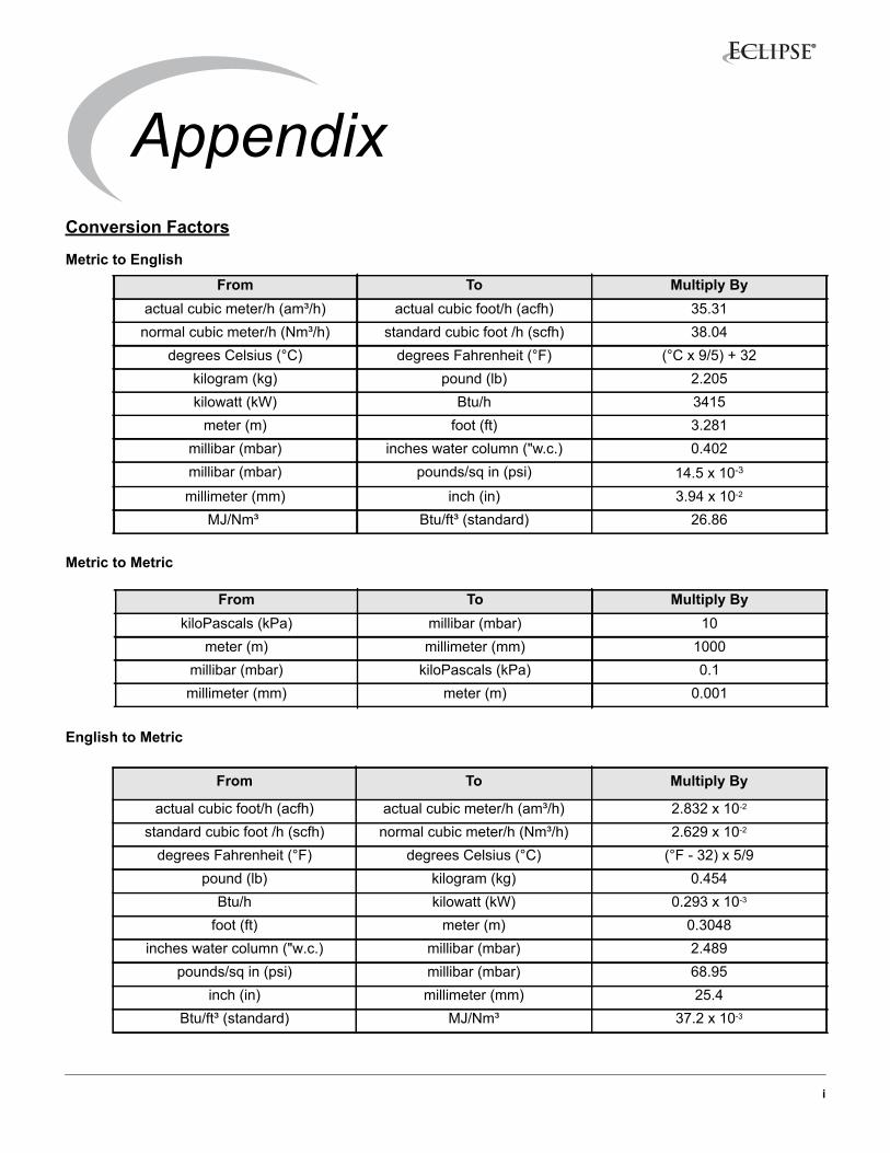
AppendixConversion Factors
Metric to English
Metric to Metric
English to Metric
From To Multiply Byactual cubic meter/h (am³/h) actual cubic foot/h (acfh) 35.31normal cubic meter/h (Nm³/h) standard cubic foot /h (scfh) 38.04
degrees Celsius (°C) degrees Fahrenheit (°F) (°C x 9/5) + 32kilogram (kg) pound (lb) 2.205kilowatt (kW) Btu/h 3415
meter (m) foot (ft) 3.281millibar (mbar) inches water column ("w.c.) 0.402millibar (mbar) pounds/sq in (psi) 14.5 x 10⁻³
millimeter (mm) inch (in) 3.94 x 10⁻²
MJ/Nm³ Btu/ft³ (standard) 26.86
From To Multiply BykiloPascals (kPa) millibar (mbar) 10
meter (m) millimeter (mm) 1000millibar (mbar) kiloPascals (kPa) 0.1millimeter (mm) meter (m) 0.001
From To Multiply By
actual cubic foot/h (acfh) actual cubic meter/h (am³/h) 2.832 x 10⁻²
standard cubic foot /h (scfh) normal cubic meter/h (Nm³/h) 2.629 x 10⁻²
degrees Fahrenheit (°F) degrees Celsius (°C) (°F - 32) x 5/9pound (lb) kilogram (kg) 0.454
Btu/h kilowatt (kW) 0.293 x 10⁻³
foot (ft) meter (m) 0.3048inches water column ("w.c.) millibar (mbar) 2.489
pounds/sq in (psi) millibar (mbar) 68.95inch (in) millimeter (mm) 25.4
Btu/ft³ (standard) MJ/Nm³ 37.2 x 10⁻³
i

© Eclipse, Inc. All Rights Reserved