eclcomfort310,applicationa333 installationguideheating.danfoss.com/pcmpdf/vigut102_a333.pdf ·...
TRANSCRIPT

Installation Guide
ECL Comfort 310, application A333
1.0 Table of Contents
1.0 Table of Contents ............................................... 11.1 Important safety and product information. . . . . . . . . . . . . . . . . . . . . 2
2.0 Installation ........................................................ 52.1 Before you start . . . . . . . . . . . . . . . . . . . . . . . . . . . . . . . . . . . . . . . . . . . . . . . . . . . . . 52.2 Identifying the system type . . . . . . . . . . . . . . . . . . . . . . . . . . . . . . . . . . . . . . 102.3 Mounting . . . . . . . . . . . . . . . . . . . . . . . . . . . . . . . . . . . . . . . . . . . . . . . . . . . . . . . . . . . 152.4 Placing the temperature sensors. . . . . . . . . . . . . . . . . . . . . . . . . . . . . . . . 182.5 Electrical connections. . . . . . . . . . . . . . . . . . . . . . . . . . . . . . . . . . . . . . . . . . . . . 202.6 Inserting the ECL Application Key . . . . . . . . . . . . . . . . . . . . . . . . . . . . . . 502.7 Check list . . . . . . . . . . . . . . . . . . . . . . . . . . . . . . . . . . . . . . . . . . . . . . . . . . . . . . . . . . . . 562.8 Navigation, ECL Application Key A333 . . . . . . . . . . . . . . . . . . . . . . . . . 57
3.0 Daily use ......................................................... 623.1 How to navigate . . . . . . . . . . . . . . . . . . . . . . . . . . . . . . . . . . . . . . . . . . . . . . . . . . . 623.2 Understanding the controller display . . . . . . . . . . . . . . . . . . . . . . . . . . 633.3 A general overview: What do the symbols mean? . . . . . . . . . . . 653.4 Monitoring temperatures and system
components . . . . . . . . . . . . . . . . . . . . . . . . . . . . . . . . . . . . . . . . . . . . . . . . . . . . . . . . 663.5 Influence overview . . . . . . . . . . . . . . . . . . . . . . . . . . . . . . . . . . . . . . . . . . . . . . . . 673.6 Manual control . . . . . . . . . . . . . . . . . . . . . . . . . . . . . . . . . . . . . . . . . . . . . . . . . . . . . 683.7 Schedule . . . . . . . . . . . . . . . . . . . . . . . . . . . . . . . . . . . . . . . . . . . . . . . . . . . . . . . . . . . . 69
4.0 Settings overview ............................................ 70
5.0 Settings, circuit 1 ............................................. 745.1 Flow temperature. . . . . . . . . . . . . . . . . . . . . . . . . . . . . . . . . . . . . . . . . . . . . . . . . . 745.2 Return limit . . . . . . . . . . . . . . . . . . . . . . . . . . . . . . . . . . . . . . . . . . . . . . . . . . . . . . . . . 765.3 Flow / power limit . . . . . . . . . . . . . . . . . . . . . . . . . . . . . . . . . . . . . . . . . . . . . . . . . 795.4 Optimization. . . . . . . . . . . . . . . . . . . . . . . . . . . . . . . . . . . . . . . . . . . . . . . . . . . . . . . . 825.5 Control parameters 1. . . . . . . . . . . . . . . . . . . . . . . . . . . . . . . . . . . . . . . . . . . . . . 865.6 Control parameters, refill pump(s) . . . . . . . . . . . . . . . . . . . . . . . . . . . . . . 915.7 Control parameters, circulation pump(s) . . . . . . . . . . . . . . . . . . . . . . 965.8 Pump control . . . . . . . . . . . . . . . . . . . . . . . . . . . . . . . . . . . . . . . . . . . . . . . . . . . . . . . 995.9 Refill water . . . . . . . . . . . . . . . . . . . . . . . . . . . . . . . . . . . . . . . . . . . . . . . . . . . . . . . . 1025.10 Refill tank. . . . . . . . . . . . . . . . . . . . . . . . . . . . . . . . . . . . . . . . . . . . . . . . . . . . . . . . . . 1095.11 Application . . . . . . . . . . . . . . . . . . . . . . . . . . . . . . . . . . . . . . . . . . . . . . . . . . . . . . . 1125.12 Water meter . . . . . . . . . . . . . . . . . . . . . . . . . . . . . . . . . . . . . . . . . . . . . . . . . . . . . . 1165.13 Flow meter . . . . . . . . . . . . . . . . . . . . . . . . . . . . . . . . . . . . . . . . . . . . . . . . . . . . . . . . 1175.14 S7, S8, S9, S10 pressure . . . . . . . . . . . . . . . . . . . . . . . . . . . . . . . . . . . . . . . . . 1205.15 Alarm . . . . . . . . . . . . . . . . . . . . . . . . . . . . . . . . . . . . . . . . . . . . . . . . . . . . . . . . . . . . . . 123
6.0 Common controller settings............................ 1286.1 Introduction to ‘Common controller settings’ . . . . . . . . . . . . . . 1286.2 Time & Date. . . . . . . . . . . . . . . . . . . . . . . . . . . . . . . . . . . . . . . . . . . . . . . . . . . . . . . 1296.3 Holiday . . . . . . . . . . . . . . . . . . . . . . . . . . . . . . . . . . . . . . . . . . . . . . . . . . . . . . . . . . . . 1306.4 Input overview . . . . . . . . . . . . . . . . . . . . . . . . . . . . . . . . . . . . . . . . . . . . . . . . . . . 1326.5 Log . . . . . . . . . . . . . . . . . . . . . . . . . . . . . . . . . . . . . . . . . . . . . . . . . . . . . . . . . . . . . . . . . 1336.6 Output override. . . . . . . . . . . . . . . . . . . . . . . . . . . . . . . . . . . . . . . . . . . . . . . . . . 1346.7 Key functions . . . . . . . . . . . . . . . . . . . . . . . . . . . . . . . . . . . . . . . . . . . . . . . . . . . . . 1356.8 System . . . . . . . . . . . . . . . . . . . . . . . . . . . . . . . . . . . . . . . . . . . . . . . . . . . . . . . . . . . . . 136
7.0 Miscellaneous................................................ 1407.1 ECA 30 / 31 setup procedures . . . . . . . . . . . . . . . . . . . . . . . . . . . . . . . . . 1407.2 Several controllers in the same system . . . . . . . . . . . . . . . . . . . . . . 1487.3 Frequently asked questions. . . . . . . . . . . . . . . . . . . . . . . . . . . . . . . . . . . . 1517.4 Definitions . . . . . . . . . . . . . . . . . . . . . . . . . . . . . . . . . . . . . . . . . . . . . . . . . . . . . . . . 153
Danfoss District Energy VI.GU.T1.02 DEN-SMT/DK 1
Installation Guide ECL Comfort 310, application A333
1.1 Important safety and product information
1.1.1 Important safety and product information
This Installation Guide is associated with ECL Application Key A333(order code no. 087H3818).
The functions are realized in ECL Comfort 310 for advancedsolutions, e.g. M-bus, Modbus and Ethernet (Internet)communication.
The application A333 complies with ECL Comfort controllers 310 asof software version 1.11 (visible at start-up of the controller and in‘Common controller settings’ in ‘System’).
The application A333 works with the Internal I/O module ECA 32(order code no. 087H3202).
Additional documentation for ECL Comfort 310, modules andaccessories is available on www.ecl.doc.danfoss.com.
Safety NoteTo avoid injury of persons and damages to the device, it is absolutelynecessary to read and observe these instructions carefully.
Necessary assembly, start-up, and maintenance work must beperformed by qualified and authorized personnel only.
Local legislations must be respected. This comprises also cabledimensions and type of isolation (double isolated at 230 V).
A fuse for the ECL Comfort installation is max. 10 A typically.
The ambient temperature range for the ECL Comfort in operation is0 - 55 °C. Exceeding this temperature range can result in malfunctions.
Installation must be avoided if there is a risk for condensation (dew).
The warning sign is used to emphasize special conditions that shouldbe taken into consideration.
This symbol indicates that this particular piece of information shouldbe read with special attention.
2 DEN-SMT/DK VI.GU.T1.02 Danfoss District Energy
Installation Guide ECL Comfort 310, application A333
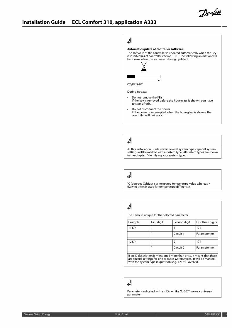
Automatic update of controller software:The software of the controller is updated automatically when the keyis inserted (as of controller version 1.11). The following animation willbe shown when the software is being updated:
Progress bar
During update:
• Do not remove the KEYIf the key is removed before the hour-glass is shown, you haveto start afresh.
• Do not disconnect the powerIf the power is interrupted when the hour-glass is shown, thecontroller will not work.
As this Installation Guide covers several system types, special systemsettings will be marked with a system type. All system types are shownin the chapter: 'Identifying your system type'.
°C (degrees Celsius) is a measured temperature value whereas K(Kelvin) often is used for temperature differences.
The ID no. is unique for the selected parameter.
Example First digit Second digit Last three digits
11174 1 1 174
- Circuit 1 Parameter no.
12174 1 2 174
- Circuit 2 Parameter no.
If an ID description is mentionedmore than once, it means that thereare special settings for one or more system types. It will be markedwith the system type in question (e.g. 12174 - A266.9).
Parameters indicated with an ID no. like "1x607" mean a universalparameter.
Danfoss District Energy VI.GU.T1.02 DEN-SMT/DK 3

Installation Guide ECL Comfort 310, application A333
Disposal NoteThis product should be dismantled and its componentssorted, if possible, in various groups before recyclingor disposal.Always follow the local disposal regulations.
4 DEN-SMT/DK VI.GU.T1.02 Danfoss District Energy

Installation Guide ECL Comfort 310, application A333
2.0 Installation
2.1 Before you start
The A333 application key contains 3 subtypes: A333.1, A333.2and A333.3 which are almost identical.
Different and extra functions are described additionally.
The application A333.1 is very flexible.
These are the basic principles:
Typically, the flow temperature is adjusted according to yourrequirements.
The flow temperature sensor S3 is the most important sensor. Thedesired flow temperature at S3 is calculated in the ECL controller,based on the outdoor temperature (S1) and the desired roomtemperature. The lower the outdoor temperature, the higher thedesired flow temperature.
By means of a week schedule (up to 3 'Comfort' periods / day), theheating circuit can be in 'Comfort' or 'Saving' mode (two differenttemperature values for the desired room temperature).
In Saving mode the heating can be reduced or switched off totally.
The motorized control valve M1 is opened gradually when the flowtemperature S3 is lower than the desired flow temperature andvice versa.
The return temperature (S5) can be limited, for example not to betoo high. If so, the desired flow temperature at S3 can be adjusted(typically to a lower value), thus resulting in a gradual closing ofthe motorized control valve. Furthermore, the return temperaturelimitation can be dependent on the outdoor temperature.Typically, the lower the outdoor temperature, the higher theaccepted return temperature.In boiler-based heating supply the return temperature should notbe too low (same adjustment procedure as above).
A connected flow or energy meter based on M-bus signal canlimit the flow or energy to a set maximum value. Furthermore thelimitation can be in relation to the outdoor temperature. Typically,the lower the outdoor temperature, the higher the accepted flow /power.
The circulation pumps P1 and P2 are operated alternately. Onecirculation pump is used as working pump and the other circulationpump is used as spare pump. The circulation pump in question isON at heat demand or at frost protection. The alternation timecan be set as a number of days and a set time on the shift day. Asolution with a single circulation pump can also be selected.
By means of the pressure difference between S9 and S10 theECL controller verifies that the circulation pump in question isoperating.
The pressure difference on the secondary side is based on the staticpressures at S9 and S10. The pressures are measured as 0 - 10 voltsignals (from pressure transmitters) and converted (scaled) in theECL controller to appropriate pressure values.
Application A333.1:
The shown diagram is a fundamental and simplified example and doesnot contain all components that are necessary in a system.
All named components are connected to the ECL Comfort controller.
List of components:
ECL 310 Electronic controller ECL Comfort 310
S1 Outdoor temperature sensor
S2 (Optional) Primary supply temperature sensor. Formonitoring purpose
S3 Secondary flow temperature sensor
S4 (Optional) Secondary return temperature sensor. Formonitoring purpose
S5 (Optional) Primary return temperature sensor
S7 (Optional) Primary supply pressure sensor. For monitoringpurpose
S8 (Optional) Primary return pressure sensor. For monitoringpurpose
S9 Secondary flow pressure sensor
S10 Secondary return pressure sensor
M1 Motorized control valve (3-point controlled)
P1/P2 Circulation pumps
P3/P4 Refill water pumps
V1 Refill water valve
V2 Pressure release valve
A1 Alarm
Danfoss District Energy VI.GU.T1.02 DEN-SMT/DK 5

Installation Guide ECL Comfort 310, application A333
If an acceptable pressure difference is not detected, the ECLcontroller activates the alarm and shifts the operating command tothe opposite circulation pump.
The heating can be switched OFF automatically when the outdoortemperature is higher than a selectable value.
The Frost protectionmodemaintains a selectable flow temperature,for example 10 °C.
In case of a too low pressure, measured by S10, the refill waterfunction will supplement with water from a water source.
A refill pump is switched ON and the ON / OFF valve V1 opens.
The refill pumps P3 and P4 are operated alternately. One pump isused as working pump and the other pump is used as spare pump.The alternation time can be set as a number of days.
A solution with a single refill pump can also be selected.
In case of a too high pressure, measured by S10, the release valveV2 (ON / OFF) will open in order to reduce the pressure.
6 DEN-SMT/DK VI.GU.T1.02 Danfoss District Energy

Installation Guide ECL Comfort 310, application A333
The application A333.2 is very flexible and works like A333.1,and with these additional features:
* The circulation pumps P1 / P2 can, as an alternative to ON-OFFcontrol, be speed controlled by means of a 0 - 10 volt signal.The desired pressure difference between S9 and S10 is set forthe speed control procedure.A flow-meter F2 (pulse signal, analogue signal S13 or M-Bus)measures the circulation of water in the heating circuit.
* The level in the refill water storage tank is measured bymeans of the pressure sensor S12. When a too low pressureis measured, the ON / OFF valve V3 opens. An acceptablepressure will close the V3 valve.
* The refill water pumps P3 / P4 can, as an alternative to ON-OFFcontrol, be speed controlled by means of a 0 - 10 volt signal.The desired pressure at S10 is set for the speed controlprocedure.A flow-meter F1 (pulse signal or M-Bus) measures the injectedrefill water.
Application A333.2:
The shown diagram is a fundamental and simplified example and doesnot contain all components that are necessary in a system.
All named components are connected to the ECL Comfort controller.
List of components:
ECL 310 Electronic controller ECL Comfort 310
ECA 32 Built-in extension module
S1 Outdoor temperature sensor
S2 (Optional) Primary supply temperature sensor. Formonitoring purpose
S3 Secondary flow temperature sensor
S4 (Optional) Secondary return temperature sensor. Formonitoring purpose
S5 (Optional) Primary return temperature sensor
S7 (Optional) Primary supply pressure sensor. For monitoringpurpose
S8 (Optional) Primary return pressure sensor. For monitoringpurpose
S9 Secondary flow pressure sensor
S10 Secondary return pressure sensor
F1 (Optional) Flowmeter (pulse or M-bus signal)
F2 (Optional) Flowmeter (pulse, 0 - 10 volt or M-bus signal)
M1 Motorized control valve (3-point controlled)
M2 Speed control (0 - 10 volt) of P3 / P4
M3 Speed control (0 - 10 volt) of P1 / P2
P1/P2 Circulation pumps
P3/P4 Refill water pumps
V1 Refill water valve
V2 Pressure release valve
V3 Refill water tank valve
A1 Alarm
Danfoss District Energy VI.GU.T1.02 DEN-SMT/DK 7

Installation Guide ECL Comfort 310, application A333
The application A333.3 is very flexible and works like A333.2,but with this feature:
* The motorized control valve M1 is controlled by means of a0 - 10 volt signal.
Application A333.2:
The shown diagram is a fundamental and simplified example and doesnot contain all components that are necessary in a system.
All named components are connected to the ECL Comfort controller.
List of components:
ECL 310 Electronic controller ECL Comfort 310
ECA 32 Built-in extension module
S1 Outdoor temperature sensor
S2 (Optional) Primary supply temperature sensor. Formonitoring purpose
S3 Secondary flow temperature sensor
S4 (Optional) Secondary return temperature sensor. Formonitoring purpose
S5 (Optional) Primary return temperature sensor
S7 (Optional) Primary supply pressure sensor. For monitoringpurpose
S8 (Optional) Primary return pressure sensor. For monitoringpurpose
S9 Secondary flow pressure sensor
S10 Secondary return pressure sensor
F1 (Optional) Flowmeter (pulse or M-bus signal)
F2 (Optional) Flowmeter (pulse, 0 - 10 volt or M-bus signal)
M1 Motorized control valve (0 - 10 volt controlled)
M2 Speed control (0 - 10 volt) of P3 / P4
M3 Speed control (0 - 10 volt) of P1 / P2
P1/P2 Circulation pumps
P3/P4 Refill water pumps
V1 Refill water valve
V2 Pressure release valve
V3 Refill water tank valve
A1 Alarm
8 DEN-SMT/DK VI.GU.T1.02 Danfoss District Energy

Installation Guide ECL Comfort 310, application A333
Application A333 in general:
Up to two Remote Control Units, the ECA 30 can be connected toone ECL controller in order to control the ECL controller remotely.
Exercise of circulation pumps and control valve in periods withoutheating demand can be arranged.
Additional ECL Comfort controllers can be connected via the ECL485 bus in order to utilize common outdoor temperature signal,time and date signals. The ECL Controllers in the ECL 485 systemcan work in master - slave system.
A connected flow or energy meter (based on M-bus signal) canlimit the flow or energy to a set maximum and in relation to theoutdoor temperature.
Unused input can, by means of an override switch, be used tooverride the schedule to a fixed 'Comfort' or 'Saving' mode.
Modbus communication to a SCADA system can be established.The M-bus data can furthermore be transferred to the Modbuscommunication.
Alarm A1 (= relay 6) can be activated:
• if the actual flow temperature differs from the desired flowtemperature.
• if a temperature sensor or its connection disconnects / shortcircuits. (See: Common controller settings > System > Rawinput overview).
• if the circulation pump(s) do(es) not generate acceptablepressure.
• if the refill water pump(s) do(es) not generate acceptablepressure.
• if measured pressures are not inside an acceptable pressurerange.
The controller is pre-programmed with factory settings that are shownin the relevant chapters of this guide.
Danfoss District Energy VI.GU.T1.02 DEN-SMT/DK 9

Installation Guide ECL Comfort 310, application A333
2.2 Identifying the system type
Sketch your application
The ECL Comfort controller series is designed for a wide rangeof heating, domestic hot-water (DHW) and cooling systems withdifferent configurations and capacities. If your system differsfrom the diagrams shown here, you may want to make a sketchof the system about to be installed. This makes it easier to usethe Installation Guide, which will guide you step-by-step frominstallation to final adjustments before the end-user takes over.
The ECL Comfort controller is a universal controller that can beused for various systems. Based on the shown standard systems,it is possible to configure additional systems. In this chapter youfind the most frequently used systems. If your system is not quiteas shown below, find the diagram which has the best resemblancewith your system and make your own combinations.
The circulation pump(s) in heating circuit(s) can be placed in the flowas well as the return. Place the pump according to the manufacturer’sspecification.
10 DEN-SMT/DK VI.GU.T1.02 Danfoss District Energy

Installation Guide ECL Comfort 310, application A333
A333.1, ex. aHeating system with control of up to 2 circulation pumps and up to 2 refill water pumps
A333.1, ex. bBasic heating system
Danfoss District Energy VI.GU.T1.02 DEN-SMT/DK 11

Installation Guide ECL Comfort 310, application A333
A333.1, ex. cHeating system with circulation pump feedback
A333.1, ex. dHeating system with refill water system
12 DEN-SMT/DK VI.GU.T1.02 Danfoss District Energy

Installation Guide ECL Comfort 310, application A333
A333.1, ex. eHeating system with refill water and excess pressure system
A333.2, ex. aHeating system with ON / OFF and speed control of up to 2 circulation pumps and up to 2 refill water pumps. Refill water storage control.
Danfoss District Energy VI.GU.T1.02 DEN-SMT/DK 13
Installation Guide ECL Comfort 310, application A333
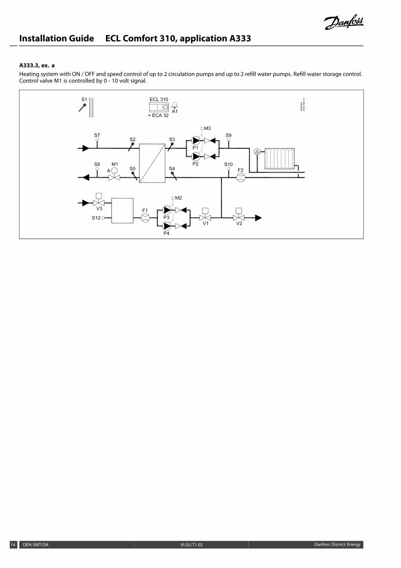
A333.3, ex. aHeating system with ON / OFF and speed control of up to 2 circulation pumps and up to 2 refill water pumps. Refill water storage control.Control valve M1 is controlled by 0 - 10 volt signal.
14 DEN-SMT/DK VI.GU.T1.02 Danfoss District Energy
Installation Guide ECL Comfort 310, application A333
2.3 Mounting
2.3.1 Mounting the ECL Comfort controller
For easy access, you should mount the ECL Comfort controller nearthe system. Select one of the following methods using the samebase part (code no. 087H3230):
• Mounting on a wall
• Mounting on a DIN rail (35 mm)
The ECL Comfort 310 can only be mounted in the ECL Comfort310 base part.
Screws, PG cable glands and rawlplugs are not supplied.
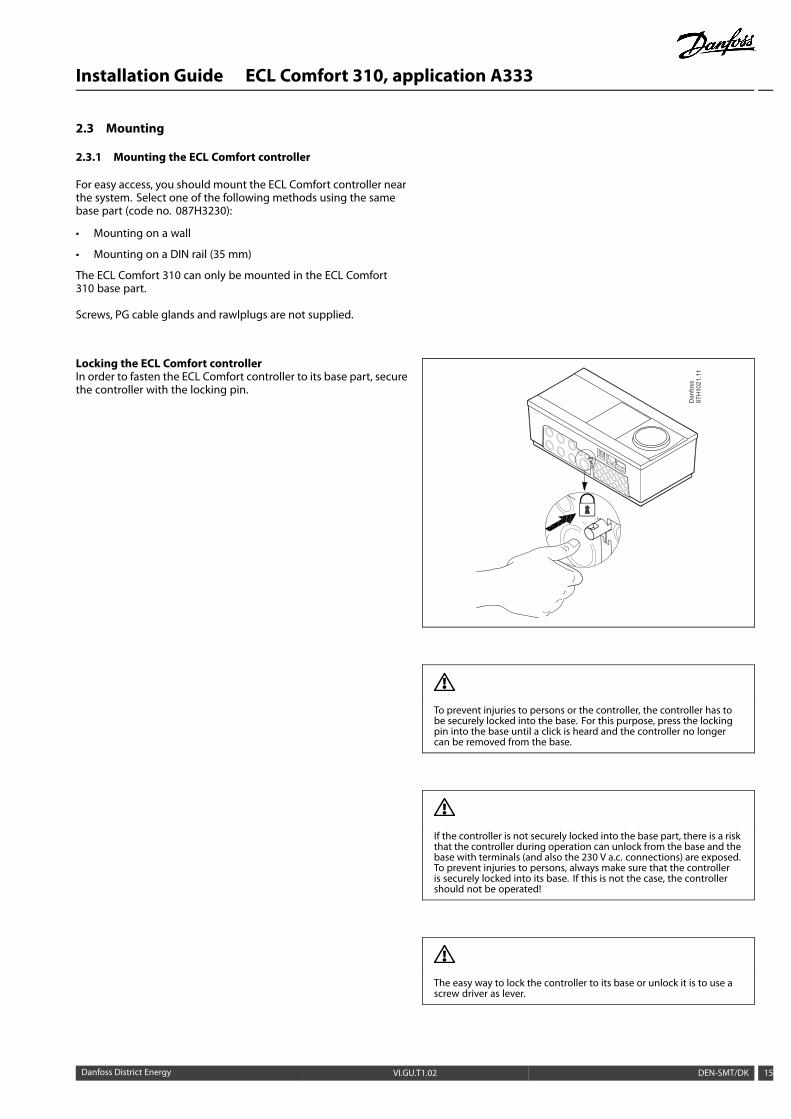
Locking the ECL Comfort controllerIn order to fasten the ECL Comfort controller to its base part, securethe controller with the locking pin.
To prevent injuries to persons or the controller, the controller has tobe securely locked into the base. For this purpose, press the lockingpin into the base until a click is heard and the controller no longercan be removed from the base.
If the controller is not securely locked into the base part, there is a riskthat the controller during operation can unlock from the base and thebase with terminals (and also the 230 V a.c. connections) are exposed.To prevent injuries to persons, always make sure that the controlleris securely locked into its base. If this is not the case, the controllershould not be operated!
The easy way to lock the controller to its base or unlock it is to use ascrew driver as lever.
Danfoss District Energy VI.GU.T1.02 DEN-SMT/DK 15

Installation Guide ECL Comfort 310, application A333
Mounting on a wallMount the base part on a wall with a smooth surface. Establish theelectrical connections and position the controller in the base part.Secure the controller with the locking pin.
Mounting on a DIN rail (35 mm)Mount the base part on a DIN rail. Establish the electricalconnections and position the controller in the base part. Securethe controller with the locking pin.
Dismounting the ECL Comfort controllerIn order to remove the controller from the base part, pull out thelocking pin by means of a screwdriver. The controller can now beremoved from the base part.
The easy way to lock the controller to its base or unlock it is to use ascrew driver as lever.
Before removing the ECL Comfort controller from the base part, ensurethat the supply voltage is disconnected.
16 DEN-SMT/DK VI.GU.T1.02 Danfoss District Energy
Installation Guide ECL Comfort 310, application A333
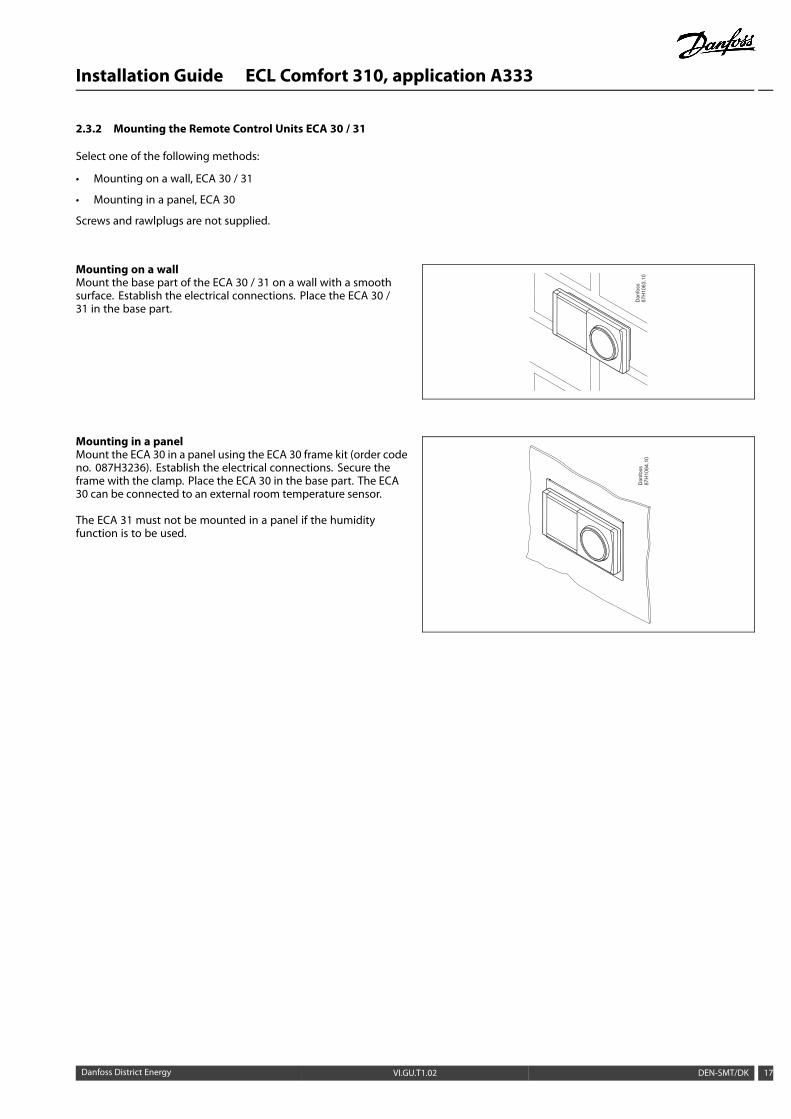
2.3.2 Mounting the Remote Control Units ECA 30 / 31
Select one of the following methods:
• Mounting on a wall, ECA 30 / 31
• Mounting in a panel, ECA 30
Screws and rawlplugs are not supplied.
Mounting on a wallMount the base part of the ECA 30 / 31 on a wall with a smoothsurface. Establish the electrical connections. Place the ECA 30 /31 in the base part.
Mounting in a panelMount the ECA 30 in a panel using the ECA 30 frame kit (order codeno. 087H3236). Establish the electrical connections. Secure theframe with the clamp. Place the ECA 30 in the base part. The ECA30 can be connected to an external room temperature sensor.
The ECA 31 must not be mounted in a panel if the humidityfunction is to be used.
Danfoss District Energy VI.GU.T1.02 DEN-SMT/DK 17

Installation Guide ECL Comfort 310, application A333
2.4 Placing the temperature sensors
2.4.1 Placing the temperature sensors
It is important that the sensors are mounted in the correct positionin your system.
The temperature sensor mentioned below are sensors used forthe ECL Comfort 210 and 310 series which not all will be neededfor your application!
Outdoor temperature sensor (ESMT)The outdoor sensor should bemounted on that side of the buildingwhere it is less likely to be exposed to direct sunshine. It should notbe placed close to doors, windows or air outlets.
Flow temperature sensor (ESMU, ESM-11 or ESMC)Place the sensor max. 15 cm from the mixing point. In systemswith heat exchanger, Danfoss recommends that the ESMU-type tobe inserted into the exchanger flow outlet.
Make sure that the surface of the pipe is clean and even wherethe sensor is mounted.
Return temperature sensor (ESMU, ESM-11 or ESMC)The return temperature sensor should always be placed so that itmeasures a representative return temperature.
Room temperature sensor(ESM-10, ECA 30 / 31 Remote Control Unit)
Place the room sensor in the room where the temperature is to becontrolled. Do not place it on outside walls or close to radiators,windows or doors.
Boiler temperature sensor (ESMU, ESM-11 or ESMC)Place the sensor according to the boiler manufacturer’sspecification.
Air duct temperature sensor (ESMB-12 or ESMU types)Place the sensor so that it measures a representative temperature.
DHW temperature sensor (ESMU or ESMB-12)Place the DHW temperature sensor according to themanufacturer’sspecification.
Slab temperature sensor (ESMB-12)Place the sensor in a protection tube in the slab.
ESM-11: Do not move the sensor after it has been fastened in order toavoid damage to the sensor element.
ESM-11, ESMC and ESMB-12: Use heat conducting paste for quickmeasurement of the temperature.
ESMU and ESMB-12: Using a sensor pocket to protect the sensor will,however, result in a slower temperature measurement.
18 DEN-SMT/DK VI.GU.T1.02 Danfoss District Energy

Installation Guide ECL Comfort 310, application A333
Pt 1000 temperature sensor (IEC 751B, 1000 Ω / 0 °C) Relationship between temperature and ohmic value:
-50
800
900
1000
1100
1200
1300
1400
1500
1600
-25 0 25 50 75 100 125 150°C
Ω
Ω
803843 882922961
1000103910781117115511941232127113091347138514231461149815351573
°C
-50 -40 -30-20-10 0102030405060708090
100110120130140150
Danfoss District Energy VI.GU.T1.02 DEN-SMT/DK 19

Installation Guide ECL Comfort 310, application A333
2.5 Electrical connections
2.5.1 Electrical connections 230 V a.c. in general
The common ground terminal is used for connection of relevantcomponents (pumps, motorized control valves).
20 DEN-SMT/DK VI.GU.T1.02 Danfoss District Energy
Installation Guide ECL Comfort 310, application A333
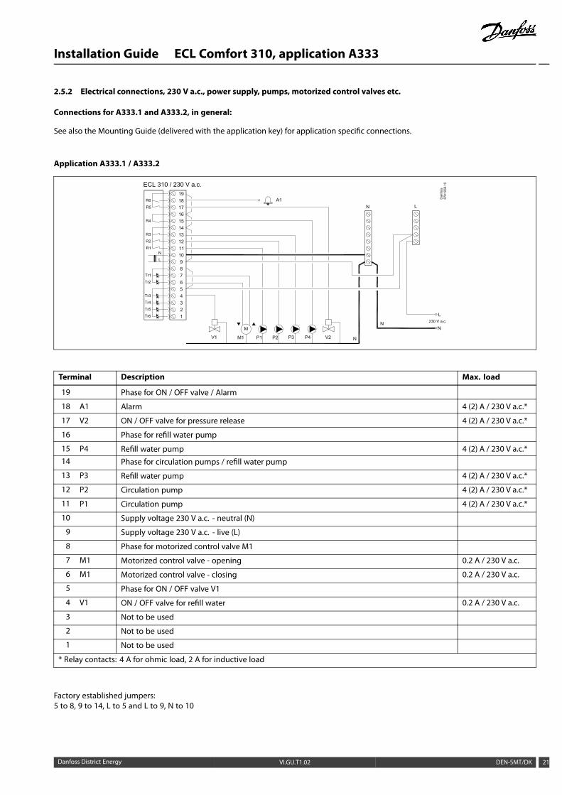
2.5.2 Electrical connections, 230 V a.c., power supply, pumps, motorized control valves etc.
Connections for A333.1 and A333.2, in general:
See also the Mounting Guide (delivered with the application key) for application specific connections.
Application A333.1 / A333.2
Terminal Description Max. load
19 Phase for ON / OFF valve / Alarm
18 A1 Alarm 4 (2) A / 230 V a.c.*
17 V2 ON / OFF valve for pressure release 4 (2) A / 230 V a.c.*
16 Phase for refill water pump
15 P4 Refill water pump 4 (2) A / 230 V a.c.*14 Phase for circulation pumps / refill water pump
13 P3 Refill water pump 4 (2) A / 230 V a.c.*
12 P2 Circulation pump 4 (2) A / 230 V a.c.*
11 P1 Circulation pump 4 (2) A / 230 V a.c.*
10 Supply voltage 230 V a.c. - neutral (N)
9 Supply voltage 230 V a.c. - live (L)
8 Phase for motorized control valve M1
7 M1 Motorized control valve - opening 0.2 A / 230 V a.c.
6 M1 Motorized control valve - closing 0.2 A / 230 V a.c.
5 Phase for ON / OFF valve V1
4 V1 ON / OFF valve for refill water 0.2 A / 230 V a.c.
3 Not to be used
2 Not to be used
1 Not to be used
* Relay contacts: 4 A for ohmic load, 2 A for inductive load
Factory established jumpers:5 to 8, 9 to 14, L to 5 and L to 9, N to 10
Danfoss District Energy VI.GU.T1.02 DEN-SMT/DK 21

Installation Guide ECL Comfort 310, application A333
Wire cross section: 0.5 - 1.5 mm²Incorrect connection can damage the electronic outputs.Max. 2 x 1.5 mm² wires can be inserted into each screw terminal.
22 DEN-SMT/DK VI.GU.T1.02 Danfoss District Energy

Installation Guide ECL Comfort 310, application A333
2.5.3 Electrical connections, 230 V a.c., power supply, pumps, motorized control valves etc.
Connections for A333.3, in general:
See also the Mounting Guide (delivered with the application key) for application specific connections.
Application A333.3
Terminal Description Max. load
19 Phase for ON / OFF valve / Alarm
18 A1 Alarm 4 (2) A / 230 V a.c.*
17 V2 ON / OFF valve for pressure release 4 (2) A / 230 V a.c.*
16 Phase for refill water pump
15 P4 Refill water pump 4 (2) A / 230 V a.c.*14 Phase for circulation pumps / refill water pump
13 P3 Refill water pump 4 (2) A / 230 V a.c.*
12 P2 Circulation pump 4 (2) A / 230 V a.c.*
11 P1 Circulation pump 4 (2) A / 230 V a.c.*
10 Supply voltage 230 V a.c. - neutral (N)
9 Supply voltage 230 V a.c. - live (L)
8 Not to be used
7 Not to be used
6 Not to be used
5 Phase for ON / OFF valve V1
4 V1 ON / OFF valve for refill water 0.2 A / 230 V a.c.
3 Not to be used 0.2 A / 230 V a.c.
2 Not to be used 0.2 A / 230 V a.c.
1 Not to be used 0.2 A / 230 V a.c.
* Relay contacts: 4 A for ohmic load, 2 A for inductive load
Factory established jumpers:5 to 8, 9 to 14, L to 5 and L to 9, N to 10
Danfoss District Energy VI.GU.T1.02 DEN-SMT/DK 23

Installation Guide ECL Comfort 310, application A333
Wire cross section: 0.5 - 1.5 mm²Incorrect connection can damage the electronic outputs.Max. 2 x 1.5 mm² wires can be inserted into each screw terminal.
24 DEN-SMT/DK VI.GU.T1.02 Danfoss District Energy

Installation Guide ECL Comfort 310, application A333
2.5.4 Electrical connections, ECA 32
Connections for A333.2 and A333.3, in general:
See also the Mounting Guide (delivered with the application key) for application specific connections.
Terminal Description Max. load
39 R10 Relay 10, not used 4 (2) A / 230 V a.c.*
40 R10
41 R9 Relay 9, not used 4 (2) A / 230 V a.c.*
42 R9
43 R8 Relay 8, not used 4 (2) A / 230 V a.c.*44 R8
45 R8 4 (2) A / 230 V a.c.*
46 R7 Relay 7
47 R7 V3, ON / OFF valve for pressure release
48 R7 Phase for ON / OFF valve V3
49 Common terminal for input signals
50 S11 Input: Position signal from M1, 0 - 10 volt
51 S12 Input: Refill water level in storage tank, 0 - 10 volt
52 S13 Input: F2 flow signal, 0 - 10 volt
53 Not to be used
54 Not to be used
55 Not to be used
56 Reference terminal for Analogue out 2 (M2) and 3 (M3)
57 F1 Input: Flow-meter, pulse type
58 F2 Input: Flow-meter, pulse type
59 M1 Analogue out 1: 0 - 10 volt for control of motorized control valve M1 (A333.3) 2 mA **
60 M2 Analogue out 2: 0 - 10 volt for speed control of refill water pumps P3 and P4 (A333.2, A333.3) 2 mA **
61 M3 Analogue out 3: 0 - 10 volt for speed control of circulation pumps P1 and P2 (A333.2, A333.3) 2 mA **
62 Reference terminal for Analogue out 1 (M1)
* Relay contacts: 4 A for ohmic load, 2 A for inductive load
** Min. resistance: 5 KΩ
Danfoss District Energy VI.GU.T1.02 DEN-SMT/DK 25

Installation Guide ECL Comfort 310, application A333
2.5.5 Electrical connections, ON / OFF valve V3 controlled from relay output in ECA 32
Connections for A333.2 and A333.3, in general:See also the Mounting Guide (delivered with the application key) for application specific connections.
Application A333.2 / A333.3
2.5.6 Electrical connections, 230 V a.c., power supply, motorized control valve M1 controlled by 0 - 10 volt from ECA 32
Connections for A333.3, in general:See also the Mounting Guide (delivered with the application key) for application specific connections.
Application A333.3
The transformer for supplying the actuator must be a double-isolated version.
26 DEN-SMT/DK VI.GU.T1.02 Danfoss District Energy

Installation Guide ECL Comfort 310, application A333
2.5.7 Electrical connections, 230 V a.c., power supply, control of 2 or 3 phase powered pumps
Connections for A333.1, in general:See also the Mounting Guide (delivered with the application key) for application specific connections.
Application A333.1
2.5.8 Electrical connections, 230 V a.c., power supply, ON / OFF control and speed control of 1 phase powered pumps
Connections for A333.2 and A333.3, in general:See also the Mounting Guide (delivered with the application key) for application specific connections.
Application A333.2 / A333.3
Danfoss District Energy VI.GU.T1.02 DEN-SMT/DK 27

Installation Guide ECL Comfort 310, application A333
2.5.9 Electrical connections, 230 V a.c., power supply, 0 - 10 volt for speed control of 1 phase powered pumps
Connections for A333.2 and A333.3, in general:See also the Mounting Guide (delivered with the application key) for application specific connections.
Application A333.2 / A333.3
2.5.10 Electrical connections, 230 V a.c., power supply, ON / OFF control and speed control of 2 or 3 phase powered pumps
Connections for A333.2 and A333.3, in general:See also the Mounting Guide (delivered with the application key) for application specific connections.
Application A333.2 / A333.3
28 DEN-SMT/DK VI.GU.T1.02 Danfoss District Energy

Installation Guide ECL Comfort 310, application A333
2.5.11 Electrical connections, 230 V a.c., power supply, ON / OFF control and speed control (via Frequency Converter) of 1phase powered pumps
Connections for A333.2 and A333.3, in general:See also the Mounting Guide (delivered with the application key) for application specific connections.
Application A333.2 / A333.3
FC = Frequency Converter
2.5.12 Electrical connections, 230 V a.c., power supply, ON / OFF control and speed control (via Frequency Converter) of 2or 3 phase powered pumps
Connections for A333.2 and A333.3, in general:See also the Mounting Guide (delivered with the application key) for application specific connections.
Application A333.2 / A333.3
FC = Frequency Converter
Danfoss District Energy VI.GU.T1.02 DEN-SMT/DK 29

Installation Guide ECL Comfort 310, application A333
2.5.13 Electrical connections, example with external Start / Stop control of a Frequency Converter for circulation pumps P1 / P2
Application A333.2 / A333.3
FC = Frequency Converter
2.5.14 Electrical connections, example with external Start / Stop control of a Frequency Converter for refill water pumps P3 / P4
Application A333.2 / A333.3
FC = Frequency Converter
30 DEN-SMT/DK VI.GU.T1.02 Danfoss District Energy

Installation Guide ECL Comfort 310, application A333
2.5.15 Electrical connections, safety thermostats, 230 V a.c. or 24 V a.c.
With safety thermostat, 1–step closing:Motorized control valve without safety function
Dan
foss
87H
2105
.10ECL 210 / 310
M1
With safety thermostat, 1–step closing:Motorized control valve with safety function
Dan
foss
87H
2107
.10ECL 210 / 310
M1
With safety thermostat, 2–step closing:Motorized control valve with safety function
ECL 210 / 310
Dan
foss
87H
2109
.10
M1
Danfoss District Energy VI.GU.T1.02 DEN-SMT/DK 31
Installation Guide ECL Comfort 310, application A333
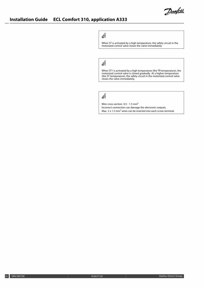
When ST is activated by a high temperature, the safety circuit in themotorized control valve closes the valve immediately.
When ST1 is activated by a high temperature (the TR temperature), themotorized control valve is closed gradually. At a higher temperature(the ST temperature), the safety circuit in the motorized control valvecloses the valve immediately.
Wire cross section: 0.5 - 1.5 mm²Incorrect connection can damage the electronic outputs.Max. 2 x 1.5 mm² wires can be inserted into each screw terminal.
32 DEN-SMT/DK VI.GU.T1.02 Danfoss District Energy

Installation Guide ECL Comfort 310, application A333
2.5.16 Electrical connections, 24 V a.c. (ECL 310 only), power supply, pumps, motorized valves etc.
Connections for A333.1 and A333.2, in general:
See also the Mounting Guide (delivered with the application key) for application specific connections.
Application A333.1 / A333.2
Terminal Description Max. load
19 Supply voltage (SP) for ON / OFF valve / Alarm
18 A1 Alarm 4 (2) A / 24 V a.c.*
17 V2 ON / OFF valve for pressure release 4 (2) A / 24 V a.c.*
16 Supply voltage (SP) for refill water pump
15 P4 Refill water pump 4 (2) A / 24 V a.c.*14 Supply voltage (SP) for circulation pumps / refill water pump
13 P3 Refill water pump 4 (2) A / 24 V a.c.*
12 P2 Circulation pump 4 (2) A / 24 V a.c.*
11 P1 Circulation pump 4 (2) A / 24 V a.c.*
10 Supply voltage 24 V a.c. - (SN)
9 Supply voltage 24 V a.c. - (SP)
8 Supply voltage (SP) for motorized control valve M1
7 M1 Motorized control valve - opening 1 A / 24 V a.c.
6 M1 Motorized control valve - closing 1 A / 24 V a.c.
5 Supply voltage (SP) for ON / OFF valve V1
4 V1 ON / OFF valve for refill water 1 A / 24 V a.c.
3 Not to be used
2 Not to be used
1 Not to be used
* Relay contacts: 4 A for ohmic load, 2 A for inductive load
Factory established jumpers:5 to 8, 9 to 14, L to 5 and L to 9, N to 10
Danfoss District Energy VI.GU.T1.02 DEN-SMT/DK 33

Installation Guide ECL Comfort 310, application A333
Wire cross section: 0.5 - 1.5 mm²Incorrect connection can damage the electronic outputs.Max. 2 x 1.5 mm² wires can be inserted into each screw terminal.
Do not connect 230 V a.c. powered components to a 24 V a.c. powersupplied controller directly. Use auxilliary relays (K) to separate 230V a.c. from 24 V a.c.
34 DEN-SMT/DK VI.GU.T1.02 Danfoss District Energy
Installation Guide ECL Comfort 310, application A333
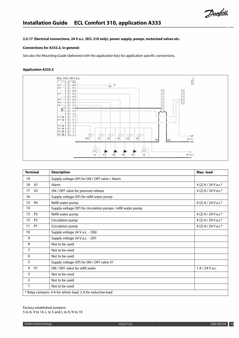
2.5.17 Electrical connections, 24 V a.c. (ECL 310 only), power supply, pumps, motorized valves etc.
Connections for A333.3, in general:
See also the Mounting Guide (delivered with the application key) for application specific connections.
Application A333.3
Terminal Description Max. load
19 Supply voltage (SP) for ON / OFF valve / Alarm
18 A1 Alarm 4 (2) A / 24 V a.c.*
17 V2 ON / OFF valve for pressure release 4 (2) A / 24 V a.c.*
16 Supply voltage (SP) for refill water pump
15 P4 Refill water pump 4 (2) A / 24 V a.c.*14 Supply voltage (SP) for circulation pumps / refill water pump
13 P3 Refill water pump 4 (2) A / 24 V a.c.*
12 P2 Circulation pump 4 (2) A / 24 V a.c.*
11 P1 Circulation pump 4 (2) A / 24 V a.c.*
10 Supply voltage 24 V a.c. - (SN)
9 Supply voltage 24 V a.c. - (SP)
8 Not to be used
7 Not to be used
6 Not to be used
5 Supply voltage (SP) for ON / OFF valve V1
4 V1 ON / OFF valve for refill water 1 A / 24 V a.c.
3 Not to be used
2 Not to be used
1 Not to be used
* Relay contacts: 4 A for ohmic load, 2 A for inductive load
Factory established jumpers:5 to 8, 9 to 14, L to 5 and L to 9, N to 10
Danfoss District Energy VI.GU.T1.02 DEN-SMT/DK 35

Installation Guide ECL Comfort 310, application A333
Wire cross section: 0.5 - 1.5 mm²Incorrect connection can damage the electronic outputs.Max. 2 x 1.5 mm² wires can be inserted into each screw terminal.
Do not connect 230 V a.c. powered components to a 24 V a.c. powersupplied controller directly. Use auxilliary relays (K) to separate 230V a.c. from 24 V a.c.
36 DEN-SMT/DK VI.GU.T1.02 Danfoss District Energy

Installation Guide ECL Comfort 310, application A333
2.5.18 Electrical connections, ECA 32
Connections for A333.2 and A333.3, in general:
See also the Mounting Guide (delivered with the application key) for application specific connections.
Terminal Description Max. load
39 R10 Relay 10, not used 4 (2) A / 24 V a.c.*
40 R10
41 R9 Relay 9, not used 4 (2) A / 24 V a.c.*
42 R9
43 R8 Relay 8, not used 4 (2) A / 24 V a.c.*44 R8
45 R8
46 R7 Relay 7 4 (2) A / 24 V a.c.*
47 R7 V3, ON / OFF valve for pressure release
48 R7 Phase for ON / OFF valve V3
49 Common terminal for input signals
50 S11 Input: Position signal from M1, 0 - 10 volt
51 S12 Input: Refill water level in storage tank, 0 - 10 volt
52 S13 Input: F2 flow signal, 0 - 10 volt
53 Input: not used
54 Input: not used
55 Input: not used
56 Reference terminal for Analogue out 2 (M2) and 3 (M3)
57 F1 Input: Flow-meter, pulse type
58 F2 Input: Flow-meter, pulse type
59 M1 Analogue out 1: 0 - 10 volt for control of motorized control valve M1 (A333.3) 2 mA **
60 M2 Analogue out 2: 0 - 10 volt for speed control of refill water pumps P3 and P4 (A333.2, A333.3) 2 mA **
61 M3 Analogue out 3: 0 - 10 volt for speed control of circulation pumps P1 and P2 (A333.2, A333.3) 2 mA **
62 Reference terminal for Analogue out 1 (M1)
* Relay contacts: 4 A for ohmic load, 2 A for inductive load
** Min. resistance: 5 KΩ
Danfoss District Energy VI.GU.T1.02 DEN-SMT/DK 37

Installation Guide ECL Comfort 310, application A333
2.5.19 Electrical connections, 24 V a.c., power supply, ON / OFF valve V3 controlled from relay output in ECA 32
Connections for A333.2 and A333.3, in general:See also the Mounting Guide (delivered with the application key) for application specific connections.
Application A333.2 / A333.3
2.5.20 Electrical connections, 24 V a.c., power supply, motorized control valve M1 controlled by 0 - 10 volt from ECA 32
Connections for A333.3, in general:See also the Mounting Guide (delivered with the application key) for application specific connections.
Application A333.3
The transformer for supplying the actuator must be a double-isolated version.The ECL Comfort 310 and the actuator for the control valve M1 must have separate transformers.
38 DEN-SMT/DK VI.GU.T1.02 Danfoss District Energy
Installation Guide ECL Comfort 310, application A333
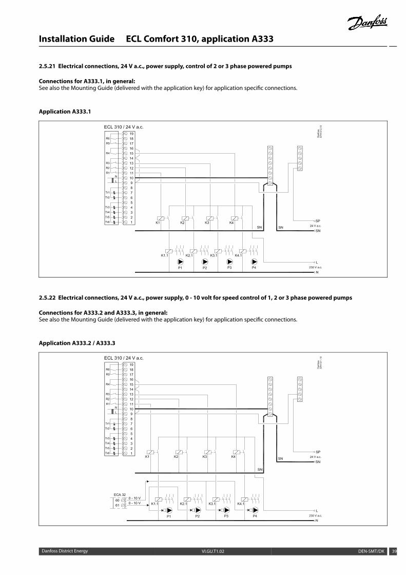
2.5.21 Electrical connections, 24 V a.c., power supply, control of 2 or 3 phase powered pumps
Connections for A333.1, in general:See also the Mounting Guide (delivered with the application key) for application specific connections.
Application A333.1
2.5.22 Electrical connections, 24 V a.c., power supply, 0 - 10 volt for speed control of 1, 2 or 3 phase powered pumps
Connections for A333.2 and A333.3, in general:See also the Mounting Guide (delivered with the application key) for application specific connections.
Application A333.2 / A333.3
Danfoss District Energy VI.GU.T1.02 DEN-SMT/DK 39

Installation Guide ECL Comfort 310, application A333
2.5.23 Electrical connections, 24 V a.c., power supply, ON / OFF control and speed control (via Frequency Converter) of 1, 2or 3 phase powered pumps
Connections for A333.2 and A333.3, in general:See also the Mounting Guide (delivered with the application key) for application specific connections.
Application A333.2 / A333.3
FC = Frequency Converter
Electrical connections for external Start / Stop control of a Frequency Converter:See examples in "Electrical connections, 230 V a.c.”
40 DEN-SMT/DK VI.GU.T1.02 Danfoss District Energy

Installation Guide ECL Comfort 310, application A333
2.5.24 Electrical connections, Pt 1000 temperature sensors and signals
Connections for A333, in general:See also the Mounting Guide (delivered with the application key)for application specific connections.
Terminal Sensor / description Type(recomm.)
29 and 30 S1 Outdoor temperaturesensor*
ESMT
28 and 30 S2 Primary supply temperaturesensor
ESM-11 / ESMB /ESMC / ESMU
27 and 30 S3 Secondary flow temperaturesensor **
ESM-11 / ESMB /ESMC / ESMU
26 and 30 S4 Secondary returntemperature sensor
ESM-11 / ESMB /ESMC / ESMU
25 and 30 S5 Primary return temperaturesensor
ESM-11 / ESMB /ESMC / ESMU
24 and 30 Not used
23 and 30 S7 Pressure signal (0 - 10 volt)
22 and 30 S8 Pressure signal (0 - 10 volt)
21 and 30 S9 Pressure signal (0 - 10 volt)
20 and 30 S10 Pressure signal (0 - 10 volt)
* If the outdoor temperature sensor is not connected or thecable is short-circuited, the controller assumes that theoutdoor temperature is 0 (zero) °C.
** The sensor must always be connected in order to have thedesired functionality. If the sensor is not connected or thecable is short-circuited, the motorized control valve closes(safety function).
Danfoss District Energy VI.GU.T1.02 DEN-SMT/DK 41

Installation Guide ECL Comfort 310, application A333
2.5.25 Electrical connections, pressure transmitters, 0 - 10 volt types
S7, S8, S9, S10
2.5.26 Electrical connections, pressure transmitters, 4 - 20 mA types
S7, S8, S9, S10
4 - 20 mA through a resistor of 500 ohm gives a voltage of 2 - 10 volt.
42 DEN-SMT/DK VI.GU.T1.02 Danfoss District Energy

Installation Guide ECL Comfort 310, application A333
2.5.27 Electrical connections, ECA 32
Connections for A333.2 and A333.3, in general:See also the Mounting Guide (delivered with the application key)for application specific connections.
Terminal Sensor / description
50 and 49 S11 Position signal from M1, 0 - 10 volt
51 and 49 S12 Refill water level in storage tank, 0 - 10 volt
52 and 49 S13 F2 flow signal, 0 - 10 volt
53 and 49 Not used
54 and 49 Not used
55 and 49 Not used
56 Used for output signal
57 and 49 F1 Water meter (flow meter), pulse type
58 and 49 F2 Flow meter, pulse type
Water and flowmeters, possibilities:
Water meter F1(flow meter)
- pulse type- M-Bus
Flow meter F2(flow meter)
- pulse type- 0 - 10 volt type- M-Bus
Danfoss District Energy VI.GU.T1.02 DEN-SMT/DK 43

Installation Guide ECL Comfort 310, application A333
2.5.28 Electrical connections, ECA 32, flow meters, pulse types
A333.2 / A333.3F1 and F2, pulse input
2.5.29 Electrical connections, ECA 32, flow meter, 0 - 10 volt type
A333.2 / A333.3F2 to input S13 (0 - 10 volt input)
44 DEN-SMT/DK VI.GU.T1.02 Danfoss District Energy
Installation Guide ECL Comfort 310, application A333
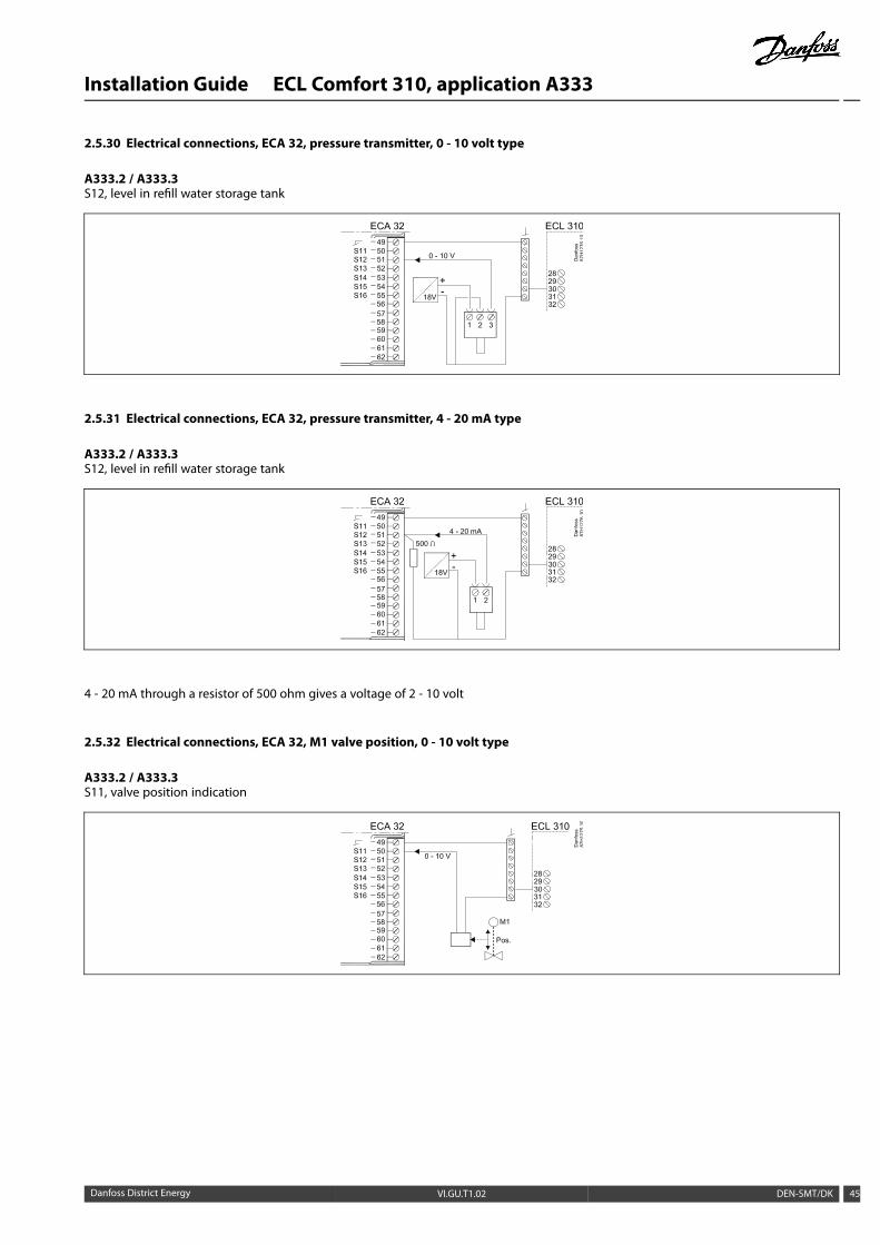
2.5.30 Electrical connections, ECA 32, pressure transmitter, 0 - 10 volt type
A333.2 / A333.3S12, level in refill water storage tank
2.5.31 Electrical connections, ECA 32, pressure transmitter, 4 - 20 mA type
A333.2 / A333.3S12, level in refill water storage tank
4 - 20 mA through a resistor of 500 ohm gives a voltage of 2 - 10 volt
2.5.32 Electrical connections, ECA 32, M1 valve position, 0 - 10 volt type
A333.2 / A333.3S11, valve position indication
Danfoss District Energy VI.GU.T1.02 DEN-SMT/DK 45

Installation Guide ECL Comfort 310, application A333
2.5.33 Electrical connections, ECA 30 / 31
TerminalECL
TerminalECA 30 / 31
Description Type(recomm.)
30 4
31 1Twisted pair
32 2
33 3Twisted pair
Cable 2 xtwisted pair
4
5Ext. room temperaturesensor* ESM-10
* After an external room temperature sensor has been connected,ECA 30 / 31 must be repowered.
The communication to the ECA 30 / 31 must be set up in the ECLComfort controller in 'ECA addr.'
The ECA 30 / 31 must be set up accordingly.
After application setup the ECA 30 / 31 is ready after 2–5 min. Aprogress bar in the ECA 30 / 31 is displayed.
ECL 210 / 310ECA 30 / 31
A
A
B
B
Dan
foss
87H
2051
.10
ESM-10
If the actual application contains two heating circuits, it is possibleto connect an ECA 30 / 31 to each circuit. The electrical connectionsare done in parallel.
Max. 2 ECA 30 / 31 can be connected to an ECL Comfort 310 controlleror to ECL Comfort 310 controllers in a master-slave system.
Setup procedures for ECA 30 / 31: See section ‘Miscellaneous’.
46 DEN-SMT/DK VI.GU.T1.02 Danfoss District Energy
Installation Guide ECL Comfort 310, application A333
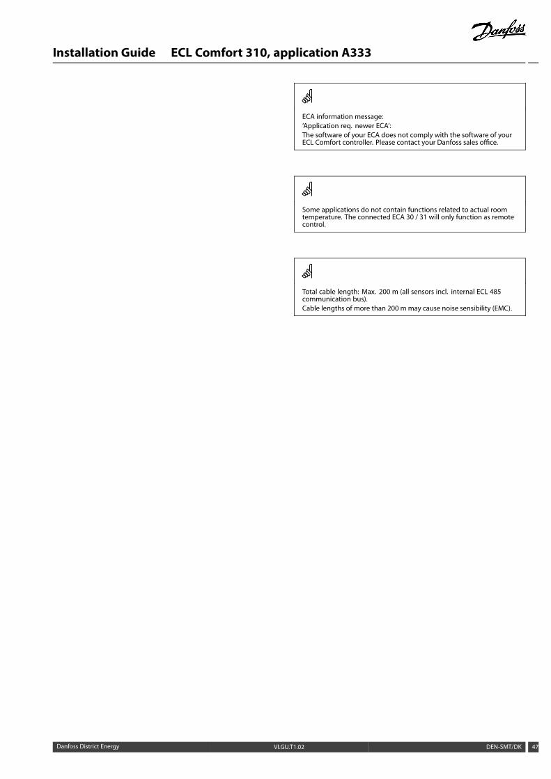
ECA information message:‘Application req. newer ECA’:The software of your ECA does not comply with the software of yourECL Comfort controller. Please contact your Danfoss sales office.
Some applications do not contain functions related to actual roomtemperature. The connected ECA 30 / 31 will only function as remotecontrol.
Total cable length: Max. 200 m (all sensors incl. internal ECL 485communication bus).Cable lengths of more than 200 m may cause noise sensibility (EMC).
Danfoss District Energy VI.GU.T1.02 DEN-SMT/DK 47

Installation Guide ECL Comfort 310, application A333
2.5.34 Electrical connections, master / slave systems
The controller can be used as master or slave in master / slavesystems via the internal ECL 485 communication bus (2 x twistedpair cable).
The ECL 485 communication bus is not compatible with the ECLbus in ECL Comfort 110, 200, 300 and 301!
Terminal Description Type(recomm.)
30 Common terminal
31* +12 V*, ECL 485 communication bus
32 B, ECL 485 communication bus
33 A, ECL 485 communication bus
Cable 2 xtwisted pair
* Only for ECA 30 / 31 and master / slave communication
Dan
foss
87H
2052
.10
A
A
B
B
A
A
B
B
Total cable length: Max. 200 m (all sensors incl. internal ECL 485communication bus).Cable lengths of more than 200 m may cause noise sensibility (EMC).
48 DEN-SMT/DK VI.GU.T1.02 Danfoss District Energy
Installation Guide ECL Comfort 310, application A333
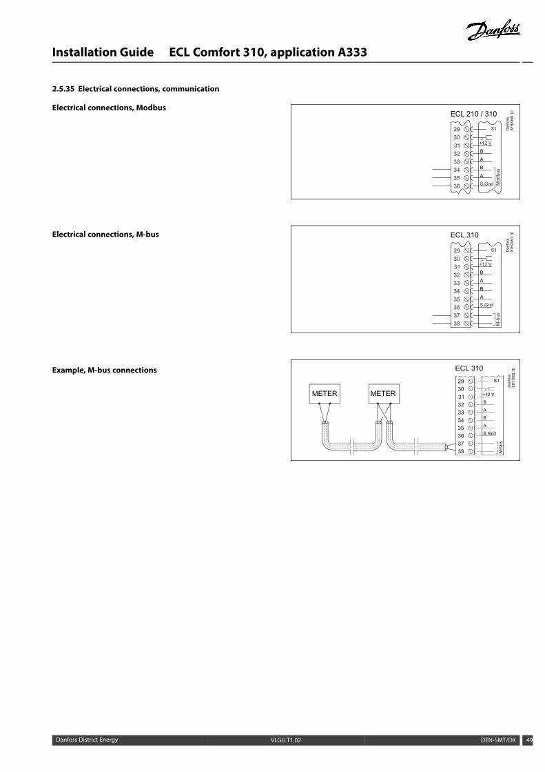
2.5.35 Electrical connections, communication
Electrical connections, Modbus
Electrical connections, M-bus
Example, M-bus connections
ECL 210 / 310
Dan
foss
87H
2060
.10
A
A
B
B
ECL 310
Dan
foss
87H
2061
.10
A
A
B
B
Danfoss District Energy VI.GU.T1.02 DEN-SMT/DK 49
Installation Guide ECL Comfort 310, application A333
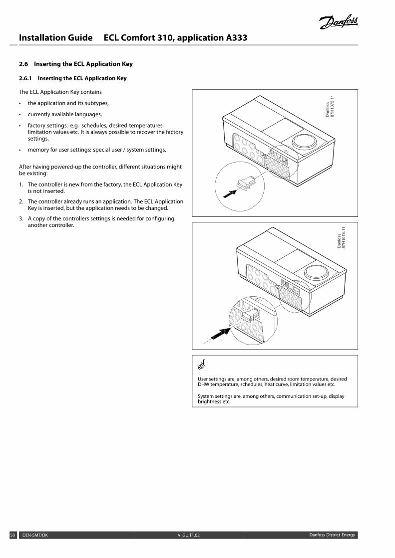
2.6 Inserting the ECL Application Key
2.6.1 Inserting the ECL Application Key
The ECL Application Key contains
• the application and its subtypes,
• currently available languages,
• factory settings: e.g. schedules, desired temperatures,limitation values etc. It is always possible to recover the factorysettings,
• memory for user settings: special user / system settings.
After having powered-up the controller, different situations mightbe existing:
1. The controller is new from the factory, the ECL Application Keyis not inserted.
2. The controller already runs an application. The ECL ApplicationKey is inserted, but the application needs to be changed.
3. A copy of the controllers settings is needed for configuringanother controller.
User settings are, among others, desired room temperature, desiredDHW temperature, schedules, heat curve, limitation values etc.
System settings are, among others, communication set-up, displaybrightness etc.
50 DEN-SMT/DK VI.GU.T1.02 Danfoss District Energy

Installation Guide ECL Comfort 310, application A333
Automatic update of controller software:The software of the controller is updated automatically when the keyis inserted (as of controller version 1.11). The following animation willbe shown when the software is being updated:
Progress bar
During update:
• Do not remove the KEYIf the key is removed before the hour-glass is shown, you haveto start afresh.
• Do not disconnect the powerIf the power is interrupted when the hour-glass is shown, thecontroller will not work.
Key inserted / not inserted, description:
ECL Comfort 210 / 310, controller versions lower than 1.36:
- Take out the application key; for 20 minutessettings can be changed.
- Power up the controller without theapplication key inserted; for 20 minutessettings can be changed.
ECL Comfort 210 / 310, controller versions 1.36 and up:
- Take out the application key; for 20 minutessettings can be changed.
- Power up the controller without theapplication key inserted; settings cannot bechanged.
Danfoss District Energy VI.GU.T1.02 DEN-SMT/DK 51

Installation Guide ECL Comfort 310, application A333
Application Key: Situation 1The controller is new from the factory, the ECL Application Keyis not inserted.
An animation for the ECL Application Key insertion is displayed.Insert the Application Key .
Application Key name and Version is indicated (example: A266Ver. 1.03).
If the ECL Application Key is not suitable for the controller, a "cross"is displayed over the ECL Application Key-symbol.
Action: Purpose: Examples:
Select language
Confirm
Select application
Confirm with ‘Yes’
Set 'Time & Date'Turn and push the dial to select andchange 'Hours', 'Minutes', 'Date','Month' and 'Year'.Choose ''Next'
Confirm with ‘Yes’
Go to ‘Aut. daylight’
Choose whether ‘Aut. daylight´ *should be active or not YES or NO
* ‘Aut. daylight’ is the automatic changeover between summerand winter time.
Depending on the contents of the ECL Application Key, procedureA or B is taking place:
AThe ECL Application key contains factory settings:The controller reads / transfers data from the ECL Application Keyto ECL controller.
The application is installed, and the controller resets and starts up.
BThe ECL Application key contains changed system settings:Push the dial repeatedly.
’NO’: Only factory settings from the ECL Application Key willbe copied to the controller.
’YES*: Special system settings (differing from the factorysettings) will be copied to the controller.
If the key contains user settings:Push the dial repeatedly.
‘NO: Only factory settings from the ECL Application Key willbe copied to the controller.
‘YES*: Special user settings (differing from the factory settings)will be copied to the controller.
* If ‘YES’ cannot be chosen, the ECL Application Key does notcontain any special settings.
Choose ‘Start copying’ and confirm with 'Yes'.
52 DEN-SMT/DK VI.GU.T1.02 Danfoss District Energy

Installation Guide ECL Comfort 310, application A333
Application Key: Situation 2The controller already runs an application. The ECL ApplicationKey is inserted, but the application needs to be changed.
To change to another application on the ECL Application Key, thecurrent application in the controller must be erased (deleted).
Be aware that the Application Key must be inserted.
Action: Purpose: Examples:
Choose ‘MENU’ in any circuit
Confirm
Choose the circuit selector at the topright corner in the display
Confirm
Choose ‘Common controller settings’
Confirm
Choose ‘Key functions’
Confirm
Choose ‘Erase application’
Confirm with ‘Yes’
The controller resets and is ready to be configured.
Follow the procedure described in situation 1.
Danfoss District Energy VI.GU.T1.02 DEN-SMT/DK 53
Installation Guide ECL Comfort 310, application A333
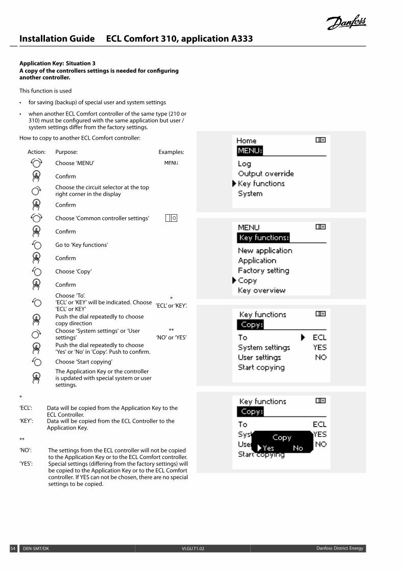
Application Key: Situation 3A copy of the controllers settings is needed for configuringanother controller.
This function is used
• for saving (backup) of special user and system settings
• when another ECL Comfort controller of the same type (210 or310) must be configured with the same application but user /system settings differ from the factory settings.
How to copy to another ECL Comfort controller:
Action: Purpose: Examples:
Choose ‘MENU’
Confirm
Choose the circuit selector at the topright corner in the display
Confirm
Choose 'Common controller settings'
Confirm
Go to ‘Key functions’
Confirm
Choose ‘Copy’
Confirm
Choose ‘To’.‘ECL’ or ‘KEY’ will be indicated. Choose’ECL’ or KEY’
*’ECL’ or ‘KEY’.
Push the dial repeatedly to choosecopy directionChoose ‘System settings’ or ‘Usersettings’
**‘NO’ or ‘YES’
Push the dial repeatedly to choose‘Yes’ or ‘No’ in ‘Copy’. Push to confirm.
Choose ‘Start copying’
The Application Key or the controlleris updated with special system or usersettings.
*
‘ECL’: Data will be copied from the Application Key to theECL Controller.
‘KEY’: Data will be copied from the ECL Controller to theApplication Key.
**
‘NO’: The settings from the ECL controller will not be copiedto the Application Key or to the ECL Comfort controller.
‘YES’: Special settings (differing from the factory settings) willbe copied to the Application Key or to the ECL Comfortcontroller. If YES can not be chosen, there are no specialsettings to be copied.
54 DEN-SMT/DK VI.GU.T1.02 Danfoss District Energy

Installation Guide ECL Comfort 310, application A333
2.6.2 ECL Application Key, copying data
General principlesWhen the controller is connected and operating, you can checkand adjust all or some of the basic settings. The new settings canbe stored on the Key.
How to update the ECL Application Key after settings havebeen changed?All new settings can be stored on the ECL Application Key.
How to store factory setting in the controller from theApplication Key?Please read the paragraph concerning Application Key, Situation1: The controller is new from the factory, the ECL Application Keyis not inserted.
How to store personal settings from the controller to the Key?Please read the paragraph concerning Application Key, Situation 3:A copy of the controllers settings is needed for configuring anothercontroller
As a main rule, the ECL Application Key should always remain inthe controller. If the Key is removed, it is not possible to changesettings.
Factory settings can always be restored.
Make a note of new settings in the 'Settings overview' table.
Do not remove the ECL Application Key while copying. The data onthe ECL Application Key can be damaged!
It is possible to copy settings from one ECL Comfort controller toanother controller provided that the two controllers are from the sameseries (210 or 310).
Key inserted / not inserted, description:
ECL Comfort 210 / 310, controller versions lower than 1.36:
- Take out the application key; for 20 minutessettings can be changed.
- Power up the controller without theapplication key inserted; for 20 minutessettings can be changed.
ECL Comfort 210 / 310, controller versions 1.36 and up:
- Take out the application key; for 20 minutessettings can be changed.
- Power up the controller without theapplication key inserted; settings cannot bechanged.
Danfoss District Energy VI.GU.T1.02 DEN-SMT/DK 55

Installation Guide ECL Comfort 310, application A333
2.7 Check list
Is the ECL Comfort controller ready for use?
Make sure that the correct power supply is connected to terminals 9 (Live) and 10 (Neutral).
Check that the required controlled components (actuator, pump etc.) are connected to the correct terminals.
Check that all sensors / signals are connected to the correct terminals (see 'Electrical connections').
Mount the controller and switch on the power.
Is the ECL Application Key inserted (see 'Inserting the Application Key').
Does the ECL Comfort controller contain an existing application (see 'Inserting the Application Key').
Is the correct language chosen (see 'Language' in 'Common controller settings').
Is the time & date set correctly (see 'Time & Date' in 'Common controller settings').
Is the right application chosen (see 'Identifying the system type').
Check that all settings in the controller (see 'Settings overview') are set or that the factory settings comply with yourrequirements.
Choose manual operation (see 'Manual control'). Check that valves open and close, and that required controlledcomponents (pump etc.) start and stop when operated manually.
Check that the temperatures / signals shown in the display match the actual connected components.
Having completed themanual operation check, choose controller mode (scheduled, comfort, saving or frost protection).
56 DEN-SMT/DK VI.GU.T1.02 Danfoss District Energy
Installation Guide ECL Comfort 310, application A333
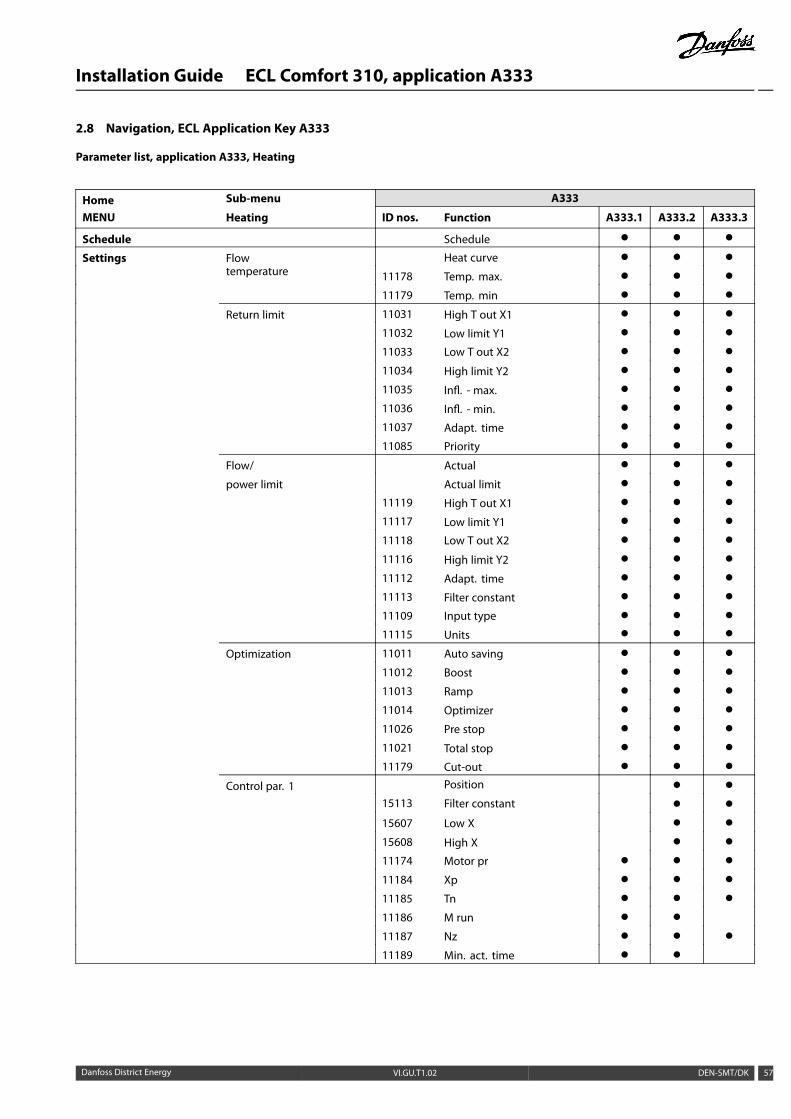
2.8 Navigation, ECL Application Key A333
Parameter list, application A333, Heating
Home Sub-menu A333
MENU Heating ID nos. Function A333.1 A333.2 A333.3
Schedule Schedule ( ( (
Settings Flowtemperature
Heat curve ( ( (
11178 Temp. max. ( ( (
11179 Temp. min ( ( (
Return limit 11031 High T out X1 ( ( (
11032 Low limit Y1 ( ( (
11033 Low T out X2 ( ( (
11034 High limit Y2 ( ( (
11035 Infl. - max. ( ( (
11036 Infl. - min. ( ( (
11037 Adapt. time ( ( (
11085 Priority ( ( (
Flow/ Actual ( ( (
power limit Actual limit ( ( (
11119 High T out X1 ( ( (
11117 Low limit Y1 ( ( (
11118 Low T out X2 ( ( (
11116 High limit Y2 ( ( (
11112 Adapt. time ( ( (
11113 Filter constant ( ( (
11109 Input type ( ( (
11115 Units ( ( (
Optimization 11011 Auto saving ( ( (
11012 Boost ( ( (
11013 Ramp ( ( (
11014 Optimizer ( ( (
11026 Pre stop ( ( (
11021 Total stop ( ( (
11179 Cut-out ( ( (
Control par. 1 Position ( (
15113 Filter constant ( (
15607 Low X ( (
15608 High X ( (
11174 Motor pr ( ( (
11184 Xp ( ( (
11185 Tn ( ( (
11186 M run ( (
11187 Nz ( ( (
11189 Min. act. time ( (
Danfoss District Energy VI.GU.T1.02 DEN-SMT/DK 57

Installation Guide ECL Comfort 310, application A333
Parameter list, application A333, Heating, continued
Home Sub-menu A333
MENU Heating ID nos. Function A333.1 A333.2 A333.3
Settings Control par., P refill 11321 Pressure, des. ( (
13184 Xp ( (
13185 Tn ( (
13187 Nz ( (
13197 Td ( (
13165 V.out, max. ( (
13167 V.out, min. ( (
11331 Sleep level ( (
111332 Sleep mode time ( (
11330 Wake-up level ( (
11333 Boost ( (
Control par., P circ. 12322 Pressure, diff. ( (
12184 Xp ( (
12185 Tn ( (
12187 Nz ( (
12197 Td ( (
12165 V.out, max. ( (
12167 V.out, min. ( (
Pump control 11322 Pressure diff. ( ( (
11314 Chan.-over time ( ( (
11310 Retry time ( ( (
11313 Stab. time ( ( (
11311 Change, duration ( ( (
11312 Change time ( ( (
11022 P exercise ( ( (
11316 Alarm handling ( ( (
Refill water Time left ( ( (
12311 Change duration ( ( (
11321 Pressure des. ( ( (
13322 Pressure diff. ( ( (
11318 Max. pressure ( ( (
11319 Max. press. diff. ( ( (
11323 Time-out ( ( (
11320 P exercise ( ( (
11325 Valve delay ( ( (
11326 No. of pumps ( ( (
12316 Alarm handling ( ( (
58 DEN-SMT/DK VI.GU.T1.02 Danfoss District Energy

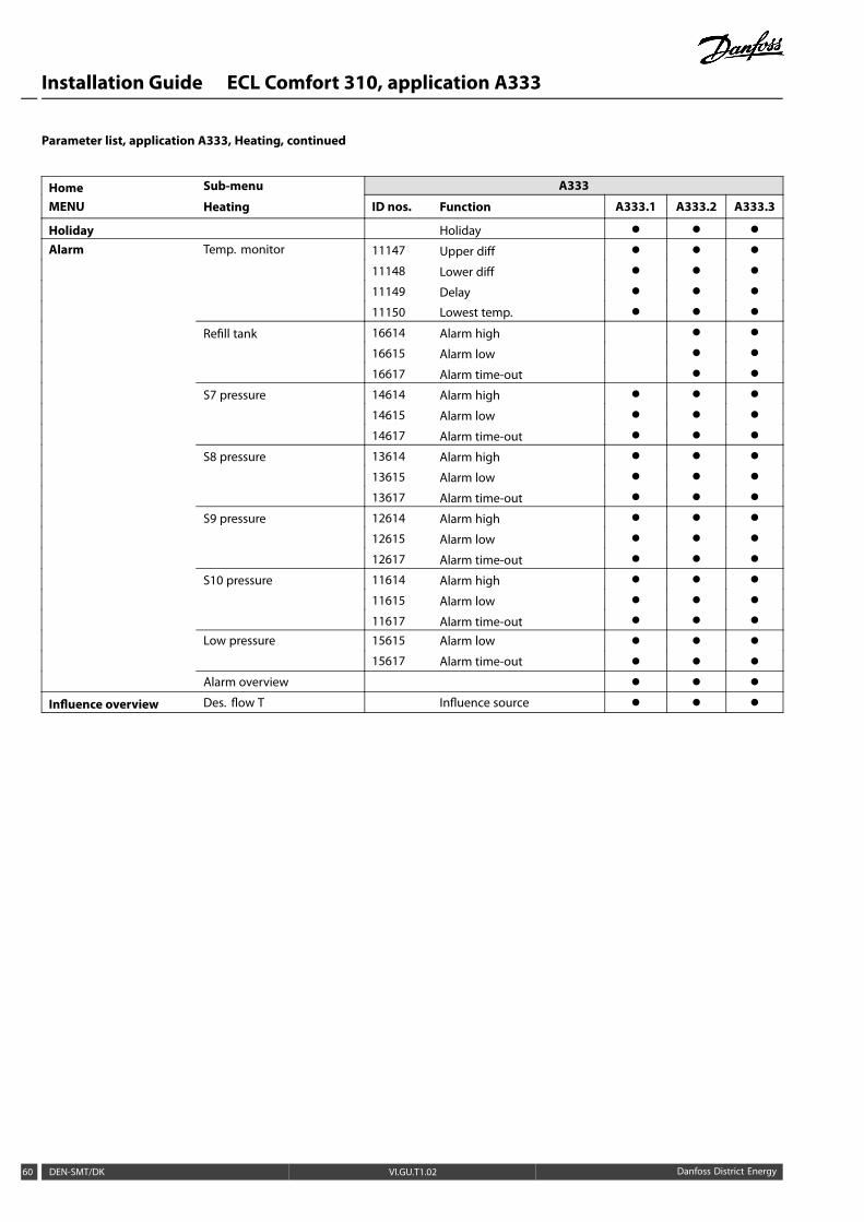
Installation Guide ECL Comfort 310, application A333
Parameter list, application A333, Heating, continued
Home Sub-menu A333
MENU Heating ID nos. Function A333.1 A333.2 A333.3
Settings Refill tank Level ( (
16113 Filter constant ( (
16607 Low X ( (
16608 High X ( (
16602 Level, desired ( (
16194 Stop difference ( (
16195 Start difference ( (
Application 11017 Demand offset ( ( (
11500 Send desired T ( ( (
11023 M exercise ( ( (
11052 DHW priority ( ( (
11077 P frost T ( ( (
11078 P heat T ( ( (
11093 Frost pr. T ( ( (
11141 Ext. input ( ( (
11142 Ext. mode ( ( (
Water meter CW consump. ( (
13513 Pulse value ( (
13514 Preset ( (
Flow meter Actual ( (
17607 Low X ( (
17608 High X ( (
17109 Input type ( (
17114 Pulse ( (
17115 Units ( (
S7 pressure Pressure ( ( (
14113 Filter constant ( ( (
14607 Low X ( ( (
14608 High X ( ( (
S8 pressure Pressure ( ( (
13113 Filter constant ( ( (
13607 Low X ( ( (
13608 High X ( ( (
S9 pressure Pressure ( ( (
12113 Filter constant ( ( (
12607 Low X ( ( (
12608 High X ( ( (
S10 pressure Pressure ( ( (
11113 Filter constant ( ( (
11607 Low X ( ( (
11608 High X ( ( (
Danfoss District Energy VI.GU.T1.02 DEN-SMT/DK 59
Installation Guide ECL Comfort 310, application A333
Parameter list, application A333, Heating, continued
Home Sub-menu A333
MENU Heating ID nos. Function A333.1 A333.2 A333.3
Holiday Holiday ( ( (
Alarm Temp. monitor 11147 Upper diff ( ( (
11148 Lower diff ( ( (
11149 Delay ( ( (
11150 Lowest temp. ( ( (
Refill tank 16614 Alarm high ( (
16615 Alarm low ( (
16617 Alarm time-out ( (
S7 pressure 14614 Alarm high ( ( (
14615 Alarm low ( ( (
14617 Alarm time-out ( ( (
S8 pressure 13614 Alarm high ( ( (
13615 Alarm low ( ( (
13617 Alarm time-out ( ( (
S9 pressure 12614 Alarm high ( ( (
12615 Alarm low ( ( (
12617 Alarm time-out ( ( (
S10 pressure 11614 Alarm high ( ( (
11615 Alarm low ( ( (
11617 Alarm time-out ( ( (
Low pressure 15615 Alarm low ( ( (
15617 Alarm time-out ( ( (
Alarm overview ( ( (
Influence overview Des. flow T Influence source ( ( (
60 DEN-SMT/DK VI.GU.T1.02 Danfoss District Energy

Installation Guide ECL Comfort 310, application A333
Parameter list, application A333, Common controller
Home Sub-menu A333
MENU Common controller ID nos. Function A333.1 A333.2 A333.3
Time & date ( ( (
Input overview ( ( (
Log ( ( (
Output override ( ( (
Key functions New application ( ( (
Application ( ( (
Factory setting ( ( (
Copy ( ( (
Key overview ( ( (
System ECL version ( ( (
Extension ( ( (
Ethernet ( ( (
Portal config. ( ( (
M-bus config. ( ( (
Energy meters ( ( (
Raw input overview ( ( (
Alarm ( ( (
Display ( ( (
Communication ( ( (
Language ( ( (
Danfoss District Energy VI.GU.T1.02 DEN-SMT/DK 61

Installation Guide ECL Comfort 310, application A333
3.0 Daily use
3.1 How to navigate
You navigate in the controller by turning the dial left or right tothe desired position ( ).
The dial has a built-in accellerator. The faster you turn the dial, thefaster it reaches the limits of any wide setting range.
The position indicator in the display ( ) will always show you whereyou are.
Push the dial to confirm your choices ( ).
The display examples are from a two-circuit application: Oneheating circuit ( ) and one domestic hot-water (DHW) circuit ( ).The examples might differ from your application.
Heating circuit ( ):
Some general settings which apply to the entire controller arelocated in a specific part of the controller.
To enter ‘Common controller settings’:
Action: Purpose: Examples:
Choose ‘MENU’ in any circuit
Confirm
Choose the circuit selector at the topright corner in the display
Confirm
Choose ‘Common controller settings’
Confirm
Circuit selector
62 DEN-SMT/DK VI.GU.T1.02 Danfoss District Energy
Installation Guide ECL Comfort 310, application A333
3.2 Understanding the controller display
This section describes the function in general for the ECL Comfort210 / 310 series. The shown displays are typical and not applicationrelated. They might differ from the displays in your application.
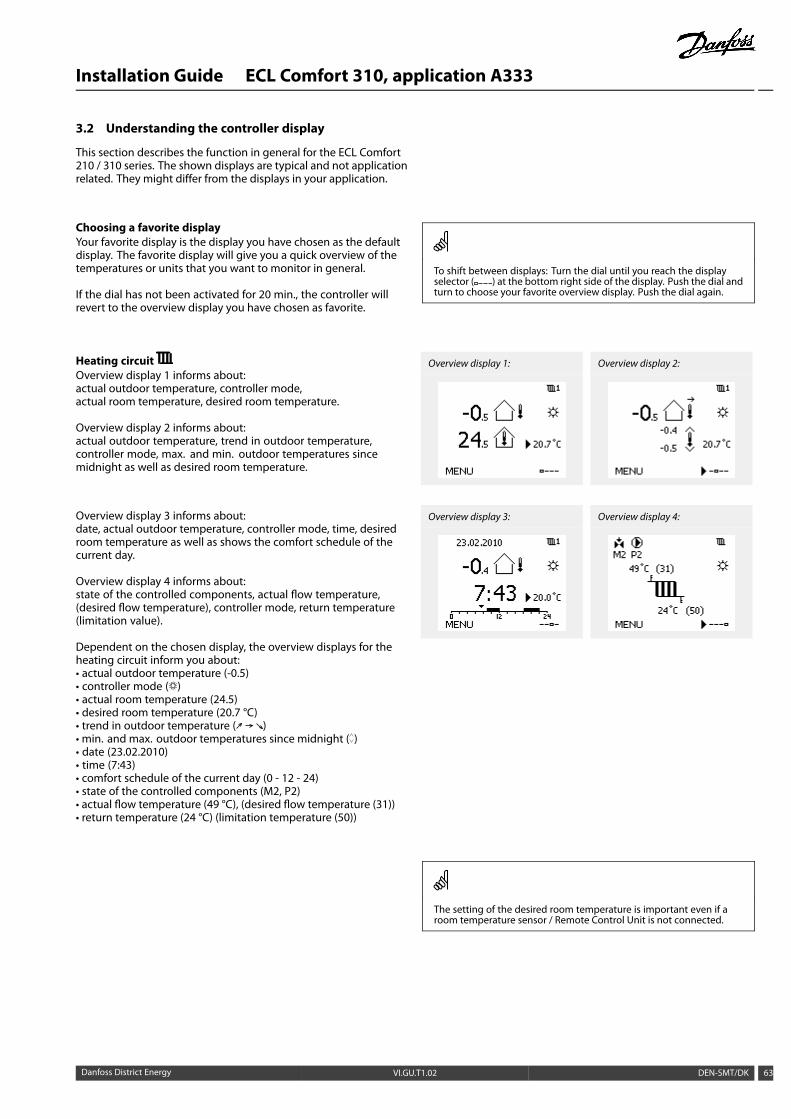
Choosing a favorite displayYour favorite display is the display you have chosen as the defaultdisplay. The favorite display will give you a quick overview of thetemperatures or units that you want to monitor in general.
If the dial has not been activated for 20 min., the controller willrevert to the overview display you have chosen as favorite.
To shift between displays: Turn the dial until you reach the displayselector ( ) at the bottom right side of the display. Push the dial andturn to choose your favorite overview display. Push the dial again.
Heating circuitOverview display 1 informs about:actual outdoor temperature, controller mode,actual room temperature, desired room temperature.
Overview display 2 informs about:actual outdoor temperature, trend in outdoor temperature,controller mode, max. and min. outdoor temperatures sincemidnight as well as desired room temperature.
Overview display 3 informs about:date, actual outdoor temperature, controller mode, time, desiredroom temperature as well as shows the comfort schedule of thecurrent day.
Overview display 4 informs about:state of the controlled components, actual flow temperature,(desired flow temperature), controller mode, return temperature(limitation value).
Dependent on the chosen display, the overview displays for theheating circuit inform you about:• actual outdoor temperature (-0.5)• controller mode ( )• actual room temperature (24.5)• desired room temperature (20.7 °C)• trend in outdoor temperature ( )• min. and max. outdoor temperatures since midnight ( )• date (23.02.2010)• time (7:43)• comfort schedule of the current day (0 - 12 - 24)• state of the controlled components (M2, P2)• actual flow temperature (49 °C), (desired flow temperature (31))• return temperature (24 °C) (limitation temperature (50))
Overview display 1: Overview display 2:
Overview display 3: Overview display 4:
The setting of the desired room temperature is important even if aroom temperature sensor / Remote Control Unit is not connected.
Danfoss District Energy VI.GU.T1.02 DEN-SMT/DK 63

Installation Guide ECL Comfort 310, application A333
If the temperature value is displayed as
"- -" the sensor in question is not connected.
"- - -" the sensor connection is short-circuited.
Setting the desired temperature
Depending on the chosen circuit and mode, it is possible to enterall daily settings directly from the overview displays (see also thenext page concerning symbols).
Setting the desired room temperature
The desired room temperature can easily be adjusted in theoverview displays for the heating circuit.
Action: Purpose: Examples:
Desired room temperature 20.5
Confirm
Adjust the desired room temperature 21.0
Confirm
This overview display informs about outdoor temperature, actualroom temperature as well as desired room temperature.
The display example is for comfort mode. If you want to changethe desired room temperature for saving mode, choose the modeselector and select saving.
The setting of the desired room temperature is important even if aroom temperature sensor / Remote Control Unit is not connected.
Setting the desired room temperature, ECA 30 / ECA 31
The desired room temperature can be set exactly as in thecontroller. However, other symbols can be present in the display(please see 'What do the symbols mean?').
With the ECA 30 / ECA 31 you can override the desired roomtemperature set in the controller temporarily by means of the overridefunctions:
64 DEN-SMT/DK VI.GU.T1.02 Danfoss District Energy

Installation Guide ECL Comfort 310, application A333
3.3 A general overview: What do the symbols mean?
Symbol Description
Outdoor temp.
Relative humidity indoor
Room temp.
DHW temp.
Temperature
Position indicator
Scheduled mode
Comfort mode
Saving mode
Frost protection mode
Manual mode
Standby
Cooling mode
! Active output override
Optimized start or stop time
Mode
Heating
Cooling
DHW
Common controller settings
Circuit
Pump ON
Pump OFF
Actuator opens
Actuator closes
42 Actuator, analogue controlsignal
Controlledcomponent
Symbol Description
Alarm
Monitoring temperature sensorconnection
Display selector
Max. and min. value
Trend in outdoor temperature
Wind speed sensor
Sensor not connected or not used
Sensor connection short-circuited
7-23 Fixed comfort day (holiday)
Active influence
Heating active
Cooling active
Additional symbols, ECA 30 / 31:
Symbol Description
ECA Remote Control Unit
15 Connection address (master: 15, slaves: 1 - 9)
Day off
Holiday
Relaxing (extended comfort period)
Going out (extended saving period)
In ECA 30 / 31 only the symbols that are relevant to the application inthe controller are displayed.
Danfoss District Energy VI.GU.T1.02 DEN-SMT/DK 65
Installation Guide ECL Comfort 310, application A333
3.4 Monitoring temperatures and system components
This section describes the function in general for the ECL Comfort210 / 310 series. The shown displays are typical and not applicationrelated. They might differ from the displays in your application.
Heating circuit
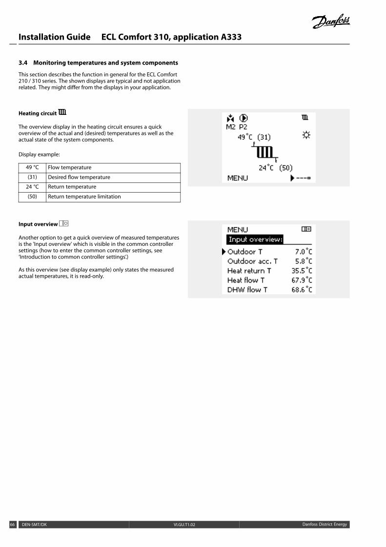
The overview display in the heating circuit ensures a quickoverview of the actual and (desired) temperatures as well as theactual state of the system components.
Display example:
49 °C Flow temperature
(31) Desired flow temperature
24 °C Return temperature
(50) Return temperature limitation
Input overview
Another option to get a quick overview of measured temperaturesis the 'Input overview' which is visible in the common controllersettings (how to enter the common controller settings, see‘Introduction to common controller settings’.)
As this overview (see display example) only states the measuredactual temperatures, it is read-only.
66 DEN-SMT/DK VI.GU.T1.02 Danfoss District Energy

Installation Guide ECL Comfort 310, application A333
3.5 Influence overview
This section describes the function in general for the ECL Comfort210 / 310 series. The shown displays are typical and not applicationrelated. They might differ from the displays in your application.
The menu gives an overview of the influences on the desiredflow temperature. It differs from application to application whichparameters are listed. It can be helpful in a service situation toexplain unexpected conditions or temperatures among others.
If the desired flow temperature is influenced (corrected) by one ormore parameters, it is indicated by a small line with arrow-down,arrow-up or double-arrow:
Arrow-down:The parameter in question reduces the desired flow temperature.
Arrow-up:The parameter in question increases the desired flow temperature.
Double-arrow:The parameter in question creates an override (e.g. Holiday).
Straight line:No active influence.
In the example, the arrow in the symbol points downwards for'Room lim.'. This means that the actual room temperature ishigher than the desired room temperature which again results in adecrease of the desired flow temperature.
Danfoss District Energy VI.GU.T1.02 DEN-SMT/DK 67

Installation Guide ECL Comfort 310, application A333
3.6 Manual control
This section describes the function in general for the ECL Comfort210 / 310 series. The shown displays are typical and not applicationrelated. They might differ from the displays in your application.
It is possible to manually control the installed components.
Manual control can only be selected in favorite displays in whichthe symbols for the controlled components (valve, pump etc.) arevisible.
Action: Purpose: Examples:
Choose mode selector
Confirm
Choose manual mode
Confirm
Choose pump
Confirm
Switch ON the pump
Switch OFF the pump.
Confirm pump mode
Choose motorized control valve
Confirm
Open the valve
Stop opening the valve
Close the valve
Stop closing the valve
Confirm valve mode
To leave manual control, use the mode selector to select thedesired mode. Push the dial.
Manual control is typically used when commisioning theinstallation. The controlled components, valve, pump etc., can becontrolled for correct function.
Controlled components Circuit selector
During manual operation:
• All control functions are deactivated
• Output override is not possible
• Frost protection is not active
When manual control is selected for one circuit, it is automaticallyselected for all circuits!
68 DEN-SMT/DK VI.GU.T1.02 Danfoss District Energy

Installation Guide ECL Comfort 310, application A333
3.7 Schedule
3.7.1 Set your schedule
This section describes the schedule in general for the ECL Comfort210 / 310 series. The shown displays are typical and not applicationrelated. They might differ from the displays in your application.In some applications, however, there might be more than oneschedule. Additional schedules can be found in ‘Commoncontroller settings’.
The schedule consists of a 7-day week:
M = Monday
T = Tuesday
W = Wednesday
T = Thursday
F = Friday
S = Saturday
S = Sunday
The schedule will day-by-day show you the start and stop times ofyour comfort periods (heating / DHW circuits).
Changing your schedule:
Action: Purpose: Examples:Choose 'MENU' in any of the overviewdisplays
Confirm
Confirm the choice 'Schedule'
Choose the day to change
Confirm* T
Go to Start1
Confirm
Adjust the time
Confirm
Go to Stop1, Start2 etc. etc.
Return to 'MENU'
Confirm
Choose 'Yes' or 'No' in 'Save'
Confirm
* Several days can be marked
The chosen start and stop times will be valid for all the chosen days(in this example Thursday and Saturday).
You can set max. 3 comfort periods a day. You can delete a comfortperiod by setting start and stop times to the same value.
Each circuit has its own schedule. To change to another circuit, go to'Home', turn the dial and choose the desired circuit.
The start and stop times can be set in half-hourly (30 min. ) intervals.
Danfoss District Energy VI.GU.T1.02 DEN-SMT/DK 69

Installation Guide ECL Comfort 310, application A333
4.0 Settings overview
All parameters related to heating are listed as circuit 1.It is recommendable to make a note of any changed settings in the empty columns.
Setting ID Page Factory settings in circuit(s)
1 2 3
Heat curve 74 1.0
Temp. max. (flow temp. limit, max.) 11178 75 90 °C
Temp. min. (flow temp. limit, min.) 11177 75 10 °C
High T out X1 (return temp. limitation, high limit, X-axis) 11031 76 15 °C
Low limit Y1 (return temp. limitation, low limit, Y-axis) 11032 76 40 °C
Low T out X2 (return temp. limitation, low limit, X-axis) 11033 76 -15 °C
High limit Y2 (return temp. limitation, high limit, Y-axis) 11034 77 60 °C
Infl. - max. (return temp. limitation - max. influence) 11035 77 -2.0
Infl. - min. (return temp. limitation - min. influence) 11036 77 0.0
Adapt. time (adaptation time) 11037 78 25 s
Priority (priority for return temp. limitation) 11085 78 OFF
Actual (actual flow or power) 11110 79
Actual limit (limitation value) 11111 79
High T out X1 (flow / power limitation, high limit, X-axis) 11119 79 15 °C
Low limit Y1 (flow / power limitation, low limit, Y-axis) 11117 80 999.9l/h
Low T out X2 (flow / power limitation, low limit, X-axis) 11118 80 -15 °C
High limit Y2 (flow / power limitation, high limit, Y-axis) 11116 80 999.9l/h
Adapt. time (adaptation time) 11112 80 OFF
Filter constant 11113 80 10
Input type 11109 81 OFF
Units 11115 81 l / h
Auto saving (saving temp. dependent on outdoor temp.) 11011 82 -15 °C
Boost 11012 82 OFF
Ramp (reference ramping) 11013 83 OFF
Optimizer (optimizing time constant) 11014 83 OFF
Pre-stop (optimized stop time) 11026 84 ON
Total stop 11021 84 OFF
Cut-out (limit for heating cut-out) 11179 85 18 °C
Position (A333.2 / A333.3) Read-out 87 *)
Filter constant (A333.2 / A333.3) 15113 87 2
Low X (A333.2 / A333.3) 15607 88 2.0 V
High X (A333.2 / A333.3) 15608 88 10.0 V
Motor pr. (motor protection) — only A333.1, A333.2 11174 88 OFF
Xp (proportional band) 11184 89 80 K
Tn (integration time constant) 11185 89 30 sM run (running time of the motorized control valve)— onlyA333.1, A333.2 11186 89 50 s
Nz (neutral zone) 11187 89 3 K
Min. act. time (min. activation time gear motor)— 11189 90 3
Pressure des. (A333.2 / A333.3) 11321 92 3.0 bar
Xp (proportional band) (A333.2 / A333.3) 13184 92 25 bar
70 DEN-SMT/DK VI.GU.T1.02 Danfoss District Energy

Installation Guide ECL Comfort 310, application A333
Setting ID Page Factory settings in circuit(s)
1 2 3
Tn (integration time ) (A333.2 / A333.3) 13185 93 25 sec
Nz (neutral zone) (A333.2 / A333.3) 13187 93 0.4 bar
Td (Time derivative) (A333.2 / A333.3) 13197 93 0 sec
V out max. (A333.2 / A333.3) 13165 93 100 %
V out min. (A333.2 / A333.3) 13167 94 0 %
Sleep level (A333.2 / A333.3) 11331 94 20 %
Sleep mode time (A333.2 / A333.3) 11332 94 10 sec
Wake up level (A333.2 / A333.3) 11330 95 40 %
Boost (A333.2 / A333.3) 11333 95 5 %
Pressure diff. (A333.2 / A333.3) 12322 96 1.5 bar
Xp (proportional band) (A333.2 / A333.3) 12184 97 10 bar
Tn (integration time ) (A333.2 / A333.3) 12185 97 5 sec
Nz (neutral zone) (A333.2 / A333.3) 12187 97 1.0 bar
Td (Time derivative) (A333.2 / A333.3) 12197 97 0 sec
V out max. (A333.2 / A333.3) 12165 98 100 %
V out min. (A333.2 / A333.3) 12167 98 0 %
Pressure diff. 11322 99 1.5 bar
Chan.-over time (change-over time) 11314 99 15 sec
Retry time 11310 100 OFF
Stab. time (stabilization time) 11313 100 50 sec
Change, duration 11311 100 7 days
Change time 11312 101 12
P exercise (pump exercise) 11022 101 OFF
Alarm handling 11316 101 OFF
Tiime Left Read-out 102 -
Change duration 12311 103 7 days
Pressure des. 11321 103 3.0 bar
Pressure diff. 13322 104 1.5 bar
Max. pressure 11318 104 40.0 bar
Max. pressure diff. 11319 105 -0.5 bar
Time-out 11323 106 100 sec
P exercise (pump exercise) 11022 107 OFF
Valve delay 11325 107 1 sec
No. of pumps 11326 107 1
Alarm handling 12316 108 OFF
Level (A333.2 / A333.3) Read-out 109 *)
Filter constant 16113 110 4
Low X (A333.2 / A333.3) 16607 110 2.0 V
High X (A333.2 / A333.3) 16608 110 10.0 V
Level, desired (A333.2 / A333.3) 16602 111 3.0 m
Stop difference (A333.2 / A333.3) 16194 111 0.5 m
Start difference (A333.2 / A333.3) 16195 111 –0.5 m
Demand offset 11017 112 OFF
Send desired T 11500 112 ON
Danfoss District Energy VI.GU.T1.02 DEN-SMT/DK 71

Installation Guide ECL Comfort 310, application A333
Setting ID Page Factory settings in circuit(s)
1 2 3
M exercise (valve exercise) 11023 112 OFF
DHW priority (closed valve / normal operation) 11052 113 OFF
P frost T 11077 113 2 °C
P heat T (heat demand) 11078 113 20 °C
Frost pr. T (frost protection temperature) 11093 113 10 °C
Ext. input (external override) 11141 114 OFF
Ext. mode (external override mode) 11142 115 COM-FORT
CW consump. (A333.2 / A333.3) Read-out 116 -
Pulse value (A333.2 / A333.3) 13513 116 10.0 l
Preset (A333.2 / A333.3) 13514 116 OFF
Actual (A333.2 / A333.3) Read-out 117 *)
Low X (A333.2 / A333.3) 17607 118 2.0 V
High X (A333.2 / A333.3) 17608 118 10.0 V
Input type (A333.2 / A333.3) 17109 118 OFF
Pulse (A333.2 / A333.3) 17114 119 OFF
Units (A333.2 / A333.3) 17115 119 l/h
Pressure (S7, S8, S9, S10) Read-out 121 *)
Filter constant (S7, S8, S9, S10) 1x113 121 4
Low X (S7, S8, S9, S10) 1x607 122 2.0 V
High X (S7, S8, S9, S10) 1x608 122 10.0 V
Upper difference 11147 123 OFF
Lower difference 11148 123 OFF
Delay 11149 124 10 m
Lowest temp. 11150 124 30 °C
Alarm high (A333.2 / A333.3) 16614 124 25.0 m
Alarm low (A333.2 / A333.3) 16615 125 0.0 m
Alarm time-out (A333.2 / A333.3) 16617 125 15 s
Alarm high 1x614 126 25.0 bar
Alarm low 1x615 126 25.0 bar
Alarm time-out 1x617 126 10 m
Alarm low 15615 126 25.0 bar
Alarm time-out 15617 127 10 s
Backlight (display brightness) 60058 137 5
Contrast (display contrast) 60059 137 3
Modbus addr. 38 138 1
ECL 485 addr. (master / slave address) 2048 138 15
Service Pin 2150 138 0
Ext. reset 2151 139 0
Language 2050 139 English
Room T Offset 141 0.0 K
RH offset (ECA 31 only) 142 0.0 %
Backlight (display brightness) 142 5
Contrast (display contrast) 142 3
Use as remote 142 *)
72 DEN-SMT/DK VI.GU.T1.02 Danfoss District Energy

Installation Guide ECL Comfort 310, application A333
Setting ID Page Factory settings in circuit(s)
1 2 3
Slave addr. (Slave address) 143 A
Connection addr. (Connection address) 143 15
Override addr. (Override address) 144 OFF
Override circuit 145 OFF
Danfoss District Energy VI.GU.T1.02 DEN-SMT/DK 73

Installation Guide ECL Comfort 310, application A333
5.0 Settings, circuit 1
5.1 Flow temperature
The ECL Comfort controller determines and controls the flowtemperature related to the outdoor temperature. This relationshipis called the heat curve.
The heat curve is set by means of 6 coordinate points. The desiredflow temperature is set at 6 pre-defined outdoor temperaturevalues.
The shown value for the heat curve is an average value (slope),based on the actual settings.
Outdoortemp. Desired flow temp. Your
settingsA B C
-30 °C 45 °C 75 °C 95 °C-15 °C 40 °C 60 °C 90 °C-5 °C 35 °C 50 °C 80 °C0 °C 32 °C 45 °C 70 °C5 °C 30 °C 40 °C 60 °C15 °C 25 °C 28 °C 35 °C
A: Example for floor heatingB: Factory settingsC: Example for radiator heating (high demand)
Heat curve
Circuit Setting range Factory setting
1 0.1 ... 4.0 1.0
The heat curve can be changed in two ways:
1. The value of the slope is changed (see heat curve exampleson next page)
2. The coordinates of the heat curve are changed
Change the value of the slope:Push the dial to enter / change the slope value of the heat curve(example: 1.0).
When the slope of the heat curve is changed by means of the slopevalue, the common point for all heat curves will be a desired flowtemperature = 24.6 °C at an outdoor temperature = 20 °C
Change the coordinates:Push the dial to enter / change the coordinates of the heat curve(example: -30,75).
The heat curve represents the desired flow temperatures atdifferent outdoor temperatures and at a desired room temperatureof 20 °C.
If the desired room temperature is changed, the desired flowtemperature also changes:(Desired room T - 20) × HC × 2.5where "HC" is the Heat Curve slope and "2.5" is a constant.
Desired flow temperature
° C
-50 -40 -30 -20 -10 0 10 20
110100
80
60
40
20
CB
A
Slope changes
Coordinate changes
The calculated flow temperature can be influenced by the ‘Boost’ and‘Ramp’ functions etc.
Example:
Heat curve: 1.0Desired flow temp.: 50 °CDesired room temp.: 22 °CCalculation (22–20) × 1.0 × 2.5 = 5Result:The desired flow temperature will be corrected from 50 °C to 55 °C.
74 DEN-SMT/DK VI.GU.T1.02 Danfoss District Energy

Installation Guide ECL Comfort 310, application A333
Choosing a heat curve slope
The heat curves represent the desired flow temperature at different outdoor temperatures and at a desired room temperature of 20 °C.
120
110
100
90
80
70
60
50
40
30
20
10
-30 -20 -10 0 10 20
2.2 2.6 3.0 3.41.8
1.4
1.0
0.6
0.2
The small arrows ( ) indicate 6 different outdoor temperature values at which you can change the heat curve.
MENU > Settings > Flow temperature
Temp. max. (flow temp. limit, max.) 11178
Circuit Setting range Factory setting
10 ... 150 °C 90 °C
Set the max. flow temperature for the system. The desired flowtemperature will not be higher than this setting. Adjust the factorysetting, if required.
The setting for ‘Temp. max.’ has higher priority than ‘Temp. min.’.
MENU > Settings > Flow temperature
Temp. min. (flow temp. limit, min.) 11177
Circuit Setting range Factory setting
10 ... 150 °C 10 °C
Set the min. flow temperature for the system. The desired flowtemperature will not be lower than this setting. Adjust the factorysetting, if required.
‘Temp. min.’ is overruled if 'Total stop' is active in Saving mode or'Cut-out' is active.‘Temp. min.’ can be overruled by the influence from the returntemperature limitation (see 'Priority').
The setting for ‘Temp. max.’ has higher priority than ‘Temp. min.’.
Danfoss District Energy VI.GU.T1.02 DEN-SMT/DK 75

Installation Guide ECL Comfort 310, application A333
5.2 Return limit
The return temperature limitation is based on the outdoortemperature. Typically in district heating systems a higher returntemperature is accepted at a decrease in outdoor temperature. Therelationship between the return temperature limits and outdoortemperature is set in two coordinates.
The outdoor temperature coordinates are set in 'High T out X1'and 'Low T out X2'. The return temperature coordinates are set in'High limit Y2' and 'Low limit Y1'.
The controller automatically changes the desired flow temperatureto obtain an acceptable return temperature when the returntemperature falls below or gets higher than the calculated limit.
This limitation is based on a PI regulation where P ('Infl.' factor)responds quickly to deviations and I ('Adapt. time') respondsslower and over time removes the small offsets between thedesired and actual values. This is done by changing the desiredflow temperature.
Return temperature limitation
High limit Y2
Low limit Y1
° C15
40
-15
60
° C
Outdoor temp.
Low T out X2 High T out X1
The calculated limit is shown in brackets ( ) in the monitoring display.See the section "Monitoring temperatures and system components".
MENU > Settings > Return limit
High T out X1 (return temp. limitation, high limit, X-axis) 11031
Circuit Setting range Factory setting
-60 ... 20 °C 15 °C
Set the outdoor temperature for the low return temperature limitation.
The corresponding Y coordinate is set in 'Low limit Y1'.
MENU > Settings > Return limit
Low limit Y1 (return temp. limitation, low limit, Y-axis) 11032
Circuit Setting range Factory setting
10 ... 150 °C 40 °C
Set the return temperature limitation referring to the outdoor temperatureset in 'High T out X1'.
The corresponding X coordinate is set in 'High T out X1'.
MENU > Settings > Return limit
Low T out X2 (return temp. limitation, low limit, X-axis) 11033
Circuit Setting range Factory setting
-60 ... 20 °C -15 °C
Set the outdoor temperature for the high return temperature limitation.
The corresponding Y coordinate is set in 'High limit Y2'.
76 DEN-SMT/DK VI.GU.T1.02 Danfoss District Energy

Installation Guide ECL Comfort 310, application A333
MENU > Settings > Return limit
High limit Y2 (return temp. limitation, high limit, Y-axis) 11034
Circuit Setting range Factory setting
10 ... 150 °C 60 °C
Set the return temperature limitation referring to the outdoor temperatureset in 'Low T out X2'.
The corresponding X coordinate is set in 'Low T out X2'.
MENU > Settings > Return limit
Infl. - max. (return temp. limitation - max. influence) 11035
Circuit Setting range Factory setting
-9.9 ... 9.9 -2.0
Determines howmuch the desired flow temperature will be influenced if thereturn temperature is higher than the calculated limit.
Influence higher than 0:The desired flow temperature is increased, when the returntemperature gets higher than the calculated limit.
Influence lower than 0:The desired flow temperature is decreased, when the returntemperature gets higher than the calculated limit.
Influence
‘Infl. - min.’ > 0
‘Limit’
‘Infl. - max.’ > 0
Return temperature
‘Infl. - max.’ < 0
‘Infl. - min.’ < 0
If the ‘Infl.’ factor is too high and / or the ‘Adapt. time’ too low, there isa risk of unstable control.
ExampleThe return limit is active above 50 °C.The influence is set to -2.0.The actual return temperature is 2 degrees too high.Result:The desired flow temperature is changed by -2.0 x 2 = -4.0 degrees.
Normally, this setting is lower than 0 in district heating systems toavoid a too high return temperature.Typically, this setting is 0 in boiler systems because a higher returntemperature is acceptable (see also 'Infl. - min.').
MENU > Settings > Return limit
Infl. - min. (return temp. limitation - min. influence) 11036
Circuit Setting range Factory setting
-9.9 ... 9.9 0.0
Determines howmuch the desired flow temperature will be influenced if thereturn temperature is lower than the calculated limit.
Influence higher than 0:The desired flow temperature is increased, when the returntemperature gets below the calculated limit.
Influence lower than 0:The desired flow temperature is decreased, when the returntemperature gets below the calculated limit.
ExampleThe return limit is active below 50 °C.The influence is set to -3.0.The actual return temperature is 2 degrees too low.Result:The desired flow temperature is changed by -3.0 x 2 = -6.0 degrees.
Normally, this setting is 0 in district heating systems because a lowerreturn temperature is acceptable.Typically, this setting is higher than 0 in boiler systems to avoid a toolow return temperature (see also 'Infl. - max.').
Danfoss District Energy VI.GU.T1.02 DEN-SMT/DK 77

Installation Guide ECL Comfort 310, application A333
MENU > Settings > Return limit
Adapt. time (adaptation time) 11037
Circuit Setting range Factory setting
OFF / 1 ... 50 s 25 s
Controls how fast the return temperature adapts to the desired returntemperature limit (I control).
OFF: The control function is not influenced by the ‘Adapt.time’.
1: The desired temperature is adapted quickly.
50: The desired temperature is adapted slowly.
The adaptation function can correct the desired flow temperaturewith max. 8 K.
MENU > Settings > Return limit
Priority (priority for return temp. limitation) 11085
Circuit Setting range Factory setting
OFF / ON OFF
Choose whether the return temperature limitation should overrule the setmin. flow temperature ‘Temp. min.’ .
OFF: The min. flow temperature limit is not overruled.
ON: The min. flow temperature limit is overruled.
78 DEN-SMT/DK VI.GU.T1.02 Danfoss District Energy
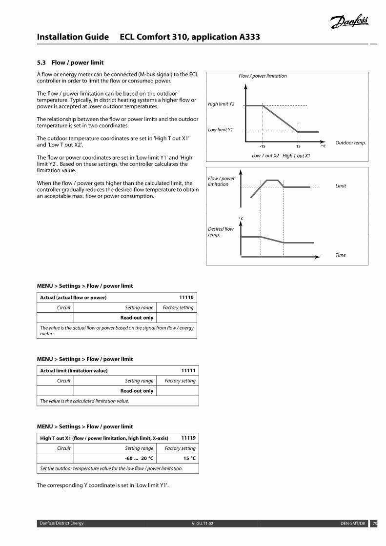
Installation Guide ECL Comfort 310, application A333
5.3 Flow / power limit
A flow or energy meter can be connected (M-bus signal) to the ECLcontroller in order to limit the flow or consumed power.
The flow / power limitation can be based on the outdoortemperature. Typically, in district heating systems a higher flow orpower is accepted at lower outdoor temperatures.
The relationship between the flow or power limits and the outdoortemperature is set in two coordinates.
The outdoor temperature coordinates are set in 'High T out X1'and 'Low T out X2'.
The flow or power coordinates are set in 'Low limit Y1' and 'Highlimit Y2'. Based on these settings, the controller calculates thelimitation value.
When the flow / power gets higher than the calculated limit, thecontroller gradually reduces the desired flow temperature to obtainan acceptable max. flow or power consumption.
Flow / power limitation
High limit Y2
Low limit Y1
° C15-15Outdoor temp.
Low T out X2 High T out X1
Flow / powerlimitation Limit
Desired flowtemp.
° C
Time
MENU > Settings > Flow / power limit
Actual (actual flow or power) 11110
Circuit Setting range Factory setting
Read-out only
The value is the actual flow or power based on the signal from flow / energymeter.
MENU > Settings > Flow / power limit
Actual limit (limitation value) 11111
Circuit Setting range Factory setting
Read-out only
The value is the calculated limitation value.
MENU > Settings > Flow / power limit
High T out X1 (flow / power limitation, high limit, X-axis) 11119
Circuit Setting range Factory setting
-60 ... 20 °C 15 °C
Set the outdoor temperature value for the low flow / power limitation.
The corresponding Y coordinate is set in 'Low limit Y1'.
Danfoss District Energy VI.GU.T1.02 DEN-SMT/DK 79
Installation Guide ECL Comfort 310, application A333
MENU > Settings > Flow / power limit
Low limit Y1 (flow / power limitation, low limit, Y-axis) 11117
Circuit Setting range Factory setting
0.0 ... 999.9 l/h 999.9 l/h
Set the flow / power limitation referring to the outdoor temperature set in'High T out X1'.
The corresponding X coordinate is set in 'High T out X1'.
The limitation function can overrule the set 'Temp. min' of the desiredflow temperature.
MENU > Settings > Flow / power limit
Low T out X2 (flow / power limitation, low limit, X-axis) 11118
Circuit Setting range Factory setting
-60 ... 20 °C -15 °C
Set the outdoor temperature value for the high flow / power limitation.
The corresponding Y coordinate is set in 'High limit Y2'.
MENU > Settings > Flow / power limit
High limit Y2 (flow / power limitation, high limit, Y-axis) 11116
Circuit Setting range Factory setting
0.0 ... 999.9 l/h 999.9 l/h
Set the flow / power limitation referring to the outdoor temperature setin 'Low T out X2'.
The corresponding X coordinate is set in 'Low T out X2'.
MENU > Settings > Flow / power limit
Adapt. time (adaptation time) 11112
Circuit Setting range Factory setting
1 OFF / 1 ... 50 sec OFF
Controls how fast the flow / power limitation adapts to the desiredlimitation.
OFF: The control function is not influenced by the"Adapt. time".
Low value: The desired temperature is adapted slowly.
High value: The desired temperature is adapted quickly.
If the ‘Adapt. time’ is too high, there is a risk of unstable control.
MENU > Settings > Flow / power limit
Filter constant 11113
Circuit Setting range Factory setting
1 ... 50 10
The actual filter dampens the flow / power input data by the set factor.
1: Minor dampening (low filter constant)
50: Major dampening (high filter constant)
80 DEN-SMT/DK VI.GU.T1.02 Danfoss District Energy
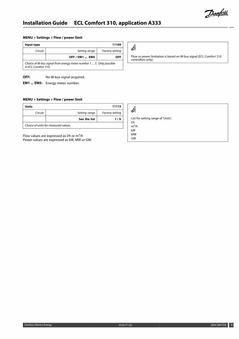
Installation Guide ECL Comfort 310, application A333
MENU > Settings > Flow / power limit
Input type 11109
Circuit Setting range Factory setting
OFF / EM1 ... EM5 OFF
Choice of M-bus signal from energy meter number 1 ... 5. Only possiblein ECL Comfort 310.
OFF: No M-bus signal acquired.
EM1 ... EM5: Energy meter number.
Flow or power limitation is based on M-bus signal (ECL Comfort 310controllers only).
MENU > Settings > Flow / power limit
Units 11115
Circuit Setting range Factory setting
See the list l / h
Choice of units for measured values.
Flow values are expressed as l/h or m³/hPower values are expressed as kW, MW or GW.
List for setting range of 'Units':l/hm³/hkWMWGW
Danfoss District Energy VI.GU.T1.02 DEN-SMT/DK 81

Installation Guide ECL Comfort 310, application A333
5.4 Optimization
MENU > Settings > Optimization
Auto saving (saving temp. dependent on outdoor temp.) 11011
Circuit Setting range Factory setting
OFF / -29 ... 10 °C -15 °C
Below the set value for the outdoor temperature, the saving temperaturesetting has no influence. Above the set value for the outdoor temperature,the saving temperature relates to the actual outdoor temperature. Thefunction is relevant in district heating installations in order to avoid a bigchange in the desired flow temperature after a saving period.
OFF: The saving temperature does not depend on theoutdoor temperature.
-29 ... 10: The saving temperature depends on the outdoortemperature. When the outdoor temperature is above10 °C, the reduction is 100%. The lower the outdoortemperature, the less the temperature reduction. Whenthe outdoor temperature is below the set limit, there isno temperature reduction.
The comfort and the saving temperatures are set in the displayoverviews. The difference between the comfort and the savingtemperature is considered to be 100%. Depending on the outdoortemperature, the percentage value can be lower according to theset value in ‘Auto saving’.
Reduction
100%
0%
-20 -10-29 0 2010 Outdoor temp. °C
Auto saving
Example:
Outdoor temp.: –5 °C
Desired room temp. in Comfort mode: 22 °C
Desired room temp. in Saving mode: 16 °C
Setting in ‘Auto saving’: –15 °C
The drawing above illustrates that the reduction percentage at anoutdoor temperature of –5 °C is 40%.
The difference between Comfort and Saving temperature is (22–16)= 6 degrees.
40% of 6 degrees = 2.4 degrees
The ‘Auto saving’ temperature is corrected to (22–2.4) = 19.6 °C.
MENU > Settings > Optimization
Boost 11012
Circuit Setting range Factory setting
OFF / 1 ... 99% OFF
Shortens the heating-up period by increasing the desired flow temperatureby the percentage you set.
OFF: The boost function is not active.
1-99%: The desired flow temperature is increased temporarilywith the set percentage.
In order to shorten the heating-up period after a savingtemperature period, the desired flow temperature can be increasedtemporarily (max. 1 hour). At optimizing the boost is active in theoptimization period ('Optimizer').
If a room temperature sensor or an ECA 30 / 31 is connected, theboost stops when the room temperature is reached.
82 DEN-SMT/DK VI.GU.T1.02 Danfoss District Energy

Installation Guide ECL Comfort 310, application A333
MENU > Settings > Optimization
Ramp (reference ramping) 11013
Circuit Setting range Factory setting
OFF / 1 ... 99 m OFF
The time (minutes) in which the desired flow temperature increasesgradually to avoid load peaks in the heat supply.
OFF: The ramping function is not active.
1-99m: The desired flow temperature is increased gradually withthe set minutes.
In order to avoid load peaks in the supply network, the flowtemperature can be set to increase gradually after a period withsaving temperature. This causes the valve to open gradually.
Temp. °C
Time (min.)
Ramping time
MENU > Settings > Optimization
Optimizer (optimizing time constant) 11014
Circuit Setting range Factory setting
OFF / 10 ... 59 OFF
Optimizes the start and stop times for the comfort temperature period toobtain the best comfort at the lowest energy consumption.The lower the outdoor temperature, the earlier the heating cut-in. The lowerthe outdoor temperature, the later the heating cut-out.The optimized heating cut-out time can be automatic or disabled. Thecalculated start and stop times are based on the setting of the optimizingtime constant.
Adjust the optimizing time constant.
The value consists of a two digit number. The two digits have thefollowing meaning (digit 1 = Table I, digit 2 = Table II).
OFF: No optimization. The heating starts and stops at thetimes set in the schedule.
10 ... 59: See tables I and II.
Table I:
Left digit Heat accumulation of thebuilding
System type
1- light
2- medium
3- heavy
Radiatorsystems
4- medium
5- heavy
Floor heatingsystems
Table II:
Right digit Dimensioning temperature Capacity
-0 -50 °C large
-1 -45 °C ·
· · ·
-5 -25 °C normal· · ·
-9 -5 °C small
Dimensioning temperature:The lowest outdoor temperature (usually determined by your systemdesigner in connectionwith the design of the heating system) at whichthe heating system can maintain the designed room temperature.
ExampleThe system type is radiator, and the heat accumulation of the buildingis medium.The left digit is 2.The dimensioning temperature is -25 °C, and the capacity is normal.The right digit is 5.
Result:The setting is to be changed to 25.
Danfoss District Energy VI.GU.T1.02 DEN-SMT/DK 83

Installation Guide ECL Comfort 310, application A333
MENU > Settings > Optimization
Pre-stop (optimized stop time) 11026
Circuit Setting range Factory setting
OFF / ON ON
Disable the optimized stop time.
OFF: The optimized stop time is disabled.
ON: The optimized stop time is enabled.
Example: Optimization of Comfort from 07:00 - 22:00
Schedule
Pre-stop OFF
Pre-stop ON
07:00 22:00
Optimization start Optimization stop
MENU > Settings > Optimization
Total stop 11021
Circuit Setting range Factory setting
OFF / ON OFF
Decide whether youwant a total stop during the saving temperature period.
OFF: No total stop. The desired flow temperature is reducedaccording to:• desired room temperature in saving mode• auto saving
ON: The desired flow temperature is lowered to the set valuein ‘Frost pr.’ The circulation pump is stopped but frostprotection is still active, see 'P frost T'.
Desired flow temp. °C
Total stop = ON
‘Frost pr.’Time
Desired flow temp. °C
Total stop = OFF
‘Frost pr.’Time
The min. flow temperature limitation ('Temp. min.') is overruled when'Total stop' is ON.
84 DEN-SMT/DK VI.GU.T1.02 Danfoss District Energy

Installation Guide ECL Comfort 310, application A333
MENU > Settings > Optimization
Cut-out (limit for heating cut-out) 11179
Circuit Setting range Factory setting
OFF / 1 ... 50 °C 18 °C
The heating can be switched OFF when the outdoor temperature ishigher than the set value. The valve closes and after the post-runtime, the heating circulation pump stops. ‘Temp. min.’ will beoverruled.
The heating system switches ON again when the outdoortemperature and the accumulated (filtered) outdoor temperaturebecome lower than the set limit.
This function can save energy.
Set the value for outdoor temperature at which you want theheating system to switch OFF.
Temp. Actual outdoor temp. Accumulated outdoor temp.
18 °C
TimeHeating ON Heating OFF Heating ON
The heating cut-out is only active when the controller mode is inscheduled operation. When the cut-out value is set to OFF, there isno heating cut-out.
Danfoss District Energy VI.GU.T1.02 DEN-SMT/DK 85

Installation Guide ECL Comfort 310, application A333
5.5 Control parameters 1
The applications A333.1 and A333.2 control the motorized controlvalve M1 by means of 3-point control.
The application A333.3 controls the M1 by means of a 0 - 10 voltcontrol signal.
The motorized control valve M1 is opened gradually when the flowtemperature S3 is lower than the desired flow temperature andvice versa.
3-point controlled M1 (A333.1 and A333.2):
"Open" and "close" commands come from the electronic outputs ofthe ECL Comfort controller and control the position of M1.
The commands are expressed as "Arrow-up" (open) and"Arrow-down" (close) and displayed at the M1 symbol.
When the temperature at S3 is lower than the desired temperature,short open-commands come from the ECL Comfort controller inorder to open M1 more than the moment before. By this, the S3temperature aligns with the desired temperature.
Oppositely, when the temperature at S3 is higher than the desiredtemperature, short close-commands come from the ECL Comfortcontroller in order to close M1 more than the moment before.Again, the S3 temperature aligns with the desired temperature.
Neither open-commands nor close-commands will come as long asthe flow temperature corresponds to the desired temperature.
0 - 10 volt controlled M1 (A333.3):
A control voltage between 0 and 10 volt comes from the extensionmodule ECA 32 and controls the position of M1. The voltage isexpressed as a % value and displayed at the M1 symbol.
When the temperature at S3 is lower than the desired temperature,the control voltage is gradually increased in order to openM1morethan the moment before. By this, the S3 temperature aligns withthe desired temperature.
The control voltage remains on a fixed value as long as the flowtemperature corresponds to the desired temperature.
Oppositely, when the temperature at S3 is higher than the desiredtemperature, the control voltage is gradually decreased in order toclose M1more than the moment before. Again, the S3 temperaturealigns with the desired temperature.
86 DEN-SMT/DK VI.GU.T1.02 Danfoss District Energy

Installation Guide ECL Comfort 310, application A333
MENU > Settings > Control par. 1
Position (A333.2 / A333.3) Read-out
Circuit Setting range Factory setting
1 - *)
Position of themotorized control valve M1 is indicated as a% value.A 0 - 10 volt signal comes from a positionmeasuring in M1 and is applied toinput S11 (ECA 32). This input voltage is converted to the displayed% value.Access to conversion (scale) settings.
*) 2.0 volt = 0 %, 10.0 volt = 100 %
The position is measured by means of a 0 - 10 volt signal.The measured voltage must be converted to a position value bythe controller.
The following procedure sets up the conversion:Push the dial to see the graph and enter the value sets for the 2input voltages and related position values.Position value range: 0 … 100 %
The factory set voltage values (2.0 volt and 10.0 volt) can bechanged in the following two separatemenus "Low X" and "High X".
Factory settings: 2.0 , 0 (= 2.0 V / 0%) and 10.0,100 (= 10.0 V / 100%)
This means that the "Position" is 0 % at 2.0 V and 100 % at 10.0 V.Typically, the higher the voltage, the higher the displayed position.
X = Volt
Y = Position
This scaling menu is always displayed, regardless a position signalis applied.The position is indicated as 0 when the position signal is not applied.
MENU > Settings > Control par. 1
Filter constant (A333.2 / A333.3) 15113
Circuit Setting range Factory setting
1 1 - 250 2
The filter constant dampens the position signal from the positionmeasurement in M1 in order to make a stable read-out.
1: Minor dampening (low filter constant)
250: Major dampening (high filter constant)
Danfoss District Energy VI.GU.T1.02 DEN-SMT/DK 87
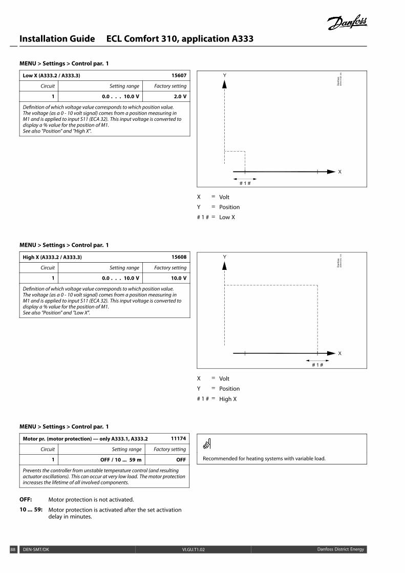
Installation Guide ECL Comfort 310, application A333
MENU > Settings > Control par. 1
Low X (A333.2 / A333.3) 15607
Circuit Setting range Factory setting
1 0.0 . . . 10.0 V 2.0 V
Definition of which voltage value corresponds to which position value.The voltage (as a 0 - 10 volt signal) comes from a position measuring inM1 and is applied to input S11 (ECA 32). This input voltage is converted todisplay a % value for the position of M1.See also "Position" and "High X".
X = Volt
Y = Position
# 1 # = Low X
MENU > Settings > Control par. 1
High X (A333.2 / A333.3) 15608
Circuit Setting range Factory setting
1 0.0 . . . 10.0 V 10.0 V
Definition of which voltage value corresponds to which position value.The voltage (as a 0 - 10 volt signal) comes from a position measuring inM1 and is applied to input S11 (ECA 32). This input voltage is converted todisplay a % value for the position of M1.See also "Position" and "Low X".
X = Volt
Y = Position
# 1 # = High X
MENU > Settings > Control par. 1
Motor pr. (motor protection)— only A333.1, A333.2 11174
Circuit Setting range Factory setting
1 OFF / 10 ... 59 m OFF
Prevents the controller from unstable temperature control (and resultingactuator oscillations). This can occur at very low load. Themotor protectionincreases the lifetime of all involved components.
OFF: Motor protection is not activated.
10 ... 59: Motor protection is activated after the set activationdelay in minutes.
Recommended for heating systems with variable load.
88 DEN-SMT/DK VI.GU.T1.02 Danfoss District Energy

Installation Guide ECL Comfort 310, application A333
MENU > Settings > Control par. 1
Xp (proportional band) 11184
Circuit Setting range Factory setting
1 5 ... 250 K 80 K
Set the proportional band. A higher value will result in a stable butslow control of the flow temperature.
MENU > Settings > Control par. 1
Tn (integration time constant) 11185
Circuit Setting range Factory setting
1 1 ... 999 s 30 s
Set a high integration time constant (in seconds) to obtain a slowbut stable reaction to deviations.
A low integration time constant will make the controller react fastbut with less stability.
MENU > Settings > Control par. 1
M run (running time of the motorized control valve)—only A333.1, A333.2
11186
Circuit Setting range Factory setting
1 5 ... 250 s 50 s
‘M run’ is the time in seconds it takes the controlled componentto move from fully closed to fully open position. Set the ‘M run’according to the examples or measure the running time by meansof a stop watch.
How to calculate the running time of a motorized control valveThe running time of the motorized control valve is calculated usingthe following methods:
Seated valves
Running time =Valve stroke (mm) x actuator speed (sec. / mm)
Example: 5.0 mm x 15 sec. / mm = 75 sec.
Rotating valves
Running time =Turning degrees x actuator speed (sec. / degr.)
Example: 90 degr. x 2 sec. / degr. = 180 sec.
MENU > Settings > Control par. 1
Nz (neutral zone) 11187
Circuit Setting range Factory setting
1 1 ... 9 K 3 K
Set the acceptable flow temperature deviation.
Set the neutral zone to a high value if you can accept a highvariation in flow temperature. When the actual flow temperatureis within the neutral zone, the controller does not activate themotorized control valve.
The neutral zone is symmetrical around the desired flow temperaturevalue, i.e. half the value is above and half the value is below thistemperature.
Danfoss District Energy VI.GU.T1.02 DEN-SMT/DK 89

Installation Guide ECL Comfort 310, application A333
MENU > Settings > Control par. 1
Min. act. time (min. activation time gear motor)—only A333.1, A333.2
11189
Circuit Setting range Factory setting
1 2 ... 50 3
The min. pulse period of 20 ms (milliseconds ) for activation of the gearmotor.
Setting example Value x 20 ms
2 40 ms
10 200 ms
50 1000 ms
The setting should be kept as high as acceptable to increase thelifetime of the actuator (gear motor).
90 DEN-SMT/DK VI.GU.T1.02 Danfoss District Energy
Installation Guide ECL Comfort 310, application A333
5.6 Control parameters, refill pump(s)
Control parameters for refill water pump(s), applicationsA333.2 / A333.3
The refill water pumps P3 / P4 can be speed controlled by means ofa 0 - 10 volt signal. The speed control signal comes from the outputM2 (terminals 60 and 56) on the ECA 32 module.
A desired pressure at S10 is set for the speed control procedure.The control voltage is expressed as a % value and displayed at theM2 symbol.
When the pressure at S10 gets too low, a refill pump (P3 or P4) isswitched ON.
The control voltage is gradually increased in order to increase thespeed of the refill water pump. By this, the pressure aligns withthe desired pressure.
The control voltage remains on a fixed value as long as the pressurecorresponds to the desired pressure.
The control voltage can be limited to a maximum and a minimum% value.
Sleep function:
In order to protect a refill pump against a too low speed, the "Sleepfunction" can be used.
When the speed control voltage for M2 gets lower than "Sleeplevel", the control voltage is commanded to 0 % after a period("Sleep mode time"). The refill pump stops.
After elapse of the "Sleep mode time" and a continued demand forrefill, the control voltage is commanded to "Wake-up level" andstarts the refill pump. A "Boost" can be added to the "Wake-uplevel".
Danfoss District Energy VI.GU.T1.02 DEN-SMT/DK 91

Installation Guide ECL Comfort 310, application A333
MENU > Settings > Control par., P refill
Pressure des. (A333.2 / A333.3) 11321
Circuit Setting range Factory setting
1 0.2 . . . 25.0 bar 3.0 bar
Setting of desired pressure at S10 in order to speed control the refill pump(s)P3 / P4.
0.2 - 25.0: Set the desired pressure at S10 (in bar)
X = Time
Y = Pressure
# 1 # = Pressure desired
# 2 # = Actual pressure
# 3 # = Pressure difference
# 4 # = Neutral zone, Nz
# 5 # = Refill water pump
# 6 # = Speed control signal (0 - 10 V)
The parameter "Pressure des." is also used in application A333.1 forsetting desired pressure for ON / OFF control of refill pump(s) P3 / P4.
MENU > Settings > Control par., P refill
Xp (proportional band) (A333.2 / A333.3) 13184
Circuit Setting range Factory setting
1 2 . . . 250 bar 25 bar
Set the proportional band for the control of the pressure at S10.
Low value: Controller reacts fast, but with less stability
High value: Controller reacts slow and with higher stability
92 DEN-SMT/DK VI.GU.T1.02 Danfoss District Energy

Installation Guide ECL Comfort 310, application A333
MENU > Settings > Control par., P refill
Tn (integration time ) (A333.2 / A333.3) 13185
Circuit Setting range Factory setting
1 1 . . . 999 sec 25 sec
Set the integration time for the control of the pressure at S10.
Low value: Controller reacts fast, but with less stability
High value: Controller reacts slow and with higher stability
MENU > Settings > Control par., P refill
Nz (neutral zone) (A333.2 / A333.3) 13187
Circuit Setting range Factory setting
1 0.1 . . . 2.0 bar 0.4 bar
Set the acceptable pressure deviation at S10.When the actual pressure is within the neutral zone, the controller doesnot change the refill pump speed.
Low value: A low variation in pressure is acceptable
High value: A high variation in pressure is acceptable
The neutral zone is symmetrical around the desired pressure value, i.e.half the value is above and half the value is below this pressure.
MENU > Settings > Control par., P refill
Td (Time derivative) (A333.2 / A333.3) 13197
Circuit Setting range Factory setting
1 0 . . . 250 sec 0 sec
The Td related function can avoid a too aggressive reaction in the speedcontrol procedure.
0: No influence
Low value: Minor influence
High value: Major influence
MENU > Settings > Control par., P refill
V out max. (A333.2 / A333.3) 13165
Circuit Setting range Factory setting
1 0 . . . 100 % 100 %
The output voltage for controlling the speed of the refill pump can be limitedto a maximum value.See also "V out min".
0 - 100: The value in % expresses the maximum voltagefor controlling the analogue output for the speedcontrol of the refill pump.
Example:
A setting of 60 % means that the output voltage will be 6 volt as amaximum.
The setting of "V.out min" has priority over "V.out max".
Danfoss District Energy VI.GU.T1.02 DEN-SMT/DK 93

Installation Guide ECL Comfort 310, application A333
MENU > Settings > Control par., P refill
V out min. (A333.2 / A333.3) 13167
Circuit Setting range Factory setting
1 0 . . . 100 % 0 %
The output voltage for controlling the speed of the refill pump can be limitedto a minimum value.See also "V out max".
0 - 100: The value in % expresses the maximum voltage forcontrolling the analogue output for the speed controlof the refill pump.
Example:
A setting of 15 % means that the output voltage will be 1.5 volt as aminimum.
The setting of "V.out min" has priority over "V.out max".
MENU > Settings > Control par., P refill
Sleep level (A333.2 / A333.3) 11331
Circuit Setting range Factory setting
1 OFF / 1 . . . 100 % 20 %
When the speed control signal gets below the "Sleep level" value, the speedwill be set to 0 (zero) % after elapse of "Sleep mode time".The refill pump stops (goes into sleep mode).The set value is also the speed level at a new refill procedure.This function protects the refill pump against low speed.See also: "Sleep mode time" and "Wake up level".
OFF: The sleep function is disabled
1 - 100: The sleep function is enabled
X = Time
Y = Speed control signal (0 - 10 V) (%))
# 1 # = Actual control signal
# 2 # = Sleep level
# 3 # = Wake-up level
# 4 # = Sleep mode time
MENU > Settings > Control par., P refill
Sleep mode time (A333.2 / A333.3) 11332
Circuit Setting range Factory setting
1 0 . . . 300 sec 10 sec
The "Sleep mode time" determines a delayed stop of the refill pump at toolow speed.See also: "Sleep level" and "Wake up level".
0 - 300: Set the sleep mode time (in seconds)
94 DEN-SMT/DK VI.GU.T1.02 Danfoss District Energy

Installation Guide ECL Comfort 310, application A333
MENU > Settings > Control par., P refill
Wake up level (A333.2 / A333.3) 11330
Circuit Setting range Factory setting
1 0 . . . 100 % 40 %
After elapse of the "Sleep mode" time and a continued refill demand, therefill water pump restarts with a speed level as the set value.See also: "Sleep level" and "Sleep mode time".
0 - 100: Set the restart speed level
MENU > Settings > Control par., P refill
Boost (A333.2 / A333.3) 11333
Circuit Setting range Factory setting
1 0 . . . 100 % 5 %
The "Wake-up level" can be increased with a % value.
0 - 100: Set the boost level
Example:
"Wake-up level" = 40 %
"Boost" = 15 %
Result: The increased "Wake-up level" = 40 x 1.15 = 46 %
Danfoss District Energy VI.GU.T1.02 DEN-SMT/DK 95

Installation Guide ECL Comfort 310, application A333
5.7 Control parameters, circulation pump(s)
Control parameters for circulation pump(s), applicationsA333.2 / A333.3
The circulation pumps P1 / P2 can be speed controlled by means ofa 0 - 10 volt signal. The speed control signal comes from the outputM3 (terminals 61 and 56) on the ECA 32 module.
A desired pressure difference between S9 and S10 is set for thespeed control procedure.
The control voltage is expressed as a % value and displayed at theM3 symbol.
When the pressure difference gets lower than the desired pressuredifference, the control voltage is gradually increased in order toincrease the speed of the circulation pump more than the momentbefore. By this, the pressure difference aligns with the desiredpressure difference.
The control voltage remains on a fixed value as long as the pressuredifference corresponds to the desired pressure difference.
The control voltage can be limited to a maximum. and a minimum% value.
MENU > Settings > Control par., P circ.
Pressure diff. (A333.2 / A333.3) 12322
Circuit Setting range Factory setting
1 0.1 . . . 5.0 bar 1.5 bar
Setting of desired pressure difference between S9 and S10 in order to speedcontrol the circulation pump(s) P1 / P2.
0.1 - 5.0: Set the desired pressure difference between S9 andS10 (in bar)
X = Time
Y = Pressure
# 1 # = Pressure diff., desired
# 2 # = Actual pressure difference
# 3 # = Neutral zone, Nz
# 4 # = Speed control signal (0 - 10 V)
96 DEN-SMT/DK VI.GU.T1.02 Danfoss District Energy

Installation Guide ECL Comfort 310, application A333
MENU > Settings > Control par., P circ.
Xp (proportional band) (A333.2 / A333.3) 12184
Circuit Setting range Factory setting
1 5 . . . 250 bar 10 bar
Set the proportional band for the control of the pressure difference betweenS9 and S10.
Low value: Controller reacts fast, but with less stability
High value: Controller reacts slow and with higher stability
MENU > Settings > Control par., P circ.
Tn (integration time ) (A333.2 / A333.3) 12185
Circuit Setting range Factory setting
1 1 . . . 999 sec 5 sec
Set the integration time for the control of the pressure difference betweenS9 and S10.
Low value: Controller reacts fast, but with less stability
High value: Controller reacts slow and with higher stability
MENU > Settings > Control par., P circ.
Nz (neutral zone) (A333.2 / A333.3) 12187
Circuit Setting range Factory setting
1 0.1 . . . 2.0 bar 1.0 bar
Set the acceptable pressure difference deviation.When the actual pressure difference is within the neutral zone, the controllerdoes not change the circulation pump speed.
Low value: A low variation in pressure is acceptable
High value: A high variation in pressure is acceptable
The neutral zone is symmetrical around the desired pressure differencevalue, i.e. half the value is above and half the value is below.
MENU > Settings > Control par., P circ.
Td (Time derivative) (A333.2 / A333.3) 12197
Circuit Setting range Factory setting
1 0 . . . 250 sec 0 sec
The Td related function can avoid a too aggressive reaction in the speedcontrol procedure.
0: No influence
Low value: Minor influence
High value: Major influence
Danfoss District Energy VI.GU.T1.02 DEN-SMT/DK 97
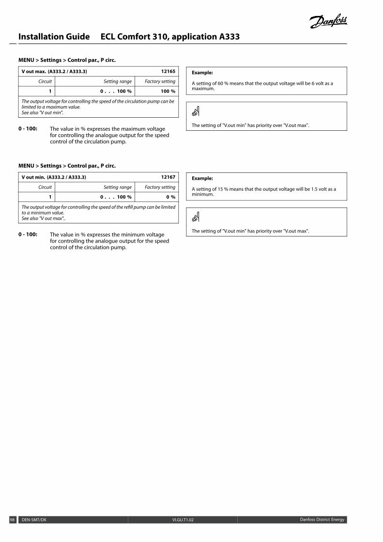
Installation Guide ECL Comfort 310, application A333
MENU > Settings > Control par., P circ.
V out max. (A333.2 / A333.3) 12165
Circuit Setting range Factory setting
1 0 . . . 100 % 100 %
The output voltage for controlling the speed of the circulation pump can belimited to a maximum value.See also "V out min".
0 - 100: The value in % expresses the maximum voltagefor controlling the analogue output for the speedcontrol of the circulation pump.
Example:
A setting of 60 % means that the output voltage will be 6 volt as amaximum.
The setting of "V.out min" has priority over "V.out max".
MENU > Settings > Control par., P circ.
V out min. (A333.2 / A333.3) 12167
Circuit Setting range Factory setting
1 0 . . . 100 % 0 %
The output voltage for controlling the speed of the refill pump can be limitedto a minimum value.See also "V out max"..
0 - 100: The value in % expresses the minimum voltagefor controlling the analogue output for the speedcontrol of the circulation pump.
Example:
A setting of 15 % means that the output voltage will be 1.5 volt as aminimum.
The setting of "V.out min" has priority over "V.out max".
98 DEN-SMT/DK VI.GU.T1.02 Danfoss District Energy

Installation Guide ECL Comfort 310, application A333
5.8 Pump control
The A333 application can operate with one or two circulationpumps, P1 or P1 / P2.
When operating with two circulation pumps, the pumps arecontrolled alternately, according to a time set-up.
When a pump is switched ON the controller is waiting for pressuredifference (S9 - S10) to build up.
If an acceptable pressure difference is not achieved, an alarm isgenerated and the ECL Comfort controller switches ON the otherpump.
If none of the pumps can come into operation (detected by meansof an unacceptable pressure difference), the alarm is activated andthe motorized control valve M1 closes (a safety function).
The alarm function is disabled if the "Alarm handling" (ID no. 11316) isset to OFF.Settings for pressure transmitter signal (0 - 10 volt) and conversion intopressure value are described in the section S7, S8, S9, S10 pressure.
MENU > Settings > Pump control
Pressure diff. 11322
Circuit Setting range Factory setting
1 0.1 . . . 5.0 bar 1.5 bar
Setting of acceptable pressure difference between S9 and S10 in order tofeed back that the circulation pump is working properly.
0.1 - 5.0: Set the desired pressure difference between S9 and S10(in bar)
MENU > Settings > Pump control
Chan.-over time (change-over time) 11314
Circuit Setting range Factory setting
1 OFF / 1 ... 99 s 15 sec
Setting of time to elapse between the pump stop command for one pumpand the start command for the other pump.The change-over time can ensure that a pump is stopped efficiently beforethe other pump starts.
OFF: One circulation pump in the application.
1 ... 99: Time for change-over.
X = Time
# 1 # = Change-over time (sec.)
Danfoss District Energy VI.GU.T1.02 DEN-SMT/DK 99

Installation Guide ECL Comfort 310, application A333
MENU > Settings > Pump control
Retry time 11310
Circuit Setting range Factory setting
1 OFF / 1... 99 m OFF
If an alarmhas been generated for the pump or alarms have been generatedfor both pumps, this setting will determine the time between the time of thealarm and the retry time for repeated pump start.
OFF: No retry time required after an alarm. The pump orpumps in question will not be restarted.
1 ... 99: After an alarm, the pump or pumps will be restartedafter the set time.
MENU > Settings > Pump control
Stab. time (stabilization time) 11313
Circuit Setting range Factory setting
1 1... 99 s 50 sec
Setting of max. time to elapse between pump start command and feedbackfrom differential pressure switch.If the differential pressure switch does not give feedback within the set time,the alarmwill be activated and the other pumpwill get a start command.
If the chosen stabilization time (‘Stab. time’) is too short, the activepump will stop immediately after the stabilization time has elapsed.
MENU > Settings > Pump control
Change, duration 11311
Circuit Setting range Factory setting
1 1 . . . 10 days 7 days
The number of days between shift of circulation pumps. The shift takes placeat the time set in 'Change time'.
X = Time
# 1 # = Change duration
100 DEN-SMT/DK VI.GU.T1.02 Danfoss District Energy
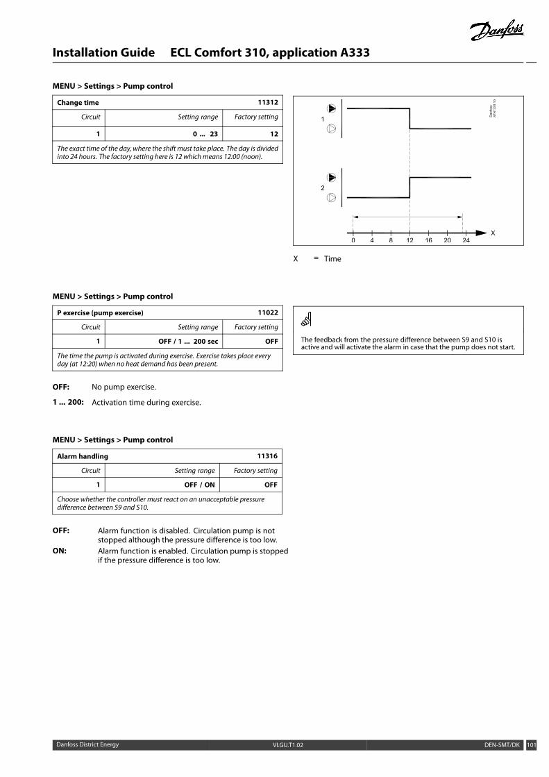
Installation Guide ECL Comfort 310, application A333
MENU > Settings > Pump control
Change time 11312
Circuit Setting range Factory setting
1 0 ... 23 12
The exact time of the day, where the shift must take place. The day is dividedinto 24 hours. The factory setting here is 12 whichmeans 12:00 (noon).
X = Time
MENU > Settings > Pump control
P exercise (pump exercise) 11022
Circuit Setting range Factory setting
1 OFF / 1 ... 200 sec OFF
The time the pump is activated during exercise. Exercise takes place everyday (at 12:20) when no heat demand has been present.
OFF: No pump exercise.
1 ... 200: Activation time during exercise.
The feedback from the pressure difference between S9 and S10 isactive and will activate the alarm in case that the pump does not start.
MENU > Settings > Pump control
Alarm handling 11316
Circuit Setting range Factory setting
1 OFF / ON OFF
Choose whether the controller must react on an unacceptable pressuredifference between S9 and S10.
OFF: Alarm function is disabled. Circulation pump is notstopped although the pressure difference is too low.
ON: Alarm function is enabled. Circulation pump is stoppedif the pressure difference is too low.
Danfoss District Energy VI.GU.T1.02 DEN-SMT/DK 101

Installation Guide ECL Comfort 310, application A333
5.9 Refill water
Leaks on the consumers side (secondary side) will result in fallingstatic pressure and thereby a poor supply of heating. A refill waterfunction can inject water to increase the static pressure.
The A333 application can monitor the static pressure and enablethe refill water function when the pressure is too low.
The pressure is measured by means of a pressure transmitter S10(giving a 0 - 10 volt signal in relation to the measured pressure).
The refill water function can operate with one or two refill waterpumps, P3 or P3 / P4. In addition a refill water valve V1 is controlled.
When operating with two refill water pumps, the pumps arecontrolled alternately, according to a time set-up.
When a too low pressure is detected the refill water pump isswitched ON and, after a set time, the ON-OFF valve is activated.
The controller awaits ("Time-out") the pressure at S10 to build up. Ifan acceptable pressure is not achieved, an alarm is generated andthe ECL Comfort controller switches OFF the pump in question.
The alarm function is disabled if the "Alarm handling" (ID no. 12316) isset to OFF.
Settings for pressure transmitter signal (0 - 10 volt) and conversioninto pressure value are described in the section "S7 - S10".
MENU > Settings > Refill water
Tiime Left Read-out
Circuit Setting range Factory setting
1 - -
Number of hours before a refill water pump change-over command takesplace.
102 DEN-SMT/DK VI.GU.T1.02 Danfoss District Energy
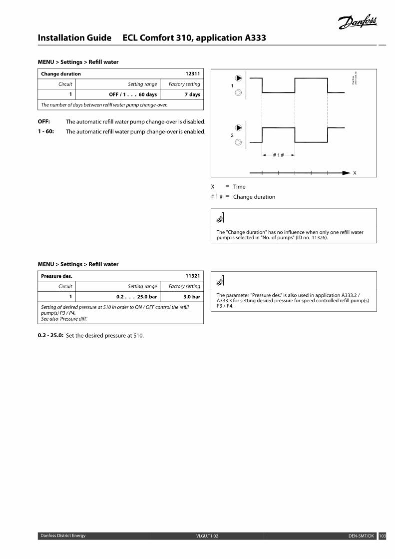
Installation Guide ECL Comfort 310, application A333
MENU > Settings > Refill water
Change duration 12311
Circuit Setting range Factory setting
1 OFF / 1 . . . 60 days 7 days
The number of days between refill water pump change-over.
OFF: The automatic refill water pump change-over is disabled.
1 - 60: The automatic refill water pump change-over is enabled.
X = Time
# 1 # = Change duration
The "Change duration" has no influence when only one refill waterpump is selected in "No. of pumps" (ID no. 11326).
MENU > Settings > Refill water
Pressure des. 11321
Circuit Setting range Factory setting
1 0.2 . . . 25.0 bar 3.0 bar
Setting of desired pressure at S10 in order to ON / OFF control the refillpump(s) P3 / P4.See also 'Pressure diff.'
0.2 - 25.0: Set the desired pressure at S10.
The parameter "Pressure des." is also used in application A333.2 /A333.3 for setting desired pressure for speed controlled refill pump(s)P3 / P4.
Danfoss District Energy VI.GU.T1.02 DEN-SMT/DK 103

Installation Guide ECL Comfort 310, application A333
MENU > Settings > Refill water
Pressure diff. 13322
Circuit Setting range Factory setting
1 0.1 . . . 5.0 bar 1.5 bar
Setting of the switching difference for themeasured pressure at S10.The difference is symmetrical around the 'Pressure des.'See also 'Pressure des.'
0.1 - 5.0: Set the desired switching difference related to thepressure at S10.
X = Time
Y = Pressure
# 1 # = Pressure desired
# 2 # = Actual pressure
# 3 # = Pressure difference
MENU > Settings > Refill water
Max. pressure 11318
Circuit Setting range Factory setting
1 0.0 . . . 40.0 bar 40.0 bar
Setting of the max. acceptable pressure at S10.When the pressure at S10 gets higher than set value, the release valve V2 isopened in order to reduce the pressure.See also "Max. press. diff."
0.0 - 40.0: Set the max. acceptable pressure at S10.
X = Time
Y = Pressure
# 1 # = Max. pressure
# 2 # = Actual pressure
# 3 # = Max. pressure difference
104 DEN-SMT/DK VI.GU.T1.02 Danfoss District Energy

Installation Guide ECL Comfort 310, application A333
MENU > Settings > Refill water
Max. pressure diff. 11319
Circuit Setting range Factory setting
1 -5.0 . . . -0.1 bar -0.5 bar
Setting of the pressure difference below "Max. pressure" to ensure anacceptable pressure in the heating system.When the pressure at S10 gets lower than the set difference below "Max.pressure", the release valve V2 is closed in order to stop reducing the pressure.See also "Max. pressure"
-5.0 - -0.1: Set the pressure difference related to "Max.pressure" at S10.
Danfoss District Energy VI.GU.T1.02 DEN-SMT/DK 105

Installation Guide ECL Comfort 310, application A333
MENU > Settings > Refill water
Time-out 11323
Circuit Setting range Factory setting
1 1 . . . 1000 sec 100 sec
Setting of the max. time for refill. The pressure, measured by S10, must beOK within the set time.If not, the refill water function stops and an alarm is activated.
X = Time
# 1 # = Pressure OK / not OK
# 2 # = Refill pump 3 or 4
# 3 # = Time-out
X = Time
# 1 # = Pressure OK / not OK
# 2 # = Refill pump 3 or 4
# 3 # = Time-out
# 4 # = Alarm
The "Time-out" function is disabled when "Alarm handling" (ID no.12316) is set to OFF.
106 DEN-SMT/DK VI.GU.T1.02 Danfoss District Energy

Installation Guide ECL Comfort 310, application A333
MENU > Settings > Refill water
P exercise (pump exercise) 11022
Circuit Setting range Factory setting
1 OFF / 1 ... 200 s OFF
The time the pump is activated during exercise. Exercise takes place everyday (at 12:00).
OFF: No pump exercise.
1 ... 200: Activation time during exercise.
The feedback from the pressure at S10 is active and will activate thealarm in case that the pump does not start.
MENU > Settings > Refill water
Valve delay 11325
Circuit Setting range Factory setting
1 0 ... 30 s 1 sec
Setting of the time for activation of the ON/OFF valve after start of the refillwater pump.
X = Time
Y = Pressure
# 1 # = Max. pressure
# 2 # = Actual pressure
# 3 # = Max. pressure difference
# 4 # = Valve delay
MENU > Settings > Refill water
No. of pumps 11326
Circuit Setting range Factory setting
1 1 / 2 1
Choose the number of refill water pumps in the system.
Danfoss District Energy VI.GU.T1.02 DEN-SMT/DK 107
Installation Guide ECL Comfort 310, application A333
MENU > Settings > Refill water
Alarm handling 12316
Circuit Setting range Factory setting
1 OFF / ON OFF
Choose whether the controller must react on an unacceptable pressure atS10.
OFF: Alarm function is disabled. Refill water pump is notstopped although the pressure is too low.
ON: Alarm function is enabled. Refill water pump is stoppedif the pressure difference is too low.
108 DEN-SMT/DK VI.GU.T1.02 Danfoss District Energy

Installation Guide ECL Comfort 310, application A333
5.10 Refill tank
A refill water storage tank can be controlled.
The water level at S12 is measured by means of a pressuretransmitter (giving a 0 - 10 volt signal in relation to the measuredpressure).
The water level is displayed in meters.
When the water level gets too low, the ON / OFF valve V3 is openedand fills refill water into the storage tank.
When the water level has reached an acceptable level, V3 is closed.
If an alarm is activated because of too high or too low level in therefill water storage tank, the refill pump(s) stop(s) and the valveV1 closes.
MENU > Settings > Refill tank
Level (A333.2 / A333.3) Read-out
Circuit Setting range Factory setting
1 - *)
Level of the water in the refill water storage tank is indicated as a valuein metersA 0 - 10 volt signal comes from a pressure transmitter and is applied to inputS12 (ECA 32). This input voltage is converted to the displayedmeter value.Access to conversion (scale) settings.
*) 2.0 volt = 0.0 m, 10.0 volt = 15.0 m
The water level is measured by means of a 0 - 10 voltsignal.
The measured voltage must be converted to a waterlevel value by the controller.
The following procedure sets up the conversion:Push the dial to see the graph and enter the value setsfor the 2 input voltages and related water level values.Water level value range: 0.0 … 20.0 m
The factory set voltage values (2.0 volt and 10.0 volt) canbe changed in the following two separate menus "LowX" and "High X".
Factory settings: 2.0 , 0 (= 2.0 V / 0.0 m) and 10.0 , 15.0 (=10.0 V / 15.0 m)
This means that the "Water level" is 0.0 m at 2.0 V and15.0 m at 10.0 V.
Typically, the higher the voltage, the higher thedisplayed water level.
X = Volt
Y = Meter
This scaling menu is always displayed, regardless a water level signalis applied.The water level is indicated as 0.0 m when the water level signal isnot applied.
Danfoss District Energy VI.GU.T1.02 DEN-SMT/DK 109

Installation Guide ECL Comfort 310, application A333
MENU > Settings > Refill tank
Filter constant 16113
Circuit Setting range Factory setting
1 1 - 250 4
The filter constant dampens the water level signal from the pressuretransmitter in order tomake a stable read-out and related functions.
1: Minor dampening (low filter constant)
250: Major dampening (high filter constant)
MENU > Settings > Refill tank
Low X (A333.2 / A333.3) 16607
Circuit Setting range Factory setting
1 0.0 . . . 10.0 V 2.0 V
Definition of which voltage value corresponds to which water level value.The voltage (as a 0 - 10 volt signal) comes from a pressure transmitter and isapplied to input S12 (ECA 32).This input voltage is converted to display a water level value (in meter).See also "Level" and "High X".
X = Volt
Y = Level
# 1 # = Low X
MENU > Settings > Refill tank
High X (A333.2 / A333.3) 16608
Circuit Setting range Factory setting
1 0.0 . . . 10.0 V 10.0 V
Definition of which voltage value corresponds to which water level value.The voltage (as a 0 - 10 volt signal) comes from a pressure transmitter and isapplied to input S12 (ECA 32).This input voltage is converted to display a water level value (in meter).See also "Level" and "Low X".
X = Volt
Y = Level
# 1 # = High X
110 DEN-SMT/DK VI.GU.T1.02 Danfoss District Energy
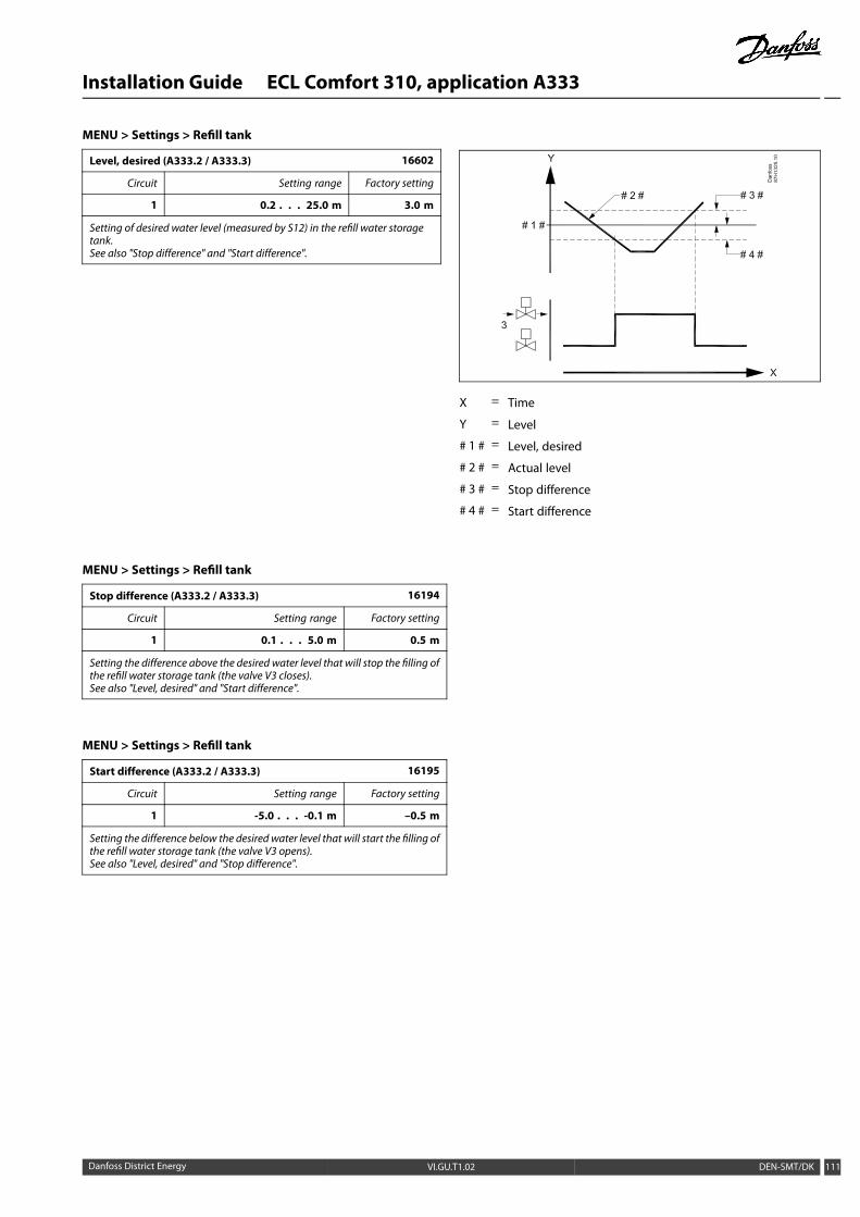
Installation Guide ECL Comfort 310, application A333
MENU > Settings > Refill tank
Level, desired (A333.2 / A333.3) 16602
Circuit Setting range Factory setting
1 0.2 . . . 25.0 m 3.0 m
Setting of desired water level (measured by S12) in the refill water storagetank.See also "Stop difference" and "Start difference".
X = Time
Y = Level
# 1 # = Level, desired
# 2 # = Actual level
# 3 # = Stop difference
# 4 # = Start difference
MENU > Settings > Refill tank
Stop difference (A333.2 / A333.3) 16194
Circuit Setting range Factory setting
1 0.1 . . . 5.0 m 0.5 m
Setting the difference above the desired water level that will stop the filling ofthe refill water storage tank (the valve V3 closes).See also "Level, desired" and "Start difference".
MENU > Settings > Refill tank
Start difference (A333.2 / A333.3) 16195
Circuit Setting range Factory setting
1 -5.0 . . . -0.1 m –0.5 m
Setting the difference below the desired water level that will start the filling ofthe refill water storage tank (the valve V3 opens).See also "Level, desired" and "Stop difference".
Danfoss District Energy VI.GU.T1.02 DEN-SMT/DK 111

Installation Guide ECL Comfort 310, application A333
5.11 Application
MENU > Settings > Application
Demand offset 11017
Circuit Setting range Factory setting
1 OFF / 1 ... 20 K OFF
The desired flow temperature in heating circuit 1 can be influenced by thedemand for a desired flow temperature from another controller (slave) oranother circuit.
OFF: The desired flow temperature in circuit 1 is notinfluenced by the demand of any other controller (slaveor circuit 2).
1 ... 20: The desired flow temperature is increased by the setvalue in ‘Demand offset’, if the demand of the slave /circuit 2 is higher.
Temp. Setting in‘Demand offset’
Des. flow temp.,circuit 1
Des. flow temp.,circuit 2
Time
The function of ‘Demand offset’ can compensate for heat lossesbetween master and slave controlled systems.
MENU > Settings > Application
Send desired T 11500
Circuit Setting range Factory setting
1 OFF / ON ON
When the controller acts as a slave controller in a master / slave system,information about the desired flow temperature can be sent to the mastercontroller via the ECL 485 bus.
OFF: Information about the desired flow temperature is notsent to the master controller.
ON: Information about the desired flow temperature is sentto the master controller.
In themaster controller, 'Demand offset' must be set to a value in orderto react on a desired flow temperature from a slave controller.
When the controller acts as a slave, its address must be 1, 2, 3 ... 9 inorder to send the desired temperature to the master (see the section‘Miscellaneous’, ‘Several controllers in the same system’).
MENU > Settings > Application
M exercise (valve exercise) 11023
Circuit Setting range Factory setting
OFF / ON OFF
Exercises the valve to avoid blocking in periods without heat demand.
OFF: The valve exercise is not active.
ON: The valve opens for 7 minutes and closes for 7 minutesevery third day at noon (12:00 hours).
The valve exercise is related to motorized control valves (MCV) inheating circuits.
112 DEN-SMT/DK VI.GU.T1.02 Danfoss District Energy

Installation Guide ECL Comfort 310, application A333
MENU > Settings > Application
DHW priority (closed valve / normal operation) 11052
Circuit Setting range Factory setting
OFF / ON OFF
The heating circuit can be closed when the controller acts as slave andwhenDHW heating / charging is active in the master.
OFF: The flow temperature control remains unchangedduring active DHW heating / charging in the mastercontroller.
ON: The valve in the heating circuit is closed* during activeDHW heating / charging in the master controller.* The desired flow temperature is set to the value set in‘Frost pr. T’
This setting must be considered if this controller is a slave.
The heating circuit can also be closed when the DHW heating is activein the same ECL controller.
MENU > Settings > Application
P frost T 11077
Circuit Setting range Factory setting
OFF / -10 ... 20 °C 2 °C
When the outdoor temperature is below the set temperature in ‘P frost T’,the controller automatically switches ON the circulation pump to protectthe system.
OFF: No frost protection.
-10 ... 20: The circulation pump is ON when the outdoortemperature is below the set value.
Under normal conditions, your system is not frost protected if yoursetting is below 0 °C or OFF.For water-based systems, a setting of 2 °C is recommended.
MENU > Settings > Application
P heat T (heat demand) 11078
Circuit Setting range Factory setting
5 ... 40 °C 20 °C
When the desired flow temperature is above the set temperature in ‘P heat T’,the controller automatically switches ON the circulation pump.
5 ... 40: The circulation pump is switched ON when the desiredflow temperature is above the set value.
The valve is fully closed as long as the pump is not switched on.
MENU > Settings > Application
Frost pr. T (frost protection temperature) 11093
Circuit Setting range Factory setting
5 ... 40 °C 10 °C
Set the desired flow temperature for example at heating cut-out, total stopetc. to protect the system against frost.
5 ... 40: Desired frost protection temperature.
Danfoss District Energy VI.GU.T1.02 DEN-SMT/DK 113

Installation Guide ECL Comfort 310, application A333
MENU > Settings > Application
Ext. input (external override) 11141
Circuit Setting range Factory setting
OFF / S1 ... S10 OFF
Choose the input for 'Ext. input' (external override). Bymeans of a switch thecontroller can be overridden to ‘Comfort’ or ‘Saving’ mode.
OFF: No inputs have been selected for external override.
S1 ... S10: Input selected for external override.
If S1... S6 is chosen as override input, the override switch must havegold-plated contacts.If S7 ... S10 is chosen as override input, the override switch can be astandard contact.
See the drawing for a connection example of an override switchto input S9.
The two drawings (override to comfort mode and override tosaving mode) show the functionality.
Choose only an unused input for override. If an already used input isapplied for override, the functionality of this input is also neglected.
See also ‘Ext. mode’.
Override to ‘Comfort’ mode
Time
Override to ‘Saving’ mode
Time
The result of override to 'Saving' mode depends on the setting in'Total stop'.Total stop = OFF: Heating reducedTotal stop = ON: Heating stopped
114 DEN-SMT/DK VI.GU.T1.02 Danfoss District Energy

Installation Guide ECL Comfort 310, application A333
MENU > Settings > Application
Ext. mode (external override mode) 11142
Circuit Setting range Factory setting
COMFORT / SAVING COMFORT
Choose external override mode.
The mode override can be activated for saving or comfort mode.For override, the controller mode must be scheduled mode.
SAVING: The controller is in saving mode when the overrideswitch is closed.
COMFORT: The controller is in comfort mode when the overrideswitch is closed.
See also ‘Ext. input’.
Danfoss District Energy VI.GU.T1.02 DEN-SMT/DK 115

Installation Guide ECL Comfort 310, application A333
5.12 Water meter
Applications A333.2 / A333.3
A water meter, F1, can measure the amount of refill water injectedinto the heating installation.
The water flow at F1 is measured by means of:
* a flow meter, giving pulses to "Pulse 1" on the ECA 32module or
* a flow meter, connected to the M-Bus terminals
The water amount is displayed in m3.
MENU > Settings > Water meter
CW consump. (A333.2 / A333.3) Read-out
Circuit Setting range Factory setting
1 - -
Amount of refill water injected into the heating installation.The displayed value is in m3.
MENU > Settings > Water meter
Pulse value (A333.2 / A333.3) 13513
Circuit Setting range Factory setting
1 0.1 . . . 1000.0 l 10.0 l
Setting of the value of each pulse from the water (flow) meter.This parameter is used when the water meter is connected to the "Pulse 1"on the ECA 32 module.
MENU > Settings > Water meter
Preset (A333.2 / A333.3) 13514
Circuit Setting range Factory setting
1 OFF / ON OFF
Is used for resetting the measured water consumption (registered by thecold water meter).Via theModbus communication a value can be preset to a defined value, forexample if the water meter is replaced.
OFF: Normal status.
ON: The registered amount of refill water is reset to 0 (zero).The setting returns to OFF.
116 DEN-SMT/DK VI.GU.T1.02 Danfoss District Energy

Installation Guide ECL Comfort 310, application A333
5.13 Flow meter
Applications A333.2 / A333.3
A flow meter, F2, can measure the circulating water flow in theheating installation.
The flow at F2 is measured by means of:
* a flow meter, giving a 0 - 10 volt signal and applied to S13on the ECA 32 module or
* a flow meter, giving pulses and applied to "Pulse 2" on theECA 32 module or
* a flow meter, connected to the M-Bus terminals.
The water flow can be displayed in l / h (liters / hour) or m3 / h(cubic meters / hour).
MENU > Settings > Flow meter
Actual (A333.2 / A333.3) Read-out
Circuit Setting range Factory setting
1 - *)
Actual flow in the heating installation.The displayed value is in l / h.Flowmeter F2 giving a 0 - 10 volt signal:The voltage signal is applied to the input S13 and is converted to thedisplayed flow value.Access to conversion (scale) settings.
*) 2.0 volt = 0 l/h, 10.0 volt = 1000 l/h
The flow is measured by means of a 0 - 10 volt signal.
Themeasured voltagemust be converted to a flow valueby the controller.
The following procedure sets up the conversion:Push the dial to see the graph and enter the value setsfor the 2 input voltages and related flow values.Flow value range: 0 … 1000 l/h.
The factory set voltage values (2.0 volt and 10.0 volt)can be changed in the following two separate menues"Low X" and "High X".
Factory settings: 2.0 , 0 (= 2.0 V / 0 l/h) and 10.0 , 1000(= 10,0 V / 1000 l/h)
This means that the "Flow" is 0.0 l/h at 2.0 V and 1000l/h at 10.0 V.
Typically, the higher the voltage, the higher thedisplayed flow.
X = Volt
Y = Liter / hour
This scaling menu is always displayed, regardless a flow signal isapplied.The flow is indicated as 0.0 l/h when the flow signal is not applied.
Danfoss District Energy VI.GU.T1.02 DEN-SMT/DK 117
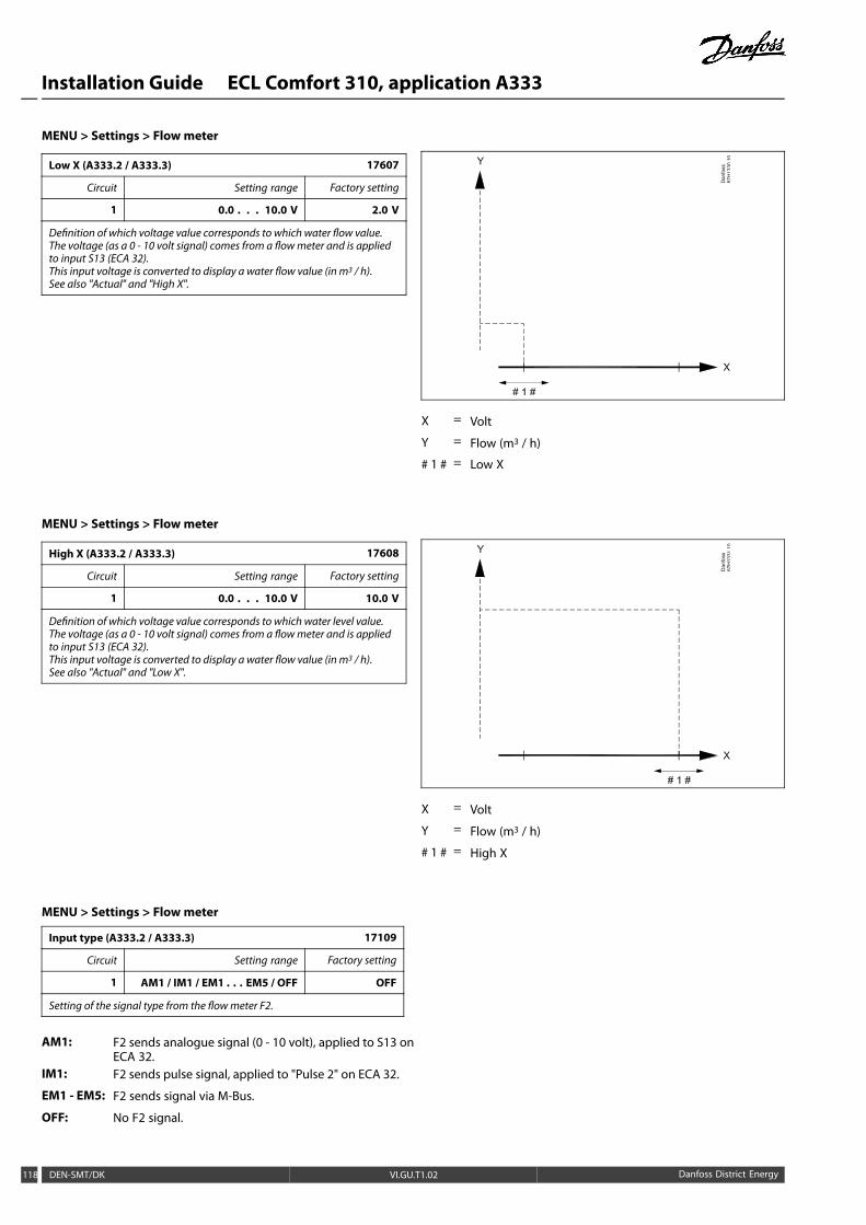
Installation Guide ECL Comfort 310, application A333
MENU > Settings > Flow meter
Low X (A333.2 / A333.3) 17607
Circuit Setting range Factory setting
1 0.0 . . . 10.0 V 2.0 V
Definition of which voltage value corresponds to which water flow value.The voltage (as a 0 - 10 volt signal) comes from a flowmeter and is appliedto input S13 (ECA 32).This input voltage is converted to display a water flow value (in m3 / h).See also "Actual" and "High X".
X = Volt
Y = Flow (m3 / h)
# 1 # = Low X
MENU > Settings > Flow meter
High X (A333.2 / A333.3) 17608
Circuit Setting range Factory setting
1 0.0 . . . 10.0 V 10.0 V
Definition of which voltage value corresponds to which water level value.The voltage (as a 0 - 10 volt signal) comes from a flowmeter and is appliedto input S13 (ECA 32).This input voltage is converted to display a water flow value (in m3 / h).See also "Actual" and "Low X".
X = Volt
Y = Flow (m3 / h)
# 1 # = High X
MENU > Settings > Flow meter
Input type (A333.2 / A333.3) 17109
Circuit Setting range Factory setting
1 AM1 / IM1 / EM1 . . . EM5 / OFF OFF
Setting of the signal type from the flowmeter F2.
AM1: F2 sends analogue signal (0 - 10 volt), applied to S13 onECA 32.
IM1: F2 sends pulse signal, applied to "Pulse 2" on ECA 32.
EM1 - EM5: F2 sends signal via M-Bus.
OFF: No F2 signal.
118 DEN-SMT/DK VI.GU.T1.02 Danfoss District Energy
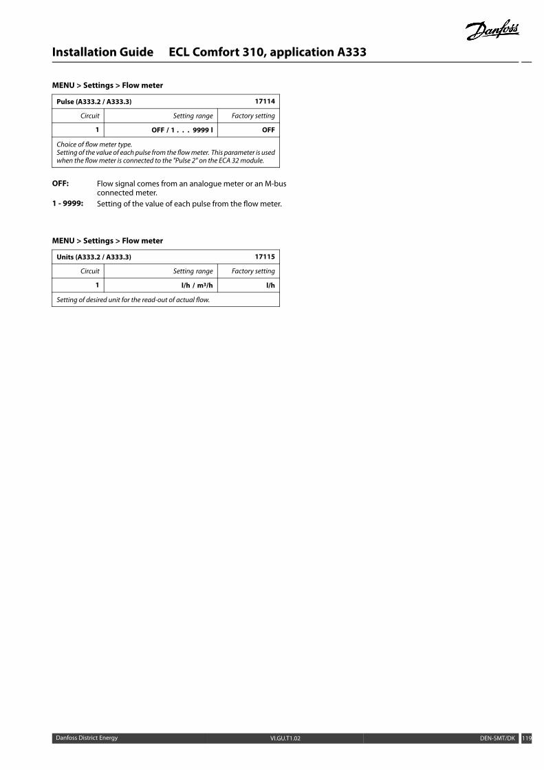
Installation Guide ECL Comfort 310, application A333
MENU > Settings > Flow meter
Pulse (A333.2 / A333.3) 17114
Circuit Setting range Factory setting
1 OFF / 1 . . . 9999 l OFF
Choice of flowmeter type.Setting of the value of each pulse from the flowmeter. This parameter is usedwhen the flowmeter is connected to the "Pulse 2" on the ECA 32module.
OFF: Flow signal comes from an analogue meter or an M-busconnected meter.
1 - 9999: Setting of the value of each pulse from the flow meter.
MENU > Settings > Flow meter
Units (A333.2 / A333.3) 17115
Circuit Setting range Factory setting
1 l/h / m3/h l/h
Setting of desired unit for the read-out of actual flow.
Danfoss District Energy VI.GU.T1.02 DEN-SMT/DK 119

Installation Guide ECL Comfort 310, application A333
5.14 S7, S8, S9, S10 pressure
Pressure measuring
The pressures at S7, S8, S9 and S10 are measured by means ofpressure transmitters, all giving a 0 - 10 volt signal in relation tothe measured pressure.
Alternatively, other pressure transmitter types can give a 4 - 20 mAsignal in relation to the measured pressure.
As described in the section "Electrical connections, Pt 1000temperature sensors and signals" the 4 - 20mA can be sent through(for example) a 500 ohm resistor in order to convert the currentsignal to a voltage signal. (4 - 20 mA through a resistor of 500 ohmgives a voltage of 2 - 10 volt).
In this section the set-up procedure for pressure transmitters S7,S8, S9 and S10 is described commonly.
Overview, pressures in an A333 application:
Name: Place: Description:
S7 Primary supply for monitoring purpose
S8 Primary return for monitoring purpose
S9 Secondary flow mandatory for circulationpump control
S10 Secondary return mandatory for refill waterfunction and circulationpump control
120 DEN-SMT/DK VI.GU.T1.02 Danfoss District Energy
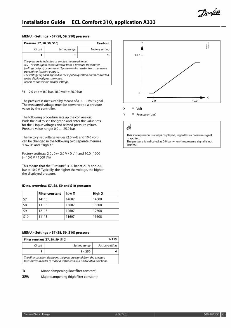
Installation Guide ECL Comfort 310, application A333
MENU > Settings > S7 (S8, S9, S10) pressure
Pressure (S7, S8, S9, S10) Read-out
Circuit Setting range Factory setting
1 - *)
The pressure is indicated as a value measured in bar.A 0 - 10 volt signal comes directly from a pressure transmitter(voltage output) or converted bymeans of a resistor from a pressuretransmitter (current output).The voltage signal is applied to the input in question and is convertedto the displayed pressure value.Access to conversion (scale) settings.
*) 2.0 volt = 0.0 bar, 10.0 volt = 20.0 bar
The pressure is measured bymeans of a 0 - 10 volt signal.The measured voltage must be converted to a pressurevalue by the controller.
The following procedure sets up the conversion:Push the dial to see the graph and enter the value setsfor the 2 input voltages and related pressure values.Pressure value range: 0.0 … 25.0 bar.
The factory set voltage values (2.0 volt and 10.0 volt)can be changed in the following two separate menues"Low X" and "High X".
Factory settings: 2.0 , 0 (= 2.0 V / 0 l/h) and 10.0 , 1000(= 10,0 V / 1000 l/h)
This means that the "Pressure" is 00 bar at 2.0 V and 2.,0bar at 10.0 V. Typically, the higher the voltage, the higherthe displayed pressure.
ID no. overview, S7, S8, S9 and S10 pressure:
Filter constant Low X High X
S7 14113 14607 14608
S8 13113 13607 13608
S9 12113 12607 12608
S10 11113 11607 11608
X = Volt
Y = Pressure (bar)
This scaling menu is always displayed, regardless a pressure signalis applied.The pressure is indicated as 0.0 bar when the pressure signal is notapplied.
MENU > Settings > S7 (S8, S9, S10) pressure
Filter constant (S7, S8, S9, S10) 1x113
Circuit Setting range Factory setting
1 1 - 250 4
The filter constant dampens the pressure signal from the pressuretransmitter in order tomake a stable read-out and related functions.
1: Minor dampening (low filter constant)
250: Major dampening (high filter constant)
Danfoss District Energy VI.GU.T1.02 DEN-SMT/DK 121

Installation Guide ECL Comfort 310, application A333
MENU > Settings > S7 (S8, S9, S10) pressure
Low X (S7, S8, S9, S10) 1x607
Circuit Setting range Factory setting
1 0.0 . . . 10.0 V 2.0 V
Definition of which voltage value corresponds to which pressure value.The voltage (as a 0 - 10 volt signal) comes from a pressure transmitter andis applied to input S7 (S8, S9, S10).This input voltage is converted to display a pressure value (in bar).See also "Pressure" and "High X".
X = Volt
Y = Pressure (bar)
# 1 # = Low X
MENU > Settings > S7 (S8, S9, S10) pressure
High X (S7, S8, S9, S10) 1x608
Circuit Setting range Factory setting
1 0.0 . . . 10.0 V 10.0 V
Definition of which voltage value corresponds to which pressure value.The voltage (as a 0 - 10 volt signal) comes from a pressure transmitter andis applied to input S7 (S8, S9, S10).This input voltage is converted to display a pressure value (in bar).See also "Pressure" and "Low X".
X = Volt
Y = Pressure (bar)
# 1 # = High X
122 DEN-SMT/DK VI.GU.T1.02 Danfoss District Energy

Installation Guide ECL Comfort 310, application A333
5.15 Alarm
The alarm function activates A1 (relay 6). The alarm relay canactivate a lamp, a horn, an input to an alarm transmitting device etc.
The alarm relay is activated
• as long as the alarm reason is present (automatic reset) or
• even the alarm reason has disappeared (manual reset)
Alarm, possibilities:
Name: Description: Reset:
Temp.monitor
Actual flow temperaturediffers from the desired flowtemperature.
Automatic
Refill tank(A333.2,A333.3)
Too low or too high water levelin refill water storage tank.
Manual
S7 . . . S10pressure
Too low or too high pressure. Automatic
Lowpressure
Too low pressure at S10. Automatic
Temperaturesensor input
Accidently break orshort-circuit of connectedtemperature sensor.
Manual
Resetting an alarm, in general:MENU > Alarm > Alarm overview: Look for alarm symbol in specificline.(Example: "3: Pump 1")Push dial
MENU > Alarm > Temp. monitor
Upper difference 11147
Circuit Setting range Factory setting
1 OFF / 1 ... 30 K OFF
The alarm is activated if the actual flow temperature increases more thanthe set difference (acceptable temperature difference above the desiredflow temperature). See also 'Delay'.
OFF: The alarm function is not active.
1 ... 30 K: The alarm function is active if the actual temperaturegets above the acceptable difference.
Flow temp. °C
Upper difference (setvalue)
Desired flow temp.
Time
MENU > Alarm > Temp. monitor
Lower difference 11148
Circuit Setting range Factory setting
1 OFF / 1 ... 30 K OFF
The alarm is activated if the actual flow temperature decreases more thanthe set difference (acceptable temperature difference below the desiredflow temperature). See also 'Delay'.
OFF: The alarm function is not active.
1 ... 30 K: The alarm function is active if the actual temperaturegets below the acceptable difference.
Flow temp. °C
Lower difference (setvalue)
Desired flow temp.
Time
Danfoss District Energy VI.GU.T1.02 DEN-SMT/DK 123

Installation Guide ECL Comfort 310, application A333
MENU > Alarm > Temp. monitor
Delay 11149
Circuit Setting range Factory setting
1 1 ... 99 m 10 m
If an alarm condition from either 'Upper difference' or 'Lower difference' ispresent for a longer time than the set delay (in min.), the alarm functionis activated.
1 ... 99 m: The alarm function will be activated if the alarmcondition remains after the set delay.
Temp.
Flow temp.
Alarm limit
Time
Delay
MENU > Alarm > Temp. monitor
Lowest temp. 11150
Circuit Setting range Factory setting
1 10 ... 50 °C 30 °C
The alarm function will not be activated if the desired flow / ducttemperature is lower than the set value.
If the cause of the alarm disappears, the alarm indication and outputalso disappear.
MENU > Alarm > Refill tank
Alarm high (A333.2 / A333.3) 16614
Circuit Setting range Factory setting
1 0.0 . . . 25.0 m 25.0 m
Alarm is activated when the refill water storage tank level (in meter) getshigher than the set value.See also: "Alarm low" (ID no. 16615) and "Alarm time-out" (ID no. 16617).
0.0 - 25.0: Set the high alarm level
When the "Alarm high" or "Alarm Low" alarm is activated:
* the alarm symbol appears in the display
* the refill water tank valve V3 closes
* the refill water valve V1 closes
* the refill water pump stops
If the alarm reason disappears:
* the alarm must be reset manually
Resetting an alarm:MENU > Alarm > Alarm overview > "5: Refill tank": Push dial
124 DEN-SMT/DK VI.GU.T1.02 Danfoss District Energy

Installation Guide ECL Comfort 310, application A333
MENU > Alarm > Refill tank
Alarm low (A333.2 / A333.3) 16615
Circuit Setting range Factory setting
1 0.0 . . . 25.0 m 0.0 m
Alarm is activated when the refill water storage tank level (in meter) getslower than the set value.See also: "Alarm high" (ID no. 16614) and "Alarm time-out" (ID no. 16617).
0.0 - 25.0: Set the low alarm level.
X = Time
Y = Level
# 1 # = Actual level
# 2 # = Alarm high
# 3 # = Alarm low
# 4 # = Alarm time-out
MENU > Alarm > Refill tank
Alarm time-out (A333.2 / A333.3) 16617
Circuit Setting range Factory setting
1 0 . . . 250 s 15 s
If an alarm condition from either 'Alarm high' or 'Alarm low' is present fora longer time than the set Alarm time-out (in seconds), the alarm functionis activated.See also: "Alarm high" (ID no. 16614) and "Alarm low" (ID no. 16615).
0 - 250: Set the time-out time.
X = Time
Y = Level
# 1 # = Actual level
# 2 # = Alarm high
# 3 # = Alarm low
# 4 # = Alarm time-out
ID no. overview for S7, S8, S9 and S10 alarm:
Alarm high Alarm low Alarm time-out
S7 14614 14615 14617
S8 13614 13615 13617
S9 12614 12615 12617
S10 11614 11615 11617
Danfoss District Energy VI.GU.T1.02 DEN-SMT/DK 125

Installation Guide ECL Comfort 310, application A333
MENU > Alarm > S7 (S8, S9, S10) pressure
Alarm high 1x614
Circuit Setting range Factory setting
1 0.0 . . . 25.0 bar 25.0 bar
Alarm is activated when the pressure (in bar) gets higher than the set value.
0.0 - 25.0: Set the high alarm level
MENU > Alarm > S7 (S8, S9, S10) pressure
Alarm low 1x615
Circuit Setting range Factory setting
1 0.0 . . . 25.0 bar 25.0 bar
Alarm is activated when the pressure (in bar) gets lower than the set value.
0.0 - 25.0: Set the low alarm level.
MENU > Alarm > S7 (S8, S9, S10) pressure
Alarm time-out 1x617
Circuit Setting range Factory setting
1 0 . . . 100 m 10 m
If an alarm condition from either 'Alarm high' or 'Alarm low' is present fora longer time than the set Alarm time-out (in minutes), the alarm functionis activated.
0 - 100: Set the time-out time.
MENU > Alarm > Low pressure
Alarm low 15615
Circuit Setting range Factorysetting
1 0.0 . . . 25.0 bar 25.0 bar
Alarm is activated when the pressure (in bar) at S10 gets lower than theset value.See also "Alarm time-out" (ID no. 15617).
0.0 - 25.0: Set the low alarm level
When the "Low pressure" alarm is activated:
* the alarm symbol appears in the display
* the control valve M1 closes
* the circulation pump stops
If the "Low pressure" alarm reason disappears:
* the alarm symbol disappears in the display
* the control valve M1 works normal
* the circulation pump starts
126 DEN-SMT/DK VI.GU.T1.02 Danfoss District Energy

Installation Guide ECL Comfort 310, application A333
MENU > Alarm > Low pressure
Alarm time-out 15617
Circuit Setting range Factory setting
1 0 . . . 250 s 10 s
If the alarm condition from 'Alarm low' is present for a longer time than theset Alarm time-out (in seconds), the alarm function is activated.See also "Alarm low" (ID no. 15615).
0 - 100: Set the time-out time.
Danfoss District Energy VI.GU.T1.02 DEN-SMT/DK 127

Installation Guide ECL Comfort 310, application A333
6.0 Common controller settings
6.1 Introduction to ‘Common controller settings’
Some general settings which apply to the entire controller arelocated in a specific part of the controller.
To enter ‘Common controller settings’:
Action: Purpose: Examples:
Choose ‘MENU’ in any circuit
Confirm
Choose the circuit selector at the topright corner in the display
Confirm
Choose ‘Common controller settings’
Confirm
Circuit selector
128 DEN-SMT/DK VI.GU.T1.02 Danfoss District Energy

Installation Guide ECL Comfort 310, application A333
6.2 Time & Date
It is only necessary to set the correct date and time in connectionwith the first use of the ECL Comfort controller or after a powerbreak of more than 72 hours.
The controller has a 24 hour clock.
Aut. daylight (Daylight saving time changeover)
YES: The controller’s built-in clock automatically changes + /- one hour on the standardized days for daylight savingtime changeover for Central Europe.
NO: You change manually between summer and winter timeby setting the clock backward or forward.
When controllers are connected as slaves in a master / slave system(via ECL 485 communication bus), they will receive ‘Time & Date’ fromthe master.
Danfoss District Energy VI.GU.T1.02 DEN-SMT/DK 129

Installation Guide ECL Comfort 310, application A333
6.3 Holiday
This section describes the function in general for the ECL Comfort210 / 310 series. The shown displays are typical and not applicationrelated. They might differ from the displays in your application.
There is a holiday program for each circuit and a holiday programfor the common controller.
Each holiday program contains one or more schedules. Eachschedule can be set to a start date and an end date. The set periodstarts on the start date at 00.00 and stops on the end date at 00.00.
Selectable modes are Comfort, Saving, Frost protection or Comfort7-23 (before 7 and after 23, the mode is scheduled).
How to set your holiday schedule:
Action: Purpose: Examples:
Choose ‘MENU’
Confirm
Choose the circuit selector at the topright corner in the display
Confirm
Choose a circuit or 'Common controllersettings'Heating
DHW
Common controller settings
Confirm
Go to ‘Holiday’
Confirm
Choose a schedule
Confirm
Confirm choice of mode selector
Choose mode
. Comfort
∙ Comfort 7–23 7-23
. Saving
∙ Frost protection
Confirm
Enter the start time first and then theend time
Confirm
Go to ‘Menu’
Confirm
Choose ‘Yes’ or ‘No’ in ‘Save’. Choosethe next schedule, if required
The holiday program in the ‘Common controller settings’ is valid forall circuits. The holiday program can also be set individually in theheating or DHW circuits.
The end date must be at least be one day later than the start date.
130 DEN-SMT/DK VI.GU.T1.02 Danfoss District Energy

Installation Guide ECL Comfort 310, application A333
The ECA 30 / 31 cannot override the holiday schedule of thecontroller temporarily.
However, it is possible to make use of the following options fromthe ECA 30 / 31 when the controller is in scheduled mode:
Day off
Holiday
Relaxing (extended comfort period)
Going out (extended saving period)
Energy-saving trick:Use 'Going out' (the extended saving period) for airing purposes (e.g.for ventilating the rooms by means of fresh air from open windows).
Connections and setup procedures for ECA 30 / 31:See section 'Miscellaneous'.
Quick guide "ECA 30 / 31 to override mode":1. Go to ECA MENU2. Move cursor to "Clock" symbol3. Select the "Clock" symbol4. Choose and select one of 4 override functions5. Below the override symbol: Set hours or date
Danfoss District Energy VI.GU.T1.02 DEN-SMT/DK 131

Installation Guide ECL Comfort 310, application A333
6.4 Input overview
This section describes the function in general for the ECL Comfort210 / 310 series. The shown displays are typical and not applicationrelated. They might differ from the displays in your application.
The input overview is located in the common controller settings.
This overview will always show you the actual temperatures in thesystem (read-only).
"Outdoor acc. T" means "Accummulated outdoor temperature" and isa calculated value in the ECL Comfort controller.
132 DEN-SMT/DK VI.GU.T1.02 Danfoss District Energy
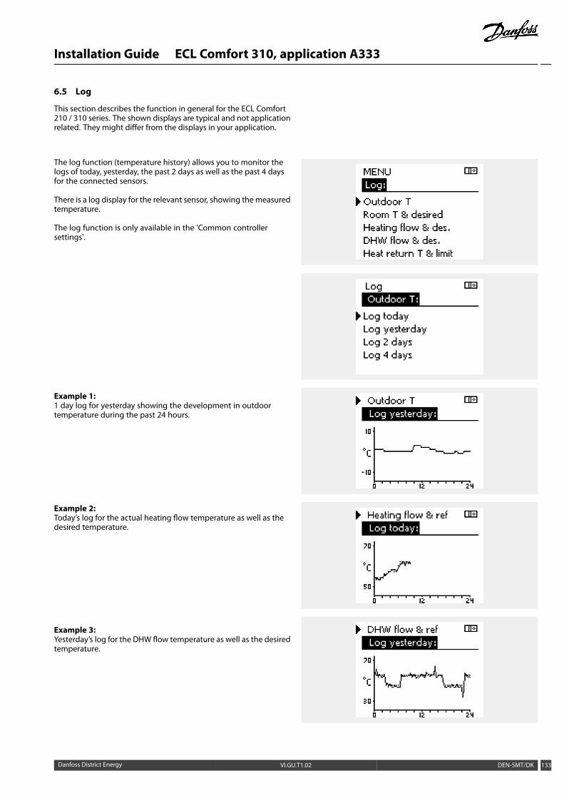
Installation Guide ECL Comfort 310, application A333
6.5 Log
This section describes the function in general for the ECL Comfort210 / 310 series. The shown displays are typical and not applicationrelated. They might differ from the displays in your application.
The log function (temperature history) allows you to monitor thelogs of today, yesterday, the past 2 days as well as the past 4 daysfor the connected sensors.
There is a log display for the relevant sensor, showing themeasuredtemperature.
The log function is only available in the 'Common controllersettings'.
Example 1:1 day log for yesterday showing the development in outdoortemperature during the past 24 hours.
Example 2:Today’s log for the actual heating flow temperature as well as thedesired temperature.
Example 3:Yesterday’s log for the DHW flow temperature as well as the desiredtemperature.
Danfoss District Energy VI.GU.T1.02 DEN-SMT/DK 133
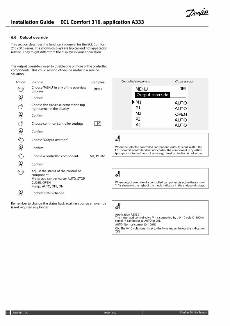
Installation Guide ECL Comfort 310, application A333
6.6 Output override
This section describes the function in general for the ECL Comfort210 / 310 series. The shown displays are typical and not applicationrelated. They might differ from the displays in your application.
The output override is used to disable one ormore of the controlledcomponents. This could among others be useful in a servicesituation.
Action: Purpose: Examples:
Choose 'MENU' in any of the overviewdisplays
Confirm
Choose the circuit selector at the topright corner in the display
Confirm
Choose common controller settings
Confirm
Choose 'Output override'
Confirm
Choose a controlled component M1, P1 etc.
Confirm
Adjust the status of the controlledcomponent:Motorized control valve: AUTO, STOP,CLOSE, OPENPump: AUTO, OFF, ON
Confirm status change
Remember to change the status back again as soon as an overrideis not required any longer.
Controlled components Circuit selector
When the selected controlled component (output) is not ‘AUTO’, theECL Comfort controller does not control the component in question(pump or motorized control valve e.g.). Frost protection is not active.
When output override of a controlled component is active the symbol‘ ! ’ is shown to the right of the mode indicator in the enduser displays.
Application A333.3:The motorized control valve M1 is controlled by a 0–10 volt (0–100%)signal. It can be set to AUTO or ON.AUTO: Normal control (0–100%)ON: The 0–10 volt signal is set to the %-value, set below the indication'ON'.
134 DEN-SMT/DK VI.GU.T1.02 Danfoss District Energy

Installation Guide ECL Comfort 310, application A333
6.7 Key functions
New application Erase application:Removes the existing application. Assoon as the ECL key is inserted, anotherapplication can be chosen.
Application Gives an overview over the applicationand its subtypes of the ECL key inquestion.
Factory setting System settings:System settings are, among others,communication set-up, displaybrightness etc.
User settings:User settings are, among others, desiredroom temperature, desired DHWtemperature, schedules, heat curve,limitation values etc.
Go to factory:Restores the factory settings.
Copy To:Copy direction
System settings
User settings
Start copying
A more detailed description of how to use the individual ‘Keyfunctions’ can also be seen in ‘Inserting the ECL application key’.
Key inserted / not inserted, description:
ECL Comfort 210 / 310, controller versions lower than 1.36:
- Take out the application key; for 20 minutessettings can be changed.
- Power up the controller without theapplication key inserted; for 20 minutessettings can be changed.
ECL Comfort 210 / 310, controller versions 1.36 and up:
- Take out the application key; for 20 minutessettings can be changed.
- Power up the controller without theapplication key inserted; settings cannot bechanged.
Danfoss District Energy VI.GU.T1.02 DEN-SMT/DK 135

Installation Guide ECL Comfort 310, application A333
6.8 System
6.8.1 ECL version
In ‘ECL version’ you will always be able to find an overview of thedata related to your electronic controller.
Please have this information available if you need to contact yourDanfoss sales organization concerning the controller.
Information about your ECL Application Key can be found in ‘Keyfunctions’ and ‘ Key overview’.
Code no.: The Danfoss sales and order no.for the controller
Hardware: Hardware version of thecontroller
Software: Software version of thecontroller
Serial no.: Unique number for theindividual controller
Production week: Week no. and year (WW.YYYY)
Example, ECL version
6.8.2 Extension
ECL Comfort 310 only:‘Extension’ will offer you information about additional modules, ifany. An example could be the ECA 32 module.
6.8.3 Ethernet
The ECL Comfort 310 has a Modbus/TCP communication interfacethat allows the ECL controller to be connected to an Ethernetnetwork. This allows remote access to the ECL 310 controller basedon standard communication infrastructures.
In ‘Ethernet’ it is possible to set up the required IP addresses.
6.8.4 Portal config
The ECL Comfort 310 has a Modbus/TCP communication interfacethat allows the ECL controller to be connected to the internet.
Internet related parameters are set here.
6.8.5 M-bus config
The ECL Comfort 310 has an M-bus communication interface thatallows energy meters to be connected as slaves.
M-bus related parameters are set here.
6.8.6 Energy Meters
The ECL Comfort 310 allows communication with up to 5 energymeters via M-bus. In ‘Energy Meters’ data can be read the fromM-bus connected energy meters
136 DEN-SMT/DK VI.GU.T1.02 Danfoss District Energy

Installation Guide ECL Comfort 310, application A333
6.8.7 Raw input overview
Measured temperatures, input status and voltages are displayed.
In addition, a detection of malfunctions can be chosen for activatedtemperature inputs.
Monitoring the sensors:Choose the sensor which measures a temperature, for example theS5. When the dial is pressed, a magnifying glass appears in theselected line. The S5 temperature is now being monitored.
Alarm indication:Should the connection to the temperature sensor be disconnected,short-circuited or the sensor itself be defective, the alarm functionis activated.
In the "Raw input overview" an alarm symbol is shown at thedefective temperature sensor in question.
Resetting the alarm:Choose the sensor (S number) for which you want to clear thealarm. Press the dial. The magnifying glass and alarm symbolsdisappear.
When the dial is pressed again, the monitoring function isreactivated.
The temperature sensor inputs have a measuring range from -60 ...150 ° C.
If a temperature sensor or its connection breaks, the value indicationis " - - ".
If a temperature sensor or its connection is short-circuited, the valueindication is " - - - ".
6.8.8 Display
Backlight (display brightness) 60058
Circuit Setting range Factory setting
0 ... 10 5
Adjust the brightness of the display.
0: Weak backlight.
10: Strong backlight.
Contrast (display contrast) 60059
Circuit Setting range Factory setting
0 ... 10 3
Adjust the contrast of the display.
0: Low contrast.
10: High contrast.
Danfoss District Energy VI.GU.T1.02 DEN-SMT/DK 137

Installation Guide ECL Comfort 310, application A333
6.8.9 Communication
Modbus addr. 38
Circuit Setting range Factory setting
1 ... 247 1
Set the Modbus address if the controller is part of a Modbus network.
1 ... 247: Assign the Modbus address within the stated settingrange.
ECL 485 addr. (master / slave address) 2048
Circuit Setting range Factory setting
0 ... 15 15
This settting is relevant if more controllers are working in the same ECLComfort system (connected via the ECL 485 communication bus) and / orRemote Control Units (ECA 30 / 31) are connected.
0: The controller works as slave.The slave receives information about the outdoortemperature (S1), system time, and signal for DHWdemand in the master.
1 ... 9: The controller works as slave.The slave receives information about the outdoortemperature (S1), system time, and signal for DHWdemand in the master. The slave sends informationabout the desired flow temperature to the master.
10 ... 14: Reserved.
15: The ECL 485 communication bus is active.The controller is master. The master sends informationabout the outdoor temperature (S1) and system time.Connected Remote Control Units (ECA 30 / 31) arepowered.
The ECL Comfort controllers can be connected via the ECL 485communication bus to perform a larger system (the ECL 485communication bus can connect to max. 16 devices).
Each slave must be configured with its own address (1 ... 9).
However, more slaves can have the address 0 if they only have toreceive information about outdoor temperature and system time(listeners).
The total cable length of max. 200 m (all devices incl. the internal ECL485 communication bus) should not be exceeded.Cable lengths of more than 200 m may cause noise sensibility (EMC).
An ECL Comfort controller 210 / 310, type B (without display and dial)cannot be assigned to the address 0 (zero).
Service Pin 2150
Circuit Setting range Factory setting
0 / 1 0
This setting is only used in connection with set-up of Modbuscommunication.
Not applicable for the time being and reserved for future use!
138 DEN-SMT/DK VI.GU.T1.02 Danfoss District Energy
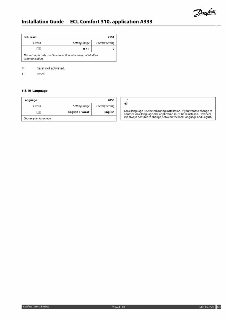
Installation Guide ECL Comfort 310, application A333
Ext. reset 2151
Circuit Setting range Factory setting
0 / 1 0
This setting is only used in connection with set-up of Modbuscommunication.
0: Reset not activated.
1: Reset.
6.8.10 Language
Language 2050
Circuit Setting range Factory setting
English / ‘Local’ English
Choose your language.
Local language is selected during installation. If you want to change toanother local language, the application must be reinstalled. However,it is always possible to change between the local language and English.
Danfoss District Energy VI.GU.T1.02 DEN-SMT/DK 139
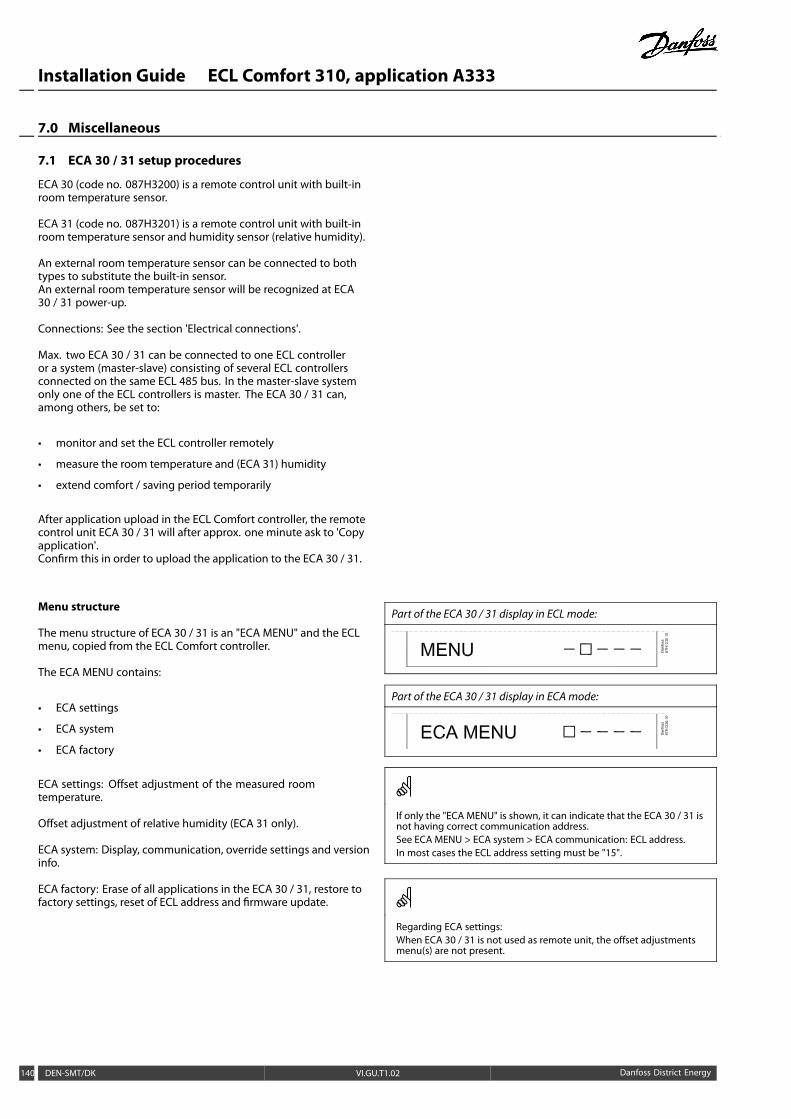
Installation Guide ECL Comfort 310, application A333
7.0 Miscellaneous
7.1 ECA 30 / 31 setup procedures
ECA 30 (code no. 087H3200) is a remote control unit with built-inroom temperature sensor.
ECA 31 (code no. 087H3201) is a remote control unit with built-inroom temperature sensor and humidity sensor (relative humidity).
An external room temperature sensor can be connected to bothtypes to substitute the built-in sensor.An external room temperature sensor will be recognized at ECA30 / 31 power-up.
Connections: See the section 'Electrical connections'.
Max. two ECA 30 / 31 can be connected to one ECL controlleror a system (master-slave) consisting of several ECL controllersconnected on the same ECL 485 bus. In the master-slave systemonly one of the ECL controllers is master. The ECA 30 / 31 can,among others, be set to:
• monitor and set the ECL controller remotely
• measure the room temperature and (ECA 31) humidity
• extend comfort / saving period temporarily
After application upload in the ECL Comfort controller, the remotecontrol unit ECA 30 / 31 will after approx. one minute ask to 'Copyapplication'.Confirm this in order to upload the application to the ECA 30 / 31.
Menu structure
The menu structure of ECA 30 / 31 is an "ECA MENU" and the ECLmenu, copied from the ECL Comfort controller.
The ECA MENU contains:
• ECA settings
• ECA system
• ECA factory
ECA settings: Offset adjustment of the measured roomtemperature.
Offset adjustment of relative humidity (ECA 31 only).
ECA system: Display, communication, override settings and versioninfo.
ECA factory: Erase of all applications in the ECA 30 / 31, restore tofactory settings, reset of ECL address and firmware update.
Part of the ECA 30 / 31 display in ECL mode:
Part of the ECA 30 / 31 display in ECAmode:
If only the "ECA MENU" is shown, it can indicate that the ECA 30 / 31 isnot having correct communication address.See ECA MENU > ECA system > ECA communication: ECL address.In most cases the ECL address setting must be "15".
Regarding ECA settings:When ECA 30 / 31 is not used as remote unit, the offset adjustmentsmenu(s) are not present.
140 DEN-SMT/DK VI.GU.T1.02 Danfoss District Energy
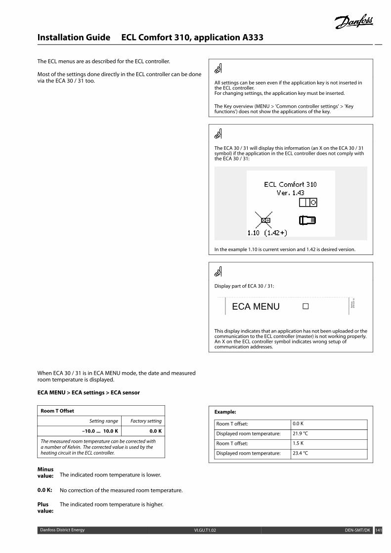
Installation Guide ECL Comfort 310, application A333
The ECL menus are as described for the ECL controller.
Most of the settings done directly in the ECL controller can be donevia the ECA 30 / 31 too. All settings can be seen even if the application key is not inserted in
the ECL controller.For changing settings, the application key must be inserted.
The Key overview (MENU > 'Common controller settings' > 'Keyfunctions') does not show the applications of the key.
The ECA 30 / 31 will display this information (an X on the ECA 30 / 31symbol) if the application in the ECL controller does not comply withthe ECA 30 / 31:
In the example 1.10 is current version and 1.42 is desired version.
Display part of ECA 30 / 31:
This display indicates that an application has not been uploaded or thecommunication to the ECL controller (master) is not working properly.An X on the ECL controller symbol indicates wrong setup ofcommunication addresses.
When ECA 30 / 31 is in ECA MENU mode, the date and measuredroom temperature is displayed.
ECA MENU > ECA settings > ECA sensor
Room T Offset
Setting range Factory setting
–10.0 ... 10.0 K 0.0 K
The measured room temperature can be corrected witha number of Kelvin. The corrected value is used by theheating circuit in the ECL controller.
Minusvalue: The indicated room temperature is lower.
0.0 K: No correction of the measured room temperature.
Plusvalue:
The indicated room temperature is higher.
Example:
Room T offset: 0.0 K
Displayed room temperature: 21.9 °C
Room T offset: 1.5 K
Displayed room temperature: 23.4 °C
Danfoss District Energy VI.GU.T1.02 DEN-SMT/DK 141

Installation Guide ECL Comfort 310, application A333
ECA MENU > ECA settings > ECA sensor
RH offset (ECA 31 only)
Setting range Factory setting
–10.0 ... 10.0 % 0.0 %
The measured relative humidity can be corrected with anumber of %-values. The corrected value is used by theapplication in the ECL controller.
Minusvalue: The indicated relative humidity is lower.
0.0 %: No correction of the measured relative humidity.
Plusvalue:
The indicated relative humidity is higher.
Example:
RH offset: 0.0 %
Displayed relative humidity: 43.4 %
RH offset: 3.5 %
Displayed relative humidity: 46.9 %
ECA MENU > ECA system > ECA display
Backlight (display brightness)
Setting range Factory setting
0 ... 10 5
Adjust the brightness of the display.
0: Weak backlight.
10: Strong backlight.
ECA MENU > ECA system > ECA display
Contrast (display contrast)
Setting range Factory setting
0 ... 10 3
Adjust the contrast of the display.
0: Low contrast.
10: High contrast.
ECA MENU > ECA system > ECA display
Use as remote
Setting range Factory setting
OFF / ON *)
ECA 30 / 31 can act as a simple or normal remote controlfor the ECL controller.
OFF: Simple remote control, no room temperature signal.
ON: Remote control, room temperature signal is available.
*): Differently, depending on chosen application.
When set to OFF: The ECA menu shows date and time.
When set to ON: The ECA menu shows date and room temperature(and for ECA 31 relative humidity).
142 DEN-SMT/DK VI.GU.T1.02 Danfoss District Energy

Installation Guide ECL Comfort 310, application A333
ECAMENU > ECA system > ECA communication
Slave addr. (Slave address)
Setting range Factory setting
A / B A
The setting of 'Slave addr.' is related to the setting 'ECAaddress' in the ECL controller.In the ECL controller it is selected fromwhich ECA 30 / 31unit the room temperature signal is received.
A: The ECA 30 / 31 has the address A.
B: The ECA 30 / 31 has the address B.
For installation of an application in an ECL Comfort 210 / 310 controllerthe 'Slave addr.' must be A.
If two ECA 30 / 31 are connected in the same ECL 485 bus system, the'Slave addr.' must be "A" in the one ECA 30 / 31 unit and "B" in the other.
ECAMENU > ECA system > ECA communication
Connection addr. (Connection address)
Setting range Factory setting
1 … 9 / 15 15
Setting of the address to which ECL controller thecommunication must run.
1 .. 9: Slave controllers.
15: Master controller.
An ECA 30 / 31 can in an ECL 485 bus system (master – slave) be set tocommunicate, one by one, with all addressed ECL controllers.
Example:
Connection addr. = 15: The ECA 30 / 31 communicates with theECL master controller.
Connection addr. = 2: The ECA 30 / 31 communicates with theECL controller with address 2.
There must be a master controller present in order to broadcast timeand date information.
An ECL Comfort controller 210 / 310, type B (without display and dial)cannot be assigned to the address 0 (zero).
Danfoss District Energy VI.GU.T1.02 DEN-SMT/DK 143

Installation Guide ECL Comfort 310, application A333
ECAMENU > ECA system > ECA override
Override addr. (Override address)
Setting range Factory setting
OFF / 1 … 9 / 15 OFF
The feature 'Override' (to extended comfort or savingperiod or holiday) must be addressed to the ECL controllerin question.
OFF: Override not possible.
1 .. 9: Address of slave controller for override.
15: Address of master controller for override.
Extended saving mode:
Extended comfort mode:
Holiday away from home:Override functions:
Holiday at home:
Override by means of settings in ECA 30 / 31 are cancelled if the ECLComfort controller goes into holiday mode or is changed to anothermode than scheduled mode.
The circuit in question for override in the ECL controller must be inscheduled mode.See also the parameter 'Override circuit'.
144 DEN-SMT/DK VI.GU.T1.02 Danfoss District Energy
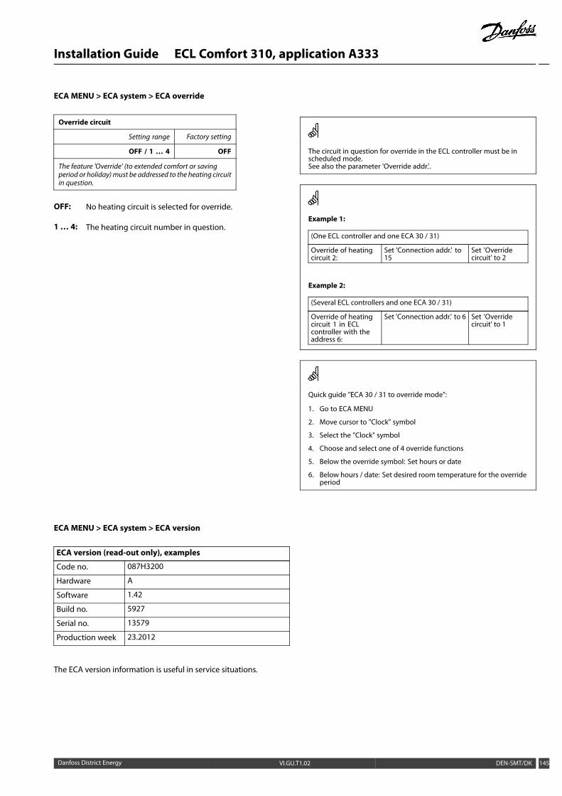
Installation Guide ECL Comfort 310, application A333
ECAMENU > ECA system > ECA override
Override circuit
Setting range Factory setting
OFF / 1 … 4 OFF
The feature 'Override' (to extended comfort or savingperiod or holiday)must be addressed to the heating circuitin question.
OFF: No heating circuit is selected for override.
1… 4: The heating circuit number in question.
The circuit in question for override in the ECL controller must be inscheduled mode.See also the parameter 'Override addr.'.
Example 1:
(One ECL controller and one ECA 30 / 31)
Override of heatingcircuit 2:
Set 'Connection addr.' to15
Set 'Overridecircuit' to 2
Example 2:
(Several ECL controllers and one ECA 30 / 31)
Override of heatingcircuit 1 in ECLcontroller with theaddress 6:
Set 'Connection addr.' to 6 Set 'Overridecircuit' to 1
Quick guide "ECA 30 / 31 to override mode":
1. Go to ECA MENU
2. Move cursor to "Clock" symbol
3. Select the "Clock" symbol
4. Choose and select one of 4 override functions
5. Below the override symbol: Set hours or date
6. Below hours / date: Set desired room temperature for the overrideperiod
ECA MENU > ECA system > ECA version
ECA version (read-out only), examples
Code no. 087H3200
Hardware A
Software 1.42
Build no. 5927
Serial no. 13579
Production week 23.2012
The ECA version information is useful in service situations.
Danfoss District Energy VI.GU.T1.02 DEN-SMT/DK 145

Installation Guide ECL Comfort 310, application A333
ECAMENU > ECA factory > ECA clear apps.
Erase all apps. (Erase all applications)
Erase all applications which are in the ECA 30 / 31.After erasing, the application can be uploaded again.
NO: The erase procedure is not done.
YES: The erase procedure is done (await 5 sec.).
After the erase procedure, a pop-up in the display indicates "Copyapplication". Choose "Yes".Hereafter the application is uploaded from the ECL controller. Anupload bar is shown.
ECA MENU > ECA factory > ECA default
Restore factory
The ECA 30 / 31 is set back to factory settings.
Affected settings by the restore procedure:
• Room T offset
• RH offset (ECA 31)
• Backlight
• Contrast
• Use as remote
• Slave addr.
• Connection addr.
• Override addr.
• Override circuit
• Override mode
• Override mode end time
NO: The restore procedure is not done.
YES: The restore procedure is done.
ECAMENU > ECA factory > Reset ECL addr.
Reset ECL addr. (Reset ECL address)
If none of the connected ECL Comfort controllers has the address15, the ECA 30 / 31 can set all connected ECL controllers on theECL 485 bus back to address 15.
NO: The reset procedure is not done.
YES: The reset procedure is done (await 10 sec.).
The ECL 485 bus related address of the ECL controller is found:MENU > 'Common controller settings' > 'System' > 'Communication' >'ECL 485 addr.'
The "Reset ECL addr." cannot be activated if one or more of theconnected ECL Comfort controllers has the address 15.
146 DEN-SMT/DK VI.GU.T1.02 Danfoss District Energy

Installation Guide ECL Comfort 310, application A333
ECAMENU > ECA factory > Update firmware
Update firmware
The ECA 30 / 31 can be updated with new firmware (software).The firmware comes with the ECL application key, when the keyversion is at least 2.xx.If no new firmware is available, a symbol of the application keyis displayed with an X.
NO: The updating procedure is not done.
YES: The updating procedure is done.
The ECA 30 / 31 automatically verifies if a new firmware is present onthe application key in the ECL Comfort controller.The ECA 30 / 31 is automatically updated at new application upload inthe ECL Comfort controller.The ECA 30 / 31 is not automatically updated when connected to anECL Comfort controller with uploaded application. A manual updateis always possible.
Quick guide "ECA 30 / 31 to override mode":
1. Go to ECA MENU
2. Move cursor to "Clock" symbol
3. Select the "Clock" symbol
4. Choose and select one of 4 override functions
5. Below the override symbol: Set hours or date
6. Below hours / date: Set desired room temperature for the overrideperiod
Danfoss District Energy VI.GU.T1.02 DEN-SMT/DK 147

Installation Guide ECL Comfort 310, application A333
7.2 Several controllers in the same system
When ECL Comfort controllers are interconnected by means ofthe ECL 485 communication bus (cable type: 2 x twisted pair), themaster controller will broadcast the following signals to the slavecontrollers:
• Outdoor temperature (measured by S1)
• Time and date
• DHW tank heating / charging activity
Furthermore, the master controller can receive information about:
• the desired flow temperature (demand) from slave controllers
• and (as from ECL controller version 1.48) DHW tank heating /charging activity in slave controllers
Situation 1:SLAVE controllers: How to make use of the outdoortemperature signal sent from the MASTER controller
The slave controllers only receive information about outdoortemperature and date / time.
SLAVE controllers:Change the factory set address from 15 to address 0.
• In , go to System > Communication > ECL 485 addr:
ECL 485 addr. (master / slave address) 2048
Circuit Setting range Choose
0 ... 15 0
In a system with MASTER / SLAVE controllers, only one MASTERcontroller with address 15 is allowed.
If by mistake more MASTER controllers are present in an ECL 485communication bus system, decide which controller is to be MASTER.Change the address in the remaining controllers. However, the systemwill operate but not be stable with more than one MASTER controller.
In the MASTER controller, the address in ‘ECL 485 addr. (master / slaveaddress)’, ID no. 2048, must always be 15.
148 DEN-SMT/DK VI.GU.T1.02 Danfoss District Energy

Installation Guide ECL Comfort 310, application A333
Situation 2:SLAVE controller: How to react on a DHW tank heating /charging activity sent from the MASTER controller
The slave receives information about a DHW tank heating /charging activity in the master controller and can be set to closethe selected heating circuit.
ECL controller versions 1.48 (as from August 2013):The master receives information about DHW tank heating /charging activity in the master controller itself and also slaves inthe system.This status is broadcasted to all ECL controllers in the system andeach heating circuit can be set to close the heating.
SLAVE controller:Set the desired function:
• In circuit 1 / circuit 2, go to ‘Settings’ > ‘Application’ >’DHWpriority’:
DHW priority (closed valve / normaloperation)
11052/ 12052
Circuit Setting range Choose
1 / 2 OFF / ON OFF / ON
OFF: The flow temperature control remains unchanged duringactive DHW heating / charging in the master / slavesystem.
ON: The valve in the heating circuit is closed during activeDHW heating / charging in the master / slave system.
Danfoss District Energy VI.GU.T1.02 DEN-SMT/DK 149

Installation Guide ECL Comfort 310, application A333
Situation 3:SLAVE controller: How tomake use of the outdoor temperaturesignal and send information about the desired flowtemperature back to the MASTER controller
The slave controller receives information about outdoortemperature and date / time. The master controller receivesinformation about the desired flow temperature from slavecontrollers with an address from 1 ... 9:
SLAVE controller:
• In , go to System > Communication > ECL 485 addr.
• Change the factory set address from 15 to an address (1 ... 9).Each slave must be configured with its own address.
ECL 485 addr. (master / slave address) 2048
Circuit Setting range Choose
0 ... 15 1 ... 9
Furthermore, each slave can send information about the desiredflow temperature (demand) in each circuit back to the mastercontroller.
SLAVE controller:
• In the circuit in question, go to Settings > Application > Senddesired T
• Choose ON or OFF.
Send desired T 11500/ 12500
Circuit Setting range Choose
1 / 2 OFF / ON ON or OFF
OFF: Information about the desired flow temperature is notsent to the master controller.
ON: Information about the desired flow temperature is sentto the master controller.
MASTER controller:
• In the circuit 1, go to Settings > Application > Demand offset
• Change OFF to a value (for example 5 K) which is added to thehighest demand (desired flow temperature) from the slaves.
Demand offset 11017
Circuit Setting range Choose
1 OFF / 1 ... 20 K 1 ... 20 K
In the MASTER controller, the address in ‘ECL 485 addr. (master / slaveaddress)’, ID no. 2048, must always be 15.
150 DEN-SMT/DK VI.GU.T1.02 Danfoss District Energy

Installation Guide ECL Comfort 310, application A333
7.3 Frequently asked questions
The definitions apply to the Comfort 210 as well as ECL Comfort310 series. Consequently, you might come across expressionsthat are not mentioned in your guide.
The time shown in the display is one hour off?See ‘Time and Date’.
The time shown in the display is not correct?The internal clock may have been reset, if there has been a powerbreak for more than 72 hours.Go to the 'Common controller settings' and 'Time & Date' to setthe correct time.
The ECL Application Key is lost?Switch the power off and on again to see the system type and thesoftware generation of the controller or go to 'Common controllersettings' >'Key functions' > 'Application'. The system type (e.g.TYPE A266.1) and the system diagram is displayed.Order a replacement from your Danfoss representative (e.g. ECLApplication Key A266).Insert the new ECL Application Key and copy your personalsettings from the controller to the new ECL Application Key, ifrequired.
The room temperature is too low?Make sure that the radiator thermostat does not limit the roomtemperature.If you still cannot obtain the desired room temperature byadjusting the radiator thermostats, the flow temperature is toolow. Increase the desired room temperature (display with desiredroom temperature). If this does not help, adjust the ‘Heat curve’(‘Flow temp.’).
The room temperature is too high during saving periods?Make sure that the min. flow temperature limitation ('Temp. min.')is not too high.
The temperature is unstable?Check that the flow temperature sensor is correctly connectedand in the right place. Adjust the control parameters ('Controlpar.').If the controller has a room temperature signal, see 'Room limit'.
The controller does not operate and the control valve isclosed?Check that the flow temperature sensor is measuring the correctvalue, see 'Daily use' or 'Input overview'.Check the influence from other measured temperatures.
How tomake an extra comfort period in the schedule?You can set an additional comfort period by adding new ‘Start’and ‘Stop’ times in ‘Schedule’.
How to remove a comfort period in the schedule?You can remove a comfort period by setting start and stop timesto the same value.
How to restore your personal settings?Please read the chapter concerning ‘Inserting the ECL ApplicationKey’.
How to restore the factory settings?Please read the chapter concerning ‘Inserting the ECL ApplicationKey’.
Why can’t the settings be changed?The ECL Application Key has been removed.
Danfoss District Energy VI.GU.T1.02 DEN-SMT/DK 151

Installation Guide ECL Comfort 310, application A333
Why can’t an application be selected when inserting the ECLapplication key into the controller?The actual application in the ECL Comfort controller must bedeleted before a new application (subtype) can be selected.
How to react on alarms?An alarm indicates that the system is not operating satisfactorily.Please contact your installer.
What does P and PI control mean?P control: Proportional control.By using a P control, the controller will change the flowtemperature proportional to the difference between a desiredand an actual temperature, e.g. a room temperature.A P control will always have an offset which not will disappearover time.
PI control: Proportional and Integrating control.A PI control does the same as a P control, but the offset willdisappear over time.A long ‘Tn’ will give a slow but stable control, and a short ‘Tn’ willresult in a fast control but with a higher risk of unstability.
152 DEN-SMT/DK VI.GU.T1.02 Danfoss District Energy
Installation Guide ECL Comfort 310, application A333
7.4 Definitions
The definitions apply to the Comfort 210 as well as ECL Comfort310 series. Consequently, you might come across expressionsthat are not mentioned in your guide.
Air duct temperatureTemperature measured in the air duct where the temperatureis to be controlled.
Alarm functionBased on the alarm settings, the controller can activate an output.
Anti-bacteria functionFor a defined period, the DHW temperature is increased in orderto neutralize dangerous bacteria, e.g. Legionella.
Balance temperatureThis setpoint is the basis for the flow / air duct temperature. Thebalance temperature can be adjusted by the room temperature,the compensation temperature and the return temperature. Thebalance temperature is only active if a room temperature sensoris connected.
Comfort operationNormal temperature in the system controlled by the schedule.During heating the flow temperature in the system is higher tomaintain the desired room temperature. During cooling the flowtemperature in the system is lower to maintain the desired roomtemperature.
Comfort temperatureTemperature maintained in the circuits during comfort periods.Normally during daytime.
Compensation temperatureA measured temperature influencing the flow temperaturereference / balance temperature.
Desired flow temperatureTemperature calculated by the controller on basis of the outdoortemperature and influences from the room and / or returntemperatures. This temperature is used as a reference for thecontrol.
Desired room temperatureTemperature which is set as the desired room temperature. Thetemperature can only be controlled by the ECL Comfort controllerif a room temperature sensor is installed.If a sensor is not installed, the set desired room temperaturehowever still influences the flow temperature.In both cases the room temperature in each room is typicallycontrolled by radiator thermostats / valves.
Desired temperatureTemperature based on a setting or a controller calculation.
Dew point temperatureTemperature at which the humidity in the air condensates.
DHW circuitThe circuit for heating the domestic hot water (DHW).
Factory settingsSettings stored on the ECL Application Key to simplify the set upof your controller the first time.
Flow temperatureTemperature measured in the flow at any time.
Danfoss District Energy VI.GU.T1.02 DEN-SMT/DK 153

Installation Guide ECL Comfort 310, application A333
Flow temperature referenceTemperature calculated by the controller on basis of the outdoortemperature and influences from the room and / or returntemperatures. This temperature is used as a reference for thecontrol.
Heat curveA curve showing the relationship between actual outdoortemperature and required flow temperature.
Heating circuitThe circuit for heating the room / building.
Holiday scheduleSelected days can be programmed to be in comfort, saving orfrost protection mode. Besides this, a day schedule with comfortperiod from 07.00 to 23.00 can be selected.
Humidity, relativeThis value (stated in %) refers to the indoor moisture contentcompared to the max. moisture content. The relative humidityis measured by the ECA 31 and is used for the calculation of thedew point temperature.
Limitation temperatureTemperature that influences the desired flow / balancetemperature.
Log functionThe temperature history is displayed.
Master / slaveTwo or more controllers are interconnected on the same bus,the master sends out e.g. time, date and outdoor temperature.The slave receives data from master and sends e.g. desired flowtemperature value.
Modulating control (0 - 10 V control)Positioning (by means of a 0 - 10 V control signal) of the actuatorfor the motorized control valve in order to control the flow.
Pt 1000 sensorAll sensors used with the ECL Comfort controller are based on thePt 1000 type (IEC 751B). The resistance is 1000 ohm at 0 °C and itchanges with 3.9 ohm / degree.
OptimizationThe controller optimizes the start time of the scheduledtemperature periods. Based on the outdoor temperature, thecontroller automatically calculates when to start in order to reachthe comfort temperature at the set time. The lower the outdoortemperature, the earlier the start time.
Outdoor temperature trendThe arrow indicates the tendency, i.e. whether the temperaturerises or falls.
Refill water functionIf the measured pressure in the heating system is too low (e.g.due to a leakage), water can be supplemented.
Return temperatureThe temperature measured in the return influences the desiredflow temperature.
Room temperature sensorTemperature sensor placed in the room (reference room, typicallythe living room) where the temperature is to be controlled.
Room temperatureTemperature measured by the room temperature sensor orthe Remote Control Unit. The room temperature can only becontrolled directly if a sensor is installed. The room temperatureinfluences the desired flow temperature.
154 DEN-SMT/DK VI.GU.T1.02 Danfoss District Energy

Installation Guide ECL Comfort 310, application A333
ScheduleSchedule for periods with comfort and saving temperatures. Theschedule can be made individually for each week day and mayconsist of up to 3 comfort periods per day.
Saving temperatureTemperature maintained in the heating / DHW circuit duringsaving temperature periods.
Pump controlOne circulation pump is working and the other is the sparecirculation pump. After a set time, the roles are exchanged.
Weather compensationFlow temperature control based on the outdoor temperature.The control is related to a user-defined heat curve.
2-point controlON / OFF control e.g. circulation pump, change-over valve ordamper control.
3-point controlOpening, closing or no action of the actuator for the motorizedcontrol valve. No action means that the actuator remains in itscurrent position.
Danfoss District Energy VI.GU.T1.02 DEN-SMT/DK 155

Installation Guide ECL Comfort 310, application A333
Installer:
By:
Date:
156 DEN-SMT/DK VI.GU.T1.02 Danfoss District Energy

Installation Guide ECL Comfort 310, application A333
*087H9148**VIGUT102*
Produced by Danfoss A/S © 02/2013