ece6604 personal & mobile...
TRANSCRIPT

ECE6604
PERSONAL & MOBILE COMMUNICATIONS
GORDON L. STUBER
School of Electrical and Computer EngineeringGeorgia Institute of TechnologyAtlanta, Georgia, 30332-0250
Ph: (404) 894-2923Fax: (404) 894-7883
E-mail: [email protected]: http://www.ece.gatech.edu/users/stuber/6604
1

COURSE OBJECTIVES
• To study the fundamental principles of physical wireless communi-cation systems.
– Focus is on the “Physical Layer” or “PHY Layer”
– Concentrate on the digital baseband signal processing as opposedto RF devices.
• The course stresses the underlying principles of mobile communica-tions that are applicable to a wide variety of wireless systems andstandards for cellular and wireless local applications.
• Mathematical modeling and statistical characterization of wirelesschannels, signals, noise and interference.
– Geometrically based stochastic models are often used for wirelesschannel simulation.
• Design of digital waveforms and associated receiver structures forrecovering channel corrupted message waveforms.
– Single, multi-carrier and spread spectrum physical layer perfor-mance analysis on wireless channels.
– Methods for mitigating wireless channel impairments and co-channel interference.
2

3G Cellular cdma2000 EV-DO Rev. A Protocol Stack
Air LinkManagement
Protocol
OverheadMessagesProtocol
PacketConsolidation
Protocol
InitializationState Protocol
Idle StateProtocol
ConnectedState Protocol
Route UpdateProtocol
SessionManagement
Protocol
SessionConfiguration
Protocol
StreamProtocol
SignalingLink
Protocol
Radio LinkProtocol
SignalingNetworkProtocol
ControlChannel MAC
Protocol
Access ChannelMAC Protocol
Reverse TrafficChannel MAC
Protocol
Forward TrafficChannel MAC
Protocol
ConnectionLayer
SessionLayer
StreamLayer
ApplicationLayer
MACLayer
SecurityLayer
PhysicalLayer
SecurityProtocol
AuthenticationProtocol
EncryptionProtocol
Default PacketApplication
Default SignalingApplication
LocationUpdateProtocol
AddressManagement
Protocol
KeyExchangeProtocol
Physical LayerProtocol
FlowControlProtocol
1
3
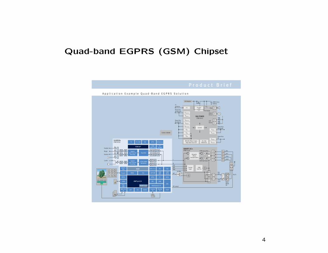
Quad-band EGPRS (GSM) Chipset
P r o d u c t B r i e f
A p p l i c a t i o n E x a m p l e Q u a d - B a n d E G P R S S o l u t i o n
Power BusPeripherals
I2CInterface
Power BusBaseband
I2C
AC-Adaptor
Charger
Pre-Charge
VBB2
VRTC
VBB1
VMemory
VBB USB
VBB Analog
VBB I/O Hi
VUSB Host
SM-POWER(PMB 6811)
Control
BB (LR)/Mem/CoproStep down 600 mA
On-chipReference
VBT BB
VRF3 (BT)
VRF Main
VRF VCXO
AmpVDD
LEDDriver
MotorDriver
M
NiMH/LiIonBattery
Power BusBluetooth
Power BusRF
S-GOLD2(PMB 8876)
DA
A
AD
D
I2S / DAII2S SSC
TEAKLite®
GPTU IR-Memory
GSMCipher Unit
RFControl
Speechand Channel
DecodingEqualizer
DA
AD
Speechand Channel
Encoding
8 PSK/GMSKModulator
DA
AD
SRAM
MOVE Copro
DMAC ICUKeypad
USB FSOTG
FastIrDA
MMC/SDIF
CAPCOM
GPTU
RTC
I2C
JTAG
AUXADC
SCCU
FCDP
EBU
GSMTimer
GEA-1/2/3 CGUAFC
GPIOs
ARM®926 EJ-SUSIM
USARTsSSCUSIFCamera
IFDisplay
IF
Multimedia IC IF
FLASH/SDRAM
SMARTi DC+(PMB 6258) GSM 900/1800
GSM 850/1900
AtomaticOffset
Compensation
ControlLogic
SAMFast PLL
850
900
1800
1900
Rx/Tx
Multi ModePA
850900
18001900
I
Q
CLK
DAT
ENA
AFC
RF Control
26 MHz
Car Kit
Earpiece
Ringer
Headset
MU
X
0* #
321
8
54
7
SDC
MMC
6
9
4

TOPICAL OUTLINE
1. INTRODUCTION TO CELLULAR RADIO SYSTEMS
2. MULTIPATH-FADING CHANNEL MODELLING AND SIMULATION
3. SHADOWING AND PATH LOSS
4. CO-CHANNEL INTERFERENCE AND OUTAGE
5. SINGLE- AND MULTI-CARRIER MODULATION TECHNIQUESAND THEIR POWER SPECTRUM
6. DIGITAL SIGNALING ON FLAT FADING CHANNELS
7. MULTI-ANTENNA TECHNIQUES
8. ADVANCED TOPICS
• MULTI-CARRIER TECHNIQUES
• SPREAD SPECTRUM TECHNIQUES
5

ECE6604
PERSONAL & MOBILE COMMUNICATIONS
Week 1
Introduction,
Path Loss, Co-channel Interference
6

1G Cellular Technologies
• 1979 — Nippon Telephone and Telegraph (NTT) introduces thefirst cellular system in Japan.
• 1981 — Nordic Mobile Telephone (NMT) 900 system introduced byEricsson Radio Systems AB and deployed in Scandinavia.
• 1984 — Advanced Mobile Telephone Service (AMPS) introducedby AT&T in North America.
Feature NTT NMT AMPSFrequency Band 925-940/870-885 890-915 824-849RL/FLa 915-918.5/860-863.5 917-950 869-894(MHz) 922-925/867-870
Carrier Spacing 25/6.25 12.5b 30(kHz) 6.25
6.25Number of 600/2400 1999 832Channels 560
280Modulation analog FM analog FM analog FMaRL = reverse link, FL = forward linkb frequency interleaving using overlapping channels, where the channelspacing is half the nominal channel bandwidth.
7

2G Cellular Technologies
• 1990 — Interim Standard IS-54 (USDC) adopted by TIA.
• 1991 — Japanese Ministry of Posts and Telecommunications stan-dardized Personal Digital Cellular (PDC)
• 1992 — Phase I GSM system is operational (September 1).
• 1993 — Interim Standard IS-95A (CDMA) adopted by TIA.
• 1994 — Interim Standard IS-136 adopted by TIA.
• 1998 — IS-95B standard is approved.
• 2013 — GSM is available in 219 countries, 6.5 billion subscribers.Roaming everywhere except Korea and Japan. IS-95A/B is deployedin 121 countries, IS-54/136 is extinct, PDC only ever existed inJapan is likely extinct.
8

2G Cellular Technologies
Feature GSM/DCS1800/PCS1900 IS-54/136Frequency Band GSM: 890-915/ 824-829/RL/FLa 935-960 869/894(MHz) DCS1800: 1710-1785/ 1930-1990/
1805-1880 1850-1910PCS1900: 1930-1990/1850-1910
Multiple Access F/TDMA F/TDMACarrier Spacing (kHz) 200 30Modulation GMSK π/4-DQPSKBaud Rate (kb/s) 270.833 48.6Frame Size (ms) 4.615 40Slots/Frame 8/16 3/6Voice Coding (kb/s) VSELP(HR 6.5) VSELP (FR 7.95)
RPE-LTP (FR 13) ACELP (EFR 7.4)ACELP (EFR 12.2) ACELP (12.2)
Channel Coding Rate-1/2 CC rate-1/2 CCFrequency Hopping yes noHandoff hard hard
9

2G Cellular Technologies
Feature PDC IS-95Frequency Band 810-826/ 824-829/RL/FLa 940-956 869-894(MHz) 1429-1453/ 1930-1990/
1477-1501 1850-1910Multiple Access F/TDMA F/CDMACarrier Spacing (kHz) 25 1250Modulation π/4-DQPSK QPSKBaud Rate (kb/s) 42 1228.8 Mchips/sFrame Size (ms) 20 20Slots/Frame 3/6 1Voice Coding (kb/s) PSI-CELP (HR 3.45) QCELP (8,4,2,1)
VSELP (FR 6.7) RCELP (EVRC)Channel Coding rate-1/2 BCH FL: rate-1/2 CC
RL: rate-1/3 CCFrequency Hopping no N/AHandoff hard soft
10

3G Cellular Technologies
• 1998 — A group called 3GPP (Third Generation Partnership Project)is created to] produce a common 3G standard based on WCDMA.
• 1999 — The group 3GPP2 is created to harmonize the use of multi-carrier cdma2000
• 2000 — South-Korean Telecom (SKT) launches cdma2000-1X net-work (DL/UL: 153 kbps)
• 2001 — NTT DoCoMo deploys commercial UMTS network in Japan
• 2002 — cdma2000 1xEV-DO (UL: 153 kbps, DL: 2.4 Mb/s)
• 2003 — WCDMA (UL/DL: 384 kbps)
• 2006 — HSPA (UL: 384 kbps, DL: 7.2 Mbps)
• 2007 — cdma2000 1xEV-DO Rev A (UL: 1.8 Mbps, DL: 3.1 Mbps)
• 2010 — HSPA (UL: 5.8 Mbps, DL: 14.0 Mbps), cdma2000 1xEV-DO Rev A (UL: 1.8 Mbps, DL: 3.1 Mbps)
• 2014 — 555 HSPA networks in 203 countries, 365 commercialHSPA+ networks in 157 countries (most UL: 22 Mbps, DL: 168Mbps) — 175 commercial 1xEV-DO Rev A networks
11

3G Cellular Technologies
Feature W-CDMA cdma2000Multiple Access DS-CDMA DS-CDMAChip Rate (Mcps) 3.84 1.2288Carrier Spacing (MHz) 5 1.25Frame Length (ms) 10 5/20Modulation FL: QPSK FL: BPSK/QPSK
RL: BPSK RL: BPSK64-ary orthogonal
Coding rate-1/2, 1/3 rate-1/2, 1/3, 1/4,K = 9 conv. code 1/6 K = 9 conv. coderate-1/3 rate-1/2, 1/3, 1/4,K = 4 turbo code 1/5, K = 4 turbo code
Interleaving inter/intraframe intraframeSpreading FL: BPSK complex
RL: QPSKInter BS asynchronous synchronoussynchronization
12

4G Cellular Technologies
• LTE and WiMAX are sometimes branded as 4G cellular technologies.
• LTE: Currently seeing rapid deployment
– There are 318 LTE networks in 111 countries.
– 170 million subscribers worldwide.
• LTE-A: seeing initial deployment.
– There are 17 LTE-A networks in 12 countries.
• WiMAX: Currently seeing less rapid deployment:
– There are 580 commercial WiMax networks in 149 countries.
– 33.4 million subscribers worldwide.
13
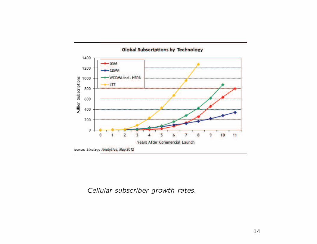
Cellular subscriber growth rates.
14

WIRELESS LANs (WiFi)
• IEEE 802.11 – Direct Sequence Spread Spectrum (1-and-2 Mb/s,2.4GHz)
• IEEE 802.11b – Complimentary Code Keying (CCK) (5.5-and-11Mb/s, 2.4GHz)
• IEEE 802.11g/a – Orthogonal Frequency Division Multiplexing (OFDM)(6-to-54 Mb/s, 2.4/5GHz)
• IEEE 802.11e – MAC enhancements for Quality of Service (QoS)
• IEEE 802.11i – Security
• IEEE 802.11n – MIMO physical layer
• Femtocells: integrate WiFi with cellular.
– Benefits: Frees up cellular capacity and reduces BS power con-sumption.
– Drawbacks: MS power drain due to femtocell searching. Fastfemtocell-to-cellular handoff is needed to prevent dropped calls.
15

WIRELESS PANs
• IEEE Std 802.15.1-2002 - 1Mb/s WPAN/Bluetooth v1.x derivativework - uses frequency hop spread spectrum.
– Today Bluetooth is managed by the Bluetooth Special InterestGroup.
• P802.15.2- Recommended Practice for Coexistence in UnlicensedBands
• P802.15.3 - 20+ Mb/s High Rate WPAN for Multimedia and DigitalImaging
• P802.15.3a - 110+ Mb/s Higher Rate Alternative PHY for 802.15.3- Ultra wideband (UWB)
• P802.15.4 - 200 kb/s max for interactive toys, sensor and automa-tion needs
• Applications include (mobile) ad hoc networks, sensor networks
16

FREQUENCY RE-USE AND THE CELLULAR
CONCEPT
CD
B
A
4-Cell
C
AB
3-Cell 7-Cell
A
C
F
D
GE
B
Commonly used hexagonal cellular reuse clusters.
• Tessellating hexagonal cluster sizes, N, satisfy
N = i2 + ij + j2
where i, j are non-negative integers and i ≥ j.
– hence N = 1, 3, 4, 7, 9, 12, . . . are allowable.
17

B
G
F
G
D
B
C
G
A
F
B
G
D
E
C
A
E
C
A
F
B
A
F
G
D
D
E
C
A
F
G
B
Cellular layout using 7-cell reuse clusters.
• Real cells are not hexagonal, but irregular and overlapping.
• Frequency reuse introduces co-channel interference and adjacentchannel interference.
18

CO-CHANNEL REUSE FACTOR
A
AD
R
Frequency reuse distance for 7-cell reuse clusters.
• For hexagonal cells, the co-channel reuse factor is
D
R=
√3N
19

RADIO PROPAGATION MECHANISMS
• Radio propagation is by three mechanisms:
– Reflections off of objects larger than a wavelength, sometimescalled scatterers.
– Diffractions around the edges of objects
– Scattering by objects smaller than a wavelength
• A mobile radio environment is characterized by three nearly inde-pendent propagation factors:
– Path loss attenuation with distance.
– Shadowing caused by large obstructions such as buildings, hillsand valleys.
– Multipath-fading caused by the combination of multipath propa-gation and transmitter, receiver and/or scatterer movement.
20
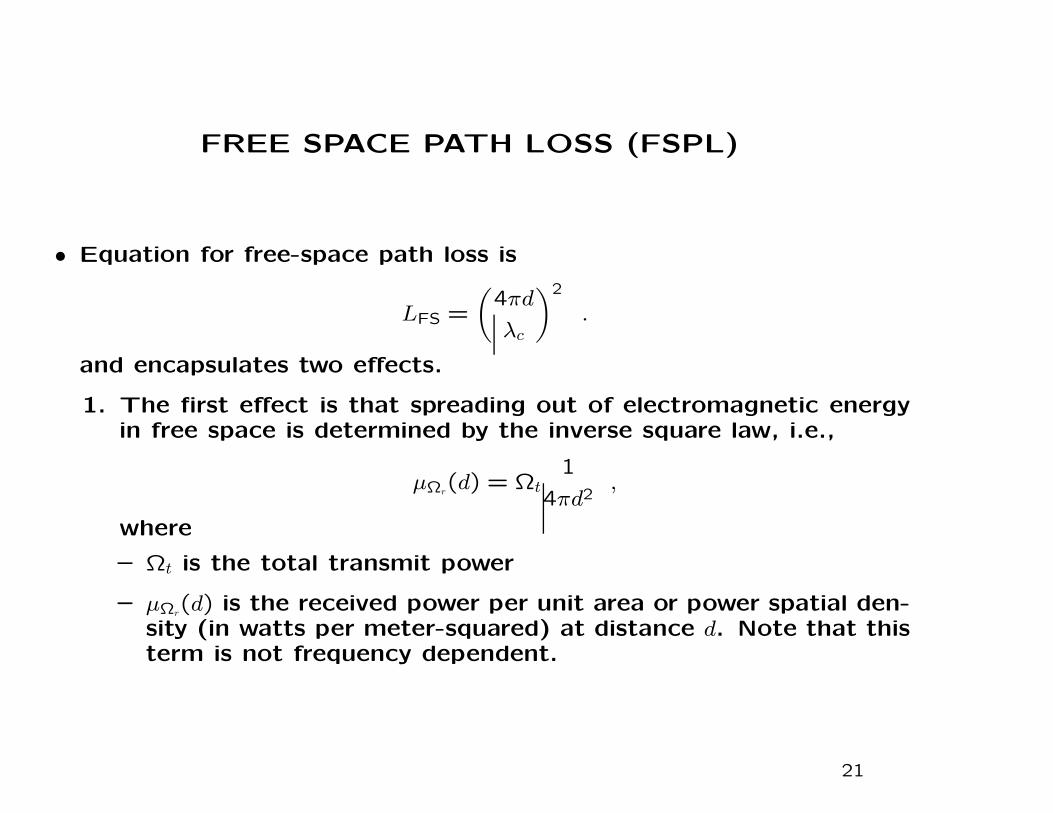
FREE SPACE PATH LOSS (FSPL)
• Equation for free-space path loss is
LFS =
(
4πd
λc
)2
.
and encapsulates two effects.
1. The first effect is that spreading out of electromagnetic energyin free space is determined by the inverse square law, i.e.,
µΩr(d) = Ωt
1
4πd2,
where
– Ωt is the total transmit power
– µΩr(d) is the received power per unit area or power spatial den-
sity (in watts per meter-squared) at distance d. Note that thisterm is not frequency dependent.
21

FREE SPACE PATH LOSS (FSPL)
• Second effect
2. The second effect is due to aperture, which determines how wellan antenna picks up power from an incoming electromagneticwave. For an isotropic antenna, we have
µΩp(d) = µΩr
(d)λ2c
4π= Ωt
(
λc
4πd
)2
,
where µΩp(d) is the received power. Note that aperature is en-
tirely dependent on wavelength, λc, which is how the frequency-dependent behavior arises in the free space path loss.
• For free space, the propagation path loss is
LFS (dB) = 10log10
Ωt
µΩp(d)
= 10log10
(
4πd
λc
)2
= 10log10
(
4πd
c/fc
)2
= 20log10fc + 20log10d− 147.55 dB .
22

PROPAGATION OVER A FLAT SPECULAR SURFACE
d1
d2
BS
MS
d
hb
hm
1

• The length of the direct path is
d1 =
√
d2 + (hb − hm)2
and the length of the reflected path is
d2 =
√
d2 + (hb + hm)2
d = distance between mobile and base stations
hb = base station antenna height
hm = mobile station antenna height
• Given that d ≫ hbhm, we have d1 ≈ d and d2 ≈ d.
• However, since the wavelength is small, the direct and reflectedpaths may add constructively or destructively over small distances.The carrier phase difference between the direct and reflected pathsis
φ2 − φ1 =2π
λc(d2 − d1)
2
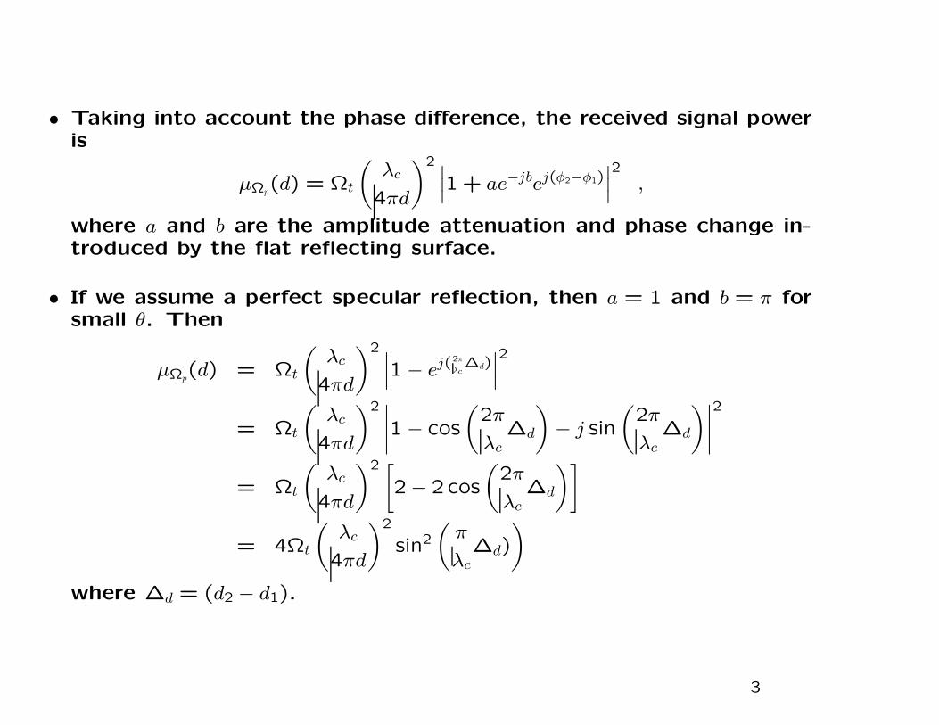
• Taking into account the phase difference, the received signal poweris
µΩp(d) = Ωt
(
λc
4πd
)2 ∣∣
∣1+ ae−jbej(φ2−φ1)
∣
∣
∣
2
,
where a and b are the amplitude attenuation and phase change in-troduced by the flat reflecting surface.
• If we assume a perfect specular reflection, then a = 1 and b = π forsmall θ. Then
µΩp(d) = Ωt
(
λc
4πd
)2 ∣∣
∣1− ej(
2π
λc∆d)
∣
∣
∣
2
= Ωt
(
λc
4πd
)2 ∣∣
∣
∣
1− cos
(
2π
λc∆d
)
− j sin
(
2π
λc∆d
)∣
∣
∣
∣
2
= Ωt
(
λc
4πd
)2 [
2− 2 cos
(
2π
λc∆d
)]
= 4Ωt
(
λc
4πd
)2
sin2
(
π
λc∆d)
)
where ∆d = (d2 − d1).
3
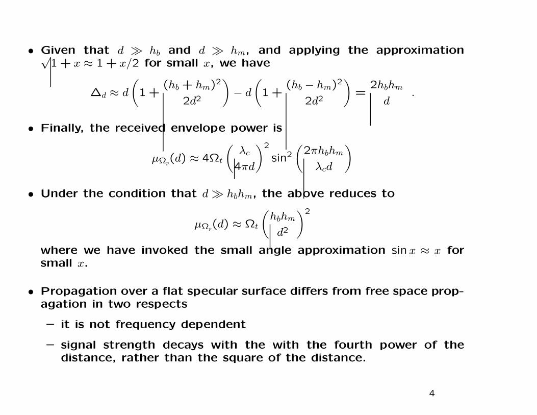
• Given that d ≫ hb and d ≫ hm, and applying the approximation√1+ x ≈ 1+ x/2 for small x, we have
∆d ≈ d
(
1+(hb + hm)2
2d2
)
− d
(
1+(hb − hm)2
2d2
)
=2hbhm
d.
• Finally, the received envelope power is
µΩp(d) ≈ 4Ωt
(
λc
4πd
)2
sin2
(
2πhbhm
λcd
)
• Under the condition that d ≫ hbhm, the above reduces to
µΩp(d) ≈ Ωt
(
hbhm
d2
)2
where we have invoked the small angle approximation sin x ≈ x forsmall x.
• Propagation over a flat specular surface differs from free space prop-agation in two respects
– it is not frequency dependent
– signal strength decays with the with the fourth power of thedistance, rather than the square of the distance.
4

10 100 1000 10000Path Length, d (m)
10
100
1000
Path
Los
s (d
B)
Propagation path loss Lp (dB) with distance over a flat reflecting surface;hb = 7.5 m, hm = 1.5 m, fc = 1800 MHz.
LFE (dB) =
[
(
λc
4πd
)2
4 sin2
(
2πhbhm
λcd
)
]−1
5

• In reality, the earth’s surface is curved and rough, and the signalstrength typically decays with the inverse β power of the distance,and the received power at distance d is
µΩp(d) =
µΩp(do)
(d/do)β
where µΩp(do) is the received power at a reference distance do.
• Expressed in units of dBm, the received power is
µΩp (dBm)(d) = µΩp (dBm)
(do)− 10β log10(d/do) (dBm)
• β is called the path loss exponent. Typical values of µΩp (dBm)(do) and
β have been determined by empirical measurements for a variety ofareas
Terrain µΩp (dBm)(do = 1.6 km) β
Free Space -45 2Open Area -49 4.35North American Suburban -61.7 3.84North American Urban (Philadelphia) -70 3.68North American Urban (Newark) -64 4.31Japanese Urban (Tokyo) -84 3.05
6

Co-channel Interference
Worst case co-channel interference on the forward channel.
7

Worst Case Co-Channel Interference
• For N = 7, there are six first-tier co-channel BSs, located at dis-tances
√13R,4R,
√19R,5R,
√28R,
√31R from the MS.
• Assuming that the BS antennas are all the same height and all BSstransmit with the same power, the worst case carrier-to-interferenceratio, Λ, is
Λ =R−β
(√13R)−β + (4R)−β + (
√19R)−β + (5R)−β + (
√28R)−β + (
√31R)−β
=1
(√13)−β + (4)−β + (
√19)−β + (5)−β + (
√28)−β + (
√31)−β
.
• With a path loss exponent β = 3.5, the worst case Λ is
Λ(dB) =
14.56 dB for N = 79.98 dB for N = 47.33 dB for N = 3
.
– Shadows will introduce variations in the worst case Λ.
8

Cell Sectoring
Worst case co-channel interference on the forward channel with 120o cellsectoring.
9

• 120o cell sectoring reduces the number of co-channel base stationsfrom six to two. For N = 7, the two first tier interferers are locatedat distances
√19R,
√28R from the MS.
• The carrier-to-interference ratio becomes
Λ =R−β
(√19R)−β + (
√28R)−β
=1
(√19)−β + (
√28)−β
.
• Hence
Λ(dB) =
20.60 dB for N = 717.69 dB for N = 413.52 dB for N = 3
.
• For N = 7, 120o cell sectoring yields a 6.04 dB C/I improvementover omni-cells.
• The minimum allowable cluster size is determined by the thresholdΛ, Λth, of the radio receiver. For example, if the radio receiver hasΛth = 15.0 dB, then a 4/12 reuse cluster can be used (4/12 means4 cells or 12 sectors per cluster).
10