ece103. fall 2013 experiment #3 student name(s) and … 3 fa2013.pdftake the following precautions:...
TRANSCRIPT

ECE103. Fall 2013 Experiment #3 Student name(s) and lab section:
Page 1 from 6
Experiment #3 Introduction to Laboratory Equipment
Objective: In this lab you will be introduced to basic laboratory equipment that you will use in the rest of the course. You will also explore the behavior of simple DC circuits. * Methodology: This lab involves measuring voltage and current and performing calculations. You are expected to show your results and work in this packet or also attach additional pages. * General Procedures: Please read before you start working • You must take good care of the equipment and follow basic safety rules in order to
maintain the equipment in good working conditions, and to prevent accidents. • Always check connections before applying power to any circuit or device. You do
not want to exceed the power limitations of the device or otherwise it will be damaged.
• When using the multimeter and you are not sure of the approximate values you will be measuring start by selecting the least sensitive scale setting then slowly work your way down.
• Disconnect power supplies (current and voltage sources) from a circuit before measuring resistance as multimeters use internal power sources when measuring resistances.
• Switch the power supply off when making adjustments in your circuit connections or when adding new components to avoid short circuit.
* Equipment list: You will use the acquisition portable device Xplorer GLX® from Pasco. This is a handset with multiple functions capable to acquire digital signals from a variety of detectors available in the laboratory. Read carefully the quick guide to be familiar with the multiple functions of the device. Be aware of the voltage/current limits of the device you are using consulting the User’s Guide. Voltage probes are designed to measure voltages between +10V and -10V. If you are not sure about the characteristics of the equipment a complete user guide can be found in: http://pasco.com/file_downloads/product_manuals/Xplorer-GLX-Manual-PS-2002.pdf Take the following precautions:
ü DO NOT EXCEED THE MAXIMUM VOLTAGE OR YOU CAN DAMAGE PERMANENTLY THE Xplorer.
ü Resistors can get very hot when connected in a circuit. Do not touch the resistors
when the circuit is closed • Basic Circuit Elements:

ECE103. Fall 2013 Experiment #3 Student name(s) and lab section:
Page 2 from 6
The figure below shows the symbols of the simplest circuit elements that you will use in the different laboratories during the semester
• Resistor Color Bands: Carbon resistors are the most common ones, and come in a wide range of power ratings. Their resistances are identified by a color code. In addition to the resistance value, a tolerance value is included in the code. Typically carbon resistors employ 5% tolerances, and can handle ¼ W. This means that the current and voltage have to be controlled not to exceed the power ratings. On each resistor you will find 3 or 4 color bands , each color represents number, the colors which you are going to see are :-
Color Represents Black 0
ECE103. Fall 2013 Experiment #3 Student name(s) and lab section:
Page 3 from 6
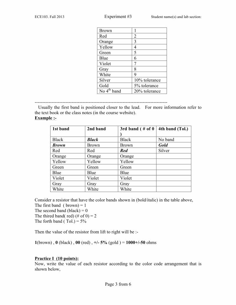
Brown 1 Red 2 Orange 3 Yellow 4 Green 5 Blue 6 Violet 7 Gray 8 White 9 Silver 10% tolerance Gold 5% tolerance No 4th band 20% tolerance
-------------------------------------------------------------------------------------- Usually the first band is positioned closer to the lead. For more information refer to the text book or the class notes (in the course website). Example :-
1st band 2nd band 3rd band ( # of 0 )
4th band (Tol.)
Black Black Black No band Brown Brown Brown Gold Red Red Red Silver Orange Orange Orange Yellow Yellow Yellow Green Green Green Blue Blue Blue Violet Violet Violet Gray Gray Gray White White White
Consider a resistor that have the color bands shown in (bold/italic) in the table above, The first band ( brown) = 1 The second band (black) = 0 The thired band( red) (# of 0) = 2 The forth band ( Tol.) = 5% Then the value of the resistor from lift to right will be :- 1(brown) , 0 (black) , 00 (red) , +/- 5% (gold ) = 1000+/-50 ohms Practice I (10 points): Now, write the value of each resistor according to the color code arrangement that is shown below,
ECE103. Fall 2013 Experiment #3 Student name(s) and lab section:
Page 4 from 6
1st band 2nd band 3rd band 4th band Resistance +/- Tolerance Orange Orange Red Silver Green Blue Red No band Brown Black Orange Gold Black Brown Brown No band • Voltage/current sensors and Power Supplies: 1.) Obtain a set of 3 resistors with values between R=10Ω and R=60Ω
ü Using the color code find the nominal value of the three resistors ü Now check the value of your resistor using the ohmmeter by connecting the 2
terminals of the resistor to the 2 leads of the ohmmeter. Make sure the resistance function is selected on the meter.
Complete the following table
Resistor #1 #2 #3 Nominal value Measured value - How much of a difference is there between the ideal and true resistance values? Does this fit in the acceptable tolerance limits? ...........................................................................................................................................................................................................................................
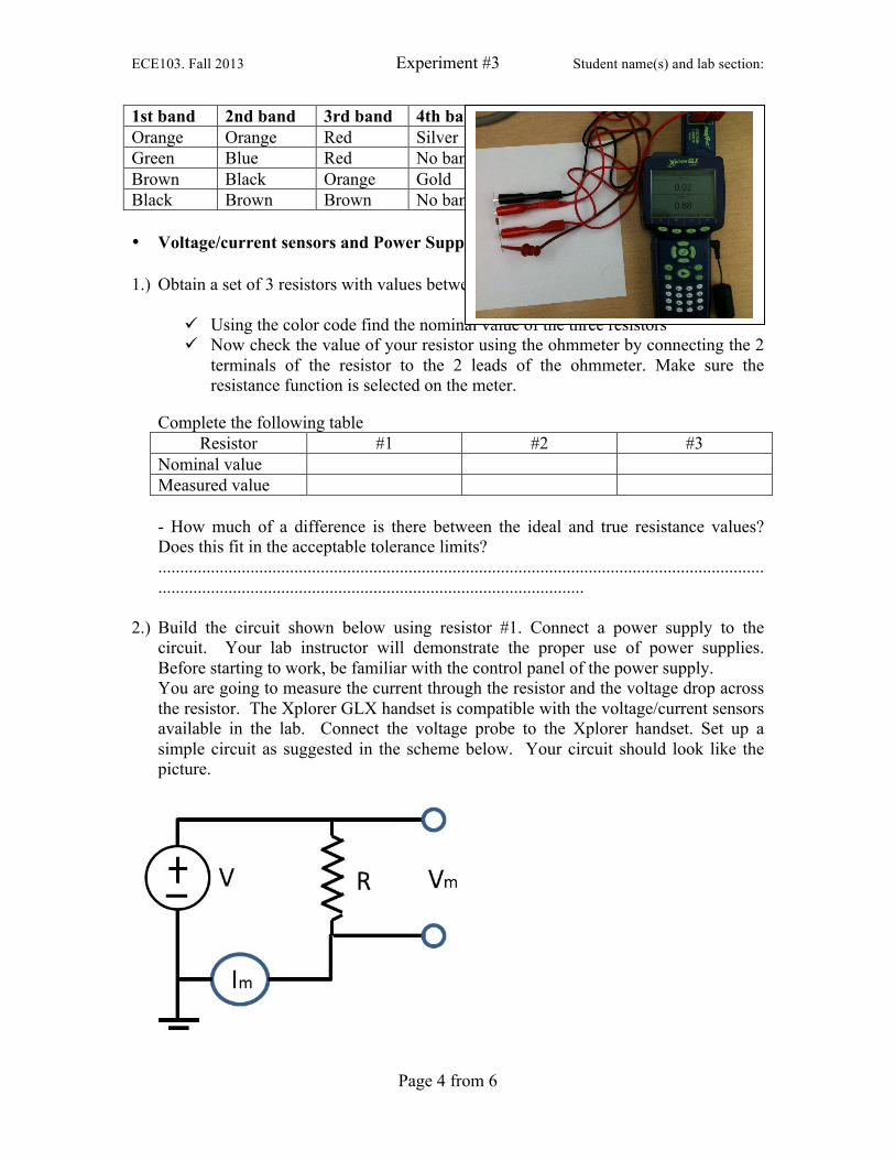
2.) Build the circuit shown below using resistor #1. Connect a power supply to the
circuit. Your lab instructor will demonstrate the proper use of power supplies. Before starting to work, be familiar with the control panel of the power supply. You are going to measure the current through the resistor and the voltage drop across the resistor. The Xplorer GLX handset is compatible with the voltage/current sensors available in the lab. Connect the voltage probe to the Xplorer handset. Set up a simple circuit as suggested in the scheme below. Your circuit should look like the picture.

ECE103. Fall 2013 Experiment #3 Student name(s) and lab section:
Page 5 from 6
ü Connect the voltage (Vm) and current (Im) sensors to the circuit. How should they
be connected?. Remember to refer the negative terminal of the source to ground. Consult with the TA if you have doubts.
ü Complete the connections with the voltage source OFF. After checking the connections, make sure that the settings in the voltage source are below the maximum allowed limit (10 V). Your circuit should look like the picture above.
ü Utilize the +/- 6 V output of the voltage source ü Remember, you should always turn off the power to a circuit while modifying it.
Afterwards, you will need to turn the power back on to make the measurement. The best way to turn the power on and off to the circuit is to use the “Output On/Off” button on the power supply. This allows the voltage and current settings to remain unchanged.
Practice II (20 points) - Using your circuit solving knowledge, what value of Vm do you expect across the resistor?
a- Set the voltage in this source to 1 V, measure the voltage indicated by the voltage sensor and the current.
b- Increase the voltage in the source is steps of 1V up to a maximum voltage of 6 V c- Change to resistor #2 and repeat the measurements indicated in a) and b). d- Complete the following table
R#1 R#2 R#3 Vm [V] Im [A] Vm [V] Im [A] Vm [V] Im [A]
Practice III (10 points) Plot the data for the three resistors in the same graph using MATLAB. From the graph determine the best fit and the value of the resistance in each case. How this value compares with the nominal value?
Resistor #1 Resistor #2 Resistor #3 Measured from the graph Nominal Practice IV (10 pints)

ECE103. Fall 2013 Experiment #3 Student name(s) and lab section:
Page 6 from 6
Now that you know V and I in the circuit, find R using Ohm’s law: V= IR. How does this resistance value compare with the color band method and the value you measured using the ohmmeter? Color band method Ideal value
Ohmmeter method Measured value
Ohm’s law: V= IR Calculated value
- Comment on your results:- ....................................................................................................................................................................................................................................................................................................................................................................................