ece type-approval...
TRANSCRIPT
49.49.946.01.01
CT-11-03 Rev 4 Page 1 of 3 NSAI, 1 Swift Square, Northwood, Santry, Dublin 9, Ireland. Telephone: (+353+1) 807 3800, Facsimile: 01-807 3844
ECE TYPE-APPROVAL CERTIFICATE
Communication Concerning: Approval granted
Approval extended
Approval refused
Approval withdrawn
Production definitively discontinued
Of a type of electrical/electronic sub-assembly with regard to Regulation No.10.
.
Approval No: E24 10R-052162 Extension No: N/A
Reason for extension: N/A.
1. Make (trade name of manufacturer): SEF Industrie
2. Type and general commercial description: SBS DPA 130 TC 01
Variant(s): SBS DPA 130 SC 01
SBS DPA 130 SB 00
SBS DPA 080 SC 01
SBS DPA 080 TC 01
SBS DPA 070 TC 01
SBS DPA 070 SC 01
SBS DPA 070 SB 00
3. Means of identification of type, if marked on the component: SBS DPA 130 TC 01
S/N: 2416
3.1 Location of that marking: On the unit to be molded
4. Category of vehicle: See Appendix
5. Name and address of manufacturer: SEF Industrie
9 rue Gustave Eiffel
77610 Fontenay-Tresigny
France
6. In the case of components and separate technical units,
location and method of affixing of the ECE approval mark: On the bottom of the case to be molded
7. Address(es) of assembly plant(s): See point 0.8 of the information document
for details.
49.49.946.01.01
CT-11-03 Rev 4 Page 2 of 3 NSAI, 1 Swift Square, Northwood, Santry, Dublin 9, Ireland. Telephone: (+353+1) 807 3800, Facsimile: 01-807 3844
Approval No: E24 10R-052162 Extension No: N/A
8. Additional information (where applicable): See appendix
9. Technical service responsible for carrying out the tests: TÜV SÜD Auto Service GmbH
Westendstraße 199
D-80686 München
10. Date of test report: 20.02.2017
11. Number of test report: 17-00017-CP-PRG-00
12. Remarks (if any): See Appendix
13. Place: Dublin
14. Date: 28th
February, 2017.
15. Signature:
16. The index to the information package lodged with the approval authority, which may be obtained on
request is attached.
49.49.946.01.01
CT-11-03 Rev 4 Page 3 of 3 NSAI, 1 Swift Square, Northwood, Santry, Dublin 9, Ireland. Telephone: (+353+1) 807 3800, Facsimile: 01-807 3844
Approval No: E24 10R-052162 Extension No: N/A
Appendix
To type-approval communication concerning the type approval
of an electrical/electronic sub-assembly under Regulation No.10.
1. Additional information
1.1. Electrical system rated voltage: 12V DC, negative ground
1.2. This ESA can be used on any vehicle type with the
following restrictions: See manufacturer’s specifications.
1.2.1 Installation conditions, if any: See manufacturer’s specifications.
1.3. This ESA can only be used on the following vehicle types: N/A
1.3.1 Installation conditions, if any: N/A
1.4. The specific test method(s) used and the frequency ranges
covered to determine immunity were: Bulk current injection method
Frequency range: 20 -200 MHz
Free field substitution menthod
Frequency range: 200 - 2000 MHz
1.5. Laboratory accredited to ISO 17025 and recognized by the Approval
Authority responsible for carrying out the tests: TÜV SÜD Auto Service GmbH
2. Remarks: N/A
Appendix to type-approval communication concerning the
type approval of a vehicle under Regulation No.10.
1. Additional information
2. Special devices for the purpose of Annex 4 to this Regulation: N/A
3. Electrical system rated voltage: N/A
4. Type of bodywork: N/A
5. List of electronic systems installed in the tested vehicle(s)
not limited to the items in the information document: N/A
5.1 Vehicle equipped with 24 GHz short-range radar equipment (yes/no): N/A
6. Laboratory accredited to ISO 17025 and recognized by the Approval
Authority responsible for carrying out the tests: N/A
7. Remarks: N/A
49.49.946.01.01
Page 1 of 2 NSAI, 1 Swift Square, Northwood, Santry, Dublin 9, Ireland. Telephone: (+353+1) 807 3800, Facsimile: 01-807 3844
Approval No: E24 10R-052162 Extension No: N/A
Index to the Information Package Date of issue: 28
th February, 2017.
Date of latest amendment: N/A
Reason for extension/revision: N/A
1. Additional conditions, and advisory
notes on legal alternatives.
2. Test report(s)
- numbers(s): 17-00017-CP-PRG-00
- date of issue: 20.02.2017
- date of latest amendment: N/A
3. Information document
- number(s): 010 – SBS DPA – 00
- date of issue: 18.07.2016
- date of latest amendment: N/A
Documentation: 47 pages
49.49.946.01.01
Page 2 of 2 NSAI, 1 Swift Square, Northwood, Santry, Dublin 9, Ireland. Telephone: (+353+1) 807 3800, Facsimile: 01-807 3844
Approval No: E24 10R-052162 Extension No: N/A
Appendix: Additional conditions, and advisory notes on legal alternatives
A: Additional conditions:
1. The attached technical report, with any of its attachments, forms part of this Type Approval certificate.
2. Each type from series production shall be to the measurements specified in the attached drawings, and shall be
manufactured only from the materials specified in the Approval documents.
3. Changes in the type are permitted only with the explicit permission of NSAI. Breaches of this requirement will
lead to a withdrawal of the Type Approval, and in addition may be subject to criminal prosecution.
4. At regular intervals, any tests or associated checks prescribed by the applicable legislation to verify continued
conformity with the approved type shall be carried out. The manufacturer shall demonstrate compliance with
this by submitting to NSAI evidence of adequate arrangements and documented control plans for each type
approved.
5. Any set of samples or test pieces showing evidence of non-conformity shall give rise to further sampling and
testing and all steps shall be taken to restore conformity of production.
6. This Type Approval will expire when it is surrendered by the holder, or withdrawn by NSAI, or when the
approved type no longer conforms to legal requirements. The recall of the Type Approval can be issued by
NSAI when the conditions required for the issuing or continuation of the Type Approval are no longer current,
or when the Approval holder is in breach of the duties attached to the Type Approval, or when it is established
that the approved type no longer meets the requirements of traffic safety.
7. Changes in the company name, address or manufacturing site, as well as in any of the sales or other agents
specified in the issuing of the approval must immediately be notified to NSAI.
8. The duties imposed by the issuing of this certificate are not transferable. The legal protection of third parties is
not affected by this certificate.
9. When the manufacture or sale of the system, component or separate technical unit has not been started within
one year of the date of issue of this certificate, then NSAI is to be informed. This requirement also applies
when the manufacture or sale has been halted for more than one year, or when it ought to have been halted for
more than one year. The initial commencement of manufacture or sale, or the resumption of
manufacture or sale, shall then be notified to NSAI within one month of commencement or resumption.
B: Legal Options:
Any objection to the requirements set out in this certificate shall be made within one month of the date of issue.
The objection shall be made, in writing, to NSAI in Dublin.
TÜV SÜD Auto Service GmbH
Westendstraße 199 D-80686 München
Test Report No.: Manufacturer: Type:
17-00017-CP-PRG-00 SEF Industrie, France SBS DPA 130 TC 01 Page 1/5
Test report
No.: 17-00017-CP-PRG-00
Test of a type of a electronic sub-assembly (ESA)
with regard to ECE Regulation No. 10.05
Approval subject: Electromagnetic compatibility
Approval status
Granting of a type approval
Extension to type approval no.
E24 10R-052162
TÜV SÜD Auto Service GmbH
Westendstraße 199 D-80686 München
Test Report No.: Manufacturer: Type:
17-00017-CP-PRG-00 SEF Industrie, France SBS DPA 130 TC 01 Page 2/5
I. General
1. Technical description: Smart connecting system for rear lamps
1.1 Trade mark or trade name: SEF Industrie
1.2 Type: SBS DPA 130 TC 01
1.2.1 Variants: SBS DPA 130 SC 01 SBS DPA 130 SB 00 SBS DPA 080 SC 01 SBS DPA 080 TC 01 SBS DPA 070 TC 01 SBS DPA 070 SC 01 SBS DPA 070 SB 00
1.2.2 Commercial name:
N/A
1.3 Characteristics for type identification:
Product and serial numbers
1.4 Position of the marking:
On the unit
1.5 Kind of marking:
To be molded
1.6 Manufacturer’s name and address: SEF Industrie 9 rue Gustave Eiffel 77610 Fontenay-Tresigny France
1.7 Address of assembly plant: ELCOM, s.r.o. Jesenná 2695/26 080 01 Prešov Slovakia
GTP (Groupe Technologique du Perche) 4 Rue des Sablons 28240 Belhomert Farnce
ALTRICS SAS (head company) via Globe Technologies (subdivision of ALTRICS SAS) Km6, Route de Tunis BP18 8020 Soliman Tunisia
1.8 No. of information document:
010 – SBS DPA – 00
E24 10R-052162
TÜV SÜD Auto Service GmbH
Westendstraße 199 D-80686 München
Test Report No.: Manufacturer: Type:
17-00017-CP-PRG-00 SEF Industrie, France SBS DPA 130 TC 01 Page 3/5
II.
Test report
2. Carrying out of the test
The tests were carried out with the following representative ESA.
Model: SBS p/n: DPA 130 TC 01 s/n: 2416
Date and place of testing: 22 - 23 June 2016 EMITECH, Montigny le Bretonneux, France
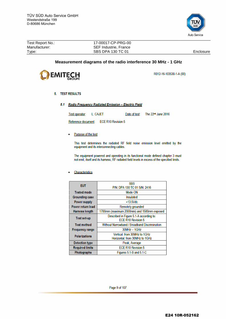
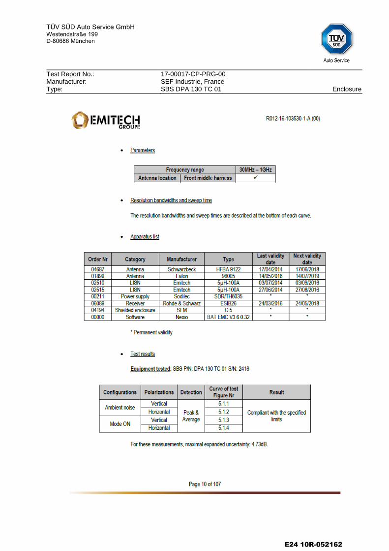
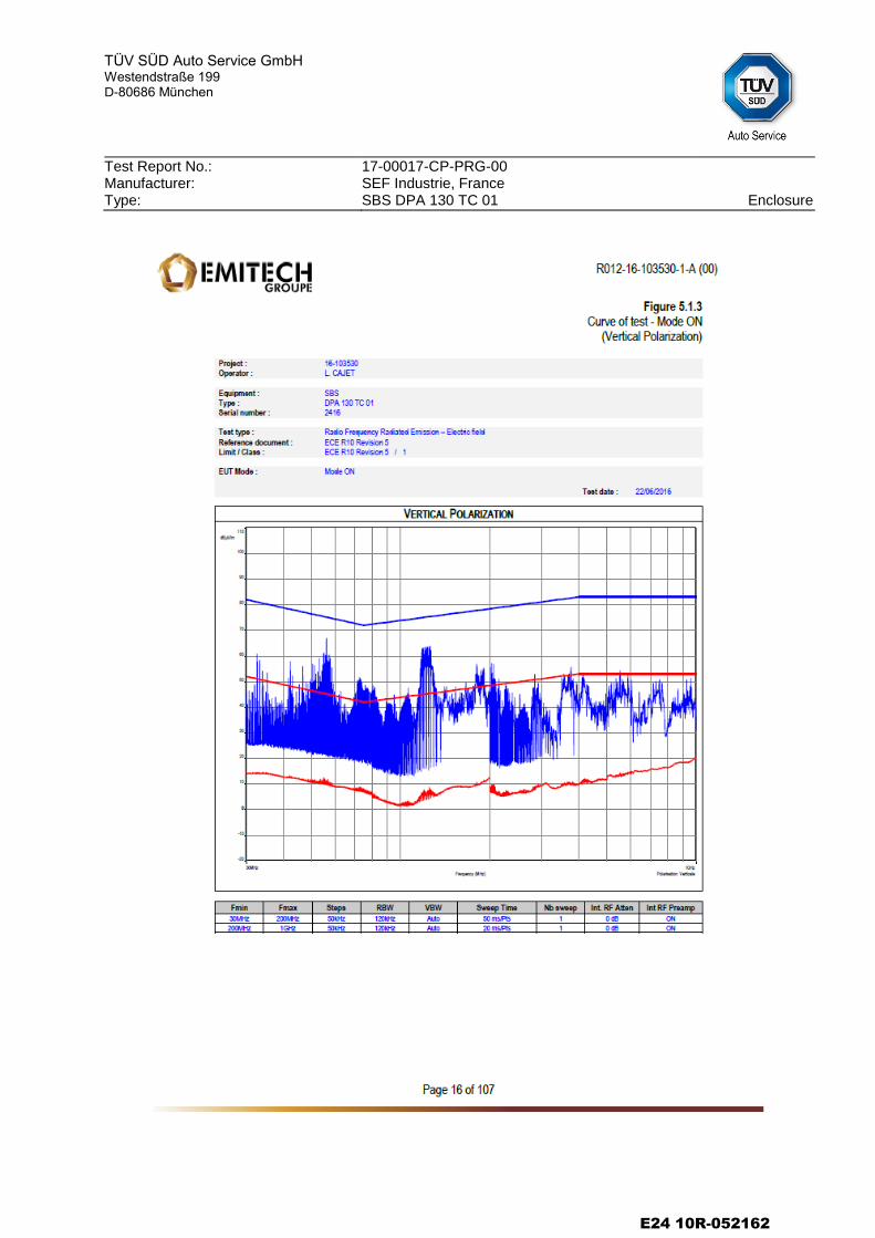
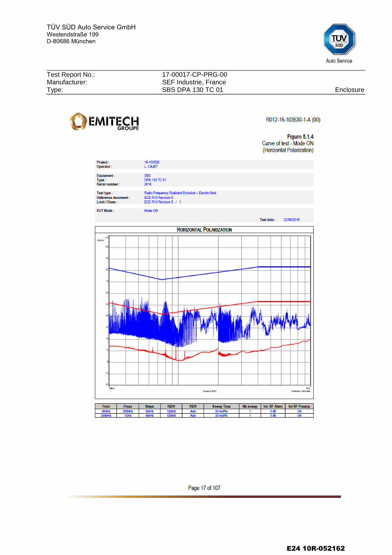
2.1 Broadband electromagnetic interference generated by ESA
2.1.1 Method of measurement: Measured by the method described in annex 7
of ECE-Regulation No. 10.
2.1.2 Results: The measured values, expressed in dB V/m, are below the reference limits. The test was passed.
2.2 Narrowband electromagnetic interference generated by ESA
2.2.1 Method of measurement: Measured by the method described in annex 8
of ECE-Regulation No. 10.
2.2.2 Results: The measured values, expressed in dB V/m, are below the reference limits. The test was passed.
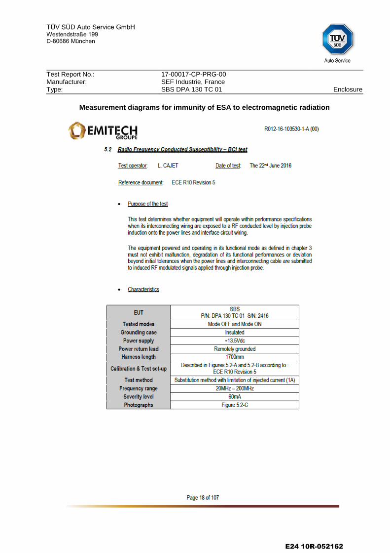
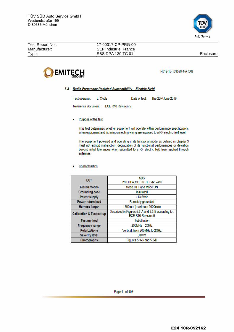
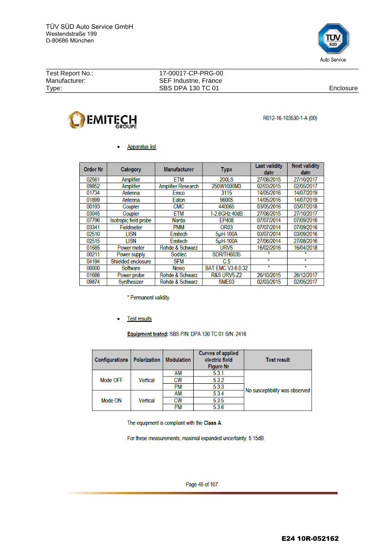
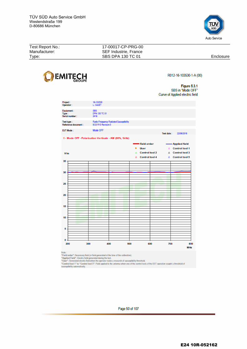
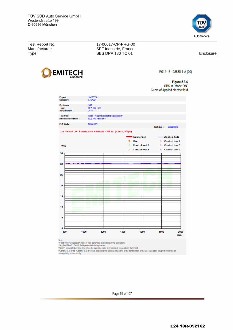
2.3 Immunity of ESA to electromagnetic radiation
2.3.1 Method of measurement: Measured in the anechoic chamber as de-
scribed in annex 9 of ECE-Regulation No. 10.
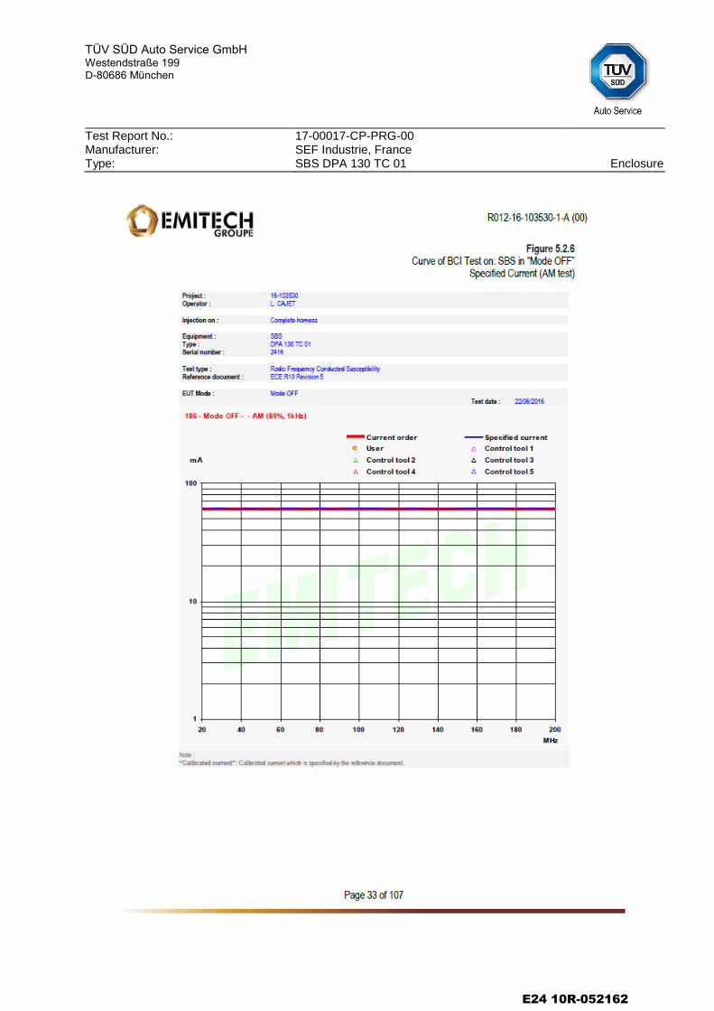
2.3.2 Performance criteria: No degradation of function by testing with 60mA (BCI) and 30 V/m (electric field).
2.3.3 Results: The ESA has not exhibited any unacceptable malfunction. The claimed functional state was fulfilled during the test. The test was passed.
E24 10R-052162
TÜV SÜD Auto Service GmbH
Westendstraße 199 D-80686 München
Test Report No.: Manufacturer: Type:
17-00017-CP-PRG-00 SEF Industrie, France SBS DPA 130 TC 01 Page 4/5
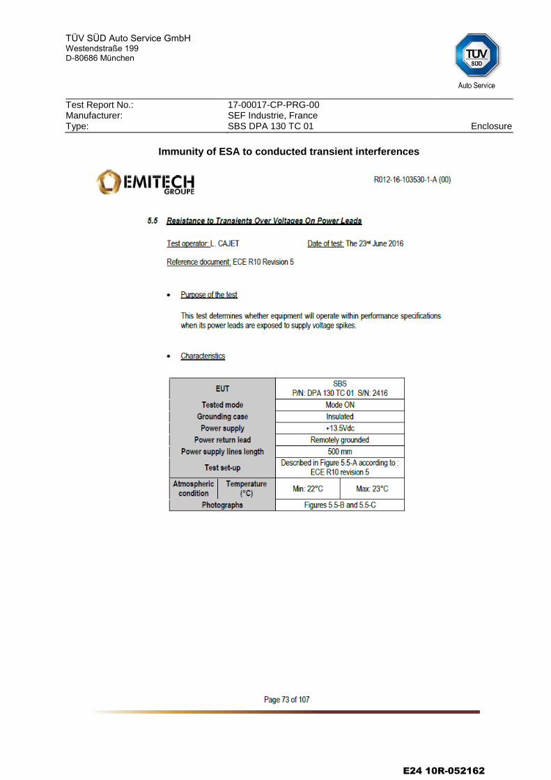
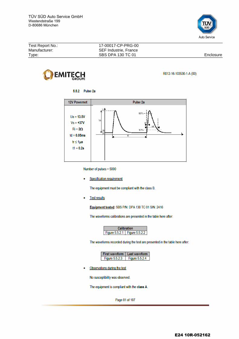
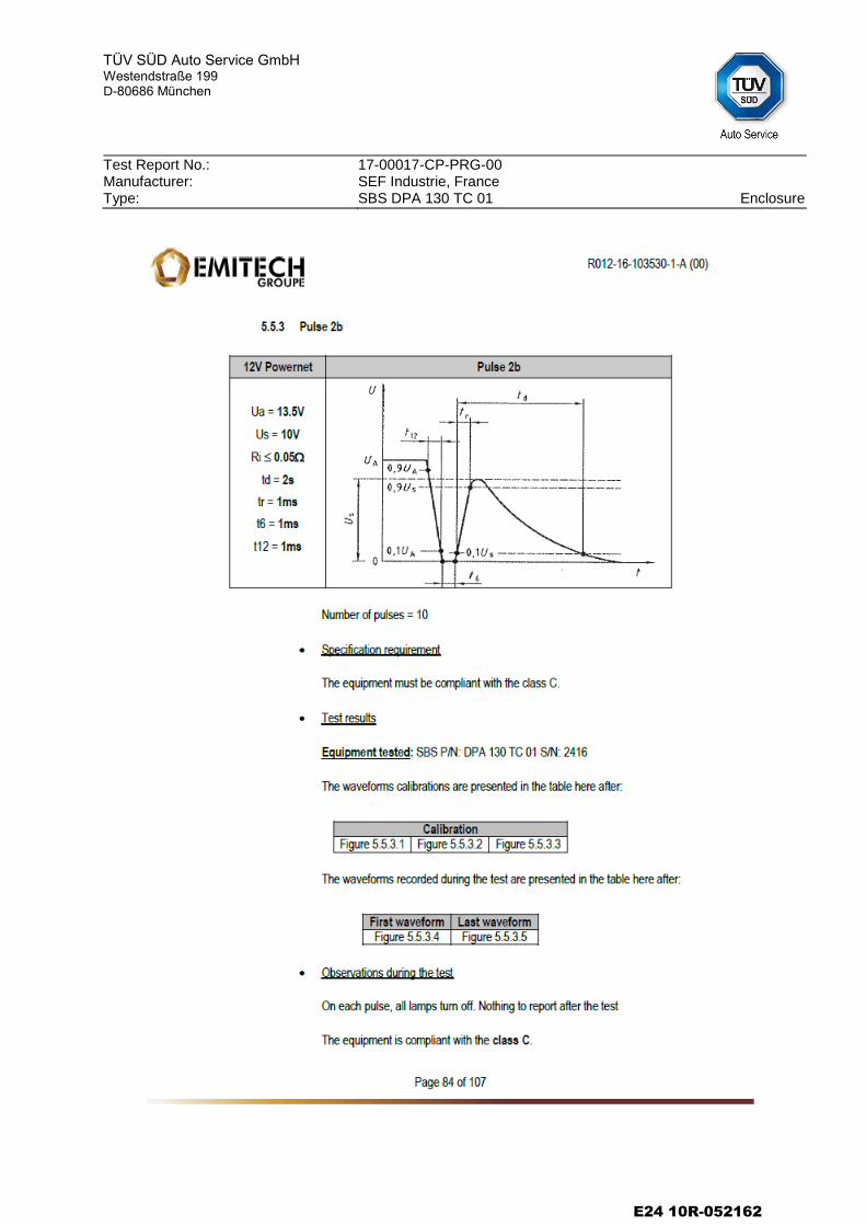
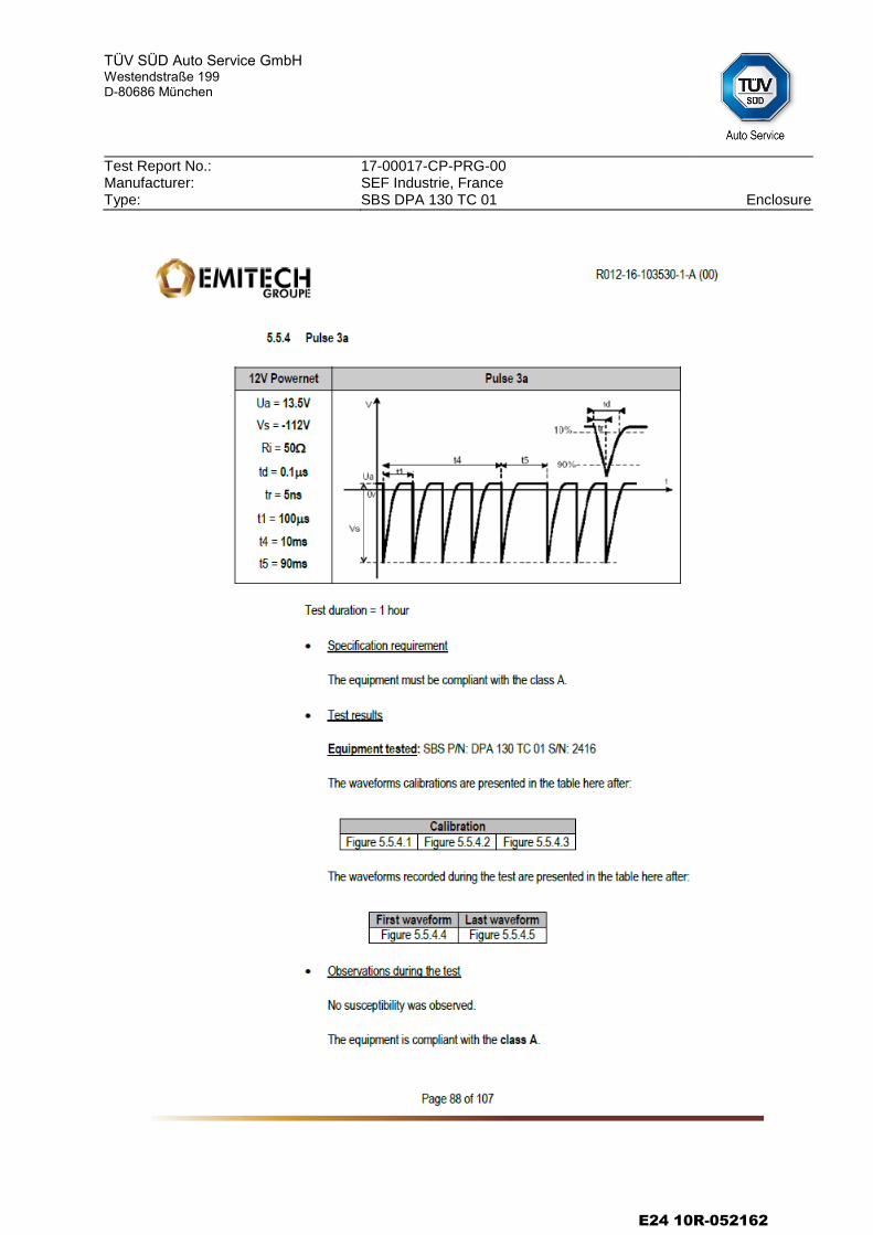
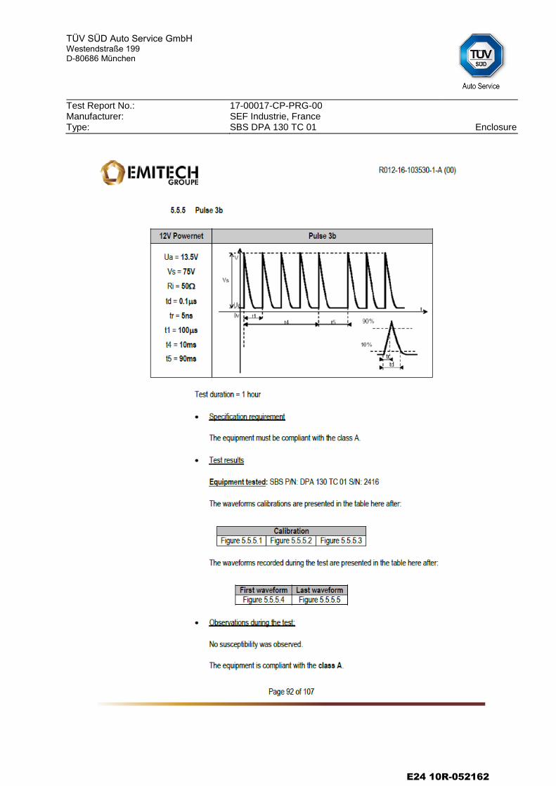
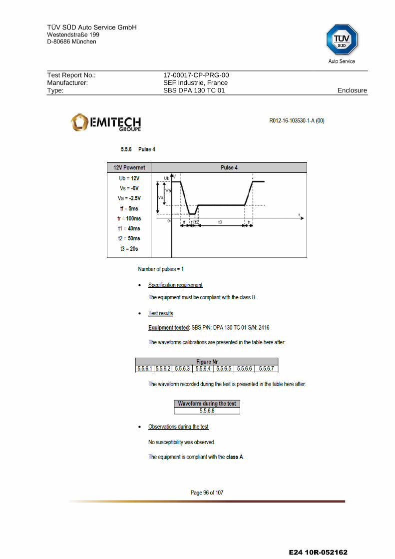
2.4 Immunity of ESA to conducted transient interferences
2.4.1 Method of measurement: Measured as described in annex 10 of ECE-Regulation No. 10.
2.4.2 Results: The ESA has not exhibited any unacceptable malfunction. The claimed functional state was fulfilled during the test. The test was passed.
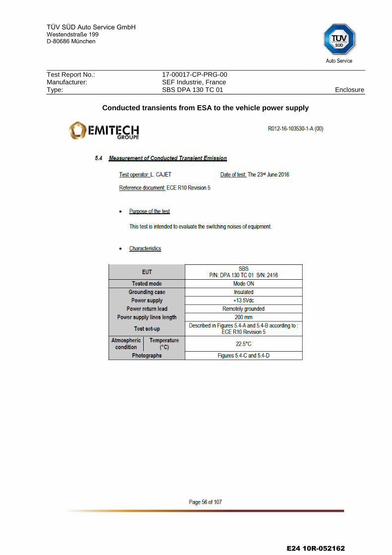
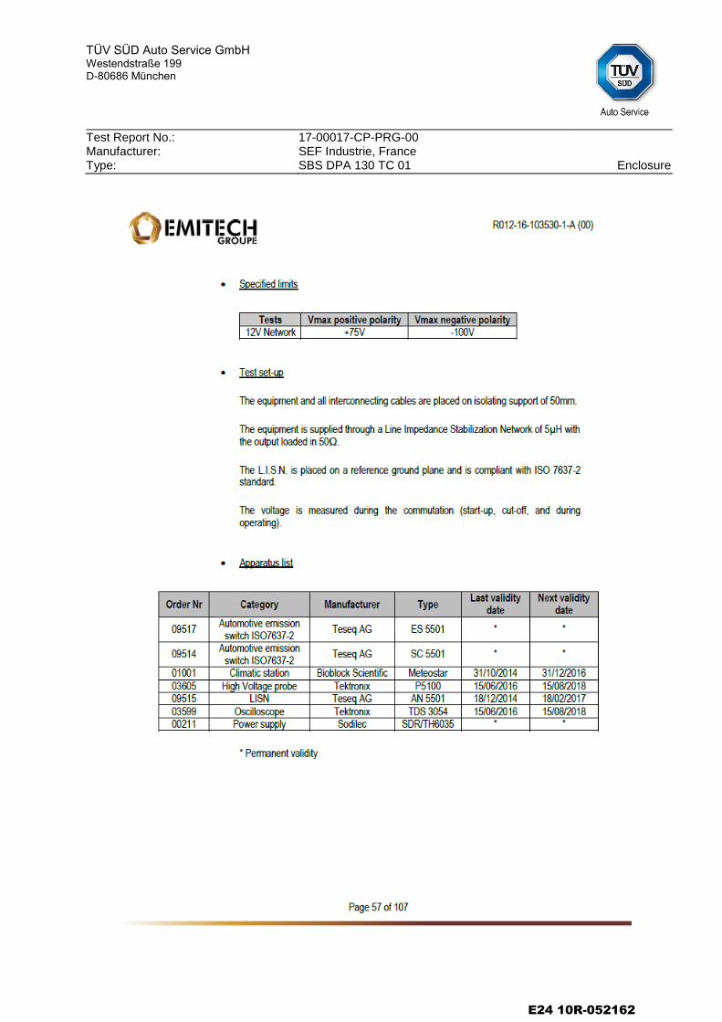
2.5 Conducted transient interferences generated by ESA
2.5.1 Method of measurement: Measured as described in annex 10
of ECE-Regulation No. 10.
2.5.2 Results: The measured values are below the reference limits. The test was passed.
III. Results of the tests
The results of the tests are attached in the diagrams of the enclosure.
IV. Statement of conformity
The information folder as mentioned under No. 1.8 and the type described therein are in compliance with the test specification mentioned above. The worst-case was selected in accordance with document “Preparation of Test Reports”. The test report may be repro-duced and published in full and by the client only. It can be reproduced partially with the written permission of the test laboratory only.
V. Enclosures No.
Enclosure Page(s) Date
1. Test results
25 2016-06-22 and 2016-06-23
2. Information document
16 2016-07-18
E24 10R-052162
TÜV SÜD Auto Service GmbH
Westendstraße 199 D-80686 München
Test Report No.: Manufacturer: Type:
17-00017-CP-PRG-00 SEF Industrie, France SBS DPA 130 TC 01 Page 5/5
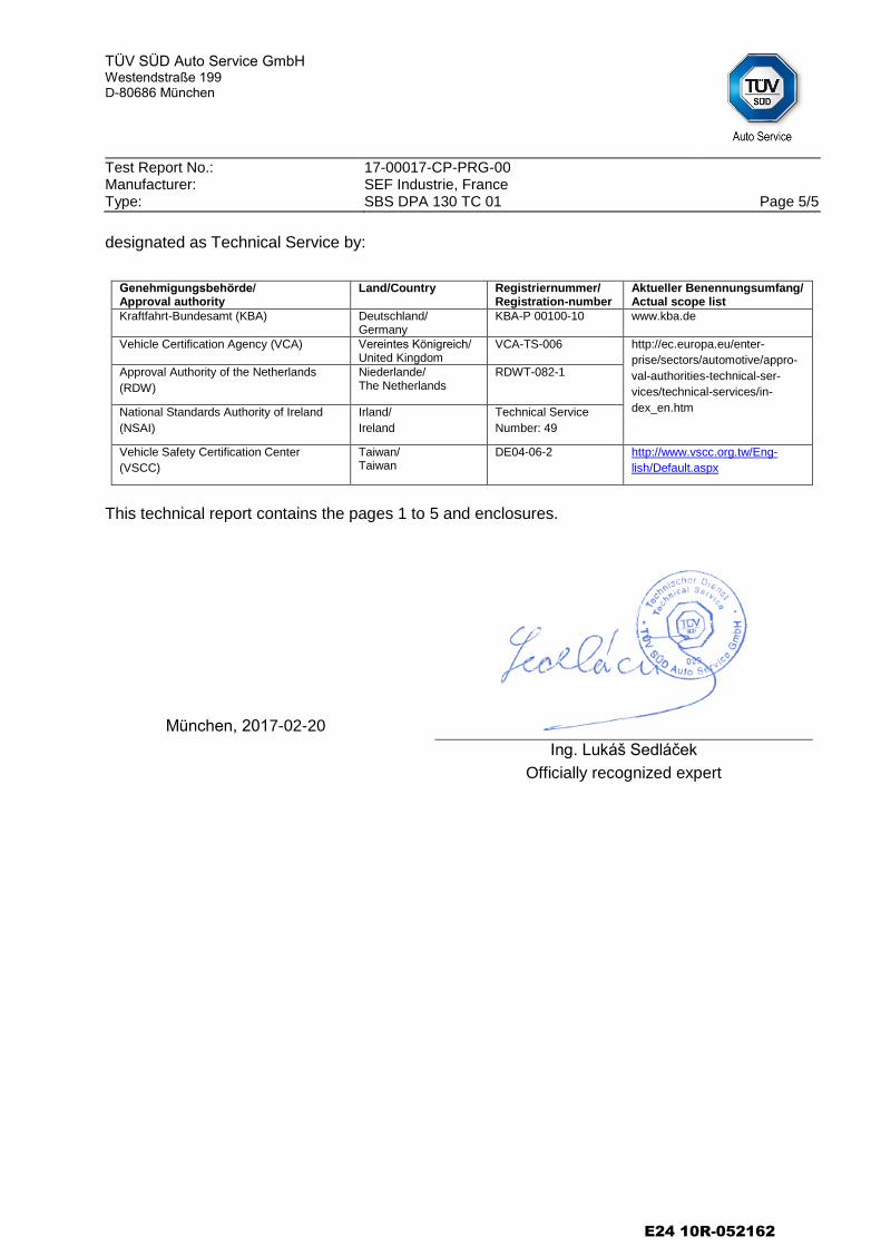
designated as Technical Service by:
Genehmigungsbehörde/ Approval authority
Land/Country Registriernummer/ Registration-number
Aktueller Benennungsumfang/ Actual scope list
Kraftfahrt-Bundesamt (KBA) Deutschland/ Germany
KBA-P 00100-10 www.kba.de
Vehicle Certification Agency (VCA) Vereintes Königreich/ United Kingdom
VCA-TS-006 http://ec.europa.eu/enter-
prise/sectors/automotive/appro-
val-authorities-technical-ser-
vices/technical-services/in-
dex_en.htm
Approval Authority of the Netherlands
(RDW)
Niederlande/ The Netherlands
RDWT-082-1
National Standards Authority of Ireland
(NSAI)
Irland/
Ireland
Technical Service
Number: 49
Vehicle Safety Certification Center
(VSCC)
Taiwan/ Taiwan
DE04-06-2 http://www.vscc.org.tw/Eng-
lish/Default.aspx
This technical report contains the pages 1 to 5 and enclosures.
München, 2017-02-20
Ing. Lukáš Sedláček
Officially recognized expert
E24 10R-052162
TÜV SÜD Auto Service GmbH
Westendstraße 199 D-80686 München
Test Report No.: Manufacturer: Type:
17-00017-CP-PRG-00 SEF Industrie, France SBS DPA 130 TC 01 Enclosure
Enclosure to the
Technical report
17-00017-CP-PRG-00
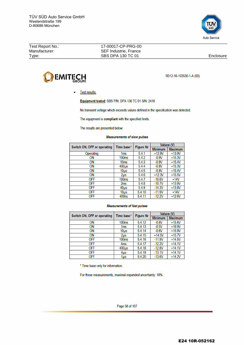
Test results
Contents
Measurement diagrams of the radio interference 30 MHz - 1 GHz 4 Pages
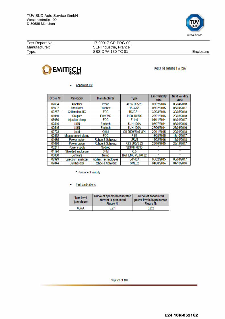
Measurement diagrams for immunity of ESA to electromagnetic radiation (BCI + electric field)
10 Pages
Conducted transients from ESA to the vehicle power supply 3 Pages
Immunity of ESA to conducted transient interferences 8 Pages
E24 10R-052162
TÜV SÜD Auto Service GmbH
Westendstraße 199 D-80686 München
Test Report No.: Manufacturer: Type:
17-00017-CP-PRG-00 SEF Industrie, France SBS DPA 130 TC 01 Enclosure
Measurement diagrams of the radio interference 30 MHz - 1 GHz
E24 10R-052162
TÜV SÜD Auto Service GmbH
Westendstraße 199 D-80686 München
Test Report No.: Manufacturer: Type:
17-00017-CP-PRG-00 SEF Industrie, France SBS DPA 130 TC 01 Enclosure
E24 10R-052162
TÜV SÜD Auto Service GmbH
Westendstraße 199 D-80686 München
Test Report No.: Manufacturer: Type:
17-00017-CP-PRG-00 SEF Industrie, France SBS DPA 130 TC 01 Enclosure
E24 10R-052162
TÜV SÜD Auto Service GmbH
Westendstraße 199 D-80686 München
Test Report No.: Manufacturer: Type:
17-00017-CP-PRG-00 SEF Industrie, France SBS DPA 130 TC 01 Enclosure
E24 10R-052162
TÜV SÜD Auto Service GmbH
Westendstraße 199 D-80686 München
Test Report No.: Manufacturer: Type:
17-00017-CP-PRG-00 SEF Industrie, France SBS DPA 130 TC 01 Enclosure
Measurement diagrams for immunity of ESA to electromagnetic radiation
E24 10R-052162
TÜV SÜD Auto Service GmbH
Westendstraße 199 D-80686 München
Test Report No.: Manufacturer: Type:
17-00017-CP-PRG-00 SEF Industrie, France SBS DPA 130 TC 01 Enclosure
E24 10R-052162
TÜV SÜD Auto Service GmbH
Westendstraße 199 D-80686 München
Test Report No.: Manufacturer: Type:
17-00017-CP-PRG-00 SEF Industrie, France SBS DPA 130 TC 01 Enclosure
E24 10R-052162

TÜV SÜD Auto Service GmbH
Westendstraße 199 D-80686 München
Test Report No.: Manufacturer: Type:
17-00017-CP-PRG-00 SEF Industrie, France SBS DPA 130 TC 01 Enclosure
E24 10R-052162
TÜV SÜD Auto Service GmbH
Westendstraße 199 D-80686 München
Test Report No.: Manufacturer: Type:
17-00017-CP-PRG-00 SEF Industrie, France SBS DPA 130 TC 01 Enclosure
E24 10R-052162
TÜV SÜD Auto Service GmbH
Westendstraße 199 D-80686 München
Test Report No.: Manufacturer: Type:
17-00017-CP-PRG-00 SEF Industrie, France SBS DPA 130 TC 01 Enclosure
E24 10R-052162
TÜV SÜD Auto Service GmbH
Westendstraße 199 D-80686 München
Test Report No.: Manufacturer: Type:
17-00017-CP-PRG-00 SEF Industrie, France SBS DPA 130 TC 01 Enclosure
E24 10R-052162

TÜV SÜD Auto Service GmbH
Westendstraße 199 D-80686 München
Test Report No.: Manufacturer: Type:
17-00017-CP-PRG-00 SEF Industrie, France SBS DPA 130 TC 01 Enclosure
E24 10R-052162

TÜV SÜD Auto Service GmbH
Westendstraße 199 D-80686 München
Test Report No.: Manufacturer: Type:
17-00017-CP-PRG-00 SEF Industrie, France SBS DPA 130 TC 01 Enclosure
E24 10R-052162
TÜV SÜD Auto Service GmbH
Westendstraße 199 D-80686 München
Test Report No.: Manufacturer: Type:
17-00017-CP-PRG-00 SEF Industrie, France SBS DPA 130 TC 01 Enclosure
E24 10R-052162
TÜV SÜD Auto Service GmbH
Westendstraße 199 D-80686 München
Test Report No.: Manufacturer: Type:
17-00017-CP-PRG-00 SEF Industrie, France SBS DPA 130 TC 01 Enclosure
Conducted transients from ESA to the vehicle power supply
E24 10R-052162
TÜV SÜD Auto Service GmbH
Westendstraße 199 D-80686 München
Test Report No.: Manufacturer: Type:
17-00017-CP-PRG-00 SEF Industrie, France SBS DPA 130 TC 01 Enclosure
E24 10R-052162
TÜV SÜD Auto Service GmbH
Westendstraße 199 D-80686 München
Test Report No.: Manufacturer: Type:
17-00017-CP-PRG-00 SEF Industrie, France SBS DPA 130 TC 01 Enclosure
E24 10R-052162
TÜV SÜD Auto Service GmbH
Westendstraße 199 D-80686 München
Test Report No.: Manufacturer: Type:
17-00017-CP-PRG-00 SEF Industrie, France SBS DPA 130 TC 01 Enclosure
Immunity of ESA to conducted transient interferences
E24 10R-052162
TÜV SÜD Auto Service GmbH
Westendstraße 199 D-80686 München
Test Report No.: Manufacturer: Type:
17-00017-CP-PRG-00 SEF Industrie, France SBS DPA 130 TC 01 Enclosure
E24 10R-052162
TÜV SÜD Auto Service GmbH
Westendstraße 199 D-80686 München
Test Report No.: Manufacturer: Type:
17-00017-CP-PRG-00 SEF Industrie, France SBS DPA 130 TC 01 Enclosure
E24 10R-052162
TÜV SÜD Auto Service GmbH
Westendstraße 199 D-80686 München
Test Report No.: Manufacturer: Type:
17-00017-CP-PRG-00 SEF Industrie, France SBS DPA 130 TC 01 Enclosure
E24 10R-052162
TÜV SÜD Auto Service GmbH
Westendstraße 199 D-80686 München
Test Report No.: Manufacturer: Type:
17-00017-CP-PRG-00 SEF Industrie, France SBS DPA 130 TC 01 Enclosure
E24 10R-052162
TÜV SÜD Auto Service GmbH
Westendstraße 199 D-80686 München
Test Report No.: Manufacturer: Type:
17-00017-CP-PRG-00 SEF Industrie, France SBS DPA 130 TC 01 Enclosure
E24 10R-052162
TÜV SÜD Auto Service GmbH
Westendstraße 199 D-80686 München
Test Report No.: Manufacturer: Type:
17-00017-CP-PRG-00 SEF Industrie, France SBS DPA 130 TC 01 Enclosure
E24 10R-052162
TÜV SÜD Auto Service GmbH
Westendstraße 199 D-80686 München
Test Report No.: Manufacturer: Type:
17-00017-CP-PRG-00 SEF Industrie, France SBS DPA 130 TC 01 Enclosure
E24 10R-052162
Datum / date: 18 July 2016
1/2
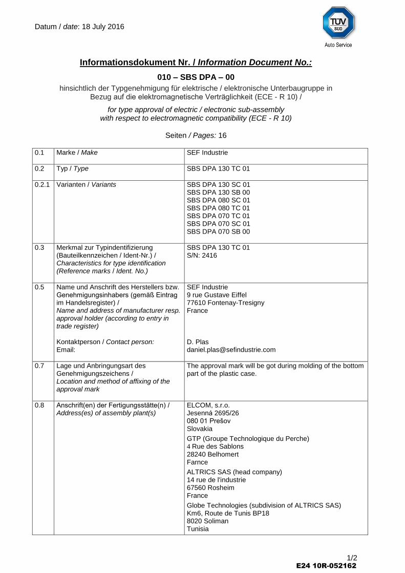
Informationsdokument Nr. / Information Document No.:
010 – SBS DPA – 00
hinsichtlich der Typgenehmigung für elektrische / elektronische Unterbaugruppe in Bezug auf die elektromagnetische Verträglichkeit (ECE - R 10) /
for type approval of electric / electronic sub-assembly with respect to electromagnetic compatibility (ECE - R 10)
Seiten / Pages: 16
0.1 Marke / Make
SEF Industrie
0.2 Typ / Type
SBS DPA 130 TC 01
0.2.1 Varianten / Variants SBS DPA 130 SC 01 SBS DPA 130 SB 00 SBS DPA 080 SC 01 SBS DPA 080 TC 01 SBS DPA 070 TC 01 SBS DPA 070 SC 01 SBS DPA 070 SB 00
0.3 Merkmal zur Typindentifizierung (Bauteilkennzeichen / Ident-Nr.) / Characteristics for type identification (Reference marks / Ident. No.)
SBS DPA 130 TC 01 S/N: 2416
0.5 Name und Anschrift des Herstellers bzw. Genehmigungsinhabers (gemäß Eintrag im Handelsregister) / Name and address of manufacturer resp. approval holder (according to entry in trade register) Kontaktperson / Contact person: Email:
SEF Industrie 9 rue Gustave Eiffel 77610 Fontenay-Tresigny France D. Plas [email protected]
0.7 Lage und Anbringungsart des Genehmigungszeichens / Location and method of affixing of the approval mark
The approval mark will be got during molding of the bottom part of the plastic case.
0.8 Anschrift(en) der Fertigungsstätte(n) / Address(es) of assembly plant(s)
ELCOM, s.r.o. Jesenná 2695/26 080 01 Prešov Slovakia
GTP (Groupe Technologique du Perche) 4 Rue des Sablons 28240 Belhomert Farnce
ALTRICS SAS (head company) 14 rue de l'industrie 67560 Rosheim France
Globe Technologies (subdivision of ALTRICS SAS) Km6, Route de Tunis BP18 8020 Soliman Tunisia
E24 10R-052162
Datum / date: 18 July 2016
2/2
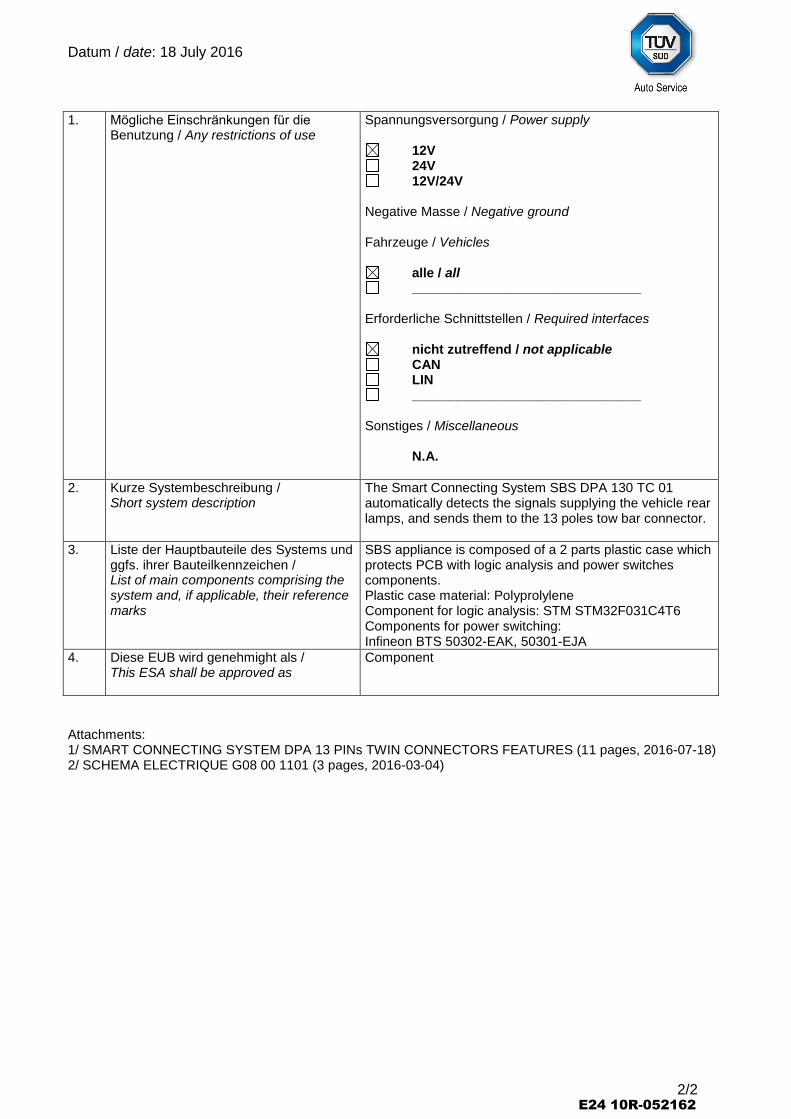
1. Mögliche Einschränkungen für die Benutzung / Any restrictions of use
Spannungsversorgung / Power supply
12V 24V 12V/24V
Negative Masse / Negative ground Fahrzeuge / Vehicles
alle / all _______________________________
Erforderliche Schnittstellen / Required interfaces
nicht zutreffend / not applicable CAN LIN _______________________________
Sonstiges / Miscellaneous N.A.
2. Kurze Systembeschreibung / Short system description
The Smart Connecting System SBS DPA 130 TC 01 automatically detects the signals supplying the vehicle rear lamps, and sends them to the 13 poles tow bar connector.
3. Liste der Hauptbauteile des Systems und ggfs. ihrer Bauteilkennzeichen / List of main components comprising the system and, if applicable, their reference marks
SBS appliance is composed of a 2 parts plastic case which protects PCB with logic analysis and power switches components. Plastic case material: Polyprolylene Component for logic analysis: STM STM32F031C4T6 Components for power switching: Infineon BTS 50302-EAK, 50301-EJA
4. Diese EUB wird genehmight als / This ESA shall be approved as
Component
Attachments: 1/ SMART CONNECTING SYSTEM DPA 13 PINs TWIN CONNECTORS FEATURES (11 pages, 2016-07-18) 2/ SCHEMA ELECTRIQUE G08 00 1101 (3 pages, 2016-03-04)
E24 10R-052162
Rev. Date Nom
SBS DPA 130 TC 01 description document A 18/07/2016 PLAS
Page p. 1 Total pages: 11 A62001100
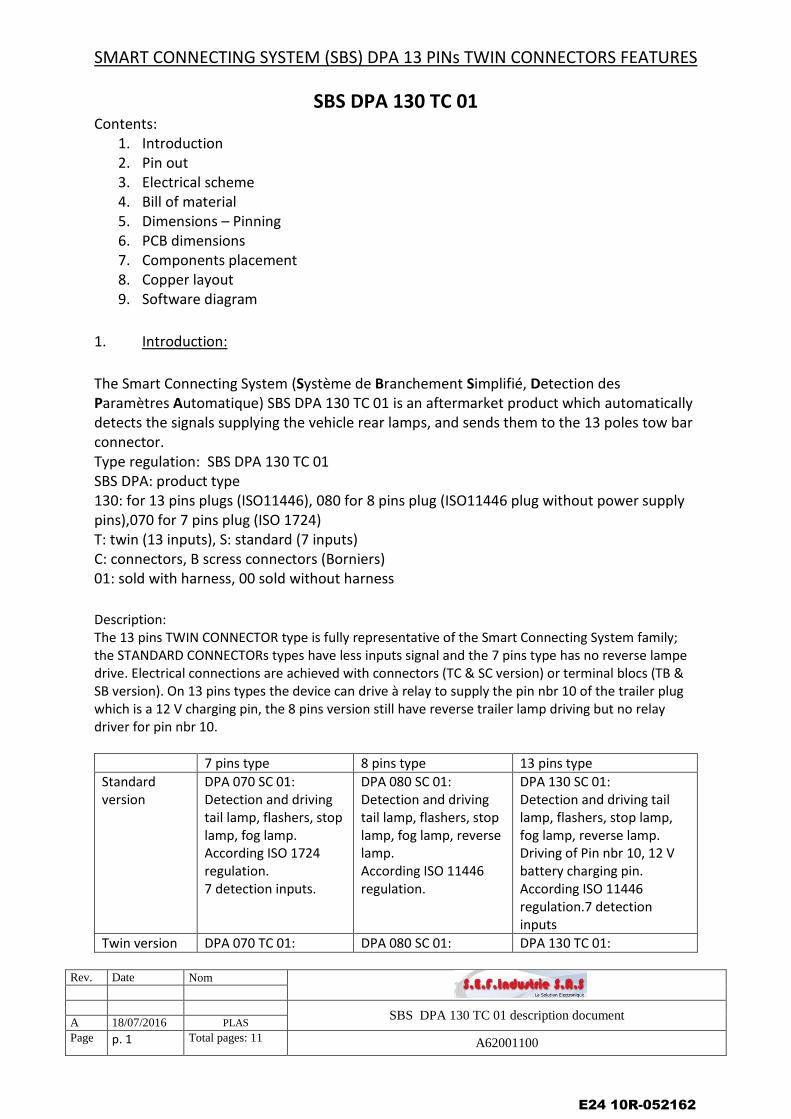
SMART CONNECTING SYSTEM (SBS) DPA 13 PINs TWIN CONNECTORS FEATURES
SBS DPA 130 TC 01 Contents:
1. Introduction 2. Pin out 3. Electrical scheme 4. Bill of material 5. Dimensions – Pinning 6. PCB dimensions 7. Components placement 8. Copper layout 9. Software diagram
1. Introduction:
The Smart Connecting System (Système de Branchement Simplifié, Detection des Paramètres Automatique) SBS DPA 130 TC 01 is an aftermarket product which automatically detects the signals supplying the vehicle rear lamps, and sends them to the 13 poles tow bar connector. Type regulation: SBS DPA 130 TC 01 SBS DPA: product type 130: for 13 pins plugs (ISO11446), 080 for 8 pins plug (ISO11446 plug without power supply pins),070 for 7 pins plug (ISO 1724) T: twin (13 inputs), S: standard (7 inputs) C: connectors, B scress connectors (Borniers) 01: sold with harness, 00 sold without harness
Description: The 13 pins TWIN CONNECTOR type is fully representative of the Smart Connecting System family; the STANDARD CONNECTORs types have less inputs signal and the 7 pins type has no reverse lampe drive. Electrical connections are achieved with connectors (TC & SC version) or terminal blocs (TB & SB version). On 13 pins types the device can drive à relay to supply the pin nbr 10 of the trailer plug which is a 12 V charging pin, the 8 pins version still have reverse trailer lamp driving but no relay driver for pin nbr 10.
7 pins type 8 pins type 13 pins type
Standard version
DPA 070 SC 01: Detection and driving tail lamp, flashers, stop lamp, fog lamp. According ISO 1724 regulation. 7 detection inputs.
DPA 080 SC 01: Detection and driving tail lamp, flashers, stop lamp, fog lamp, reverse lamp. According ISO 11446 regulation.
DPA 130 SC 01: Detection and driving tail lamp, flashers, stop lamp, fog lamp, reverse lamp. Driving of Pin nbr 10, 12 V battery charging pin. According ISO 11446 regulation.7 detection inputs
Twin version DPA 070 TC 01: DPA 080 SC 01: DPA 130 TC 01:
E24 10R-052162
Rev. Date Nom
SBS DPA 130 TC 01 description document A 18/07/2016 PLAS
Page p. 2 Total pages: 11 A62001100
Detection and driving tail lamp, flashers, stop lamp, fog lamp. According ISO 1724 regulation 13 detection inputs.
Detection and driving tail lamp, flashers, stop lamp, fog lamp, reverse lamp. According ISO 11446 regulation. 13 detection inputs
Detection and driving tail lamp, flashers, stop lamp, fog lamp, reverse lamp. Driving of Pin nbr 10, 12 V battery charging pin. According ISO 11446 regulation. 7 detection inputs
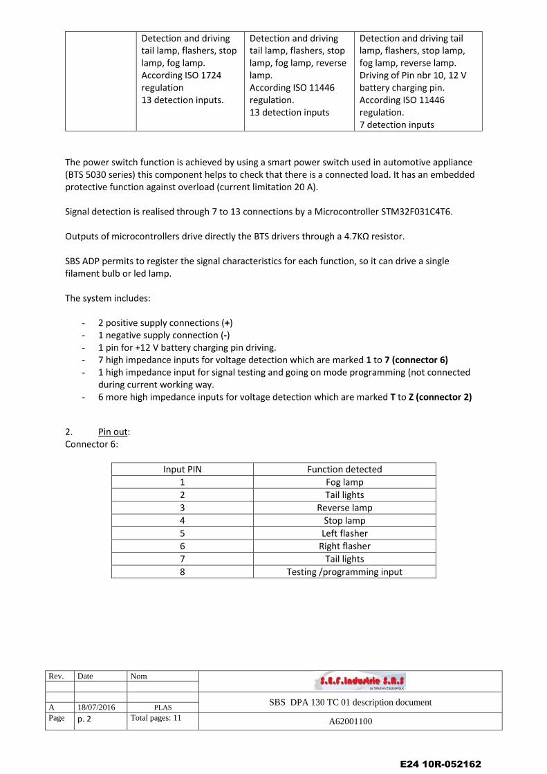
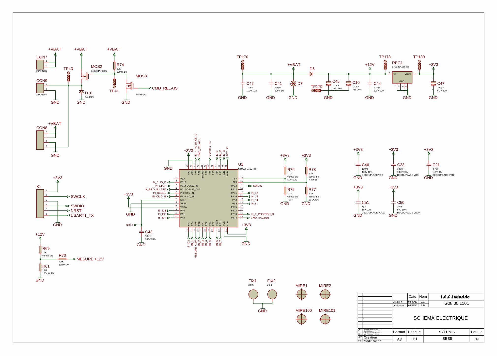
The power switch function is achieved by using a smart power switch used in automotive appliance (BTS 5030 series) this component helps to check that there is a connected load. It has an embedded protective function against overload (current limitation 20 A). Signal detection is realised through 7 to 13 connections by a Microcontroller STM32F031C4T6. Outputs of microcontrollers drive directly the BTS drivers through a 4.7KΩ resistor. SBS ADP permits to register the signal characteristics for each function, so it can drive a single filament bulb or led lamp. The system includes:
- 2 positive supply connections (+) - 1 negative supply connection (-) - 1 pin for +12 V battery charging pin driving. - 7 high impedance inputs for voltage detection which are marked 1 to 7 (connector 6) - 1 high impedance input for signal testing and going on mode programming (not connected
during current working way. - 6 more high impedance inputs for voltage detection which are marked T to Z (connector 2)
2. Pin out: Connector 6:
Input PIN Function detected
1 Fog lamp
2 Tail lights
3 Reverse lamp
4 Stop lamp
5 Left flasher
6 Right flasher
7 Tail lights
8 Testing /programming input
E24 10R-052162
Rev. Date Nom
SBS DPA 130 TC 01 description document A 18/07/2016 PLAS
Page p. 3 Total pages: 11 A62001100
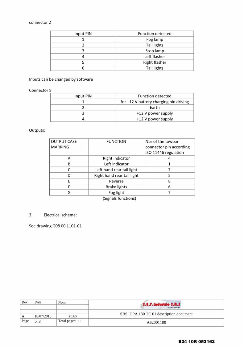
connector 2
Input PIN Function detected
1 Fog lamp
2 Tail lights
3 Stop lamp
4 Left flasher
5 Right flasher
6 Tail lights
Inputs can be changed by software Connector 8
Input PIN Function detected
1 for +12 V battery charging pin driving
2 Earth
3 +12 V power supply
4 +12 V power supply
Outputs:
OUTPUT CASE MARKING
FUNCTION
Nbr of the towbar connector pin according ISO 11446 regulation
A Right indicator 4
B Left indicator 1
C Left hand rear tail light 7
D Right hand rear tail light 5
E Reverse 8
F Brake lights 6
G Fog light 7
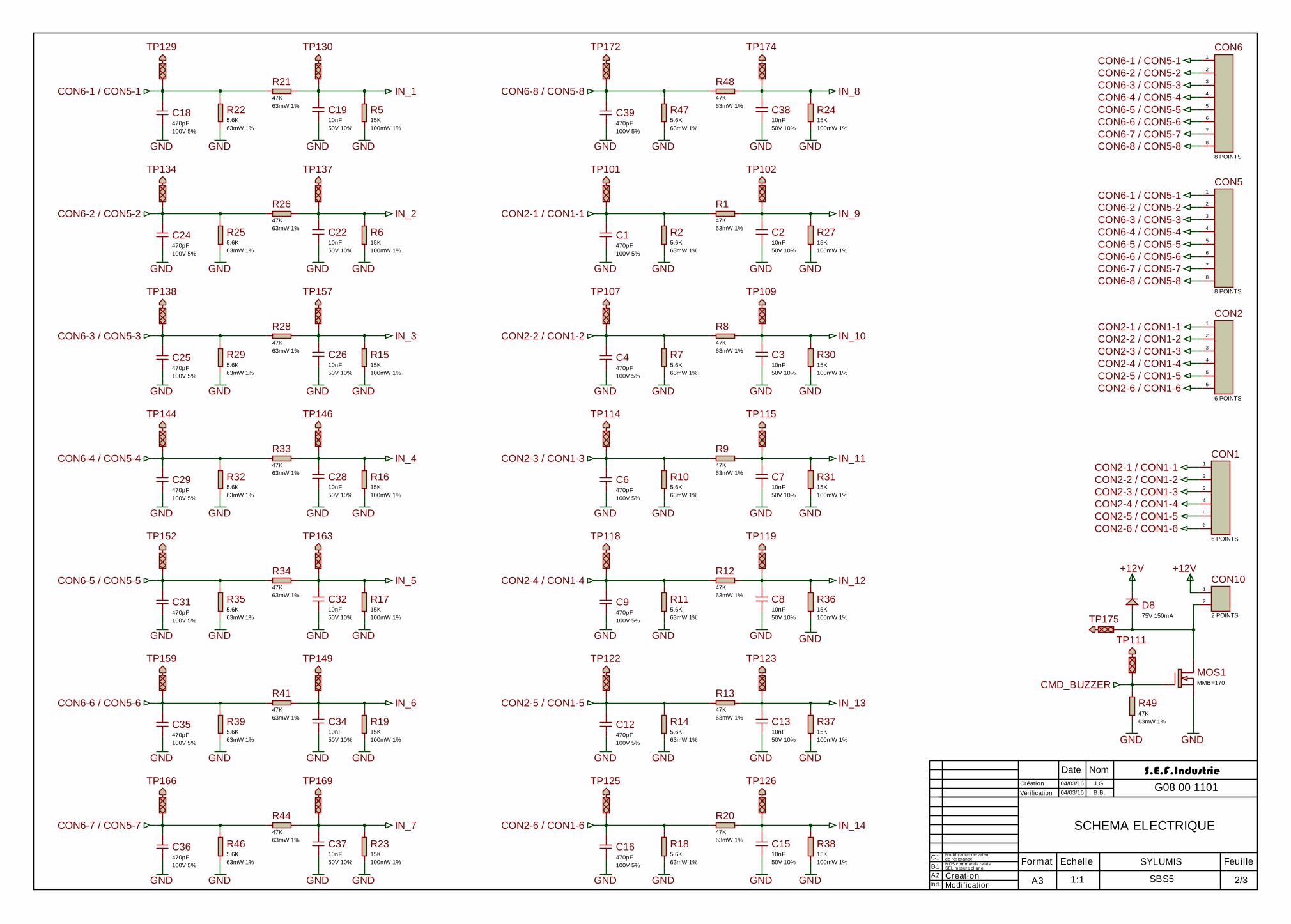
(Signals functions) 3. Electrical scheme: See drawing G08 00 1101-C1
E24 10R-052162
Rev. Date Nom
SBS DPA 130 TC 01 description document A 18/07/2016 PLAS
Page p. 4 Total pages: 11 A62001100
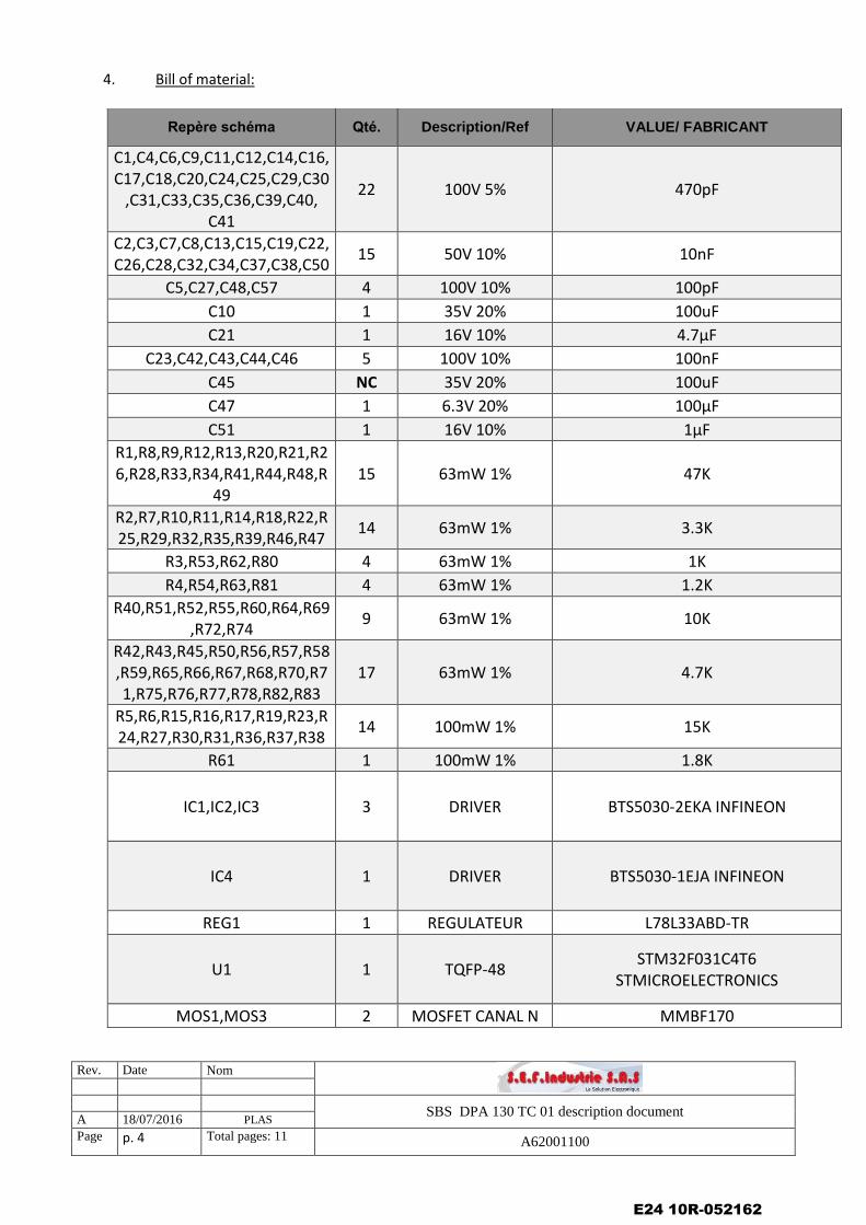
4. Bill of material:
Repère schéma Qté. Description/Ref VALUE/ FABRICANT
C1,C4,C6,C9,C11,C12,C14,C16,C17,C18,C20,C24,C25,C29,C30
,C31,C33,C35,C36,C39,C40, C41
22 100V 5% 470pF
C2,C3,C7,C8,C13,C15,C19,C22,C26,C28,C32,C34,C37,C38,C50
15 50V 10% 10nF
C5,C27,C48,C57 4 100V 10% 100pF
C10 1 35V 20% 100uF
C21 1 16V 10% 4.7µF
C23,C42,C43,C44,C46 5 100V 10% 100nF
C45 NC 35V 20% 100uF
C47 1 6.3V 20% 100µF
C51 1 16V 10% 1µF
R1,R8,R9,R12,R13,R20,R21,R26,R28,R33,R34,R41,R44,R48,R
49 15 63mW 1% 47K
R2,R7,R10,R11,R14,R18,R22,R25,R29,R32,R35,R39,R46,R47
14 63mW 1% 3.3K
R3,R53,R62,R80 4 63mW 1% 1K
R4,R54,R63,R81 4 63mW 1% 1.2K
R40,R51,R52,R55,R60,R64,R69,R72,R74
9 63mW 1% 10K
R42,R43,R45,R50,R56,R57,R58,R59,R65,R66,R67,R68,R70,R71,R75,R76,R77,R78,R82,R83
17 63mW 1% 4.7K
R5,R6,R15,R16,R17,R19,R23,R24,R27,R30,R31,R36,R37,R38
14 100mW 1% 15K
R61 1 100mW 1% 1.8K
IC1,IC2,IC3 3 DRIVER BTS5030-2EKA INFINEON
IC4 1 DRIVER BTS5030-1EJA INFINEON
REG1 1 REGULATEUR L78L33ABD-TR
U1 1 TQFP-48 STM32F031C4T6
STMICROELECTRONICS
MOS1,MOS3 2 MOSFET CANAL N MMBF170
E24 10R-052162
Rev. Date Nom
SBS DPA 130 TC 01 description document A 18/07/2016 PLAS
Page p. 5 Total pages: 11 A62001100
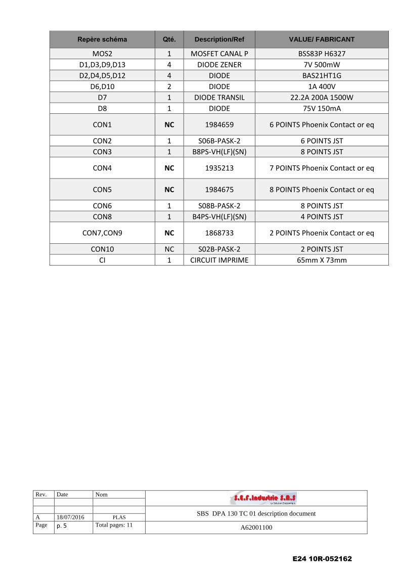
Repère schéma Qté. Description/Ref VALUE/ FABRICANT
MOS2 1 MOSFET CANAL P BSS83P H6327
D1,D3,D9,D13 4 DIODE ZENER 7V 500mW
D2,D4,D5,D12 4 DIODE BAS21HT1G
D6,D10 2 DIODE 1A 400V
D7 1 DIODE TRANSIL 22.2A 200A 1500W
D8 1 DIODE 75V 150mA
CON1 NC 1984659 6 POINTS Phoenix Contact or eq
CON2 1 S06B-PASK-2 6 POINTS JST
CON3 1 B8PS-VH(LF)(SN) 8 POINTS JST
CON4 NC 1935213 7 POINTS Phoenix Contact or eq
CON5 NC 1984675 8 POINTS Phoenix Contact or eq
CON6 1 S08B-PASK-2 8 POINTS JST
CON8 1 B4PS-VH(LF)(SN) 4 POINTS JST
CON7,CON9 NC 1868733 2 POINTS Phoenix Contact or eq
CON10 NC S02B-PASK-2 2 POINTS JST
CI 1 CIRCUIT IMPRIME 65mm X 73mm
E24 10R-052162
Rev. Date Nom
SBS DPA 130 TC 01 description document A 18/07/2016 PLAS
Page p. 6 Total pages: 11 A62001100
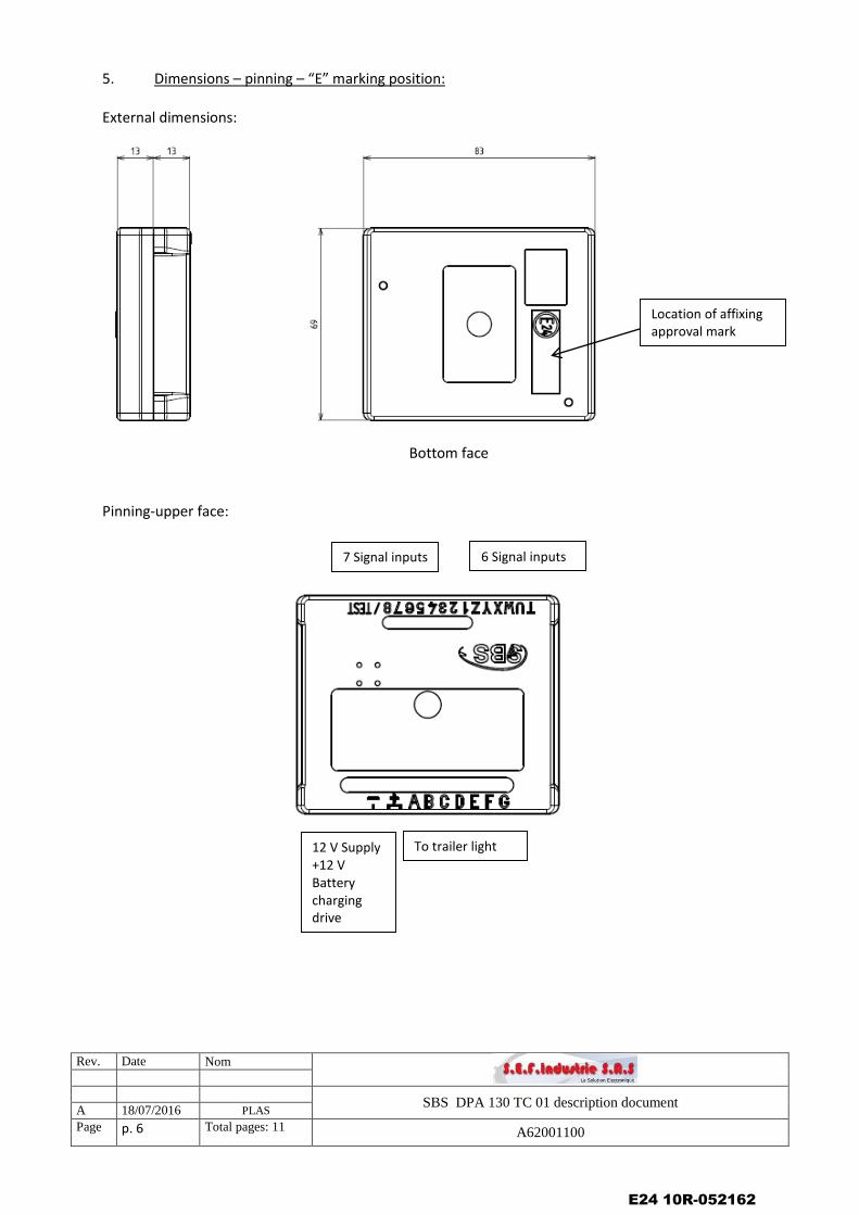
5. Dimensions – pinning – “E” marking position: External dimensions:
Bottom face Pinning-upper face:
To trailer light
6 Signal inputs 7 Signal inputs
12 V Supply +12 V Battery charging drive
Location of affixing approval mark
E24 10R-052162
Rev. Date Nom
SBS DPA 130 TC 01 description document A 18/07/2016 PLAS
Page p. 7 Total pages: 11 A62001100
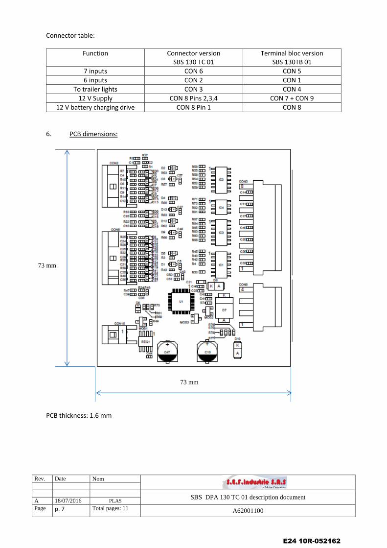
Connector table:
Function Connector version SBS 130 TC 01
Terminal bloc version SBS 130TB 01
7 inputs CON 6 CON 5
6 inputs CON 2 CON 1
To trailer lights CON 3 CON 4
12 V Supply CON 8 Pins 2,3,4 CON 7 + CON 9
12 V battery charging drive CON 8 Pin 1 CON 8
6. PCB dimensions:
PCB thickness: 1.6 mm
73 mm
73 mm
E24 10R-052162
Rev. Date Nom
SBS DPA 130 TC 01 description document A 18/07/2016 PLAS
Page p. 8 Total pages: 11 A62001100
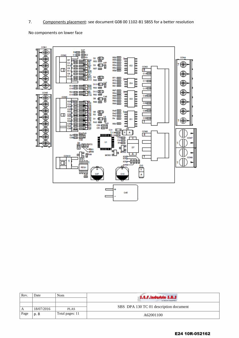
7. Components placement: see document G08 00 1102-B1 SBS5 for a better resolution No components on lower face
E24 10R-052162
Rev. Date Nom
SBS DPA 130 TC 01 description document A 18/07/2016 PLAS
Page p. 9 Total pages: 11 A62001100
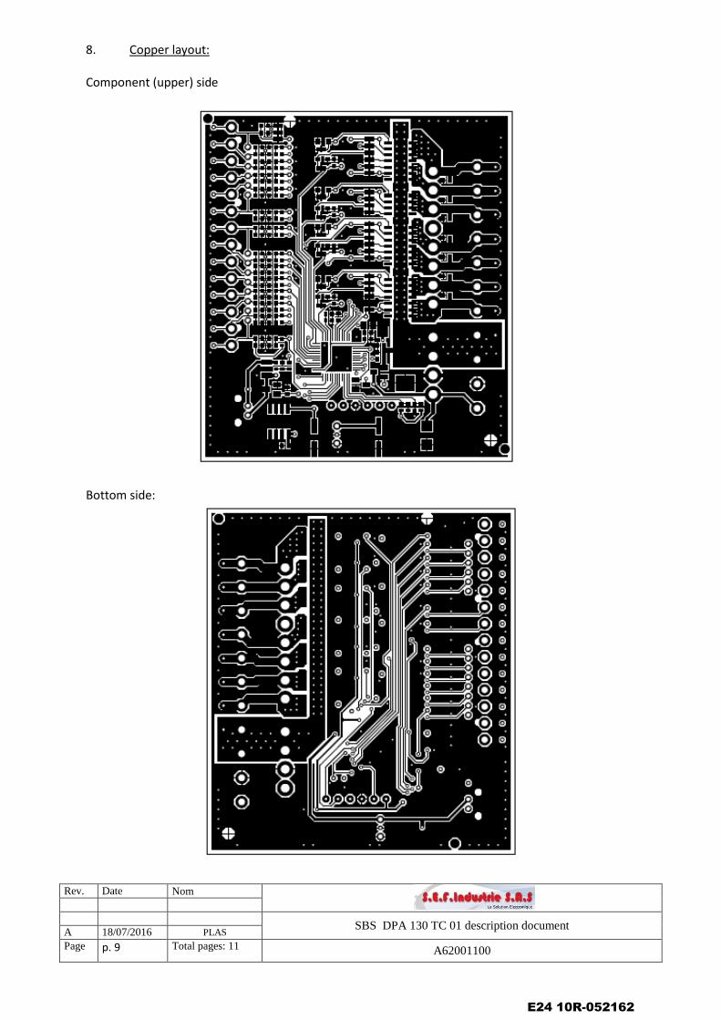
8. Copper layout: Component (upper) side
Bottom side:
E24 10R-052162
Rev. Date Nom
SBS DPA 130 TC 01 description document A 18/07/2016 PLAS
Page p. 10 Total pages: 11 A62001100
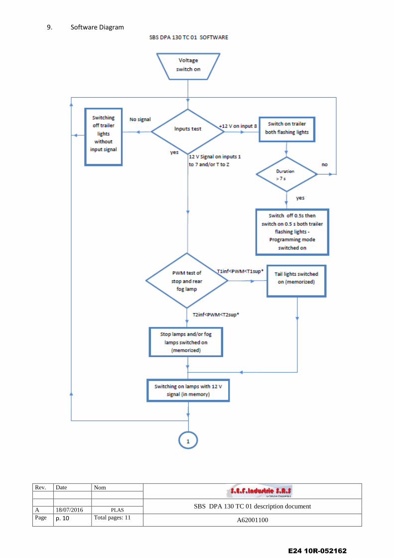
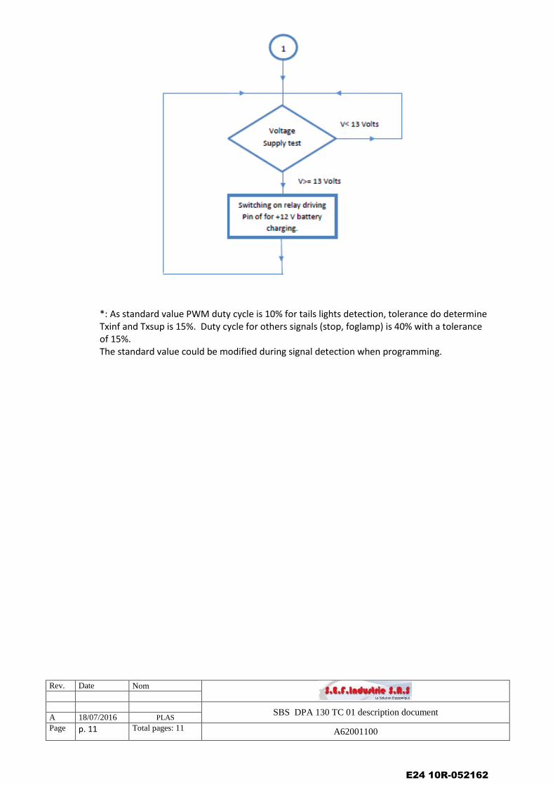
9. Software Diagram
E24 10R-052162
Rev. Date Nom
SBS DPA 130 TC 01 description document A 18/07/2016 PLAS
Page p. 11 Total pages: 11 A62001100
*: As standard value PWM duty cycle is 10% for tails lights detection, tolerance do determine Txinf and Txsup is 15%. Duty cycle for others signals (stop, foglamp) is 40% with a tolerance of 15%. The standard value could be modified during signal detection when programming.
E24 10R-052162
SBS5Ind.
G08 00 1101J.G.
1/3
04/03/16
04/03/16
SCHEMA ELECTRIQUE
S.E.F.IndustrieCréation
Vérification
Date Nom
Format Echelle Feuille
Modification
A2 CreationA3 1:1
SYLUMIS
B.B.
B1MOS commande relaisSEL mesure cligno
C1Modification de valeurde résistance
GND
+
-
C47100µF
6.3V 20%
GND
+3V3
C44100nF
100V 10%
GND
C42100nF
100V 10%
GND
C41470pF
100V 5%
GND
+12V
D7
GND
+VBATD6
TP170 TP178 TP180
FIX12mm
FIX22mm
GND
MIRE1 MIRE2
1
2
3
4
CON8
GND
+VBAT
1
2
CON9
2 POINTS
1
2
CON7
2 POINTS
+VBAT
GND
GND
VIN8
VOUT1
2 3 76
REG1L78L33ABD-TR
MIRE100 MIRE101
+
C45100uF
35V 20%
+
C10100uF
35V 20%
GND
TP179
1
2
3
4
5
6
X1
GND
+3V3
NRST
SWCLK
SWDIO
VBAT1
PC132
PC14-OSC32_IN3
PC15-OSC32_OUT4
PF0-OSC_IN5
PF1-OSC_IN6
NRST7
VSSA8
VDDA9
PA010
PA111
PA212
PA
313
PA
414
PA
515
PA
616
PA1233
PA1334
PF635
PF736
PA
14
37
PA
15
38
PB
339
PB
440
PB
541
PB
642
PB
743
BO
OT
044
PB
845
PB
946
VS
S47
VD
D48
PA
717
PB
018
PB
119
PB
220
PB
10
21
PB
11
22
VS
S23
VD
D24
PB1225
PB1326
PB1427
PB1528
PA829
PA930
PA1031
PA1132
U1STM32F031C4T6
GND
GND
+3V3
+3V3
D101A 400V
+VBAT
CMD_RELAIS
SWDIO
TP41
C23100nF
100V 10%
DECOUPLAGE VDD
+3V3
GND
GND
+3V3
C46100nF
100V 10%
DECOUPLAGE VDD
+3V3
GND
+VBAT
MOS2BSS83P H6327
GND
TP43R7410K
63mW 1%
R611.8K
100mW 1%
R6910K
63mW 1% R70
4.7K
63mW 1%
GND
MESURE +12V
+12V
C5010nF
50V 10%
DECOUPLAGE VDDA
C511µF
16V 10%
DECOUPLAGE VDDA
+3V3+3V3
GNDGND
C214.7µF
16V 10%
DECOUPLAGE VDD
+3V3
GND
ME
SU
RE
+12V
CMD_BUZZER
IN_1
IN_2
IN_3
IN_4
IN_5
IN_6
IN_7
IN_12
IN_13
IN_14
IN_8
IN_9
IN_10
IN_11
IS_IC1
IS_IC3
IS_IC4
IS_IC
2
IN_CLIG_D
IN_STOP
IN_BROUILLARD
IN_RECUL
IN_CLIG_G
IN_F_POSITION_D
IN_F
_P
OS
ITIO
N_G
CM
D_R
EL
AIS
NRSTS
WC
LK
USART1_TX
US
AR
T1_T
X
C43100nF
100V 10%
GND
R754.7K
63mW 1%
TWIN
R764.7K
63mW 1%
NORMAL
R774.7K
63mW 1%
13 VOIES
R784.7K
63mW 1%
7 VOIES
+3V3 +3V3
GND GND
MOS3
MMBF170
GND
SBS5Ind.
G08 00 1101J.G.
2/3
04/03/16
04/03/16
SCHEMA ELECTRIQUE
S.E.F.IndustrieCréation
Vérification
Date Nom
Format Echelle Feuille
Modification
A2 CreationA3 1:1
SYLUMIS
B.B.
B1MOS commande relaisSEL mesure cligno
C1Modification de valeurde résistance
C1910nF
50V 10%
GND
IN_1R21
47K
63mW 1%R225.6K
63mW 1%
GND
C18470pF
100V 5%
GND
C2210nF
50V 10%
GND
IN_2R26
47K
63mW 1%R255.6K
63mW 1%
GND
C24470pF
100V 5%
GND
C2610nF
50V 10%
GND
IN_3R28
47K
63mW 1%R295.6K
63mW 1%
GND
C25470pF
100V 5%
GND
C2810nF
50V 10%
GND
IN_4R33
47K
63mW 1%R325.6K
63mW 1%
GND
C29470pF
100V 5%
GND
C3210nF
50V 10%
GND
IN_5R34
47K
63mW 1%R355.6K
63mW 1%
GND
C31470pF
100V 5%
GND
C3410nF
50V 10%
GND
IN_6R41
47K
63mW 1%R395.6K
63mW 1%
GND
C35470pF
100V 5%
GND
C3710nF
50V 10%
GND
IN_7R44
47K
63mW 1%R465.6K
63mW 1%
GND
C36470pF
100V 5%
GND
C3810nF
50V 10%
GND
IN_8R48
47K
63mW 1%R475.6K
63mW 1%
GND
C39470pF
100V 5%
GND
C210nF
50V 10%
GND
IN_9R1
47K
63mW 1%R25.6K
63mW 1%
GND
C1470pF
100V 5%
GND
C310nF
50V 10%
GND
IN_10R8
47K
63mW 1%R75.6K
63mW 1%
GND
C4470pF
100V 5%
GND
C710nF
50V 10%
GND
IN_11R9
47K
63mW 1%R105.6K
63mW 1%
GND
C6470pF
100V 5%
GND
C810nF
50V 10%
GND
IN_12R12
47K
63mW 1%R115.6K
63mW 1%
GND
C9470pF
100V 5%
GND
C1310nF
50V 10%
GND
IN_13R13
47K
63mW 1%R145.6K
63mW 1%
GND
C12470pF
100V 5%
GND
C1510nF
50V 10%
GND
IN_14R20
47K
63mW 1%R185.6K
63mW 1%
GND
C16470pF
100V 5%
GND
TP129 TP130
TP134 TP137
TP138 TP157
TP144 TP146
TP152 TP163
TP159 TP149
TP166 TP169
TP172 TP174
TP101 TP102
TP107 TP109
TP114 TP115
TP118 TP119
TP122 TP123
TP125 TP126
1
2
3
4
5
6
7
8
CON6
8 POINTS
1
2
3
4
5
6
CON2
6 POINTS
1
2
3
4
5
6
7
8
CON5
8 POINTS
1
2
3
4
5
6
CON1
6 POINTS
+12V
D875V 150mA
TP175
MOS1MMBF170
GND
R4947K
63mW 1%
GND
TP111
R515K
100mW 1%
R615K
100mW 1%
R1515K
100mW 1%
R1615K
100mW 1%
R1715K
100mW 1%
R1915K
100mW 1%
R2315K
100mW 1%
R2415K
100mW 1%
R2715K
100mW 1%
R3015K
100mW 1%
R3115K
100mW 1%
R3615K
100mW 1%
R3715K
100mW 1%
R3815K
100mW 1%
GND
GND
GND
GND
GND
GND
GNDGND
GND
GND
GND
GND
GND
GND
CMD_BUZZER
CON6-1 / CON5-1
CON6-2 / CON5-2
CON6-3 / CON5-3
CON6-4 / CON5-4
CON6-5 / CON5-5
CON6-6 / CON5-6
CON6-7 / CON5-7
CON6-8 / CON5-8
CON2-1 / CON1-1
CON2-2 / CON1-2
CON2-3 / CON1-3
CON2-4 / CON1-4
CON2-5 / CON1-5
CON2-6 / CON1-6
CON6-1 / CON5-1
CON6-2 / CON5-2
CON6-3 / CON5-3
CON6-4 / CON5-4
CON6-5 / CON5-5
CON6-6 / CON5-6
CON6-7 / CON5-7
CON6-8 / CON5-8
CON6-1 / CON5-1
CON6-2 / CON5-2
CON6-3 / CON5-3
CON6-4 / CON5-4
CON6-5 / CON5-5
CON6-6 / CON5-6
CON6-7 / CON5-7
CON6-8 / CON5-8
CON2-1 / CON1-1
CON2-2 / CON1-2
CON2-3 / CON1-3
CON2-4 / CON1-4
CON2-5 / CON1-5
CON2-6 / CON1-6
CON2-1 / CON1-1
CON2-2 / CON1-2
CON2-3 / CON1-3
CON2-4 / CON1-4
CON2-5 / CON1-5
CON2-6 / CON1-6
1
2
CON10
2 POINTS
+12V
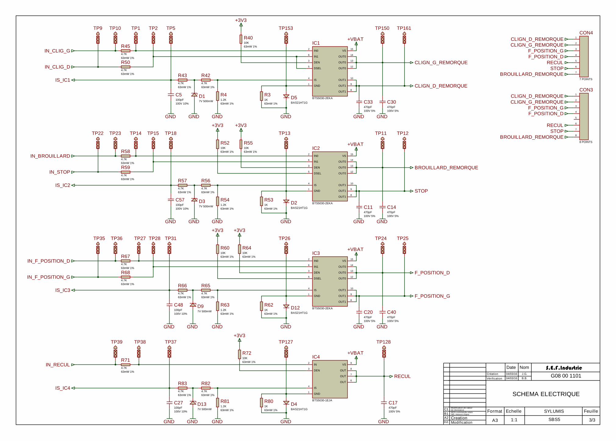
SBS5Ind.
G08 00 1101J.G.
3/3
04/03/16
04/03/16
SCHEMA ELECTRIQUE
S.E.F.IndustrieCréation
Vérification
Date Nom
Format Echelle Feuille
Modification
A2 CreationA3 1:1
SYLUMIS
B.B.
B1MOS commande relaisSEL mesure cligno
C1Modification de valeurde résistance
GND1
IN02
DEN3
IS4
DSEL5
IN16
OUT014
OUT013
OUT012
OUT110
OUT19
OUT18
VS15
IC1
BTS5030-2EKA
C33470pF
100V 5%
C30470pF
100V 5%
GND GND
TP150 TP161
GND
TP153
+VBAT
R31K
63mW 1%
R41.2K
63mW 1%
GND
D5BAS21HT1G
R4010K
63mW 1%
+3V3
R42
4.7K
63mW 1%
D17V 500mW
GND
R43
4.7K
63mW 1%
C5100pF
100V 10%
GND
R45
4.7K
63mW 1%
R50
4.7K
63mW 1%
TP1 TP2 TP5TP9 TP10
1
2
3
4
5
6
7
8
CON3
8 POINTS
1
2
3
4
5
6
7
CON4
7 POINTS
GND1
IN02
DEN3
IS4
DSEL5
IN16
OUT014
OUT013
OUT012
OUT110
OUT19
OUT18
VS15
IC2
BTS5030-2EKA
C11470pF
100V 5%
C14470pF
100V 5%
GND GND
TP11 TP12
GND
TP13
+VBAT
R531K
63mW 1%
R541.2K
63mW 1%
GND
D2BAS21HT1G
R5510K
63mW 1%
+3V3
R56
4.7K
63mW 1%
D37V 500mW
GND
R57
4.7K
63mW 1%
C57100pF
100V 10%
GND
R58
4.7K
63mW 1%
R59
4.7K
63mW 1%
TP14 TP15 TP18TP22 TP23
GND1
IN02
DEN3
IS4
DSEL5
IN16
OUT014
OUT013
OUT012
OUT110
OUT19
OUT18
VS15
IC3
BTS5030-2EKA
C20470pF
100V 5%
C40470pF
100V 5%
GND GND
TP24 TP25
GND
TP26
+VBAT
R621K
63mW 1%
R631.2K
63mW 1%
GND
D12BAS21HT1G
R6410K
63mW 1%
+3V3
R65
4.7K
63mW 1%
D97V 500mW
GND
R66
4.7K
63mW 1%
C48100pF
100V 10%
GND
R67
4.7K
63mW 1%
R68
4.7K
63mW 1%
TP27 TP28 TP31TP35 TP36
GND1
IN2
DEN3
IS4
OUT8
OUT7
OUT6
VS9
IC4
BTS5030-1EJAC17470pF
100V 5%
GND
TP128
+VBAT
GND
TP127
R801K
63mW 1%
D4BAS21HT1G
R811.2K
63mW 1%
GND
R82
4.7K
63mW 1%
D137V 500mW
GND
R83
4.7K
63mW 1%
C27100pF
100V 10%
GND
TP37
R71
4.7K
63mW 1%
TP38TP39
R7210K
63mW 1%
+3V3
IS_IC1
IS_IC2
IS_IC3
IN_CLIG_G
IN_CLIG_D
IN_STOP
IN_BROUILLARD
IN_F_POSITION_D
IN_F_POSITION_G
IN_RECUL
R5210K
63mW 1%
R6010K
63mW 1%
IS_IC4
CLIGN_D_REMORQUE
CLIGN_G_REMORQUE
F_POSITION_G
F_POSITION_D
RECUL
STOP
BROUILLARD_REMORQUE
CLIGN_D_REMORQUE
CLIGN_G_REMORQUE
F_POSITION_G
F_POSITION_D
RECUL
STOP
BROUILLARD_REMORQUE
CLIGN_G_REMORQUE
CLIGN_D_REMORQUE
BROUILLARD_REMORQUE
STOP
F_POSITION_D
F_POSITION_G
RECUL
+3V3
+3V3