ece air handing units installation and operations …€¦ · air handing units installation, ......
TRANSCRIPT

2017 Release
ECE UK LTD Pharaoh House, Arnolde Close, Rochester, Kent. ME2 4QW
Run Around Coil (RAC)
Original Instructions
Air Handing Units
Installation, Operations and Maintenance
Manual
RAC IOM Installation, Operation and Maintenance
for ECE air handling and conditioning units
Checks at Design Stage 2
Table of Contents
Table of Contents ...................................................................................................................................................................... 2
Purpose ................................................................................................................................................................................. 8
RAC Principle and Operation ..................................................................................................................................................... 9
Runaround System .............................................................................................................................................................. 10
Operation ............................................................................................................................................................................ 10
Ancillary Items ..................................................................................................................................................................... 10
Heat Recovery Efficiency ..................................................................................................................................................... 11
Checks at Design Stage ............................................................................................................................................................ 12
Air Inlets and Discharges ..................................................................................................................................................... 13
Acoustics - Vibration ........................................................................................................................................................... 15
Services - Connections......................................................................................................................................................... 15
Commissioning & Fault Finding ........................................................................................................................................... 15
Maintenance Repair and Renewal ...................................................................................................................................... 16
General ................................................................................................................................................................................ 16
GMEB Recommended distance to other components ........................................................................................................ 17
GMEC Recommended distance to other components ........................................................................................................ 18
Air flow measurement device ............................................................................................................................................. 18
Disposal of the product ....................................................................................................................................................... 18
Checks at Order Stage ............................................................................................................................................................. 19
Construction ........................................................................................................................................................................ 20
Finish ................................................................................................................................................................................... 20
Drives ................................................................................................................................................................................... 20
Filters ................................................................................................................................................................................... 20
Inlets and Discharges ........................................................................................................................................................... 20
Volume Control ................................................................................................................................................................... 20
Heating / Cooling ................................................................................................................................................................. 20
Plenums ............................................................................................................................................................................... 20
Inlet / Discharges ................................................................................................................................................................. 20
Vibration Isolators ............................................................................................................................................................... 20
Flexibles ............................................................................................................................................................................... 20
Attenuators ......................................................................................................................................................................... 20
Ancillaries ............................................................................................................................................................................ 20
Protection ............................................................................................................................................................................ 20
Site Costs ............................................................................................................................................................................. 20
Problems ............................................................................................................................................................................. 20
Delivery .................................................................................................................................................................................... 21
Receipt & Unpacking ........................................................................................................................................................... 22
Fan Transport inspection ..................................................................................................................................................... 23
Fan Intermediate storage .................................................................................................................................................... 23
Lifting ................................................................................................................................................................................... 24
Crane - Long lifting straps - 150mm min. width .................................................................................................................. 24
Crane – “H Frame” Short lifting straps - 150mm min. width .............................................................................................. 24
RAC IOM Installation, Operation and Maintenance
for ECE air handling and conditioning units
Checks at Design Stage 3
Forklift ................................................................................................................................................................................. 25
Rollers .................................................................................................................................................................................. 25
Skates .................................................................................................................................................................................. 25
Toe Jacks .............................................................................................................................................................................. 26
Installation ............................................................................................................................................................................... 27
General ................................................................................................................................................................................ 28
Bases and foundations ........................................................................................................................................................ 28
Plug Fans ............................................................................................................................................................................. 30
Fitting the Accessories......................................................................................................................................................... 30
Electrical Connections ......................................................................................................................................................... 30
Lifting of the GMEB fan ....................................................................................................................................................... 31
GMEB Mounting instructions .............................................................................................................................................. 33
Installation of the fan: ......................................................................................................................................................... 33
Built-on frequency converter: ............................................................................................................................................. 33
Fitting the GMEB accessories .............................................................................................................................................. 34
Safety regulations and CE-marking ..................................................................................................................................... 34
GMEB Electrical connections ............................................................................................................................................... 34
Additional grounding of the motor and the built-on frequency converter ........................................................................ 35
GMEC Mounting preparations ............................................................................................................................................ 35
GMEC Mounting Instructions .............................................................................................................................................. 36
GMEC Preparing the Fan Wall ............................................................................................................................................. 36
Mounting of the GMEC fan ................................................................................................................................................. 37
Vertical Mounting – Fan Sizes 025-056 ............................................................................................................................... 37
GMEC Mounting preparation .............................................................................................................................................. 37
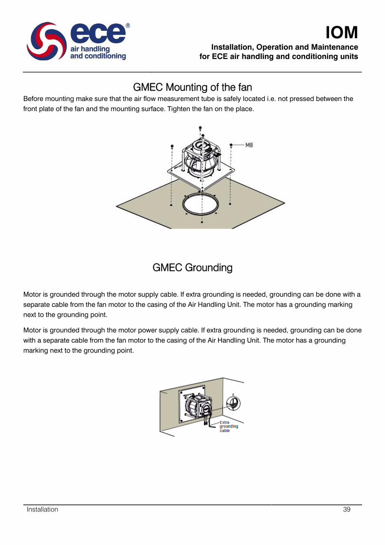
GMEC Mounting of the fan ................................................................................................................................................. 39
GMEC Grounding ................................................................................................................................................................. 39
Fitting the GMEC accessories .............................................................................................................................................. 40
GMEC Electrical Connections .............................................................................................................................................. 40
Installation of the GPEB fan ................................................................................................................................................ 40
Fitting the GPEB accessories ............................................................................................................................................... 40
GPEB Safety regulations ...................................................................................................................................................... 40
GPEB Electrical connections ................................................................................................................................................ 40
SDPV-10 Po Inset Mounting (IP 44) ..................................................................................................................................... 41
SDPV-10 Surface Mounting (IP 54) ...................................................................................................................................... 41
SDPV-10 Isolation and wiring .............................................................................................................................................. 41
SDPV-10 Wiring diagram ..................................................................................................................................................... 42
SDPV-10 Drawings and Dimensions .................................................................................................................................... 43
SDPV-230 Inset Mounting ................................................................................................................................................... 44
SDPV-230 Surface Mounting ............................................................................................................................................... 44
SDPV-230 Wiring Diagram ................................................................................................................................................... 45
SDPV-230 Drawings and Dimensions .................................................................................................................................. 46
EEID Compatibility ............................................................................................................................................................... 47
EEID Inset Mounting ............................................................................................................................................................ 47
EEID Surface Mounting ........................................................................................................................................................ 47

RAC IOM Installation, Operation and Maintenance
for ECE air handling and conditioning units
Checks at Design Stage 4
EEID Change of fuse ............................................................................................................................................................ 47
EEID Motor protection ........................................................................................................................................................ 47
EEID Wiring Diagram ........................................................................................................................................................... 48
EEID Dimensions and Weights ............................................................................................................................................ 49
VSD2H Control Keypad ........................................................................................................................................................ 50
ACC/VSD2H/Hand Held Kit .................................................................................................................................................. 50
ACC/VSD2H/Door Mounting Kit .......................................................................................................................................... 50
Hardware ............................................................................................................................................................................. 51
Isolator Wiring Diagram ...................................................................................................................................................... 52
Isolator Dimensions and weights ........................................................................................................................................ 52
Compatibility ....................................................................................................................................................................... 53
RAC Fan Type & Speed Control ............................................................................................................................................... 54
GMEB Fan Technical Description ........................................................................................................................................ 55
Design .................................................................................................................................................................................. 55
GMEB Operating conditions ................................................................................................................................................ 56
GMEB Motors ...................................................................................................................................................................... 56
GMEB Frequency Converters .............................................................................................................................................. 56
GMEB Fan impeller .............................................................................................................................................................. 56
GMEB Fan Inlet .................................................................................................................................................................... 56
GMEB Motor base with base frame .................................................................................................................................... 57
GMEB Hub ........................................................................................................................................................................... 57
GMEB Air flow sensor .......................................................................................................................................................... 57
GMEB Directive for machinery ............................................................................................................................................ 57
GMEC Technical Description ............................................................................................................................................... 58
GMEC Design ....................................................................................................................................................................... 58
GMEC Operating Conditions ............................................................................................................................................... 58
GMEC Motors ...................................................................................................................................................................... 59
GMEC Important information ............................................................................................................................................. 59
SDPV-10 Potentiometer ...................................................................................................................................................... 60
Features: .............................................................................................................................................................................. 60
SDPV-10 Description ........................................................................................................................................................... 61
SDPV-10 Range .................................................................................................................................................................... 61
SDPV-10 Technical Data ...................................................................................................................................................... 61
SDPV – 10 Wiring Diagram .................................................................................................................................................. 62
SDPV-230 – Room Potentiometer ....................................................................................................................................... 63
SDPV-230 Features .............................................................................................................................................................. 63
SDPV-230 Description ......................................................................................................................................................... 63
SDPV-230 Range .................................................................................................................................................................. 63
SDPV-230 Technical Data .................................................................................................................................................... 64
SDPV – 230 Wiring Diagram ................................................................................................................................................ 65
EEID – Electronic Single Phase ............................................................................................................................................. 66
EEID Features ...................................................................................................................................................................... 66
EEID Description .................................................................................................................................................................. 66
EEID Range and Motor Protection ...................................................................................................................................... 67
RAC IOM Installation, Operation and Maintenance
for ECE air handling and conditioning units
Checks at Design Stage 5
EEID Wiring Diagram ........................................................................................................................................................... 67
Trend - VSD2H Variable Isolator Speed Drives .................................................................................................................... 68
VSD2H Variable Isolator Speed Description ........................................................................................................................ 68
VSD2H Variable Isolator Speed Features ............................................................................................................................ 68
Physical (dimensions in mm) ............................................................................................................................................... 69
Physical (continued) ............................................................................................................................................................ 69
Functionality ........................................................................................................................................................................ 70
Hardware ............................................................................................................................................................................. 71
DIP Switch ............................................................................................................................................................................ 77
Quick setup .......................................................................................................................................................................... 78
Monitoring........................................................................................................................................................................... 78
Parameters .......................................................................................................................................................................... 78
Diagnostics .......................................................................................................................................................................... 78
I/O and hardware ................................................................................................................................................................ 78
User settings ........................................................................................................................................................................ 78
Favourites ............................................................................................................................................................................ 78
Digital Input Isolation .......................................................................................................................................................... 78
Ethernet Connection ........................................................................................................................................................... 79
RS485 Connection ............................................................................................................................................................... 79
Real Time Clock ................................................................................................................................................................... 79
Integrated RFI-filter ............................................................................................................................................................. 80
Integrated DC Choke ........................................................................................................................................................... 80
Integrated Stress Removal .................................................................................................................................................. 80
External Keypad ................................................................................................................................................................... 80
ACC/VSD2H/Hand Held Kit .................................................................................................................................................. 81
ACC/VSD2H/Door Mounting Kit .......................................................................................................................................... 81
Hardware ............................................................................................................................................................................. 82
Quick Setup ......................................................................................................................................................................... 84
Uninterruptible Operation and Energy Saving .................................................................................................................... 84
VFD and Motor Control ....................................................................................................................................................... 85
Advanced HVAC Control ...................................................................................................................................................... 85
Software .............................................................................................................................................................................. 86
SISO – Safety Isolators/Switch-disconnectors ..................................................................................................................... 87
Switches & Sensors ............................................................................................................................................................. 87
Features ............................................................................................................................................................................... 87
Description .......................................................................................................................................................................... 87
Range ................................................................................................................................................................................... 88
AHU Commissioning ................................................................................................................................................................ 89
Runaround Coils .................................................................................................................................................................. 90
Typical Piping Arrangement with Air Handling Units Separated ......................................................................................... 90
Typical Piping Arrangement for Integral Runaround Set .................................................................................................... 91
Single Pressurisation Pump, Single Circulating Pump ......................................................................................................... 92
Single Pressurisation Pump, Twin Circulating Pumps with Flow Switch and Auto Changeover ......................................... 93
Wiring Schematic................................................................................................................................................................. 94

RAC IOM Installation, Operation and Maintenance
for ECE air handling and conditioning units
Checks at Design Stage 6
Plug / SISW / DIDW Fans - Motors – Drives ........................................................................................................................ 95
Belt Drives ........................................................................................................................................................................... 95
Anti-Vibration Mountings.................................................................................................................................................... 97
Checking Label Positioning .................................................................................................................................................. 97
Servicing Filters ................................................................................................................................................................... 98
Shut off VCD’s - HRD’s ....................................................................................................................................................... 100
Coils ................................................................................................................................................................................... 100
Coil Connections ................................................................................................................................................................ 101
Setting Water Flow through Coils ..................................................................................................................................... 102
Coil Condensate Drains ..................................................................................................................................................... 103
Blow through units with positive pressure at trap ............................................................................................................ 104
Coil Condensate Faults ...................................................................................................................................................... 105
Blow Through .................................................................................................................................................................... 106
Draw through coils with condensate pump ...................................................................................................................... 107
Chilled Water Cooling and LP Hot Water Heating Coils .................................................................................................... 108
Bypass Circuit .................................................................................................................................................................... 108
Mixing circuit using three-way mixing valves. ................................................................................................................... 108
Chilled Water Cooling Coils ............................................................................................................................................... 109
Hot Water Heating Coils .................................................................................................................................................... 110
Steam Coils ........................................................................................................................................................................ 111
Electric Heater Batteries ................................................................................................................................................... 113
Gas Fired Heaters .............................................................................................................................................................. 114
Electronic Steam Humidifiers ............................................................................................................................................ 116
GMEC Commissioning ....................................................................................................................................................... 118
Safety checking .................................................................................................................................................................. 118
Test run ............................................................................................................................................................................. 118
GPEB Commissioning ......................................................................................................................................................... 118
Test Run ............................................................................................................................................................................. 118
GMEB Commissioning ....................................................................................................................................................... 119
Safety Checking ................................................................................................................................................................. 119
Test Run ............................................................................................................................................................................. 119
Maintenance.......................................................................................................................................................................... 120
Plug Fan Air flow measurement device ............................................................................................................................. 121
Disposal of the product ..................................................................................................................................................... 121
Before Maintenance .......................................................................................................................................................... 121
Inspection .......................................................................................................................................................................... 121
Checking the motor bearings ............................................................................................................................................ 121
Impeller ............................................................................................................................................................................. 121
Replacing the motor and impeller ..................................................................................................................................... 122
Final inspection ................................................................................................................................................................. 123
SDPV-10 Maintenance ....................................................................................................................................................... 124
SDPV-230 Maintenance ..................................................................................................................................................... 124
Maintenance Schedule ...................................................................................................................................................... 125
SISW / DIDW - Fan Bearings .............................................................................................................................................. 127

RAC IOM Installation, Operation and Maintenance
for ECE air handling and conditioning units
Checks at Design Stage 7
Spider Arm Bearing ........................................................................................................................................................... 127
Plummer Block Bearing ..................................................................................................................................................... 128
Replacing the filters (for HTM specification units) ............................................................................................................ 129
Motor Bearings .................................................................................................................................................................. 131
Motors without Grease Points .......................................................................................................................................... 131
Motor Overheating............................................................................................................................................................ 131
Washable Filters ................................................................................................................................................................ 131
Autoroll Filters ................................................................................................................................................................... 131
Activated Carbon (Constantly Monitored) ........................................................................................................................ 131
Activated Carbon (disposable non-monitored) ................................................................................................................. 131
Electric Heater Batteries ................................................................................................................................................... 132
Dampers - Motors ............................................................................................................................................................. 132
Coils - General ................................................................................................................................................................... 132
DX Cooling Coils ................................................................................................................................................................. 132
Fault Finding .......................................................................................................................................................................... 133
Centrifugal Fans ................................................................................................................................................................. 134
Electric Heaters ................................................................................................................................................................. 135
Cooling Coils ...................................................................................................................................................................... 135
Heating Coils ...................................................................................................................................................................... 137
Refrigeration ..................................................................................................................................................................... 137
Fan Drive Belts ................................................................................................................................................................... 138
RAC IOM Installation, Operation and Maintenance
for ECE air handling and conditioning units
Checks at Design Stage 8
Purpose
This manual contains advice for installers and users.
General information about the range, construction and selection of ECE air handling/conditioning equipment can be
obtained from our website, various sales publications, or by telephone.
Certified individual unit data concerning dimensions, weights, component specification and performance, is issued with
the order acknowledgement for each unit.
Due to our policy of continuous improvement the information contained within this Manual may be altered from time to
time without prior notice.
RAC IOM Installation, Operation and Maintenance
for ECE air handling and conditioning units
Checks at Design Stage 9
RAC Principle and Operation

RAC IOM Installation, Operation and Maintenance
for ECE air handling and conditioning units
Checks at Design Stage 10
Runaround System
Operation
It is common for the supply and extract air handlers containing the run around coil system to be joined together, either in
a side-by-side or a stacked configuration. However if required the units can be separated and up to 15 metres apart.
The use of this system is generally limited to applications where the air streams are separated and no other type of device
can be utilised since the heat recovery efficiency is lower than other forms of air-to-air heat recovery. Seasonal efficiencies
of this system can be very low, due to the extra electrical energy used by the pumped fluid circuit.
A run-around coil system comprises two or more multi-row finned tube coils connected to each other by a pumped
pipework circuit. The pipework is charged with a heat exchange fluid, water, which picks up heat from the exhaust air coil
and gives up heat to the supply air coil before returning again. Thus heat from the exhaust air stream is transferred
through the pipework coil to the circulating fluid, and then from the fluid through the pipework coil to the supply air
stream.
From this process the specific heat output capacity depends on the temperature difference between the two air streams.
Hence the coil is suitable for heat as well as cool recovery, i.e. for winter and summer operation.
The fluid circuit, as well as containing the circulating pump, will also contain an expansion vessel, to accommodate
changes in fluid pressure; a fill device, to ensure the system remains charged; controls to bypass and shut down the
system when not required, and various other safety devices and ancillaries.
Pipework runs should be kept as short as possible and should be sized for low velocities to keep frictional losses to a
minimum, and hence reduce pump energy consumption. It is possible however to recover some of this energy in the form
of heat given off by the motor if a glandless pump is used, where a water jacket surrounds the motor stator, thus water
passing through the pump will pick up some of its heat.
The pumped fluid will have to be protected from freezing in certain climates, and as such is normally treated with a glycol
based anti-freeze. This also reduces the specific heat capacity of the fluid and increases the viscosity, increasing pump
power consumption, further reducing the seasonal efficiency of the device. For example, a 20% glycol mixture will provide
protection down to −10 °C (14 °F), but will increase system resistance by 15%.
For the finned tube coil design, there is a performance maximum corresponding to an eight- or ten-row coil, above this
the fan and pump motor energy consumption increases substantially and seasonal efficiency starts to drop off. The main
cause of increased energy consumption lies with the fan, for the same face velocity, fewer coil rows will decrease air
pressure drop and increase water pressure drop but the total energy consumption will usually be less than that for a
greater number of coil rows with higher air pressure drops and lower water pressure drops.
Ancillary Items
Air filtration is always present in order to provide clean dust-free air to the building occupants.
Direct heating, placed directly in the air stream, are direct heat exchangers and include those for gas-fired fuel-burning
heaters or electric air heater batteries (EAHB).
Indirect Heating and Cooling coils use hot water or steam for heating, and chilled water for cooling. Heat pumps can be
used as well. (Prime energy for heating and cooling is provided by central plant).
Humidification is often necessary in colder climates where continuous heating will make the air drier, resulting in
uncomfortable air quality and increased static electricity. Various types of humidification may be used as part of our air
handler and include evaporative, vaporizer, spray mist and wetted medium.

RAC IOM Installation, Operation and Maintenance
for ECE air handling and conditioning units
Checks at Design Stage 11
If dehumidification is required, then the cooling coil is employed to over-cool so that the dew point is reached and
condensation occurs. A heater coil placed after the cooling coil re-heats the air to the desired supply temperature and
humidity level. This is often used for chilled beam applications.
Heat Recovery Efficiency
The correct efficiency is a subjective decision and depends on the economic calculation and written guidelines, i.e.
Ecodesign Commission Regulation (EU) No 1253/2014, on operating data such as energy prices, useful life, running
times, temperatures, maintenance costs, and interest rates. With regard to (EU) No 1253/2014, profitability and
environmental protection the heat recovery efficiency should be no less than 63%
Dependent on the right conditions heat recovery efficiencies can reach 70%
Air handling units incorporating run around coils are important elements in saving energy in Hotels, Retail, Corporate,
High End Housing, Sports & Leisure, Education, Offices, Industrial, Data Centre, Health, and ATEX.
This investment passes off in several ways:
Lower energy consumption
Lower investment for heat generation and distribution
Less damage to the environment
RAC IOM Installation, Operation and Maintenance
for ECE air handling and conditioning units
Checks at Design Stage 12
Checks at Design Stage
RAC IOM Installation, Operation and Maintenance
for ECE air handling and conditioning units
Checks at Design Stage 13
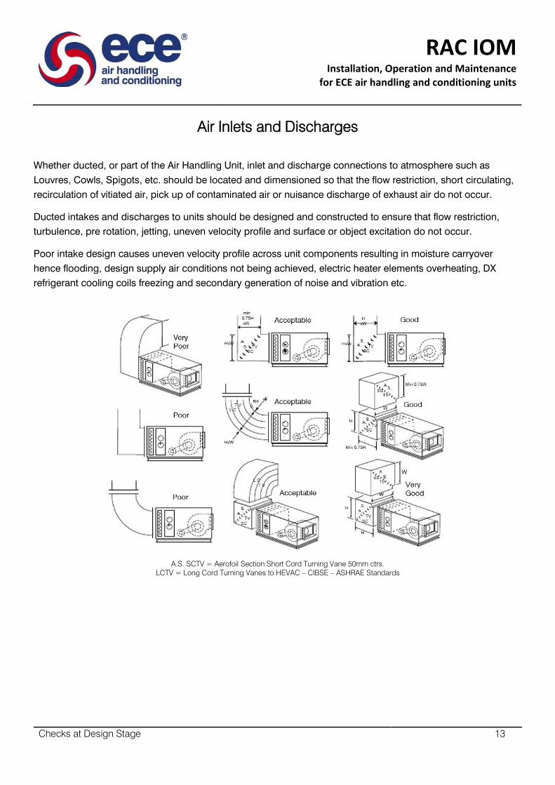
Air Inlets and Discharges
Whether ducted, or part of the Air Handling Unit, inlet and discharge connections to atmosphere such as
Louvres, Cowls, Spigots, etc. should be located and dimensioned so that the flow restriction, short circulating,
recirculation of vitiated air, pick up of contaminated air or nuisance discharge of exhaust air do not occur.
Ducted intakes and discharges to units should be designed and constructed to ensure that flow restriction,
turbulence, pre rotation, jetting, uneven velocity profile and surface or object excitation do not occur.
Poor intake design causes uneven velocity profile across unit components resulting in moisture carryover
hence flooding, design supply air conditions not being achieved, electric heater elements overheating, DX
refrigerant cooling coils freezing and secondary generation of noise and vibration etc.
A.S. SCTV = Aerofoil Section Short Cord Turning Vane 50mm ctrs.
LCTV = Long Cord Turning Vanes to HEVAC – CIBSE – ASHRAE Standards

RAC IOM Installation, Operation and Maintenance
for ECE air handling and conditioning units
Checks at Design Stage 14
Poor discharge design causes reduction in fan pressure and volume, also turbulence generating secondary
noise and vibration, which may reduce impeller, bearing, isolator and flexible connection life. Design supply
conditions may also be achieved. Electric elements may overheat. DX coils may freeze.
A.S. SCTV = Aerofoil Section Short Cord Turning Vane 50mm ctrs.
D = Fan inlet eye diameter
LCTV = Long Cord Turning Vanes to HEVAC – CIBSE – ASHRAE Standards
RAC IOM Installation, Operation and Maintenance
for ECE air handling and conditioning units
Checks at Design Stage 15
Acoustics - Vibration
Ensure space exists for incorporating attenuation of the noise to atmosphere from outside air inlet and exhaust
air discharge and on room side supply and extract ducts.
Consider noise from casing radiation, flanking and breakout.
Consider primary and secondary vibration isolation including service connections.
Services - Connections
Ensure space with clearance exists for access to, routing of, connection to and expansion and contraction of
water, steam, refrigerant, gas oil supplies and line fittings. Combustion air supply, flue gas exhaust. Venting of
air, isolating and draining of plant, trapping and returning steam, condensate, trapping and draining of
condense from cooling coils, humidifiers and heat recovery devices to open tundish, blowing down waste to
open tundish, pumping down and storing of refrigerant, power – control wiring, and components.
Commissioning & Fault Finding
Ensure plant is designed to allow installation of and access to calibration and adjustment of measuring and
modulating devices for:
Air flow direction and rate
Medium flow direction and rate
Resistance to airflow
Resistance to medium flow
Air on and off dry bulb, wet bulb and humidity
Medium on and off pressure and temperature
Ensure space exists in and around the plant for access to, inspection of, measuring of and work on items
including:
Belt tensioning of external motors
Jacking and levelling of steel spring vibration isolators
Clear sight of identifying labels measuring and recording devices
VCD blades, links and actuators, humidifier generators, sparge pipes, coil and eliminator surfaces and
drain pans, electric heaters, fan and drives
Fan speed and direction of rotation
Motor current, resistance, continuity
Motor nameplate
Terminal wiring diagrams
Wiring
IOM
Installation, Operation and Maintenance
for ECE air handling and conditioning units
Checks at Design Stage 16
Maintenance Repair and Renewal
For units with one piece coils ensure space exists of at least one unit width plus 150mm on the withdrawal side
of each plant item. For units with split coils ensure at least half the width of the unit or 700mm whichever is
greater.
Adjacent units can share the common space between them for access and withdrawal.
Ensure room exists for safe working platforms where units are mounted at a high level.
Ensure provision exists for steps, ladders and mezzanine etc. Where units are over 1750mm high or mounted
on platforms which elevate the unit height and make access difficult.
General
Any or all of the following and their effect on the plant should be considered and the appropriate action taken:
Conditions within surrounding areas
External temperature and humidity
Direct solar radiation
Wind speed and direction
Driven rain
Driven snow
Driven sand
Sea spray, mist, fog, moisture in suspension
Saline atmosphere
Icing
Unit surface temperatures and surrounding air dew point
Gases which form acids in solution in water, such as SO²
Flammability
Explosion risk
Toxicity
Bacteria
Fungi
Algae
IOM
Installation, Operation and Maintenance
for ECE air handling and conditioning units
Checks at Design Stage 17
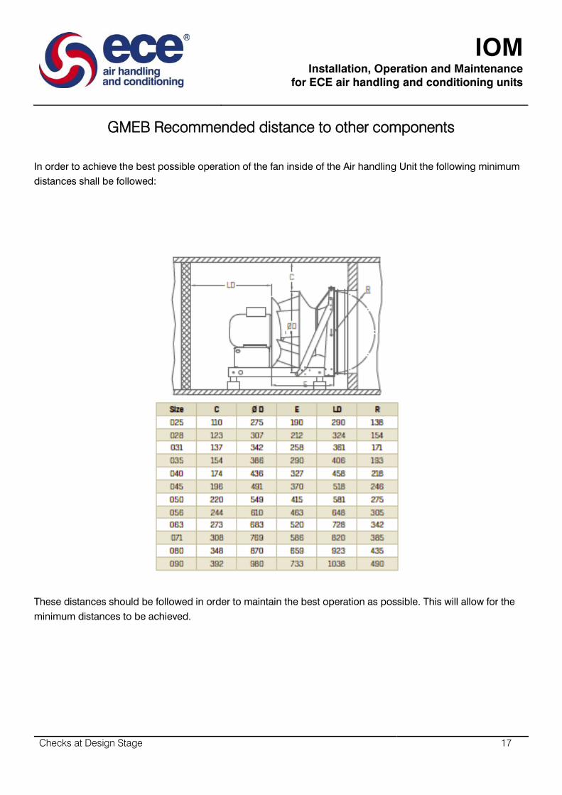
GMEB Recommended distance to other components
In order to achieve the best possible operation of the fan inside of the Air handling Unit the following minimum
distances shall be followed:
These distances should be followed in order to maintain the best operation as possible. This will allow for the
minimum distances to be achieved.

IOM
Installation, Operation and Maintenance
for ECE air handling and conditioning units
Checks at Design Stage 18
GMEC Recommended distance to other components
To achieve the best possible operation of the fan inside of the Air Handling Unit the following minimum
distances shall be followed:
Air flow measurement device
The airflow sensor is used for measuring the airflow of the plug fans. The method is based on differential
pressure. The pressure is measured at a specific point in the inlet cone and the reference pressure is measured
upstream of the inlet cone. The air flow sensor is supplied factory mounted in the inlet cone.
Disposal of the product
Used product shall be disposed or recycled according to the local laws and regulations.

IOM
Installation, Operation and Maintenance
for ECE air handling and conditioning units
Checks at Order Stage 19
Checks at Order Stage
IOM
Installation, Operation and Maintenance
for ECE air handling and conditioning units
Checks at Order Stage 20
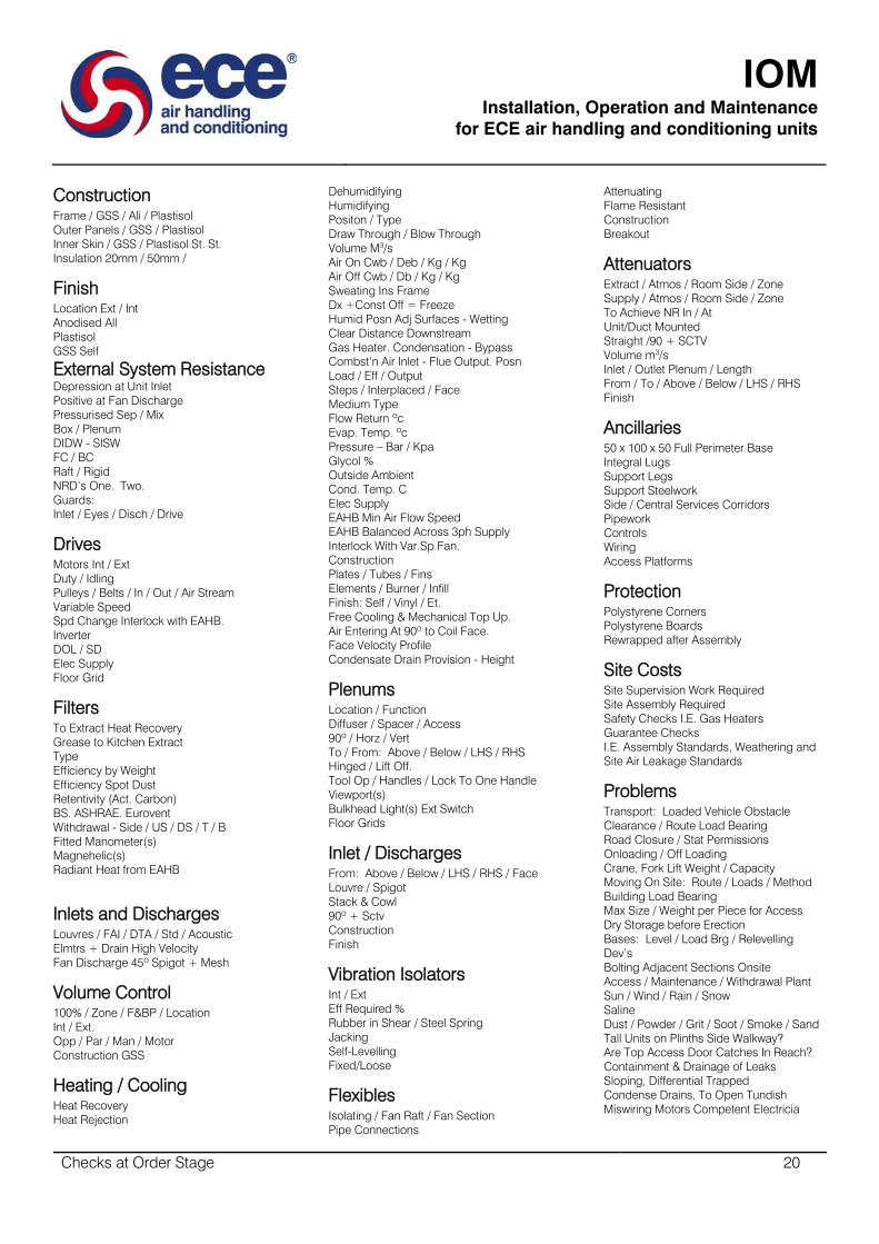
Construction
Frame / GSS / Ali / Plastisol
Outer Panels / GSS / Plastisol
Inner Skin / GSS / Plastisol St. St.
Insulation 20mm / 50mm /
Finish
Location Ext / Int
Anodised All
Plastisol
GSS Self
External System Resistance
Depression at Unit Inlet
Positive at Fan Discharge
Pressurised Sep / Mix
Box / Plenum
DIDW - SISW
FC / BC
Raft / Rigid
NRD’s One. Two.
Guards:
Inlet / Eyes / Disch / Drive
Drives
Motors Int / Ext
Duty / Idling
Pulleys / Belts / In / Out / Air Stream
Variable Speed
Spd Change Interlock with EAHB.
Inverter
DOL / SD
Elec Supply
Floor Grid
Filters
To Extract Heat Recovery
Grease to Kitchen Extract
Type
Efficiency by Weight
Efficiency Spot Dust
Retentivity (Act. Carbon)
BS. ASHRAE. Eurovent
Withdrawal - Side / US / DS / T / B
Fitted Manometer(s)
Magnehelic(s)
Radiant Heat from EAHB
Inlets and Discharges
Louvres / FAI / DTA / Std / Acoustic
Elmtrs + Drain High Velocity
Fan Discharge 45º Spigot + Mesh
Volume Control
100% / Zone / F&BP / Location
Int / Ext.
Opp / Par / Man / Motor
Construction GSS
Heating / Cooling
Heat Recovery
Heat Rejection
Dehumidifying
Humidifying
Positon / Type
Draw Through / Blow Through
Volume M3/s
Air On Cwb / Deb / Kg / Kg
Air Off Cwb / Db / Kg / Kg
Sweating Ins Frame
Dx +Const Off = Freeze
Humid Posn Adj Surfaces - Wetting
Clear Distance Downstream
Gas Heater. Condensation - Bypass
Combst’n Air Inlet - Flue Output. Posn
Load / Eff / Output
Steps / Interplaced / Face
Medium Type
Flow Return ºc
Evap. Temp. ºc
Pressure – Bar / Kpa
Glycol %
Outside Ambient
Cond. Temp. C
Elec Supply
EAHB Min Air Flow Speed
EAHB Balanced Across 3ph Supply
Interlock With Var.Sp.Fan.
Construction
Plates / Tubes / Fins
Elements / Burner / Infill
Finish: Self / Vinyl / Et.
Free Cooling & Mechanical Top Up.
Air Entering At 90º to Coil Face.
Face Velocity Profile
Condensate Drain Provision - Height
Plenums
Location / Function
Diffuser / Spacer / Access
90º / Horz / Vert
To / From: Above / Below / LHS / RHS
Hinged / Lift Off.
Tool Op / Handles / Lock To One Handle
Viewport(s)
Bulkhead Light(s) Ext Switch
Floor Grids
Inlet / Discharges
From: Above / Below / LHS / RHS / Face
Louvre / Spigot
Stack & Cowl
90º + Sctv
Construction
Finish
Vibration Isolators
Int / Ext
Eff Required %
Rubber in Shear / Steel Spring
Jacking
Self-Levelling
Fixed/Loose
Flexibles
Isolating / Fan Raft / Fan Section
Pipe Connections
Attenuating
Flame Resistant
Construction
Breakout
Attenuators
Extract / Atmos / Room Side / Zone
Supply / Atmos / Room Side / Zone
To Achieve NR In / At
Unit/Duct Mounted
Straight /90 + SCTV
Volume m3/s
Inlet / Outlet Plenum / Length
From / To / Above / Below / LHS / RHS
Finish
Ancillaries
50 x 100 x 50 Full Perimeter Base
Integral Lugs
Support Legs
Support Steelwork
Side / Central Services Corridors
Pipework
Controls
Wiring
Access Platforms
Protection
Polystyrene Corners
Polystyrene Boards
Rewrapped after Assembly
Site Costs
Site Supervision Work Required
Site Assembly Required
Safety Checks I.E. Gas Heaters
Guarantee Checks
I.E. Assembly Standards, Weathering and
Site Air Leakage Standards
Problems
Transport: Loaded Vehicle Obstacle
Clearance / Route Load Bearing
Road Closure / Stat Permissions
Onloading / Off Loading
Crane, Fork Lift Weight / Capacity
Moving On Site: Route / Loads / Method
Building Load Bearing
Max Size / Weight per Piece for Access
Dry Storage before Erection
Bases: Level / Load Brg / Relevelling
Dev’s
Bolting Adjacent Sections Onsite
Access / Maintenance / Withdrawal Plant
Sun / Wind / Rain / Snow
Saline
Dust / Powder / Grit / Soot / Smoke / Sand
Tall Units on Plinths Side Walkway?
Are Top Access Door Catches In Reach?
Containment & Drainage of Leaks
Sloping, Differential Trapped
Condense Drains, To Open Tundish
Miswiring Motors Competent Electricia

IOM
Installation, Operation and Maintenance
for ECE air handling and conditioning units
Delivery 21
Delivery
IOM
Installation, Operation and Maintenance
for ECE air handling and conditioning units
Delivery 22
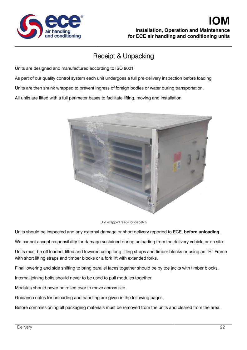
Receipt & Unpacking
Units are designed and manufactured according to ISO 9001
As part of our quality control system each unit undergoes a full pre-delivery inspection before loading.
Units are then shrink wrapped to prevent ingress of foreign bodies or water during transportation.
All units are fitted with a full perimeter bases to facilitate lifting, moving and installation.
Unit wrapped ready for dispatch
Units should be inspected and any external damage or short delivery reported to ECE, before unloading.
We cannot accept responsibility for damage sustained during unloading from the delivery vehicle or on site.
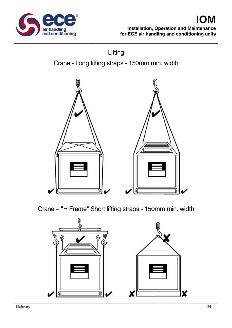
Units must be off loaded, lifted and lowered using long lifting straps and timber blocks or using an “H” Frame
with short lifting straps and timber blocks or a fork lift with extended forks.
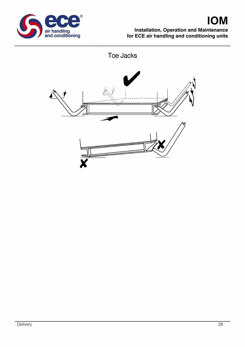
Final lowering and side shifting to bring parallel faces together should be by toe jacks with timber blocks.
Internal joining bolts should never to be used to pull modules together.
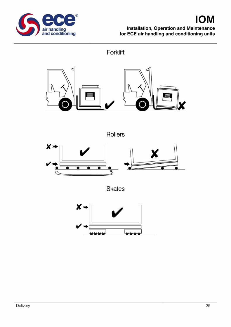
Modules should never be rolled over to move across site.
Guidance notes for unloading and handling are given in the following pages.
Before commissioning all packaging materials must be removed from the units and cleared from the area.
IOM
Installation, Operation and Maintenance
for ECE air handling and conditioning units
Delivery 23
Fan Transport inspection
Check the fan immediately after you receive it and make sure that it has not been damaged during transport. If
you discover any damage, get in touch with the ECE aftersales without delay. Briefly rotate the fan impeller to
see that it rotates easily. Check the information on the fan rating plate.
Faulty conditions in transporting may result in serious damage on the product.
Fan Intermediate storage
If the fan is to be switched off in between uses, the following needs to be taken in to account:
- The storage environment must be dry, dust-free and not have a high level of humidity (<70%)
- Storage temperature must be in between -25°C and + 40°C
IOM
Installation, Operation and Maintenance
for ECE air handling and conditioning units
Delivery 24
Lifting
Crane - Long lifting straps - 150mm min. width
Crane – “H Frame” Short lifting straps - 150mm min. width
IOM
Installation, Operation and Maintenance
for ECE air handling and conditioning units
Delivery 25
Forklift
Rollers
Skates
IOM
Installation, Operation and Maintenance
for ECE air handling and conditioning units
Delivery 26
Toe Jacks

IOM
Installation, Operation and Maintenance
for ECE air handling and conditioning units
Installation 27
Installation
IOM
Installation, Operation and Maintenance
for ECE air handling and conditioning units
Installation 28
General
Electrical wiring and controls, water, steam, gas and refrigerant piping, line fittings and controls should be
installed in accordance with appropriate governing institute standard practice (I.E.E. C.I.B.S.E. etc.) and
together with the electricity supply, water supply and drains should conform to the appropriate authority and all
statutory regulations.
Units with drains should be mounted at a level which allows installation of cleanable drain taps at each
connecting point then installation of drain pipe work falling to an open tundish.
Space should exist for the application of sealant - jointing rubbers. Tightening of internal fixings. Internal
installation, attachment or insertion of isolating, indicating, recoding, modulating, activating, devices, also
making and tightening of fixings at connections to air Inlet and discharge ducts.
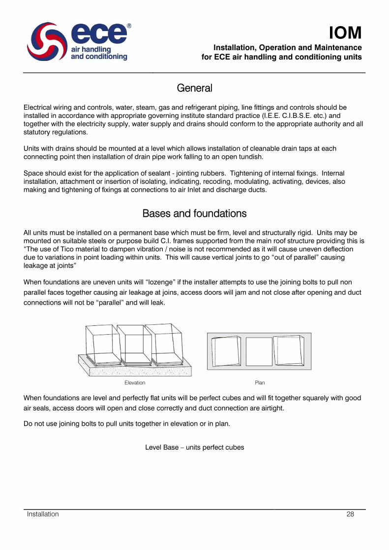
Bases and foundations
All units must be installed on a permanent base which must be firm, level and structurally rigid. Units may be
mounted on suitable steels or purpose build C.I. frames supported from the main roof structure providing this is
“The use of Tico material to dampen vibration / noise is not recommended as it will cause uneven deflection
due to variations in point loading within units. This will cause vertical joints to go “out of parallel” causing
leakage at joints”
When foundations are uneven units will “lozenge” if the installer attempts to use the joining bolts to pull non
parallel faces together causing air leakage at joins, access doors will jam and not close after opening and duct
connections will not be “parallel” and will leak.
Elevation Plan
When foundations are level and perfectly flat units will be perfect cubes and will fit together squarely with good
air seals, access doors will open and close correctly and duct connection are airtight.
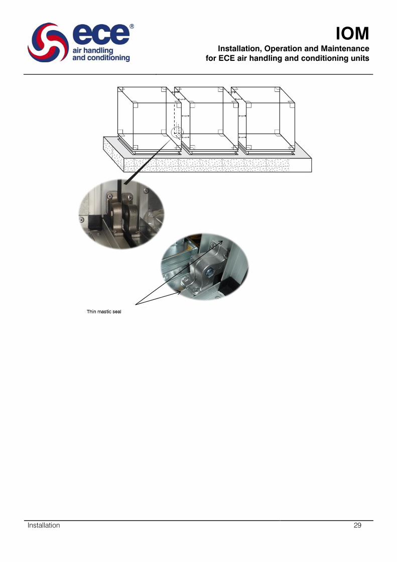
Do not use joining bolts to pull units together in elevation or in plan.
Level Base – units perfect cubes
IOM
Installation, Operation and Maintenance
for ECE air handling and conditioning units
Installation 29

IOM
Installation, Operation and Maintenance
for ECE air handling and conditioning units
Installation 30
Plug Fans
The fan is secured to a base by bolts in mounting holes across anti-vibration
mountings. The base must be level and stable. The fan must only be mounted
in a horizontal plane. Either the fan or the base is mounted on anti-vibration
mountings.
Fitting the Accessories
The fan should normally be connected to the air handling unit by means of
flexible connection or other type of gasket to eliminate vibration transfer from fan to AHU casing. Providing
necessary grounding for the accessories is within the constructor’s field of responsibility. Inlet protective screen
can be fitted directly to the front frame or outside AHU to the inlet opening.
Electrical Connections
All electrical connections must be wired by authorised personnel only. The necessary electrical and safety
precautions must be taken into account. If the motor is operated across a frequency converter, the connections
must be made according to the instructions of the frequency converter manufacturer. The motor must be grounded.
IOM
Installation, Operation and Maintenance
for ECE air handling and conditioning units
Installation 31
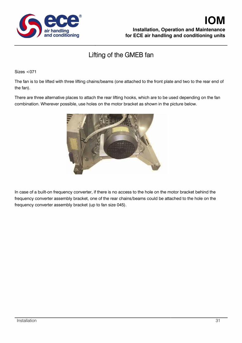
Lifting of the GMEB fan
Sizes <071
The fan is to be lifted with three lifting chains/beams (one attached to the front plate and two to the rear end of
the fan).
There are three alternative places to attach the rear lifting hooks, which are to be used depending on the fan
combination. Wherever possible, use holes on the motor bracket as shown in the picture below.
In case of a built-on frequency converter, if there is no access to the hole on the motor bracket behind the
frequency converter assembly bracket, one of the rear chains/beams could be attached to the hole on the
frequency converter assembly bracket (up to fan size 045).
IOM
Installation, Operation and Maintenance
for ECE air handling and conditioning units
Installation 32
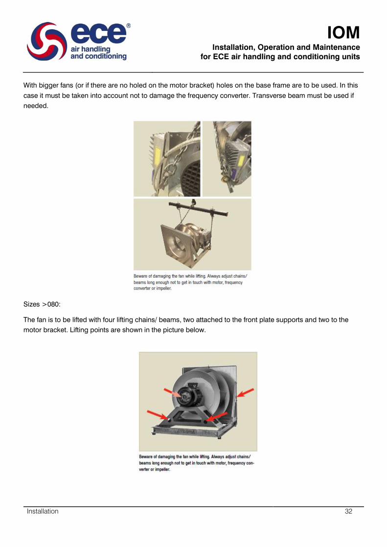
With bigger fans (or if there are no holed on the motor bracket) holes on the base frame are to be used. In this
case it must be taken into account not to damage the frequency converter. Transverse beam must be used if
needed.
Sizes >080:
The fan is to be lifted with four lifting chains/ beams, two attached to the front plate supports and two to the
motor bracket. Lifting points are shown in the picture below.
IOM
Installation, Operation and Maintenance
for ECE air handling and conditioning units
Installation 33
GMEB Mounting instructions
Installation of the fan:
The fan is to be installed to a base frame using anti-vibration mountings. Alternatively the base could be
mounted on anti-vibration mountings.
The base must be level and stable. The fan must only be mounted in a horizontal plane.
Built-on frequency converter:
If needed, the frequency converter can be removed to the other side of the fan with the following instructions.
Otherwise please use the cable tie (delivered with the fan) to attach the motor cable to the motor bracket and
mounting plate.
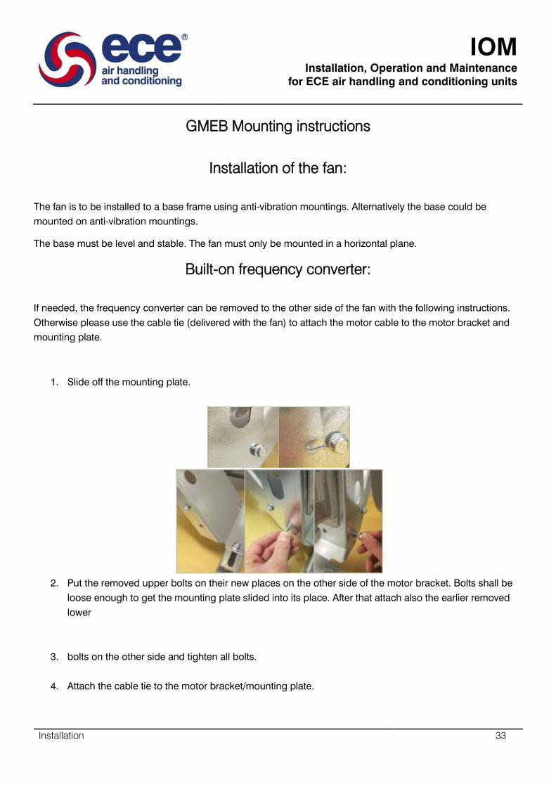
1. Slide off the mounting plate.
2. Put the removed upper bolts on their new places on the other side of the motor bracket. Bolts shall be
loose enough to get the mounting plate slided into its place. After that attach also the earlier removed
lower
3. bolts on the other side and tighten all bolts.
4. Attach the cable tie to the motor bracket/mounting plate.

IOM
Installation, Operation and Maintenance
for ECE air handling and conditioning units
Installation 34
5. In case of fan size 080 frequency converter also assembled with mounting plate: Remove the frequency
converter first to better access the mounting plate fixing bolts. Loosen the upper bolts and remove the
lower bolts to detach the mounting plate. Reassemble in reverse order.
Fitting the GMEB accessories
The fan should normally be connected to the air handling unit by means of flexible connection or other type of a
gasket to eliminate vibration transfer from fan to the AHU casing.
Providing necessary grounding for the accessories is within the constructor’s field of responsibility.
Inlet protective screen can be fitted directly to the front frame or outside AHU to the inlet opening.
Safety regulations and CE-marking
The GMPM and GMEB fan is CE-marked as a partly completed machinery and must not be put into service until
the final machinery and must not be put into service until the final machinery and must not be put into service
until the final machinery into which it is to be incorporated has been declared in conformity with provisions of
the machinery Directive 2006/42/EC. The fan is ErP compliant. Other compliant directives are shown in the
Declaration of Conformity.
GMEB Electrical connections
All electrical connections must be wired by authorised personnel only. The necessary electrical and safety
precautions must be taken into account. If the motor is operated across a frequency converter, the connections
must be made according to the instructions of the frequency converter manufacturer. The motor must be
grounded.
IOM
Installation, Operation and Maintenance
for ECE air handling and conditioning units
Installation 35
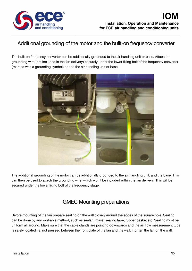
Additional grounding of the motor and the built-on frequency converter
The built-on frequency converter can be additionally grounded to the air handling unit or base. Attach the
grounding wire (not included in the fan delivery) securely under the lower fixing bolt of the frequency converter
(marked with a grounding symbol) and to the air handling unit or base.
The additional grounding of the motor can be additionally grounded to the air handling unit, and the base. This
can then be used to attach the grounding wire, which won’t be included within the fan delivery. This will be
secured under the lower fixing bolt of the frequency stage.
GMEC Mounting preparations
Before mounting of the fan prepare sealing on the wall closely around the edges of the square hole. Sealing
can be done by any workable method, such as sealant mass, sealing tape, rubber gasket etc. Sealing must be
uniform all around. Make sure that the cable glands are pointing downwards and the air flow measurement tube
is safely located i.e. not pressed between the front plate of the fan and the wall. Tighten the fan on the wall.

IOM
Installation, Operation and Maintenance
for ECE air handling and conditioning units
Installation 36
GMEC Mounting Instructions
Horizontal wall mounting inside the fan casing – Fan sizes 025-056
GMEC Preparing the Fan Wall
First make sure that the wall is rigid enough. There must be a circular hole and mounting screws symmetrically
around the hole. Verify that the dimensions are according to the dimension table below. Make sure that the
screw length is at least 30 mm from the wall surface. Install sealing around the circular hole.
First make sure that the wall is rigid enough. There must be a circular hole and mounting screws symmetrically
around the hole. Verify that the dimensions are according to the dimension table below. Make sure that the
screw length is at least 30 mm from the wall surface. Install sealing around the circular hole. Sealing height
must be over 15 mm (25 mm in case of size 56) from the wall surface.
IOM
Installation, Operation and Maintenance
for ECE air handling and conditioning units
Installation 37
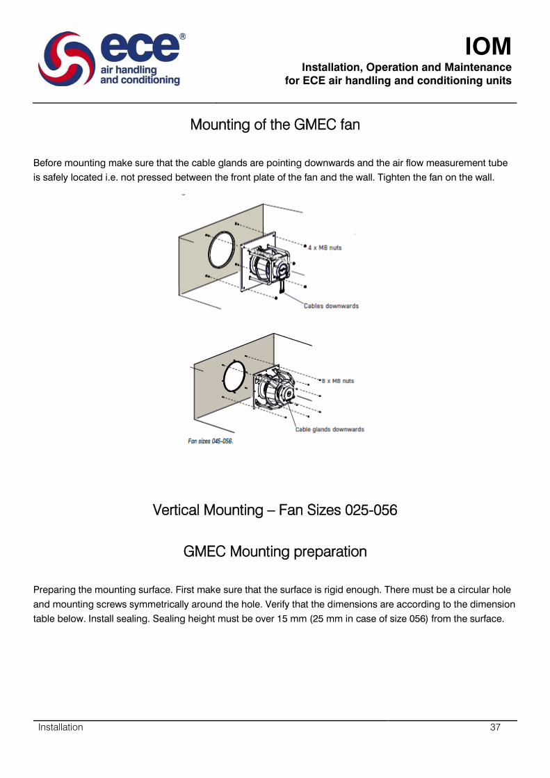
Mounting of the GMEC fan
Before mounting make sure that the cable glands are pointing downwards and the air flow measurement tube
is safely located i.e. not pressed between the front plate of the fan and the wall. Tighten the fan on the wall.
Vertical Mounting – Fan Sizes 025-056
GMEC Mounting preparation
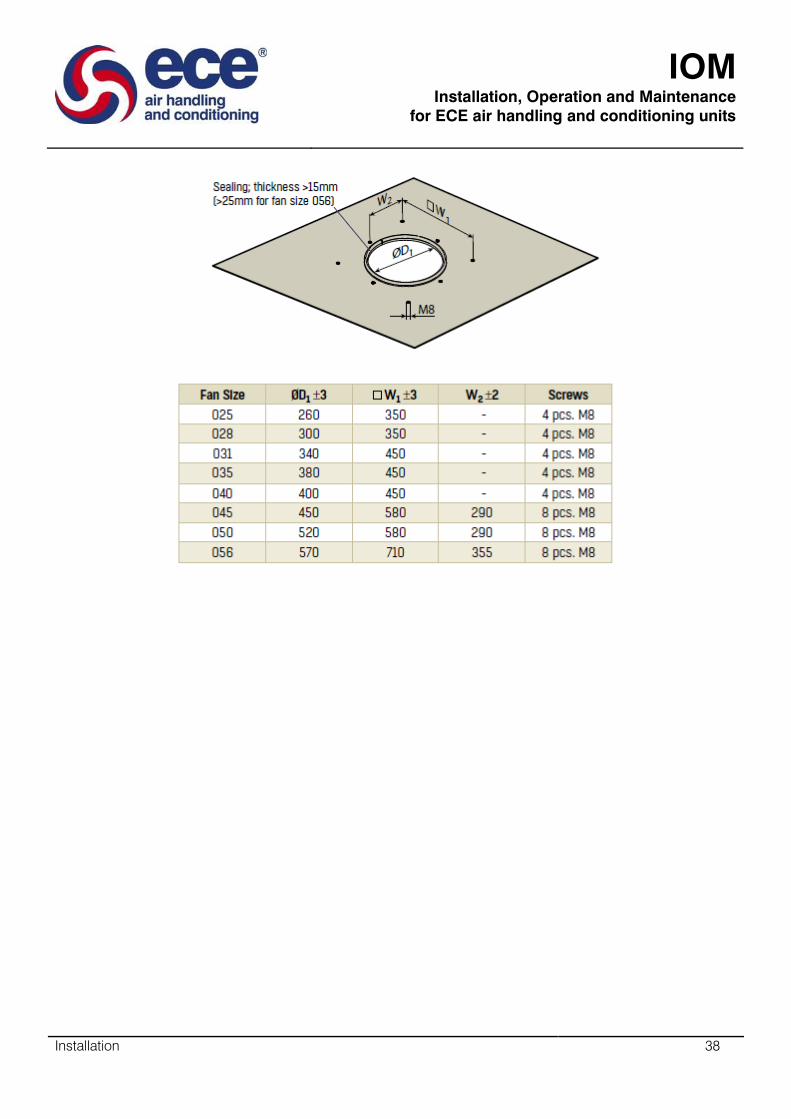
Preparing the mounting surface. First make sure that the surface is rigid enough. There must be a circular hole
and mounting screws symmetrically around the hole. Verify that the dimensions are according to the dimension
table below. Install sealing. Sealing height must be over 15 mm (25 mm in case of size 056) from the surface.
IOM
Installation, Operation and Maintenance
for ECE air handling and conditioning units
Installation 38
IOM
Installation, Operation and Maintenance
for ECE air handling and conditioning units
Installation 39
GMEC Mounting of the fan
Before mounting make sure that the air flow measurement tube is safely located i.e. not pressed between the
front plate of the fan and the mounting surface. Tighten the fan on the place.
GMEC Grounding
Motor is grounded through the motor supply cable. If extra grounding is needed, grounding can be done with a
separate cable from the fan motor to the casing of the Air Handling Unit. The motor has a grounding marking
next to the grounding point.
Motor is grounded through the motor power supply cable. If extra grounding is needed, grounding can be done
with a separate cable from the fan motor to the casing of the Air Handling Unit. The motor has a grounding
marking next to the grounding point.

IOM
Installation, Operation and Maintenance
for ECE air handling and conditioning units
Installation 40
Fitting the GMEC accessories
The inlet protective screen can be fitted directly to the front plate of the fan or outside Air Handling Unit to the
inlet opening.
GMEC Electrical Connections
All electrical connections must be wired by authorized personnel only. The necessary electrical and safety
precautions must be taken into account. Connections must be done according to the instructions.
Installation of the GPEB fan
The fan is secured to a base by bolts in mounting holes across anti-vibration mountings. The base must be
level and stable. The fan must only be mounted in a horizontal plane. Either the fan or the base is mounted on
anti-vibration mountings.
Fitting the GPEB accessories
The fan should normally be connected to the air handling unit by means of flexible connection or other type of
gasket to eliminate vibration transfer from fan to AHU casing.
Providing necessary grounding for the accessories is within the constructor’s field of responsibility.
Inlet protective screen can be fitted directly to the front frame or outside AHU to the inlet opening.
GPEB Safety regulations
The fan does not meet the provisions of CE labelling (i.e. it has an impeller without guard). The fan must be
installed in accordance with EN 292/294.
GPEB Electrical connections
All electrical connections must be wired by authorised personnel only. The necessary electrical and safety
precautions must be taken into account. If the motor is operated across a frequency converter, the connections
must be made according to the instructions of the frequency manufacturer. The motor must be grounded.

IOM
Installation, Operation and Maintenance
for ECE air handling and conditioning units
Installation 41
SDPV-10 Po Inset Mounting (IP 44)
Connect according to the diagram. Mount the inner case to the wall with the connections pointing down. Mount
cover with nut to the wall. Push dial in place at off position.
SDPV-10 Surface Mounting (IP 54)
Mount the case to the wall together with included grommets. Connect according to the diagram. Mount inner
case in surface mounting case with included screws. Mount cover with nut to surface mounting case. Push dial
in place at off position. When needed a 5 mm hole for condensation water is to be drilled at the bottom of the
surface mounting case.
SDPV-10 Isolation and wiring
The cable connecting the device control should not exceed 4 m. For a cable length between 4 and 12 m we
recommend using a shielded cable. For cable longer than 12 m use the SDPV-230 device.
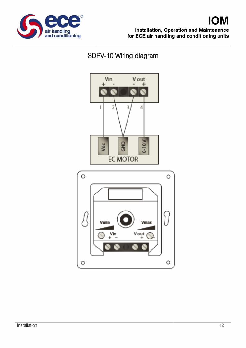
IOM
Installation, Operation and Maintenance
for ECE air handling and conditioning units
Installation 42
SDPV-10 Wiring diagram
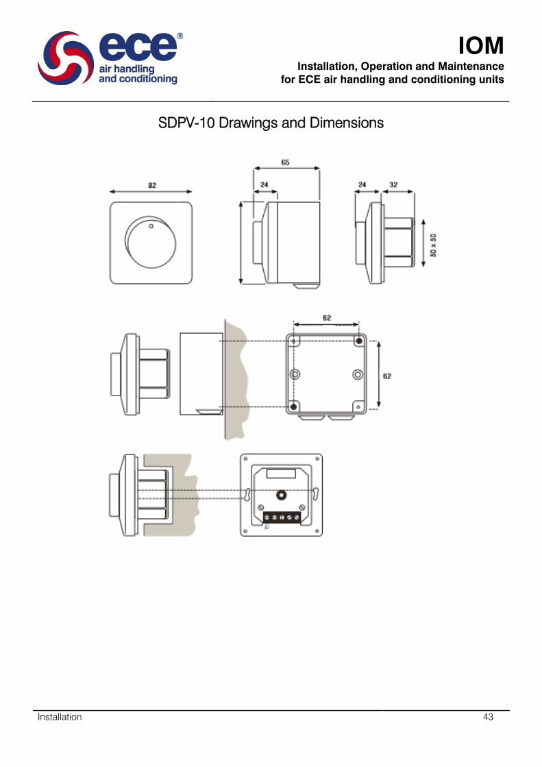
IOM
Installation, Operation and Maintenance
for ECE air handling and conditioning units
Installation 43
SDPV-10 Drawings and Dimensions

IOM
Installation, Operation and Maintenance
for ECE air handling and conditioning units
Installation 44
SDPV-230 Inset Mounting
Break mains voltage. Connect according to diagram. Mount the inner case to the wall with the connections
pointing down. Mount cover with nut to the wall. Push dial in place at off position.
SDPV-230 Surface Mounting
Break mains voltage. Mount surface mounting case to the wall together with included grommets. Connect
according to diagram. Mount inner case in surface mounting case with included screws. Mount cover with nut
to surface mounting case. Push dial in place at off position. When needed a 5 mm hole for condensation water
is to be drilled at the bottom of the surface mounting case.
Break the mains voltage and the mounting surface which will be cased closer to the
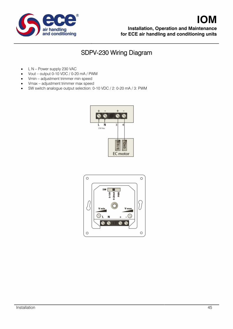
IOM
Installation, Operation and Maintenance
for ECE air handling and conditioning units
Installation 45
SDPV-230 Wiring Diagram
L N – Power supply 230 VAC
Vout – output 0-10 VDC / 0-20 mA / PWM
Vmin – adjustment trimmer min speed
Vmax – adjustment trimmer max speed
SW switch analogue output selection: 0-10 VDC / 2: 0-20 mA / 3: PWM
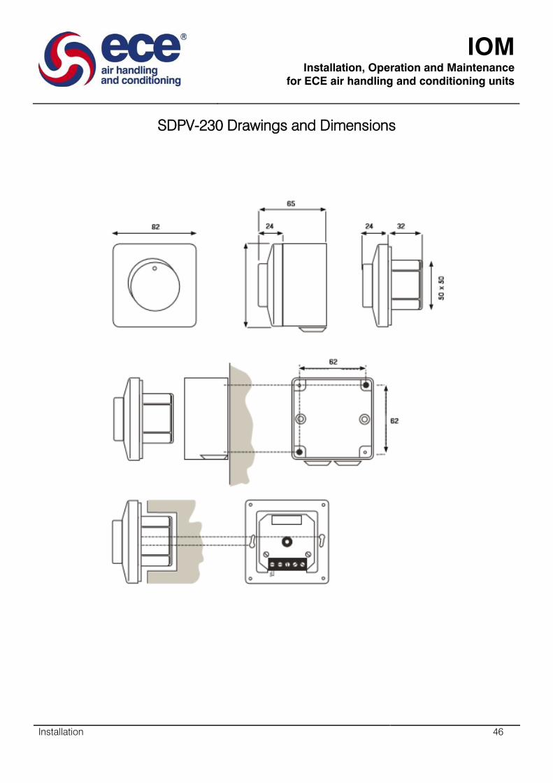
IOM
Installation, Operation and Maintenance
for ECE air handling and conditioning units
Installation 46
SDPV-230 Drawings and Dimensions

IOM
Installation, Operation and Maintenance
for ECE air handling and conditioning units
Installation 47
EEID Compatibility
Our EEID speed controller is suitable for use with single phase voltage controllable motors.
EEID Inset Mounting
Break (isolate) mains voltage. Connect according to diagram. Mount Inner case to the wall with connections
pointing down. Turn on the mains voltage and controller. Adjust min. speed with insulated screwdriver and turn
off controller. Mount cover with nut to the wall. Push knob in place at off position.
EEID Surface Mounting
Break (isolate) mains voltage. Mount surface mounting case to the wall together with included grommets.
Connect according to the diagram. Turn on mains voltage and controller. Adjust min. speed with insulated
screwdriver and turn off controller. Mount cover with nut to surface mounting case. Push control dial in place at
off position.
EEID Change of fuse
Break (isolate) mains voltage. Undo control dial by first turning it to the right beyond end stop and then pull
towards you. Remove the nut. Remove fuse holder with a screwdriver. Change fuse. Replace components in
reverse order. Use only recommended fuses (Approved, fast, with high breaking capacity).
EEID Motor protection
If motors are fitted with thermostat (tk) overheat protection it is recommended to use the EEDS range to utilise
the feature.
By breaking the mains voltage, the undo control dial is done by first turning it to the right beyond and stop and
then pull towards you. This will be
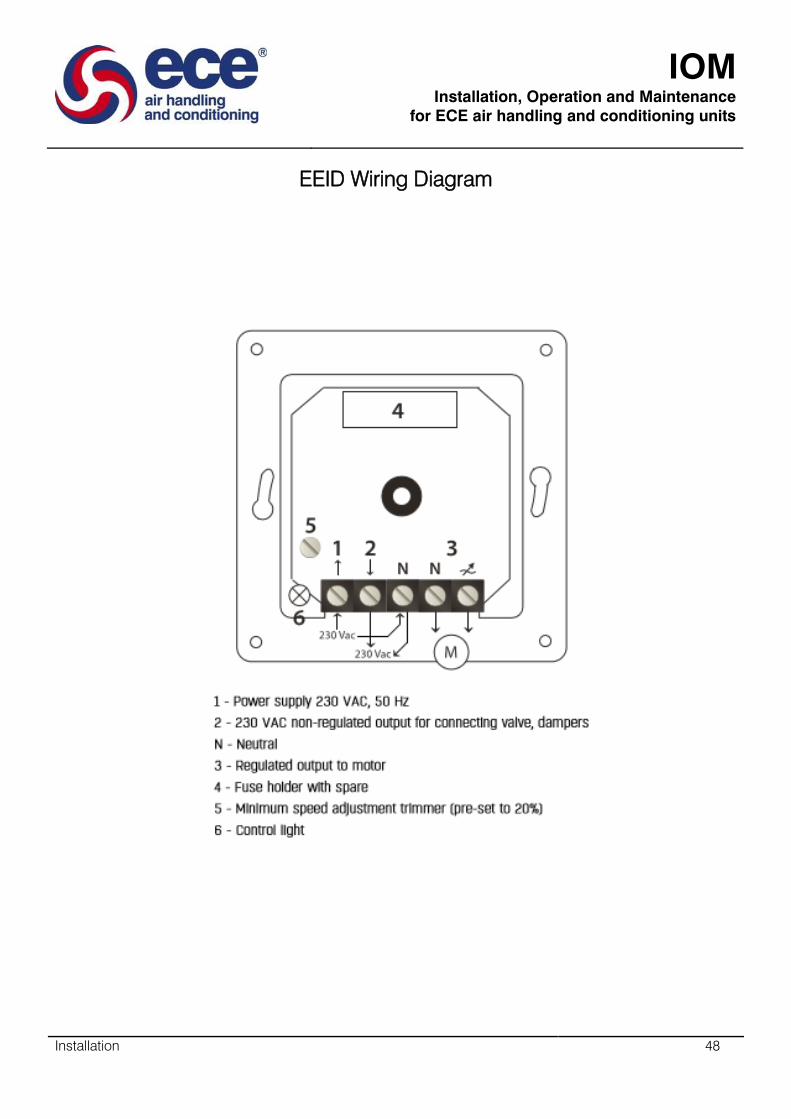
IOM
Installation, Operation and Maintenance
for ECE air handling and conditioning units
Installation 48
EEID Wiring Diagram
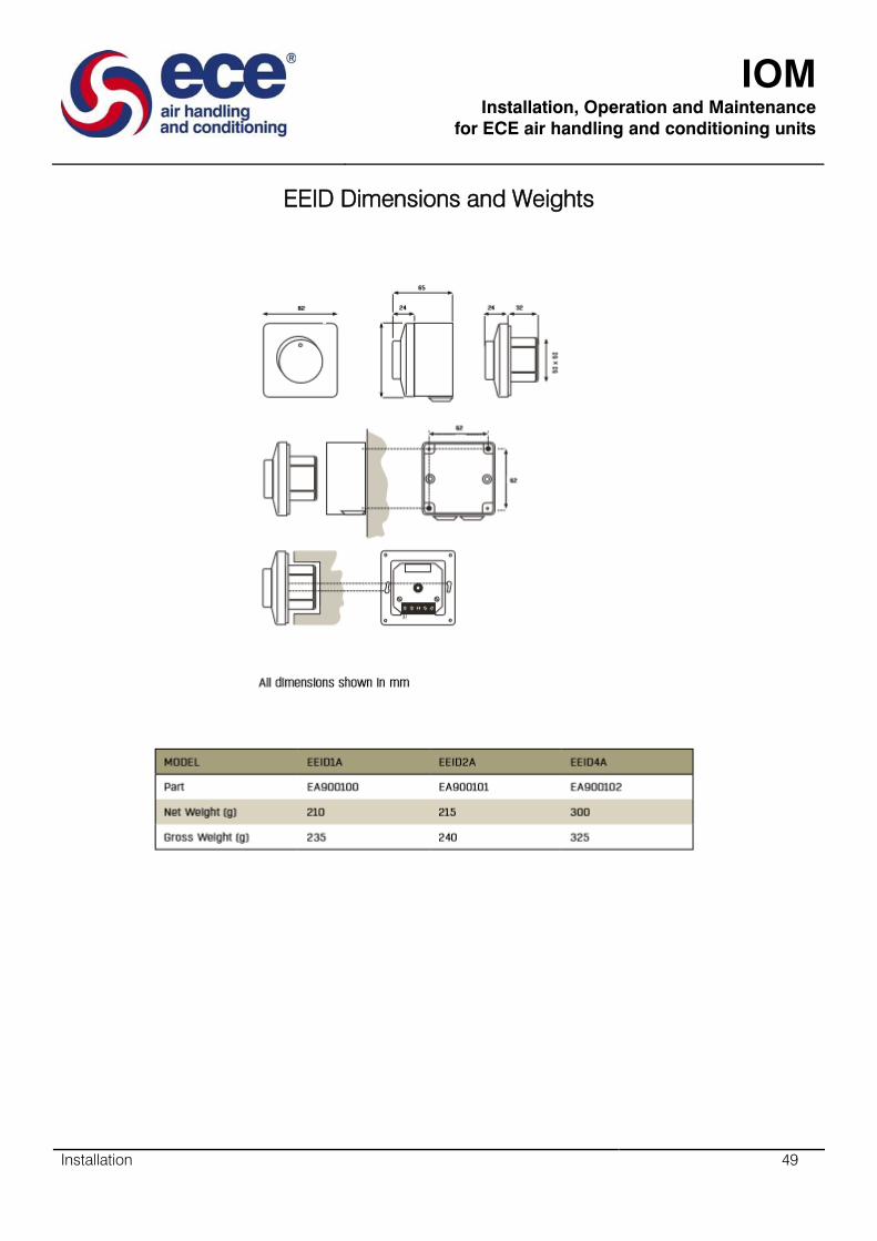
IOM
Installation, Operation and Maintenance
for ECE air handling and conditioning units
Installation 49
EEID Dimensions and Weights

IOM
Installation, Operation and Maintenance
for ECE air handling and conditioning units
Installation 50
VSD2H Control Keypad
The control keypad can be usedn for setting the frequency converter’s parameters, reading statuzs data, and
giving control commands. It is detachable and can be operated externally being connected via a cable to the
main unit. There are two accessory kits available+
ACC/VSD2H/Hand Held Kit
This enables the keypad to be detached from the unit and to be used as a hand held unit connected to the VSD
by a 2 m cable.
ACC/VSD2H/Door Mounting Kit
This enables the keypad to be detached from the unit and to be mounted in the panel door connected to the
VSD by a 2 m cable.
The standard test keypad features an alphanumeric display with seven indicators for run status (READY, RUN,
STOP, ALARM, FAULT, FWD, REV). and three indicators for control source (I/O, KEYPAD, BUS). There are also
two text lines displaying description (of menu, value or fault) and location (reference to menu and parameter) or
value (numerical, textual values).
A replacement advanced commissioning keypad is available as an accessory (ACC/VSD2H GRAPHIC
DISPLAY). The commissioning keypad can also be used to store the parameter settings and transport them to
another drive. The top row is the drive status field, and the second row is the location field describing the
position in the selection menu. The remaining three rows can be used for display of information. The
commissioning keypad has extra features (help and information displays, favourites, multi-monitor of 9 selected
values).

IOM
Installation, Operation and Maintenance
for ECE air handling and conditioning units
Installation 51
Hardware
The keypad has nine buttons which are used for controlling the drive, setting parameters, and monitoring
values. The buttons are the same for both types of keypad.
The keypad is the control source by default (i.e. Local) but it can be changed to remote at any time by pressing
the LOC/REM button. (The control source has to be changed to Remote/Fieldbus for the NXNI or NXIP to
control the drive.)
The main menu consists of 7 individual items which are browsed using up and down buttons, the submenus
under these menus are then browsed by selecting OK.
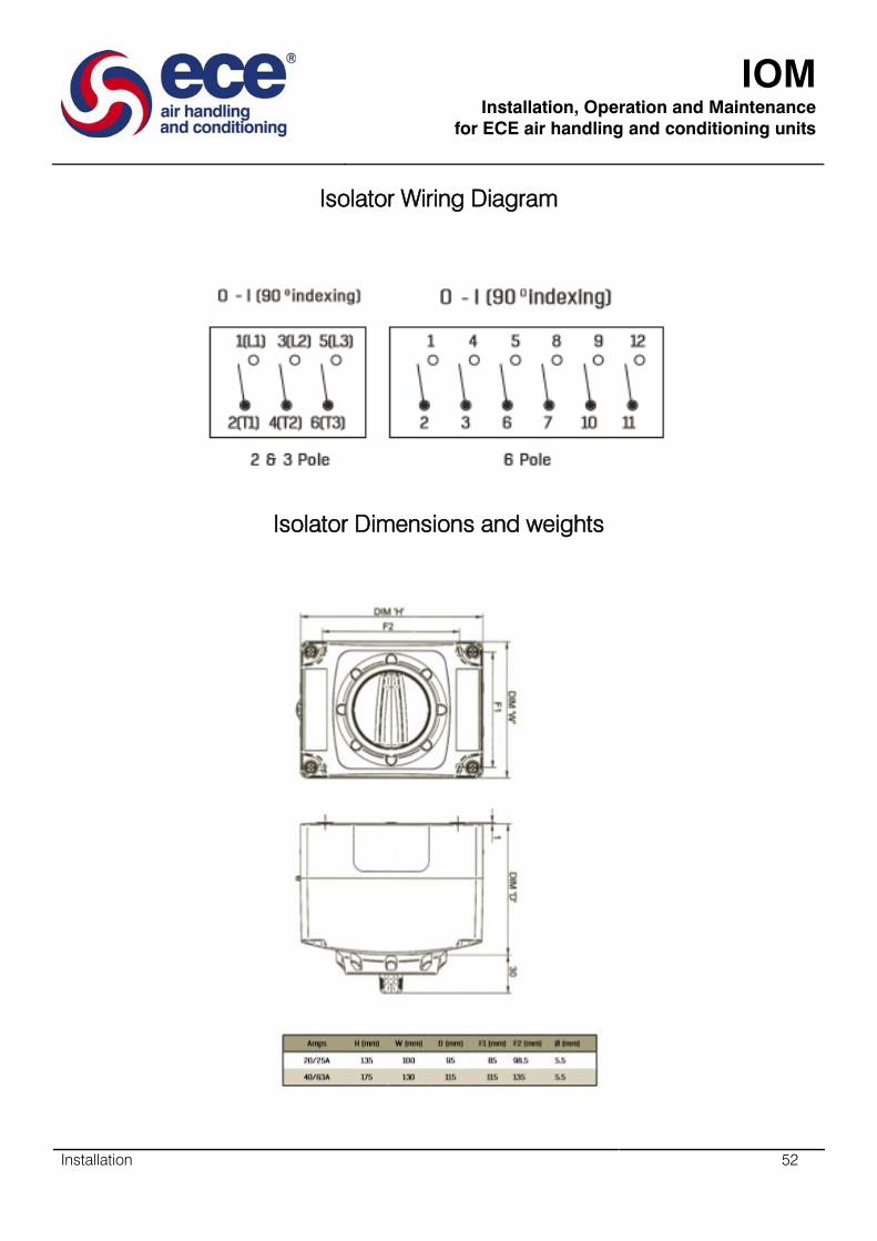
IOM
Installation, Operation and Maintenance
for ECE air handling and conditioning units
Installation 52
Isolator Wiring Diagram
Isolator Dimensions and weights
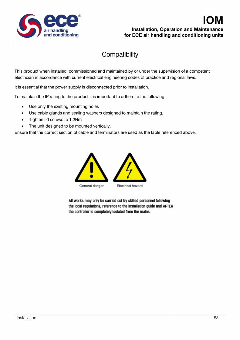
IOM
Installation, Operation and Maintenance
for ECE air handling and conditioning units
Installation 53
Compatibility
This product when installed, commissioned and maintained by or under the supervision of a competent
electrician in accordance with current electrical engineering codes of practice and regional laws.
It is essential that the power supply is disconnected prior to installation.
To maintain the IP rating to the product it is important to adhere to the following.
Use only the existing mounting holes
Use cable glands and sealing washers designed to maintain the rating.
Tighten lid screws to 1.2Nm
The unit designed to be mounted vertically.
Ensure that the correct section of cable and terminators are used as the table referenced above.

IOM
Installation, Operation and Maintenance
for ECE air handling and conditioning units
54
RAC Fan Type & Speed Control

IOM
Installation, Operation and Maintenance
for ECE air handling and conditioning units
RAC Fan Type & Speed Control 55
GMEB Fan Technical Description
The fan is used to generate a desired air volume at a given pressure rise that corresponds to the pressure
losses in the duct system to which the fan is connected, and internal losses inside of the Air Handling Unit.
The plug fan is intended to be used inside of the Air Handling Unit.
Design
1 .Front plate
2 .Inlet cone
3. Impeller and hub
4. Motor
5. Base frame
6. Motor bracket
7. Front plate support (fan size 056 and bigger)
8. Vibration dampers (optional)
9. Built-on frequency converter (optional)
10. Frequency converter mounting plate (optional)
IOM
Installation, Operation and Maintenance
for ECE air handling and conditioning units
RAC Fan Type & Speed Control 56
GMEB Operating conditions
The standard operation temperature range of the fan is -20°C - + 40°C.
If they are operated in conditions where the ambient temperature is higher, the rated output will as a rule have
to be reduced. See the instructions of the motor manufacturer.
“The fans are designed to be used as parts of equipment. They are not ready for use as a stand-alone product
and the standard version does not have protection against body contact, the appropriate protective measures
are to be taken according to EN 292/294.
Only operate the fan up to the maximum permissible speed given in the information on the fan rating plate.
GMEB Motors
Both AC- and PM-motors can be used with GMPM and GMEB plug fans.
AC- motors are IEC standard IE2 or IE3 motors. The motors are equipped with a thermistor and they are
designed for a frequency converter use. Admissible environmental temperature: from -15° up to +40° C.
GMEB Frequency Converters
All fans used in an Air Handling Unit in the European Union area shall be equipped with a speed controller in
accordance with the Regulation 1253/2014.
GMEB Fan impeller
The impeller is made of sheet steel, welded and painted with 60 µm thick epoxy powder paint, (colour: RAL
6029, green). The impellers are dynamically balanced to ISO Standard 1940-1973 G 2.5 sizes (022-031) at the
maximum speed. The vibration level of the fan is below 7.1mm/s RMS.
GMEB Fan Inlet
The design of the fan inlet is vitally important to the fan efficiency and the low level of sound generated by the
fan. The inlet cones are deep-drawn in one piece and are fitted to the end panel. The inlet cone and end panel
are made of galvanized sheet steel.

IOM
Installation, Operation and Maintenance
for ECE air handling and conditioning units
RAC Fan Type & Speed Control 57
GMEB Motor base with base frame
The motor base is made of galvanized sheet steel or of welded sheet steel and painted with 60 µm thick expoxy
powder paint (colour: RAL 7005, dark grey). The base frame is made of galvanised steel (size 022 – 071) or of
steel, welded and hot-dip galvanised (size 080-140 and sizes 050-071 if motor is IEC 160).
GMEB Hub
The fan impeller is either equipped with a standard hub (separate for each motor size) or with a taper lock type
hub. The standard hub is made of aluminium or welded steel. The taper lock hub (sizes 022-100) is made of
cast iron and phosphatised.
GMEB Air flow sensor
The air flow sensor is used for measuring the airflow of the plug fans. The method is based on differential
pressure. The pressure is measured at a specific point in the inlet cone and the reference pressure is measured
upstream of the inlet cone. The air flow sensor is supplied factory mounted in the inlet cone.
GMEB Directive for machinery
The GMEB fan is not a product which is ready for use but it is designed for mounting in an air handling unit. The
air handling unit manufacturer must follow all instructions according to Directive for Machinery, EMC Directive
and Low Voltage Directive as well as use all necessary protective measures.
The airflow sensor that is used for the airflow of all of the plug fans. The method is based on differential
pressure. The pressure of the
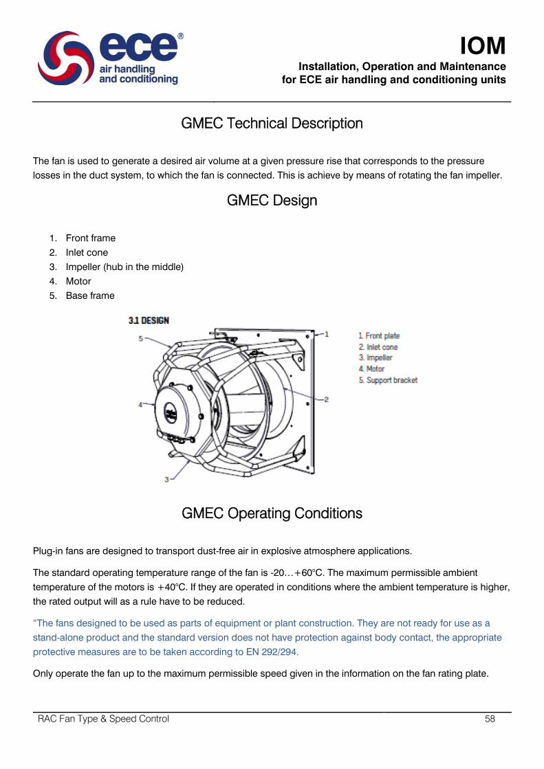
IOM
Installation, Operation and Maintenance
for ECE air handling and conditioning units
RAC Fan Type & Speed Control 58
GMEC Technical Description
The fan is used to generate a desired air volume at a given pressure rise that corresponds to the pressure
losses in the duct system, to which the fan is connected. This is achieve by means of rotating the fan impeller.
GMEC Design
1. Front frame
2. Inlet cone
3. Impeller (hub in the middle)
4. Motor
5. Base frame
GMEC Operating Conditions
Plug-in fans are designed to transport dust-free air in explosive atmosphere applications.
The standard operating temperature range of the fan is -20…+60°C. The maximum permissible ambient
temperature of the motors is +40°C. If they are operated in conditions where the ambient temperature is higher,
the rated output will as a rule have to be reduced.
“The fans designed to be used as parts of equipment or plant construction. They are not ready for use as a
stand-alone product and the standard version does not have protection against body contact, the appropriate
protective measures are to be taken according to EN 292/294.
Only operate the fan up to the maximum permissible speed given in the information on the fan rating plate.
IOM
Installation, Operation and Maintenance
for ECE air handling and conditioning units
RAC Fan Type & Speed Control 59
GMEC Motors
The motors are three-phase motors to IEC-standard with degree of protection IP55 and can be equipped with
thermal overload protection consisting of a thermoswitch or thermistor. The motors meet the requirements of
IEC-standard, VDE and DIN norms. The motors are suitable for operation across the frequency converter. The
max permissible control frequency is specified on the motor rating plate. The minimum control frequency is 10
Hz.
Integral motors are 3-phase 400 VAC motors with integrated frequency converter. Degree of protection is IP 55
and allowed ambient temperature is – 10… +40°C. Max control frequency is specified on the motor plate, min
control frequency is 10 Hz.
For Demand Proportional Drives.
GMEC Important information
ECE fans comply with the requirements for health and safety of the EC Machinery Directive.
All fans leave the factory after being subjective to testing.
These instructions are intended for use by professional service staff. The installation, commissioning and
operation of the fans must be carried out by professional staff who are familiar with the safety regulations.
Tools and protective equipment necessary for preventing accidents from occurring while installing and
operating the fan must be used/worn in accordance with the local safety regulations.
All personnel involved with the product must carefully study this operating manual and diligently comply with all
orders and instructions.
ECE does not accept responsibility for any damage that can be attributed to non-observance of these
instructions.

IOM
Installation, Operation and Maintenance
for ECE air handling and conditioning units
RAC Fan Type & Speed Control 60
SDPV-10 Potentiometer
Features:
Minimum (vmin) and maximum (Vmax) output setting by internal trimmer.
IP rating flush mounting: IP44, surface mounting: IP54.
Enclosure external: plastic ASA, RAL 9010 white-ivory
Enclosure internal: polyamide according to IEC 60335
Operating temperature: 0…40°C
Supply (Vin 3-15 VDC
Vmin 10-70 % Vin
Vmax 30-100 % vin
Load > 2 kΩ
Consumption < 10 mA incl. load

IOM
Installation, Operation and Maintenance
for ECE air handling and conditioning units
RAC Fan Type & Speed Control 61
SDPV-10 Description
These potentiometers are designed to control fans equipped with an EC motor or in any application where a
DC control signal of 0-10VDC is required; such as demand proportional drives.
It is mounted in a splash water proof design enclosure and can be used for inset as well as for surface
mounting.
The SDPV-10 is supplied with customer adjustable min and max settings pre-set from the factory for Vmin 20%
and Vmax 100%.
A supply voltage between 3 and 15 VDC is required to provide an infinitely variable output signal between two
internally selectable positions: Vmin and Vmax. The load may not be lower than 2 k0hm (R>2 k0hm).
SDPV-10 Range
SDPV-10 Technical Data
Supply (Vin) 3-15 VDC
Vmin 10-70 % Vin Vmax 30-100 % Vin
Load < 10 mA incl. load
Off position
Enclosure external: plastic ASA, RAL 9010 white-ivory
Enclosure Internal: polymamide according to IEC 60335
Operating temperature: 0…40°C
This potentiometer is developed to control fans equipped with an EC motor or other demand proportional drive
requiring 0-10VDC input. It is mounted in a splash water proof housing and can be used for inset as well as for
surface mounting. The potentiometer requires a supply between 3 VDC and 15 VDC, and it provides a stepless
output signal between voltage Vmin and voltage Vmax. Vmin and Vmax are internally selectable. Position 0 is
the off-position. The load cannot be lower than 2 kΩ (R>2 kΩ).
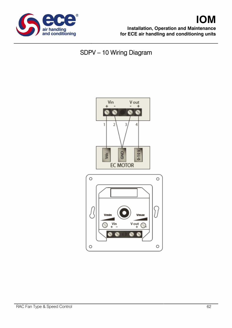
IOM
Installation, Operation and Maintenance
for ECE air handling and conditioning units
RAC Fan Type & Speed Control 62
SDPV – 10 Wiring Diagram

IOM
Installation, Operation and Maintenance
for ECE air handling and conditioning units
RAC Fan Type & Speed Control 63
SDPV-230 – Room Potentiometer
For demand Proportional Drives
SDPV-230 Features
Voltage supply: 230 VAC, 50/60 Hz
Selectable output: 0-10 V, 0-20 mA and PWM.
Load: 0-10 V and PWM > 2kΩ / 0-20 mA < 500Ω
Minimum (Vmin) and maximum (Vmax) output setting by internal trimmer
IP rating flush mounting: IP44, surface mounting: IP54
Enclosure external: plastic ASA, RAL 9010 white-ivory
Enclosure internal: polyamide according to IEC 60335
Operating temperature: 0…40°C.
SDPV-230 Description
This potentiometer is developed to control fans equipped with an EC motor or demand proportional drives
without a 10VDC output. It is mounted in a splash water proof housing and can be used for inset aswell as for
surface mounting.
The potentiometer needs a supply of 230 VAC, and gives a stepless output signal of 0-10 VDC or 0-20 mA and
PWM between voltage Vmin and voltage Vmax. Position 0 is the off-position. The load cannot be lower than 2
kΩ (R>2 kΩ) in 0-10 V output mode or higher than 500 Ω if 0-20 mA.
SDPV-230 Range

IOM
Installation, Operation and Maintenance
for ECE air handling and conditioning units
RAC Fan Type & Speed Control 64
SDPV-230 Technical Data
Mode 0-10 V 0-20 mA PWM
Output 0, 1-10 V 0, 2-20 mA 0, 10-100 % PWM
Vmin 1 – 7 VDC 2-10 mA 10-70 % PWM
Vmax 3 – 10 VDC Vmax: 6-20 mA 30-100 % PWM
Enclosure external: plastic, ASA, RAL 9010 white-ivory
Enclosure internal: polyamide According to IEC 60335
Operating temperature: 0…40°C
This potentiometer is developed to control fans equipped with an EC-motor. It is mounted in a splash water
proof housing and can be used for inset as well as forn surface mounting.
The potentiometer needs a supply of 230 VAC, and gives a stepless output signal of 0-10 VDC or 0-20 mA and
PWM between voltage Vmin and voltage Vmax. Position 0 is the off-position. The load cannot be lower than 2
kΩ (R>2 k Ω) in 0-10 V output mode or higher than 500 Ω if 0-20 mA output is selected.

IOM
Installation, Operation and Maintenance
for ECE air handling and conditioning units
RAC Fan Type & Speed Control 65
SDPV – 230 Wiring Diagram

IOM
Installation, Operation and Maintenance
for ECE air handling and conditioning units
RAC Fan Type & Speed Control 66
EEID – Electronic Single Phase
Independent drive
EEID Features
Independent control of fan speed, infinitely variable from max to min with off position.
Supply 230 VAC, 50/60 Hz, 1 phase
IP54 Surface IPIP44 inset ingress protection rating
Two wire control
]Clear indication light
Commissioning adjustable minimum speed pre-set to 20% via internal potentiometer
Fuse 5*20mm, spare included
RAL9010 white ivory enclosure and face. Internal polyamide.
Mac ambient temperature: 50°C.
EEID Description
Our EEID drive is a compact wall mounted speed controller designed for single phase voltage controllable
motors (230 VAC, 50-60 Hz). It varies the output voltage by using a optotriac phase angle control.
Operational status is indicated by an LED, while a hand controlled dial provides an on/off switch and the means
to infinitely control fan speed.
Suitable for inset or surface or surface mounting with the splash-resistant housing provided.
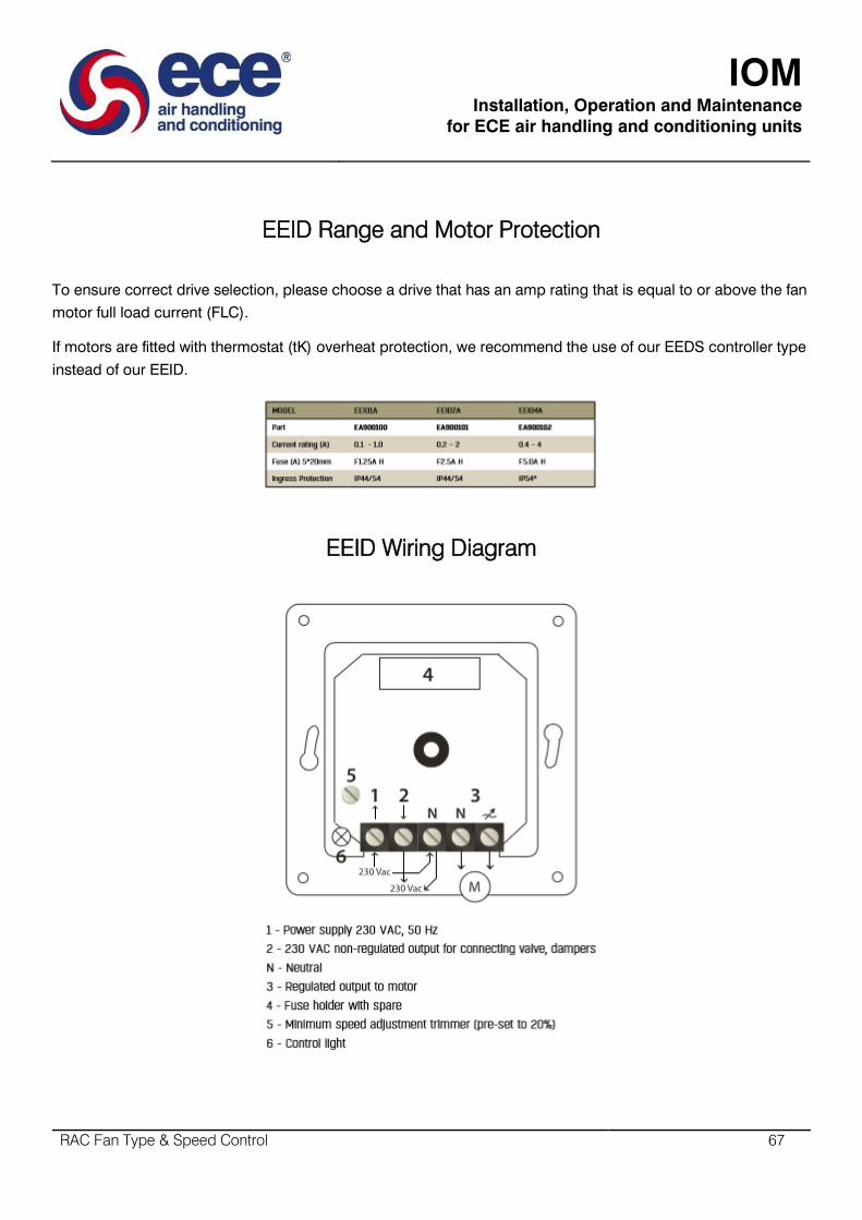
IOM
Installation, Operation and Maintenance
for ECE air handling and conditioning units
RAC Fan Type & Speed Control 67
EEID Range and Motor Protection
To ensure correct drive selection, please choose a drive that has an amp rating that is equal to or above the fan
motor full load current (FLC).
If motors are fitted with thermostat (tK) overheat protection, we recommend the use of our EEDS controller type
instead of our EEID.
EEID Wiring Diagram

IOM
Installation, Operation and Maintenance
for ECE air handling and conditioning units
RAC Fan Type & Speed Control 68
Trend - VSD2H Variable Isolator Speed Drives
VSD2H Variable Isolator Speed Description
Variable motor speed drives suitable for HVAC applications where the speed control of motors can be applied.
They convert fixed frequency and voltage from the mains supply to variable frequency and voltage enabling
motors to be used with maximum efficiency resulting in significant energy savings.
The control keypad can be mounted on the front of the unit or can be remotely connected by way of a 2 m
cable and mounted on a panel or used as a handheld unit.
The keypad accesses the startup wizard which facilitates the application configuration for the user (pump/fan,
PID loops, multi-pump, cascade control).
VSD2H Variable Isolator Speed Features
380 to 480 Vac 3 phase
Current rating range from 3 A to 310 A.
IP21 and IP54 models available
Optional Trend system network interfaces (NXNI or NXIP)
Application configurable using wizard for a number pump or fan scenarios.
Real time clock fitted with battery
Integrated RFI filter for typical building installation
Versatile PC tools available
Slim, space-saving, “bookshell” design
Varnished printed circuit boards to maximise reliability.
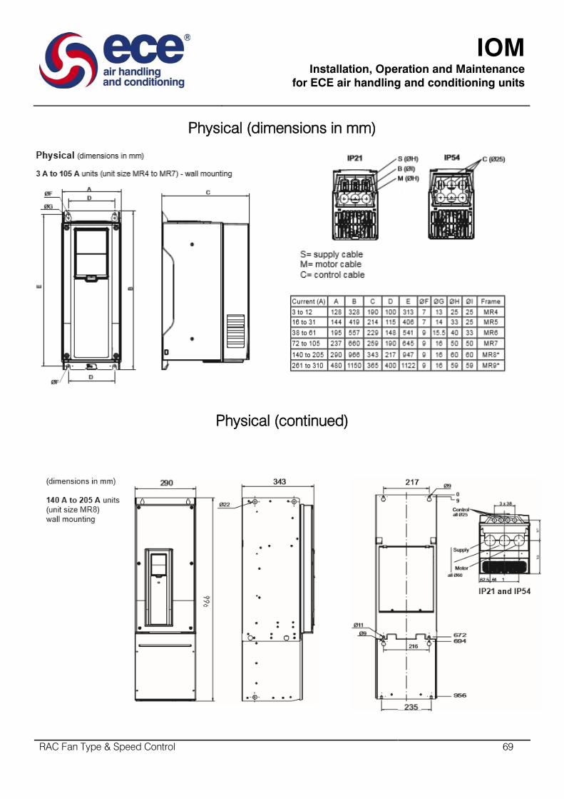
IOM
Installation, Operation and Maintenance
for ECE air handling and conditioning units
RAC Fan Type & Speed Control 69
Physical (dimensions in mm)
Physical (continued)
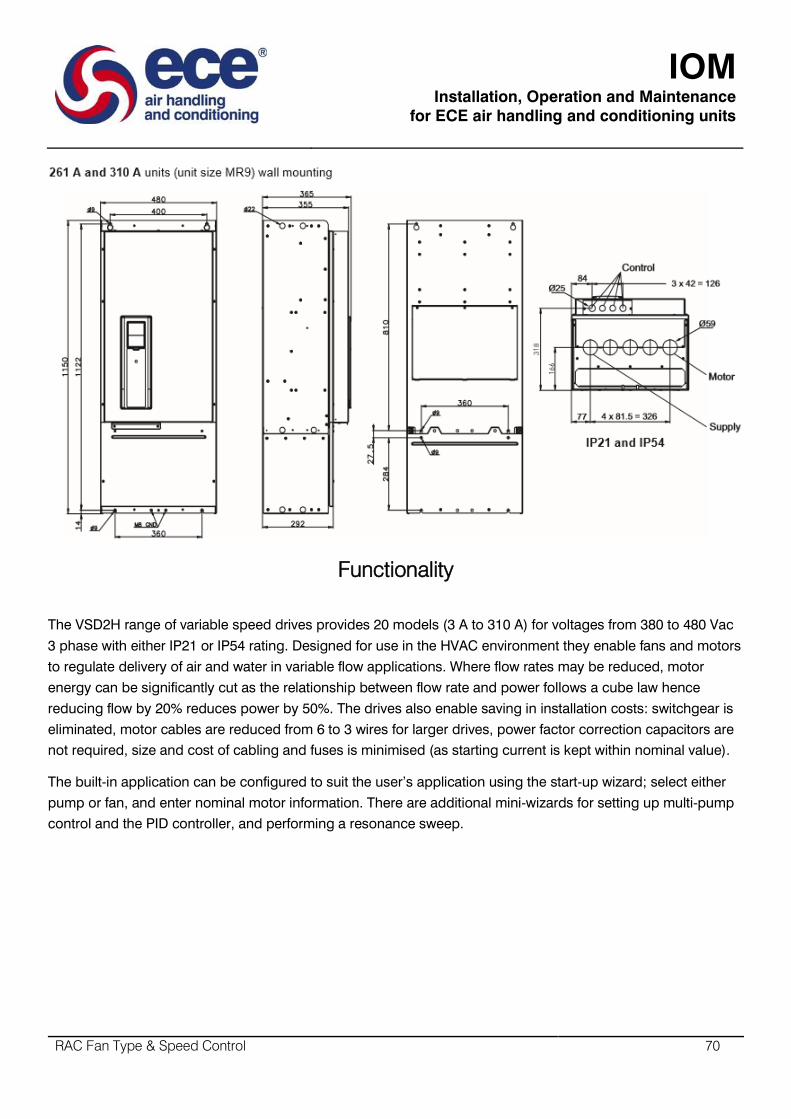
IOM
Installation, Operation and Maintenance
for ECE air handling and conditioning units
RAC Fan Type & Speed Control 70
Functionality
The VSD2H range of variable speed drives provides 20 models (3 A to 310 A) for voltages from 380 to 480 Vac
3 phase with either IP21 or IP54 rating. Designed for use in the HVAC environment they enable fans and motors
to regulate delivery of air and water in variable flow applications. Where flow rates may be reduced, motor
energy can be significantly cut as the relationship between flow rate and power follows a cube law hence
reducing flow by 20% reduces power by 50%. The drives also enable saving in installation costs: switchgear is
eliminated, motor cables are reduced from 6 to 3 wires for larger drives, power factor correction capacitors are
not required, size and cost of cabling and fuses is minimised (as starting current is kept within nominal value).
The built-in application can be configured to suit the user’s application using the start-up wizard; select either
pump or fan, and enter nominal motor information. There are additional mini-wizards for setting up multi-pump
control and the PID controller, and performing a resonance sweep.

IOM
Installation, Operation and Maintenance
for ECE air handling and conditioning units
RAC Fan Type & Speed Control 71
Hardware
Unit: The unit is housed in a slim, space saving, bookshelf style enclosure that should be mounted
vertically on a wall or on the back panel of a cubicle. Enough space should be left round the unit for
cooling. Most units have 4 point mounting with two keyhole slots.
System: The drive consists of the main unit, the cover, and a detachable keypad unit.
The unit will be housed in a slim, space saving, bookshelf style enclosure that should be mounted vertically on
a wall or on the back of a cubicle. Enough space should be left around the unit for cooling. Most units have 4
point mounting with two keyhole slots.
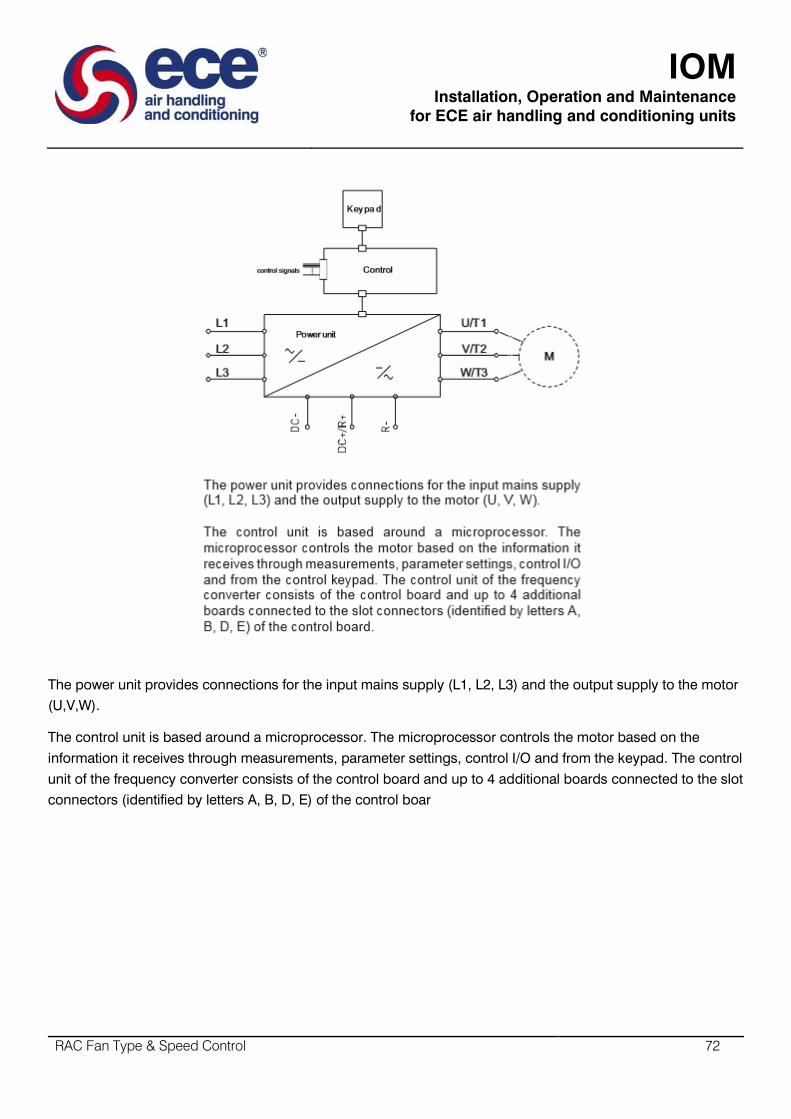
IOM
Installation, Operation and Maintenance
for ECE air handling and conditioning units
RAC Fan Type & Speed Control 72
The power unit provides connections for the input mains supply (L1, L2, L3) and the output supply to the motor
(U,V,W).
The control unit is based around a microprocessor. The microprocessor controls the motor based on the
information it receives through measurements, parameter settings, control I/O and from the keypad. The control
unit of the frequency converter consists of the control board and up to 4 additional boards connected to the slot
connectors (identified by letters A, B, D, E) of the control boar
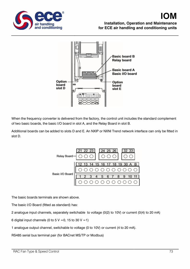
IOM
Installation, Operation and Maintenance
for ECE air handling and conditioning units
RAC Fan Type & Speed Control 73
When the frequency converter is delivered from the factory, the control unit includes the standard complement
of two basic boards, the basic I/O board in slot A, and the Relay Board in slot B.
Additional boards can be added to slots D and E. An NXIP or NXNI Trend network interface can only be fitted in
slot D.
The basic boards terminals are shown above.
The basic I/O Board (fitted as standard) has:
2 analogue input channels, separately switchable to voltage (0(2) to 10V) or current (0(4) to 20 mA)
6 digital input channels (0 to 5 V =0, 15 to 30 V =1)
1 analogue output channel, switchable to voltage (0 to 10V) or current (4 to 20 mA).
RS485 serial bus terminal pair (for BACnet MS/TP or Modbus)

IOM
Installation, Operation and Maintenance
for ECE air handling and conditioning units
RAC Fan Type & Speed Control 74
The defaults for the analogue inputs and output are indicated in the diagram below; they may be changed
using the DIP switches (see below).

IOM
Installation, Operation and Maintenance
for ECE air handling and conditioning units
RAC Fan Type & Speed Control 75
“The control board can be powered externally by connecting an external power source to terminal 30. This voltage is
sufficient for parameter setting and for keeping the control unit active. Note however that the measurements of the main
circuit (e.g. DC-link voltage,Unit temperature) are not available when the mains is not connected.”

IOM
Installation, Operation and Maintenance
for ECE air handling and conditioning units
RAC Fan Type & Speed Control 76
The Basic Relay Board (fitted as standard) has:
2 changeover relay output channel
1 thermistor input channel
An optional system network interface can be fitted into the VSD2H drive. It is plugged into slot D, and enables
the unit to be monitored and controlled from supervisors, and from the controllers. There are the IQ system
current loop Lan interface. NXNI (which provides a standard four wide current loop Lan terminal set), and the
Ethernet interface, nxip. See NXNI data sheet TA200826 for details. Note that the NXNI allows the unit to be
monitored by all controllers, but it can only be written to by IQ3, IQ4 or IQeco controllers.

IOM
Installation, Operation and Maintenance
for ECE air handling and conditioning units
RAC Fan Type & Speed Control 77
DIP Switch
The 4 DIP switches have 3 functional positions, left, middle and right. The middle position is used for test mode. The
switches are used to set the following parameters:
Switch 1: RS485 fieldbus Terminator resistor, on or off (default off)
Switch 2: Analogue Output 1, current or voltage (default current)
Switch 3: Analogue Input 2, current or voltage (default current)
Switch 4: Analogue Input 1, current or voltage (default voltage)

IOM
Installation, Operation and Maintenance
for ECE air handling and conditioning units
RAC Fan Type & Speed Control 78
Quick setup
A group of the parameters most commonly used during installation and commissioning.
Monitoring
This enables parameters to be monitored only.
Parameters
This enables the parameters to be edited. First the group of parameters is selected, then the individual
parameter. The actual meanings of the parameters vary with the configuration being used.
Diagnostics
This enables current and historical faults to be viewed, faults to be reset, and counters and software information
to be viewed.
I/O and hardware
This selects basic I/O, any additional boards in slots D or E (an NXNI or NXIP in slot D would be shown as
OPTCO), Real time clock, the drive fan, keypad settings and fieldbus (RS485 or Ethernet) parameters.
User settings
Language, application, parameter backup and restore to and from keypad.
Favourites
(advanced commissioning keypad only) This enables the user to collect a set of parameters from any of the
keypad menus.
Digital Input Isolation
The digital inputs (DI1 to DI6) can be isolated from ground by removing a link on the control board as shown.

IOM
Installation, Operation and Maintenance
for ECE air handling and conditioning units
RAC Fan Type & Speed Control 79
Ethernet Connection
The Ethernet connection for BACnet over IP or MODBUS TCP is situated under the cover to the left of the
control keypad, and the cable is run in a channel cut in the plastic flap. A shielded RJ45 connector should be
used.
RS485 Connection
The RS485 connection for BACnet over MS/TP or MODBUS RTU uses terminals A and B (A negative, B
positive) in the basc I/O board terminal set. STP (Shielded twisted pair), type Belden cable 9841 or similar
should be used. The terminator (see above DIP Sw 1) should only be switched on if the unit is at the end of the
bus.
Real Time Clock
The VSD2H has a real time clock with timer functions. The unit comes complete with timer functions. The unit
comes complete with a Real Time Clock battery installed to maintain the time during power failure.

IOM
Installation, Operation and Maintenance
for ECE air handling and conditioning units
RAC Fan Type & Speed Control 80
Integrated RFI-filter
The units have integrate RFI filters, enabling them to comply with EN61800-3 category C2 (suitable for public
electricity networks such as buildings).
Integrated DC Choke
The units are equipped with DC chokes to reduce harmonics (THD), enabling them to comply with EN61000-3-
12,
Integrated Stress Removal
Stress removal and 360° grounding of power cables inside the unit with clamps. No need for extra glands.
External Keypad
The External Keypad can be used for setting the frequency converter’s parameters, reading status data, and
giving control commands. It is detachable and can be operated externally being connected via a cable to the
main unit. There are two accessory kits available.
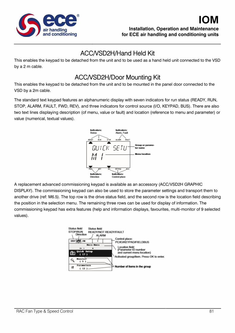
IOM
Installation, Operation and Maintenance
for ECE air handling and conditioning units
RAC Fan Type & Speed Control 81
ACC/VSD2H/Hand Held Kit
This enables the keypad to be detached from the unit and to be used as a hand held unit connected to the VSD
by a 2 m cable.
ACC/VSD2H/Door Mounting Kit
This enables the keypad to be detached from the unit and to be mounted in the panel door connected to the
VSD by a 2m cable.
The standard text keypad features an alphanumeric display with seven indicators for run status (READY, RUN,
STOP, ALARM, FAULT, FWD, REV), and three indicators for control source (I/O, KEYPAD, BUS). There are also
two text lines displaying description (of menu, value or fault) and location (reference to menu and parameter) or
value (numerical, textual values).
A replacement advanced commissioning keypad is available as an accessory (ACC/VSD2H GRAPHIC
DISPLAY). The commissioning keypad can also be used to store the parameter settings and transport them to
another drive (ref: M6.5). The top row is the drive status field, and the second row is the location field describing
the position in the selection menu. The remaining three rows can be used for display of information. The
commissioning keypad has extra features (help and information displays, favourites, multi-monitor of 9 selected
values).
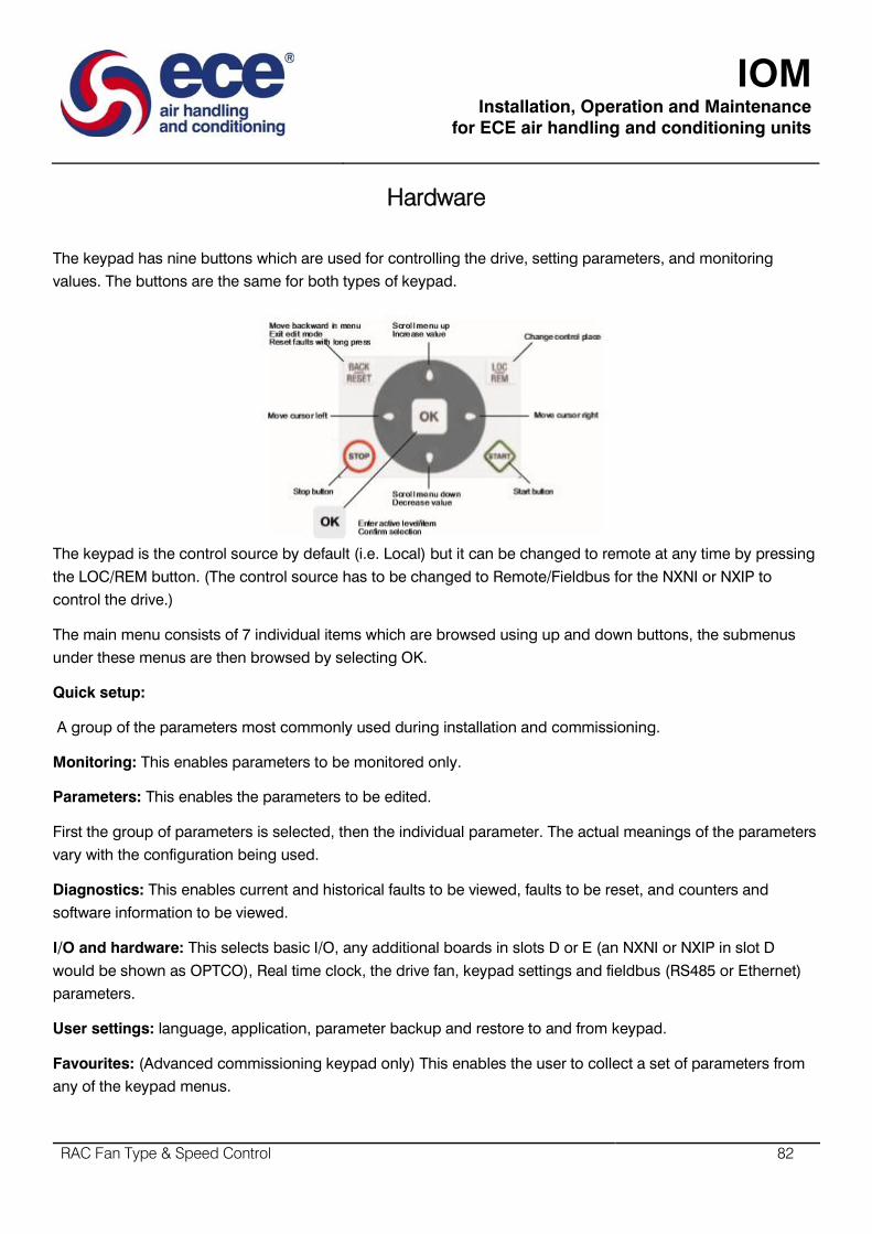
IOM
Installation, Operation and Maintenance
for ECE air handling and conditioning units
RAC Fan Type & Speed Control 82
Hardware
The keypad has nine buttons which are used for controlling the drive, setting parameters, and monitoring
values. The buttons are the same for both types of keypad.
The keypad is the control source by default (i.e. Local) but it can be changed to remote at any time by pressing
the LOC/REM button. (The control source has to be changed to Remote/Fieldbus for the NXNI or NXIP to
control the drive.)
The main menu consists of 7 individual items which are browsed using up and down buttons, the submenus
under these menus are then browsed by selecting OK.
Quick setup:
A group of the parameters most commonly used during installation and commissioning.
Monitoring: This enables parameters to be monitored only.
Parameters: This enables the parameters to be edited.
First the group of parameters is selected, then the individual parameter. The actual meanings of the parameters
vary with the configuration being used.
Diagnostics: This enables current and historical faults to be viewed, faults to be reset, and counters and
software information to be viewed.
I/O and hardware: This selects basic I/O, any additional boards in slots D or E (an NXNI or NXIP in slot D
would be shown as OPTCO), Real time clock, the drive fan, keypad settings and fieldbus (RS485 or Ethernet)
parameters.
User settings: language, application, parameter backup and restore to and from keypad.
Favourites: (Advanced commissioning keypad only) This enables the user to collect a set of parameters from
any of the keypad menus.

IOM
Installation, Operation and Maintenance
for ECE air handling and conditioning units
RAC Fan Type & Speed Control 83
Digital Input Isolation: The digital inputs (DI1 to DI6) can be isolated from ground by removing a link on the
control board as shown
Ethernet Connection: The Ethernet connection for BACnet over iIP or MODBUS TVP is situated under the
cover to the lefy of the control keypad, and the cable is run in a channel cut in the plastic flap. A shielded RJ45
connector should be used.
RS485 Connection: The RS485 connection for BACnet over MS/TP or MODBUS RTU uses terminals A and B
(A negative, B positive) in the basic I/O board terminal set. STP (Shielded Twisted Pair), type Belden cable 9841
or similar should be used. The termianto0r (see above DIP Sw 1) should only be switched on if the unit is at one
end of the bus.
Real Time Clock: The VSD2H has a real time clock with timer functions. The unit comes complete with a Real
Time Clock battery installed to maintain the time during power failure.
Integrated RFI-filter: The units have integrate RFI filters, enabling them to comply with EN61800-3 category C2
(suitable for public electricity networks such as buildings).
Integrated DC choke: The units are equipped with DC chokes to reduce harmoncs (THD), enabling them to
comply with EN61000-3-12.

IOM
Installation, Operation and Maintenance
for ECE air handling and conditioning units
RAC Fan Type & Speed Control 84
Integrated stress removal: stress removal and 360° grounding of power cables inside the unit with clamps. No
need for extra glands.
Quick Setup
On initial power up, the startup wizard will promopt for:
- Language
- Daylight saving
- Time, day, year
- Run startup Wizard (Y/N)
If yes:
- Process (pump or fan)
- Motor Nominal Speed (range 24 to 19200 rom)
- Motor Nominal Current (range depends on unit)
There are other mini-wizards that can be used for setting the following:
- PID: Three term control for motor or external device by way of I/O.
- Pump and Fan Cascade: Cascade control of several pumps or fans.
- Resonance Sweep: For elimination of possible resonance points in the system.
The quick setup menu, mentioned above, enables access to the parameters most commonly used during
installation and commissioning including access to the start-up, PID and pump and fan Cascade wizards.
Uninterruptible Operation and Energy Saving
Over temperature ride-through: Automatically adjusts switching frequency and/or speed of the motor to adapt
to unusual increase in ambient. The benefit of this is uninterruptible operation.
RTO – Ramp Time Optimizer: When problematic areas are identified in acceleration or declaration the drive
automatically expands the times needed for this to avoid mechanical stress to the system. The benefit of this is
the decreased mechanical stress to the system.
Trip free output switching: Ensures trip free operation when an output switch (e.g. safety switch) is operated
between the motor and the VSD. Truly intelligent and highly reliable function to ensure better functionality than
with any other VSD. The benefit of this will be Uninterruptible operation.
Energy Saving function (Flux Optimization): Flux Optimization automatically minimizes energy consumption.
The benefit will be a 5% increase in energy savings.
Configurable Auto Reset function: Auto restart function can be configured to make VSD restart automatically
once fault is addressed. The benefit of this is uninterruptible operation.

IOM
Installation, Operation and Maintenance
for ECE air handling and conditioning units
RAC Fan Type & Speed Control 85
VFD and Motor Control
Single Input Control: Analog signal rising edge can be used to start the device without additional start signal to
a digital input. The benefit of this is cost and time savings.
Flying start: Ability to get an already spinning fan under speed control. The benefits of this will be improved
performance, very important in clean room production.
Automatic torque boost function: Boosts initial voltage to start high inertia fans. The benefits of this is it avoids
tripping and enables smooth starts also to high inertia loads.
High Switching Frequency: The VSD2H is capable of providing the maximum power with high switching
frequency. The benefit of this is low audible noise from the motor.
Prohibit frequency: Overriding the critical frequencies to avoid resonance. Can be set with the help of
resonance sweep wizard. The benefit of this will be the elimination of resonance.
Maintenance counters/alarms: The drive can be programmed to notify on upcoming maintenance for the
system or the drive itself. The benefit of this will be the reliability.
Temperature-controlled fans: Fan stops operating when not needed. The benefits of this is less audible noise
from the VSD itself, and also energy savings.
Advanced HVAC Control
Time based control: With the help of the real time clock and calendar functionality the drive can be
programmed to perform functions based on time. The benefits of this will be cost savings and also flexibility.
Inbuilt PID Controller: Normal and Inverse Regulation, Delta P regulation with 2 standard pressure transmitters,
Feed forward control, less wiring since sensor normally close to inverter. The benefit of this would be the cost
saving and faster response to process closed loop.
Sleep Mode: Shutting down the motor, when no demand. The benefit of this will be energy savings.
Pressure loss compensation: For compensating e.g. wrongly placed sensor in the system. The benefit of this
will be a time and cost saving. Pump Soft Fill: Feature to prevent the overpressures when filling empty pipe
work. The benefit of this will be a longer lifetime of the system.
Fireoverride mode: Keeps fan/pump running in case of fire. This is a legal requirement.
Pump and Fan Cascade control with full auto-change: Controls total pumping system with several parallel
pumps by equally sharing the load. Also the master pump can be included in auto-change loop. The benefits of
this will be the longer lifetime of the system, also the cost savings will be a benefit.

IOM
Installation, Operation and Maintenance
for ECE air handling and conditioning units
RAC Fan Type & Speed Control 86
Software
Windows based PC utility tools are available for making the use of the Trend VSD2H as easy and convenient as
possible. The tools facilitate installation, commissioning and maintenance. The software is self-documenting
from its integral help file. The minimum requirement for using the software is a PC and a USB to RS485
interface cable (e.g. ACC/VSD2H/USB-PC/CABLE, 3 m), to be connected to the RS4785 terminal behind the
control panel.
Drive care PC tool: The drive Care tool is easy-to-use commissioning software for the control of the VSD2H. It
enables the following:
- Setting up parameters with the PC
- Saving settings to the PC
- Creating commissioning documentation
- Comparing parameters settings
- Monitoring view with graphics
- Diagnostics
- Controlling the drive from the PC.
This tool also includes the ‘Loader’ tool which enables the downloading of firmware or applications.
Note that the drive configuration can be loaded from one drive into the advanced commissioning keypad
(ACC/VSD2H/Graphic Display), and downloaded into another drive.

IOM
Installation, Operation and Maintenance
for ECE air handling and conditioning units
RAC Fan Type & Speed Control 87
SISO – Safety Isolators/Switch-disconnectors
Switches & Sensors
SISO – Safety Isolators/Switch-Disconnectors
Features
Electrical range 230V-690V, 1-3 phase, 50-60Hz, 0-63A
Enclosure IP66 Grey RAL 7035
Mechanically interlocked with 3 x padlock to ‘off’ apertures
Early breaker fitted to all units as standard. Three and six pole/wire versions available
Three and six pole/wire versions available
Two entries top and bottom 20/25A M20 40/63A M20/25
Stainless steel facia screws
Two earth continuity screws in each enclosure
Description
All fans and drives should have a correctly rated lockable Isolator switch instead in the power input circuit to
provide full electrical isolation. This is vital for safe installation, operation and maintenance.
Many modern drives also require an early break signal so that a graceful full power off can be achieved without
damage to sensitive electronics. Early break is included in all SISO Isolators. Isolators are provided with
mechanically interlocked IP56 standard.

IOM
Installation, Operation and Maintenance
for ECE air handling and conditioning units
RAC Fan Type & Speed Control 88
Range
IOM
Installation, Operation and Maintenance
for ECE air handling and conditioning units
AHU Commissioning 89
AHU Commissioning
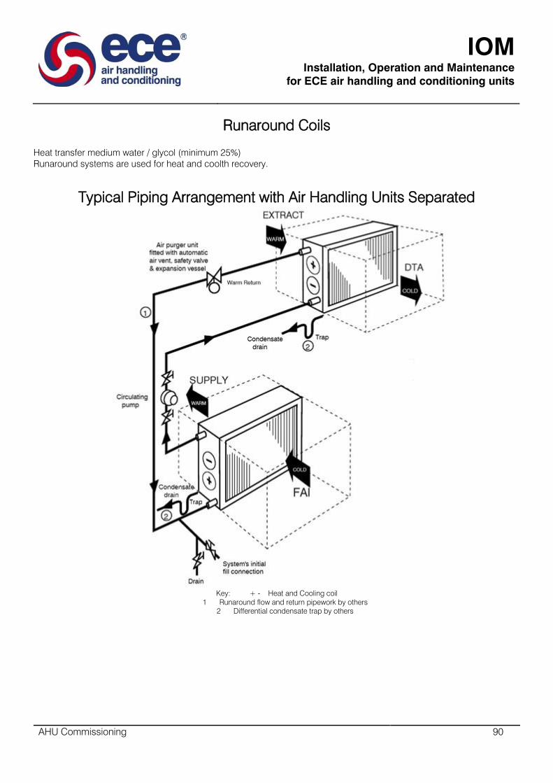
IOM
Installation, Operation and Maintenance
for ECE air handling and conditioning units
AHU Commissioning 90
Runaround Coils
Heat transfer medium water / glycol (minimum 25%)
Runaround systems are used for heat and coolth recovery.
Typical Piping Arrangement with Air Handling Units Separated
Key: + - Heat and Cooling coil
1 Runaround flow and return pipework by others
2 Differential condensate trap by others
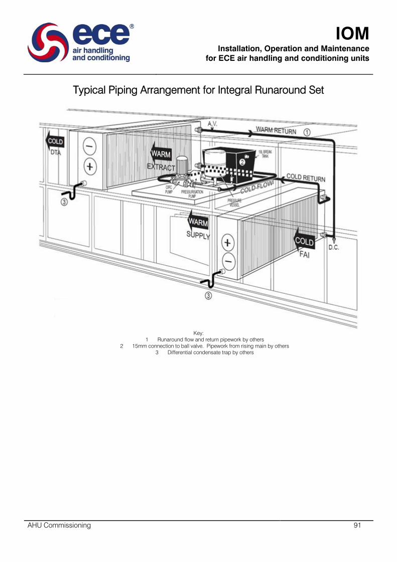
IOM
Installation, Operation and Maintenance
for ECE air handling and conditioning units
AHU Commissioning 91
Typical Piping Arrangement for Integral Runaround Set
Key:
1 Runaround flow and return pipework by others
2 15mm connection to ball valve. Pipework from rising main by others
3 Differential condensate trap by others

IOM
Installation, Operation and Maintenance
for ECE air handling and conditioning units
AHU Commissioning 92
Single Pressurisation Pump, Single Circulating Pump
Key:
1. Mains in - if fitted and not hand fill & top up during maintenance.
2. Break tank with ball valve, type A air gap and lid.
3. Pressurisation pump.
4. Expansion vessel controlling pressurisation pump.
5. Pressurisation pump, pressure control switch
6. Dian gauge 0 - 100 psi, 0 - 7bar
7. Pressure regulator
8. Dial gauge 0 - 4 bar red line at 3 bar.
9. 6 Bar safety valve (partly hidden)
10. Pressurized system expansion vessel
11. Circulation pump
12. Extract air runaround heat and coolth recovery coil with eliminators, drain pan & condensate drain connection drain trap & drain fitted on site.
13. Supply air runaround heat and coolth recovery coil with eliminators, drain pan & condensate drain connection drain trap & drain fitted on site.
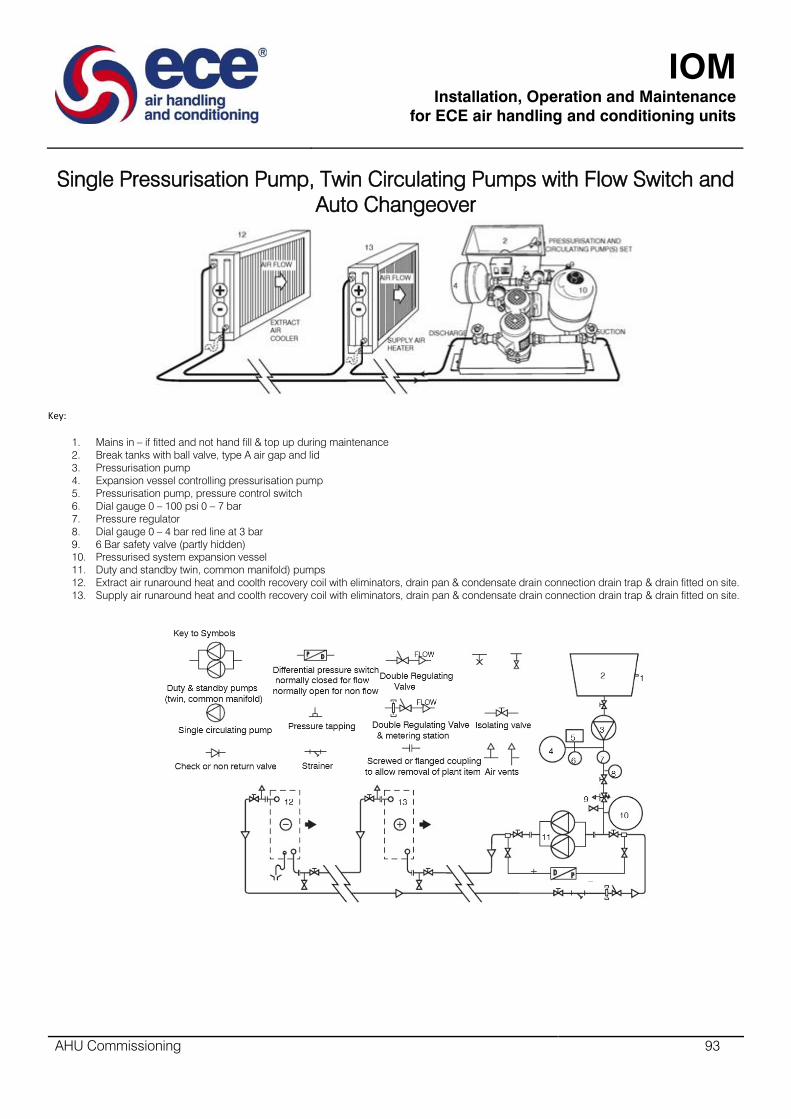
IOM
Installation, Operation and Maintenance
for ECE air handling and conditioning units
AHU Commissioning 93
Single Pressurisation Pump, Twin Circulating Pumps with Flow Switch and
Auto Changeover
Key:
1. Mains in – if fitted and not hand fill & top up during maintenance
2. Break tanks with ball valve, type A air gap and lid
3. Pressurisation pump
4. Expansion vessel controlling pressurisation pump
5. Pressurisation pump, pressure control switch
6. Dial gauge 0 – 100 psi 0 – 7 bar
7. Pressure regulator
8. Dial gauge 0 – 4 bar red line at 3 bar
9. 6 Bar safety valve (partly hidden)
10. Pressurised system expansion vessel
11. Duty and standby twin, common manifold) pumps
12. Extract air runaround heat and coolth recovery coil with eliminators, drain pan & condensate drain connection drain trap & drain fitted on site.
13. Supply air runaround heat and coolth recovery coil with eliminators, drain pan & condensate drain connection drain trap & drain fitted on site.
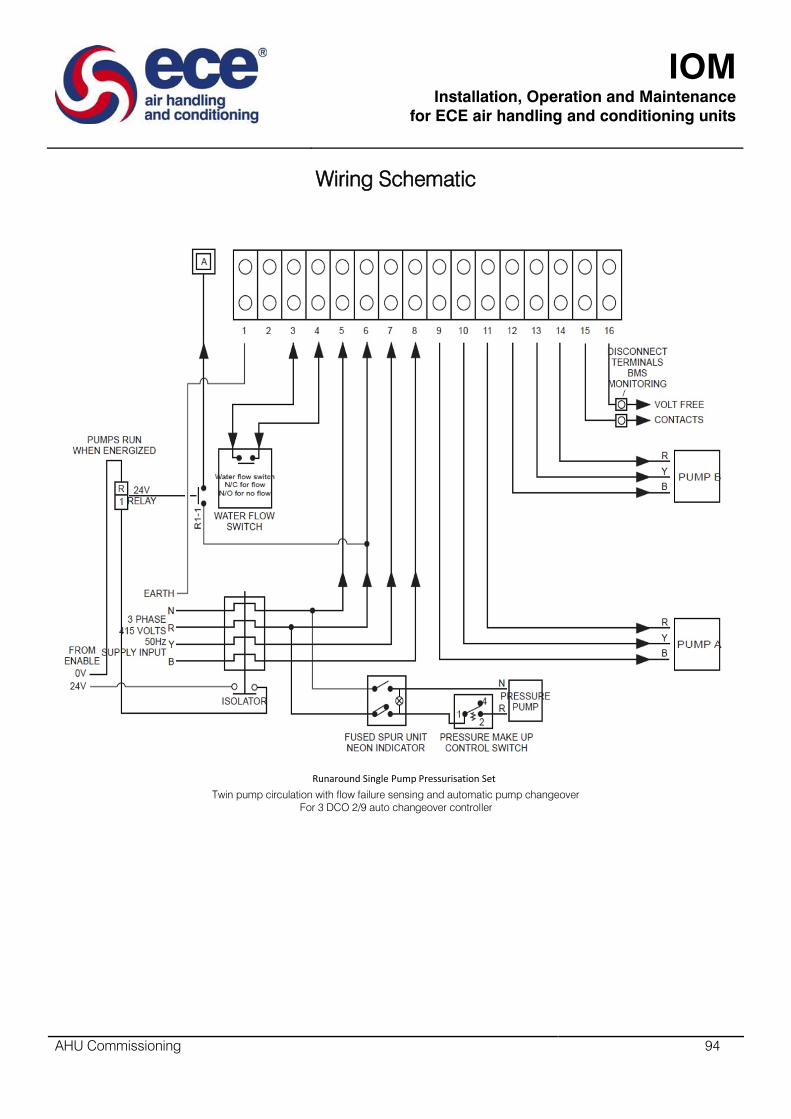
IOM
Installation, Operation and Maintenance
for ECE air handling and conditioning units
AHU Commissioning 94
Wiring Schematic
Runaround Single Pump Pressurisation Set
Twin pump circulation with flow failure sensing and automatic pump changeover
For 3 DCO 2/9 auto changeover controller
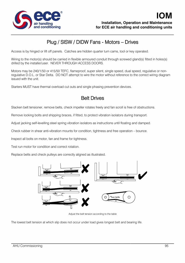
IOM
Installation, Operation and Maintenance
for ECE air handling and conditioning units
AHU Commissioning 95
Plug / SISW / DIDW Fans - Motors – Drives
Access is by hinged or lift off panels. Catches are hidden quarter turn cams, tool or key operated.
Wiring to the motor(s) should be carried in flexible armoured conduit through screwed gland(s) fitted in holes(s)
drilled by the installer/user. NEVER THROUGH ACCESS DOORS.
Motors may be 240/1/50 or 415/50 TEFC, flameproof, super silent, single speed, dual speed, regulative or non-
regulative D.O.L. or Star Delta. DO NOT attempt to wire the motor without reference to the correct wiring diagram
issued with the unit.
Starters MUST have thermal overload cut outs and single phasing prevention devices.
Belt Drives
Slacken belt tensioner, remove belts, check impeller rotates freely and fan scroll is free of obstructions.
Remove locking bolts and shipping braces, if fitted, to protect vibration isolators during transport.
Adjust jacking self-levelling steel spring vibration isolators as instructions until floating and damped.
Check rubber in shear anti-vibration mounts for condition, tightness and free operation – bounce.
Inspect all bolts on motor, fan and frame for tightness.
Test run motor for condition and correct rotation.
Replace belts and check pulleys are correctly aligned as illustrated.
Adjust the belt tension according to the table
The lowest belt tension at which slip does not occur under load gives longest belt and bearing life.

IOM
Installation, Operation and Maintenance
for ECE air handling and conditioning units
AHU Commissioning 96
Belt Section SPZ SPZ SPA SPA SPB SPB SPC SPC
Small pulley diameter Min 67 100 100 140 160 236 224 375
Max 95 140 132 200 224 315 355 560
KG force for 16mm* defl’n / metre span Min 1.0 1.5 2.0 2.8 3.5 5.1 6.1 9.2
Max 1.5 2.0 2.7 3.5 5.1 6.6 9.2 12.2
With all access panels in place, components installed and the cutting system complete, connected and
commissioned, check that measured full load current is less than motor nameplate full load current. Check that
starter overload setting is correct and that single phasing protection is functioning. If any problems occur refer to
Fault Finding Section of this manual.
The complete ductwork system should be proportioned to CIBSE - ASHRAE recommended procedure.
The Volume should be measured and if outside CIBSE recommendations or specified tolerances then;
Installer / commissioning engineer should submit full commissioning data to ECE.
ECE will calculate new fan speed required to achieve design volume and recommend pulley(s) & belt(s) sizes
required to achieve new fan speed.
Installer/commissioning engineer should then:
Purchase new pulleys and belts available locally from nationwide stockists
Change pulley(s) and belt(s) on site
Re-measure volume
Recheck proportion and volumes to air terminal devices
ECE site operatives are available for changing belts and pulleys on site at extra cost if required.
“Rotating standby motors generate electricity even when isolated from the mains. If the motor is
being rotated by the fan do not touch the terminals even if the motor is isolated”
The most common cause of incorrect fan volume is over estimation of system resistance. Please check this before
contacting ECE.
Unless specified otherwise fans are belted to give specified volume with clean filters.
Where the specification calls for design volume with dirty filters we recommend the incorporation of pressure
activated constant volume control since selection of the fan(s) at final system resistance could result in
considerable excess volume initially.
Excess volume can cause:
Coil off temperature, hence room supply air temperature, hence room temperature not being achieved
Water carryover and flooding
Motor overload and burnout
Increased fan noise levels
Turbulence and excitation of duct walls resulting in noise and vibration problems
Noise regeneration at changes of direction, volume control dampers and air terminal devices
Reduced filter life
Gross under volume can cause coil sweating, freezing and motor burn out.
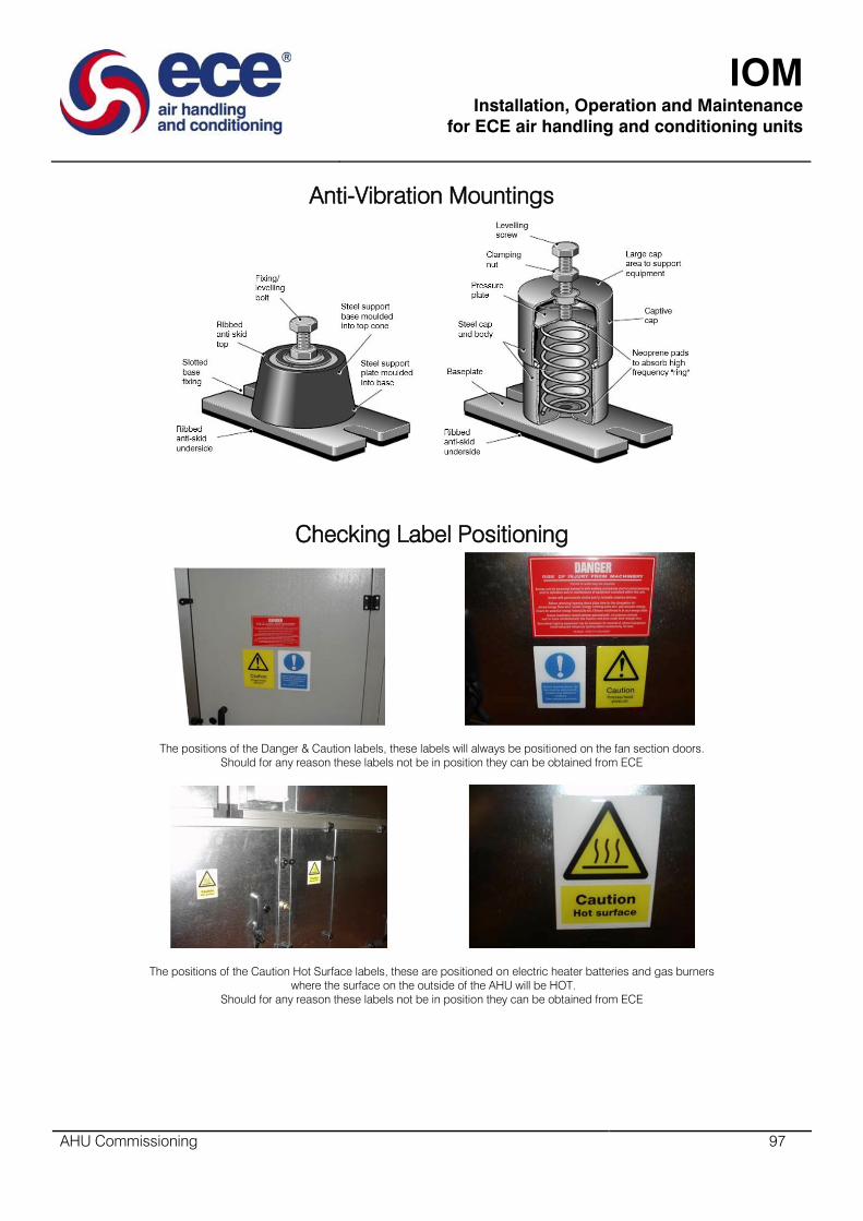
IOM
Installation, Operation and Maintenance
for ECE air handling and conditioning units
AHU Commissioning 97
Anti-Vibration Mountings
Checking Label Positioning
The positions of the Danger & Caution labels, these labels will always be positioned on the fan section doors.
Should for any reason these labels not be in position they can be obtained from ECE
The positions of the Caution Hot Surface labels, these are positioned on electric heater batteries and gas burners
where the surface on the outside of the AHU will be HOT.
Should for any reason these labels not be in position they can be obtained from ECE
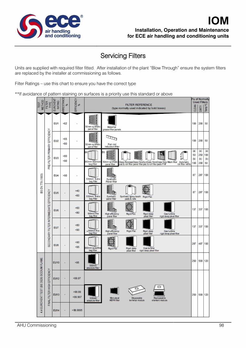
IOM
Installation, Operation and Maintenance
for ECE air handling and conditioning units
AHU Commissioning 98
Servicing Filters
Units are supplied with required filter fitted. After installation of the plant “Blow Through” ensure the system filters
are replaced by the installer at commissioning as follows.
Filter Ratings – use this chart to ensure you have the correct type
**If avoidance of pattern staining on surfaces is a priority use this standard or above
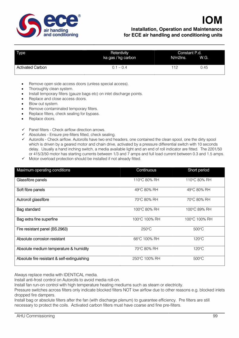
IOM
Installation, Operation and Maintenance
for ECE air handling and conditioning units
AHU Commissioning 99
Type Retentivity
ka gas / kg carbon
Constant P.d.
N/m2ins. W.G.
Activated Carbon
0.1 – 0.4 112 0.45
Remove open side access doors (unless special access).
Thoroughly clean system.
Install temporary filters (gauze bags etc) on inlet discharge points.
Replace and close access doors.
Blow out system.
Remove contaminated temporary filters.
Replace filters, check sealing for bypass.
Replace doors.
Panel filters - Check airflow direction arrows.
Absolutes - Ensure pre-filters fitted, check sealing.
Autorolls - Check airflow. Autorolls have two end headers, one contained the clean spool, one the dirty spool
which is driven by a geared motor and chain drive, activated by a pressure differential switch with 10 seconds
delay. Usually a hand inching switch, a media available light and an end of roll indicator are fitted. The 2201/50
or 415/3/50 motor has starting currents between 1/3 and 7 amps and full load current between 0.3 and 1.5 amps.
Motor overload protection should be installed if not already fitted.
Maximum operating conditions Continuous
Short period
Glassfibre panels 110oC 80% RH
110oC 80% RH
Soft fibre panels 49oC 80% RH
49oC 80% RH
Autroroll glassfibre 70oC 80% RH
70oC 80% RH
Bag standard 100oC 80% RH
100oC 89% RH
Bag extra fine superfine 100oC 100% RH
100oC 100% RH
Fire resistant panel (BS.2963) 250oC
500oC
Absolute corrosion resistant 66oC 100% RH
120oC
Absolute medium temperature & humidity 70oC 80% RH
120oC
Absolute fire resistant & self-extinguishing 250oC 100% RH
500oC
Always replace media with IDENTICAL media.
Install anti-frost control on Autorolls to avoid media roll-on.
Install fan run-on control with high temperature heating mediums such as steam or electricity.
Pressure switches across filters only indicate blocked filters NOT low airflow due to other reasons e.g. blocked inlets
dropped fire dampers.
Install bag or absolute filters after the fan (with discharge plenum) to guarantee efficiency. Pre filters are still
necessary to protect the coils. Activated carbon filters must have coarse and fine pre-filters.
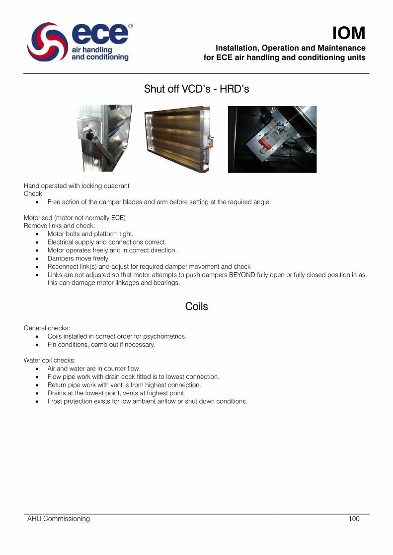
IOM
Installation, Operation and Maintenance
for ECE air handling and conditioning units
AHU Commissioning 100
Shut off VCD’s - HRD’s
Hand operated with locking quadrant
Check:
Free action of the damper blades and arm before setting at the required angle.
Motorised (motor not normally ECE)
Remove links and check:
Motor bolts and platform tight.
Electrical supply and connections correct.
Motor operates freely and in correct direction.
Dampers move freely.
Reconnect link(s) and adjust for required damper movement and check
Links are not adjusted so that motor attempts to push dampers BEYOND fully open or fully closed position in as
this can damage motor linkages and bearings.
Coils
General checks:
Coils installed in correct order for psychometrics.
Fin conditions, comb out if necessary.
Water coil checks:
Air and water are in counter flow.
Flow pipe work with drain cock fitted is to lowest connection.
Return pipe work with vent is from highest connection.
Drains at the lowest point, vents at highest point.
Frost protection exists for low ambient airflow or shut down conditions.

IOM
Installation, Operation and Maintenance
for ECE air handling and conditioning units
AHU Commissioning 101
Coil Connections
Ensure connections to coils are bottom inlet and top outlet, this arrangement ensures thermal siphoning aids flow.
Performance will be limited it these connections are made the wrong way.
Refer to following section for full details on coil and condensate drain connections

IOM
Installation, Operation and Maintenance
for ECE air handling and conditioning units
AHU Commissioning 102
Setting Water Flow through Coils
Open all manual valves fully – including the bypass valve on the three port control valves diverting port.
Ensure that the three port control is set to pass 100% flow through the air handling unit coil.
With the aid of a screwdriver open the two small inbuilt valves either side of the flow indicator window on the main
commissioning unit. The main commissioning unit is sited in the main return pipe (these small valves allow water to
pass through the indicator window to enable flow rate to be observed.
Set the flow rate through the coil by rotating the larger valve on the main commissioning unit to restrict the water
flow until the desired flow rate is indicated in the window. Once this valve has been set DO NOT adjust it again.
Move the three port control valve into the 100% bypass position.
Slowly close the secondary commissioning valve (sited on the three port control valves bypass port) at the same
time observe the flow rate being indicated in the window of the main commissioning valve. Continue closing this
valve until the same flow rate reading as before is obtained.
Conclude by closing the two small integral valves wither side of the indicator window on the main commissioning
valve.
The system is now balanced.

IOM
Installation, Operation and Maintenance
for ECE air handling and conditioning units
AHU Commissioning 103
Coil Condensate Drains
Draw Through Units and Blow Through Units with negative pressure (depression at trap)
10pa difference in pressure = 1mm difference in water level
i.e. 190mm = 1900pa depression -- 235mm = 2350pa depression

IOM
Installation, Operation and Maintenance
for ECE air handling and conditioning units
AHU Commissioning 104
Blow through units with positive pressure at trap
10pa difference in pressure = 1mm difference in water level
i.e. 190mm = 1900pa depression -- 235mm = 2350pa depression
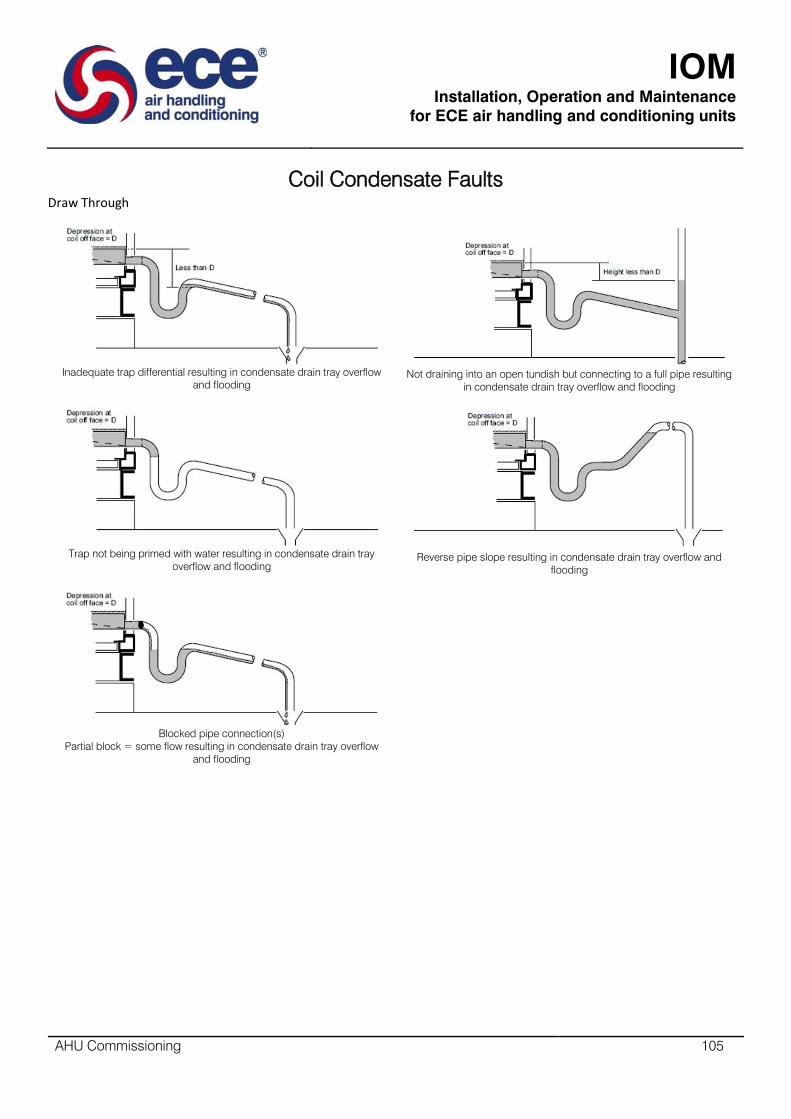
IOM
Installation, Operation and Maintenance
for ECE air handling and conditioning units
AHU Commissioning 105
Coil Condensate Faults
Draw Through
Inadequate trap differential resulting in condensate drain tray overflow
and flooding
Not draining into an open tundish but connecting to a full pipe resulting
in condensate drain tray overflow and flooding
Trap not being primed with water resulting in condensate drain tray
overflow and flooding
Reverse pipe slope resulting in condensate drain tray overflow and
flooding
Blocked pipe connection(s)
Partial block = some flow resulting in condensate drain tray overflow
and flooding

IOM
Installation, Operation and Maintenance
for ECE air handling and conditioning units
AHU Commissioning 106
Blow Through
Inadequate trap differential resulting in priming water blow-out “splutter”
and air leakage
Not draining into an open tundish but connecting to a full pipe resulting
in condensate drain tray overflow and flooding
Correct trap but not primed with water resulting in condensate blow-out
“splutter” and air leakage
Reverse pipe slope resulting in condensate drain tray overflow and
flooding
Partially of fully blocked pipe connection(s) resistance through blockage
greater than P resulting in drain tray overflow and flooding.
Partial block = some flow

IOM
Installation, Operation and Maintenance
for ECE air handling and conditioning units
AHU Commissioning 107
Draw through coils with condensate pump
Pump sump primed with water
Fan off
Coil off
No difference in water levels
Fan starts and creates depression at
coil
Priming water in pipe rises 1 𝑥 𝐷
Priming water in sump falls
1 𝑥 𝐷 𝑥 𝐴𝑟𝑒𝑎 𝑜𝑓 𝑝𝑖𝑝𝑒
𝐴𝑟𝑒𝑎 𝑜𝑓 𝑠𝑢𝑚𝑝
Coil is still off so no condensate is
flowing
Fan still running and creating
depression at coil
Coil operating, condensate flowing
Water level in pipe rises
Water level in sump also rises until
HLFS operates
Pump starts
Pump runs
Water levels falls until LLFS breaks
Pump stops
H = depression at off face of cooling coil + difference in level between HLFS operating and pipe openings
10pa difference is pressure = 1mm difference in water level
i.e. 1900pa depression – 235mm = 2350pa depression
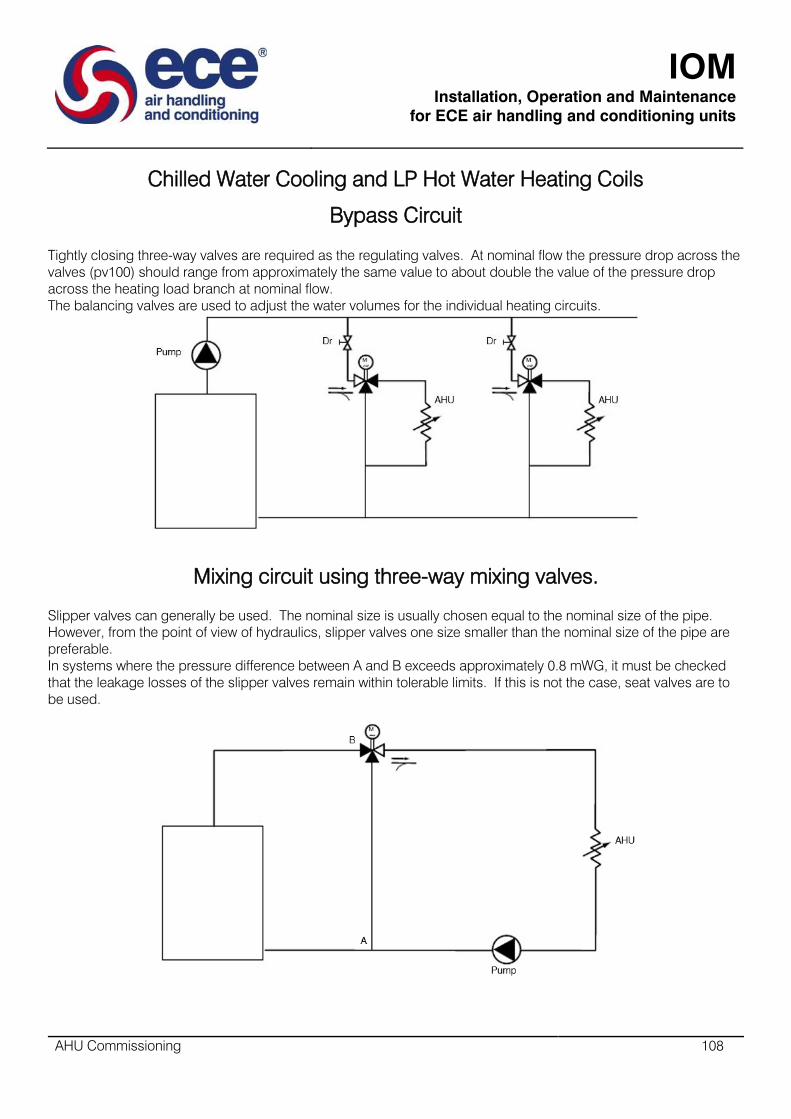
IOM
Installation, Operation and Maintenance
for ECE air handling and conditioning units
AHU Commissioning 108
Chilled Water Cooling and LP Hot Water Heating Coils
Bypass Circuit
Tightly closing three-way valves are required as the regulating valves. At nominal flow the pressure drop across the
valves (pv100) should range from approximately the same value to about double the value of the pressure drop
across the heating load branch at nominal flow.
The balancing valves are used to adjust the water volumes for the individual heating circuits.
Mixing circuit using three-way mixing valves.
Slipper valves can generally be used. The nominal size is usually chosen equal to the nominal size of the pipe.
However, from the point of view of hydraulics, slipper valves one size smaller than the nominal size of the pipe are
preferable.
In systems where the pressure difference between A and B exceeds approximately 0.8 mWG, it must be checked
that the leakage losses of the slipper valves remain within tolerable limits. If this is not the case, seat valves are to
be used.

IOM
Installation, Operation and Maintenance
for ECE air handling and conditioning units
AHU Commissioning 109
Chilled Water Cooling Coils
Coils are normally of open header box construction (but may have split end covers supplied to order) are
completely self-supporting and designed to be fitted directly between or within the sections of the air handling unit.
When split cover plates are supplied these should be removed prior to connections being made, then replaced.
Great care should be taken when tightening connections to avoid damage to the coil. The space between the pipe
work and cover plates should be sealed with a grommet or similar.
A correctly sized thermostatic expansion valve with external equalising connection must be fitted.
Run the liquid refrigerant line to the TEV which should be fitted to the liquid distributor, feeding the individual circuits
of the evaporator coil.
An adequately sized suction line should be run from the suction head to the compressor.
The valve equalising line should be run to the suction line on the compressor side of the valve sensitive phial which
should be placed on top of the suction line periphery and secured with a special slip.
A suction liquid heat exchanger should be used to improve the performance of the expansion valve and utilise the
complete coil surface.
If your unit is built to HTM standard each coil will come with a removable drain tray. A screw connection joins the
tray to the drain line, which can be detached so the tray can be removed and washed down.
A correctly sized sloping drain line with a cleanable “U” bend water trap terminating at an open drain or tundish
should be run from each drain connection.

IOM
Installation, Operation and Maintenance
for ECE air handling and conditioning units
AHU Commissioning 110
Hot Water Heating Coils
Coils are normally of open header box construction (but may have split end covers supplied to order) are
completely self-supporting and designed to be fitted directly between or within the sections of the air handling unit.
When split cover plates are supplied these should be removed prior to connections being made, then replaced.
Great care should be taken when tightening connections to avoid damage to the coil. The space between the pipe
work and cover plates should be sealed with a grommet or similar.
A correctly sized sloping drain line with a cleanable “U” bend water trap terminating at an open drain or tundish
should be run from each drain connection.
Heater coil automatic control valves should be wired into the fan starter circuit so that valve motors close when fan
is stopped. This prevents temperature build up within the unit and possible harm to motor windings, particularly
important with high pressure hot water or steam coils.
A typical piping arrangement for hot water heating coil
A typical schematic for hot water heating coil

IOM
Installation, Operation and Maintenance
for ECE air handling and conditioning units
AHU Commissioning 111
Steam Coils
Coils are normally of open header box construction (but may have split end covers supplied to order) are self-
supporting and designed to be fitted directly between or within the sections of the air handling unit.
When split cover plates are supplied these should be removed prior to connections being made, then replaced.
The space between the pipe work and cover plates should be sealed with a grommet or similar.
Check:
Supply is under 100 PSIG dry.
Supply is free of air and connected to the top coil connection.
Connecting pipe work is not supported by coil.
Expansion allowance made for coil tubes.
Connections are free from stress and are properly pitched and drained (to avoid water hammer).
Condensate connections to the steam trap are the same size as the coil outlet.
Condensate in the main is independently trapped on a coil bypass.
The steam trap is sized on 3 times the design flow.
Float or bucket type traps should be carefully selected to suit the steam pressures and temperatures with
thermostatic air relief traps on low pressure systems and continuous venting petcocks on medium and high
pressure systems.
Multiple or banks of coils must be individually trapped to meet the demands of the varying capacities and
pressures on each section.
Selection of control valves must be based on the steam load and not the size of the steam coil supply
connection.
Automatic steam control valves are suitable where the condensate is returned to atmospheric pressure or under
vacuum.
They are not recommended on systems where pressure is maintained on the return lines.
Steam pressure in the coil is not used for lifting condensate.
If coil is near filter ensure fan runs on after steam supply is cut off (2 minutes).
Note:
Over tightening connections damages coils.
Initial rapid heat build-up causes damage to coils and associated pipe work, valve opening must be gradual.
Check for leaks on initial start-up and after a short period of operation.

IOM
Installation, Operation and Maintenance
for ECE air handling and conditioning units
AHU Commissioning 112
A typical piping arrangement for low pressure steam or vacuum system
A typical piping arrangement for high pressure steam system
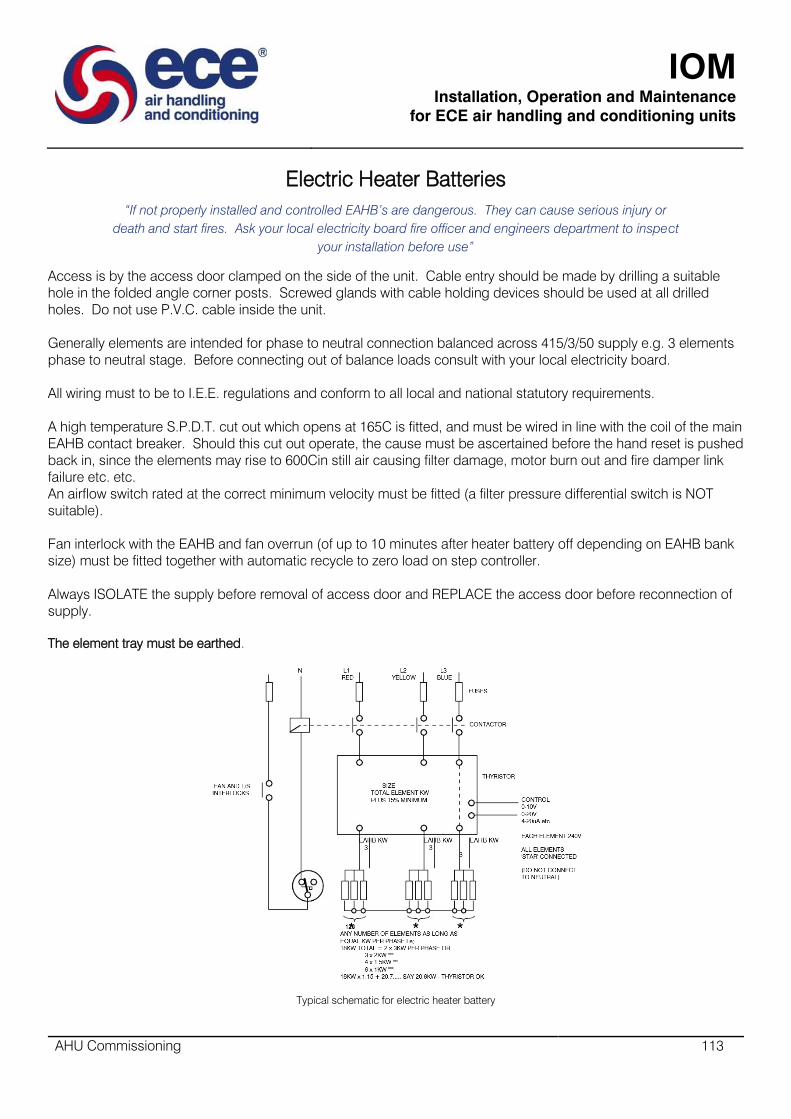
IOM
Installation, Operation and Maintenance
for ECE air handling and conditioning units
AHU Commissioning 113
Electric Heater Batteries
“If not properly installed and controlled EAHB’s are dangerous. They can cause serious injury or
death and start fires. Ask your local electricity board fire officer and engineers department to inspect
your installation before use”
Access is by the access door clamped on the side of the unit. Cable entry should be made by drilling a suitable
hole in the folded angle corner posts. Screwed glands with cable holding devices should be used at all drilled
holes. Do not use P.V.C. cable inside the unit.
Generally elements are intended for phase to neutral connection balanced across 415/3/50 supply e.g. 3 elements
phase to neutral stage. Before connecting out of balance loads consult with your local electricity board.
All wiring must to be to I.E.E. regulations and conform to all local and national statutory requirements.
A high temperature S.P.D.T. cut out which opens at 165C is fitted, and must be wired in line with the coil of the main
EAHB contact breaker. Should this cut out operate, the cause must be ascertained before the hand reset is pushed
back in, since the elements may rise to 600Cin still air causing filter damage, motor burn out and fire damper link
failure etc. etc.
An airflow switch rated at the correct minimum velocity must be fitted (a filter pressure differential switch is NOT
suitable).
Fan interlock with the EAHB and fan overrun (of up to 10 minutes after heater battery off depending on EAHB bank
size) must be fitted together with automatic recycle to zero load on step controller.
Always ISOLATE the supply before removal of access door and REPLACE the access door before reconnection of
supply.
The element tray must be earthed.
Typical schematic for electric heater battery
IOM
Installation, Operation and Maintenance
for ECE air handling and conditioning units
AHU Commissioning 114
Gas Fired Heaters
Safety Notes:
Commissioning is recommended by our operatives, in any event gas piping, flue, electricity supply and controls
should comply with gas safety, gas region, local authority, fire authority and insurance company regulations.
Do not locate in presence of chlorinated or corrosive vapours, in areas of high risk i.e. cellulose spraying, near
combustible materials or where atmospheric depression i.e. an area with extract fan or system, could cause gas
reverse flow into area.
Ensure 24” minimum clearance all round this section.
Do not obstruct or modify build in diverter.
Except for servicing never switch off the power supply to the unit.
Internal Safety controls comprise:
Main gas valve closure if pilot light out
Fan on delay unit burner warm.
Gas off on overheat.
Fan off delay until burner cool.
External services required:
Natural gas supply
Combustion air supply
Combustion gas flue
Electricity supply for controls
Electricity supply for motive power
Flue gas discharge:
Flue gas leaving the top spigot at 260deg C should be vented to atmosphere using a gas board approved flue
terminal via a properly sized, individual, VERTICAL, natural draught flue rising 1.8m min.
Unavoidable horizontal runs (max 3m) should slope 65mm in 300mm and have final verticals riser of 1.5 times
the horizontal run. If these conditions cannot be met then factory installed fan assistance should be considered.
If condensation is possible it should be avoided by using double skinned flue with special joiner and spigot
(consult your local G.A.). If condensation still occurs a non-corrosive 22mm (min) drain should be fitted.
External controls required are:
On/off switching (time clock start/stop, thermostat controlling burner)
Normal electrical controls (fan motor starter, contactors and overload isolators etc.)
Wiring:
Refer to appropriate diagram supplied with unit and not the following:
Switching must be by individual 24V controls to each unit and should incorporate a 24V thermostat, switch and
time clock in series.
Never apply higher voltages (240V supply to motor of time clock must be separate).
Power into the control box can only be 220V l phase 50c/s.
Single phase fan motors up to 0.5kw (0.7 h.p.) can be connected via thermal overloads direct to the box.
Over 0.5kW single phase and all 3 phase motors must have separate electrical supplies controlled from the box
via a 240V contactor relay and should be protected by thermal overloads.
IOM
Installation, Operation and Maintenance
for ECE air handling and conditioning units
AHU Commissioning 115
Inspection prior to initial start up
Gas shut off valve closed:-
Check all electrical functions - fan motors, room thermostat and gas control set/automatic gas safety system.
Check correct rotation of fans.
Gas shut off valve open:-
Carefully vent and check all gas lines for leakage by soapy water testing.
Close gas shut off valve.
Initial start up
Switch on main switch
Supply air discharge(s) open
Room thermostat “off” lowest setting
Time switch at “on” period
Turn on main gas
The unit will now start
Refer to user manual supplied with gas heater unit for details start up procedure.

IOM
Installation, Operation and Maintenance
for ECE air handling and conditioning units
AHU Commissioning 116
Electronic Steam Humidifiers
Humidifiers supplied for use with ECE units are electrode boilers which operate at atmospheric pressure and utilise
standard water supplies provided the local regulations regarding connection of this type of equipment are
observed. If local regulations call for the use of a break tank to feed the unit, the speed at which the humidifier
cylinder fills with be determined by the head pressure available. The size of tank, its height and the size of its
connecting pipe work must be chosen carefully to ensure the unit always receives an adequate water supply.
A built in flow regulator compensates for pressure fluctuations.
Water - drain connections
Standard unit inlets are supplied with 15mm brass compression fittings.
Drains are brass couplings of l.5” BSP male thread and 1.25” BSP female thread sizes.
Power Supply
Connect using conduit entry glands through appropriate knockouts in casing.
Wiring should comply with the relevant local regulations using appropriately sized circuit breakers.
Control connection
When step control or modulation is required, the boiler, services and controls are mounted in a cabinet which
may be fixed to the side of the air conditioning unit or to an adjacent vertical surface BELOW the sparge pipe
level.
When on-off switching only is required the boiler and its services may be mounted inside the air conditioning unit
with the control panel remote.
Start up
Close electrical panel
Turn on water supply to humidifier
Close circuit breaker feeding power supply to humidifier
Put run/drain switch into the “RUN” position
Put on/off switch into the “ON” position
Humidifier will now operate to the demands of the control circuit.
Operation of typical electronic steam humidifier

IOM
Installation, Operation and Maintenance
for ECE air handling and conditioning units
AHU Commissioning 117
Operation of typical electronic steam humidifier

IOM
Installation, Operation and Maintenance
for ECE air handling and conditioning units
AHU Commissioning 118
GMEC Commissioning
Safety checking
Check that the impeller rotates freely.
Make sure that there are no foreign objects in the fan or in the Air Handling Unit.
Also check that there is no unusual noise in the fan or motor.
Check that the installation work has been carried out in accordance with the relevant regulations.
Cables and air flow measurement tubes must be attached so that they do not touch the impeller.
All necessary protective devices must be installed.
The fan may only be commissioned after all proper procedures have been followed and all necessary
inspections have been carried out.
Test run
Briefly switch on the power supply to the motor to check whether the fan impeller rotates in the correct
direction. If the impeller I rotating in the correct direction, the fan may be switched on.
Check that no abnormal mechanical sound and no surging occur.
GPEB Commissioning
Rotate the shaft and check that the impeller can move freely. Make sure that there are no foreign objects in the
fan or in the ducting. Also check that there is no unusual noise in the fan. Check that the installation work has
been carried out in accordance with the relevant regulations.
All necessary protective devices must be installed.
The fan may only be commissioned after all proper procedures have been followed and all necessary
inspections have been carried out.
Test Run
Briefly switch on the power supply to the motor to check whether the fan impeller rotates in the correct
direction. If the impeller is rotating in the correct direction, the fan may be switched on. Check that no abnormal
mechanical sound and no surging occurs.
IOM
Installation, Operation and Maintenance
for ECE air handling and conditioning units
AHU Commissioning 119
GMEB Commissioning
Safety Checking
Rotate the shaft and check that the impeller can move freely.
Make sure that there are no longer foreign objects in the fan or in the ducting.
Also check that there is no unusual noise in the fan.
Check that the installation work has been carried out in accordance with the relevant regulations.
All necessary protective devices must be installed.
The fan may only be commissioned after all proper procedures have been followed and all necessary
inspections have been carried out.
Test Run
Briefly switch on the power supply to the motor to check whether the fan impeller rotates in the correct
direction. If the impeller is rotating in the correct direction, the fan may be switched on. Check that no abnormal
mechanical sound and no surging occurs.

IOM
Installation, Operation and Maintenance
for ECE air handling and conditioning units
Maintenance 120
Maintenance
IOM
Installation, Operation and Maintenance
for ECE air handling and conditioning units
Maintenance 121
Plug Fan Air flow measurement device
The airflow sensor is used for measuring the airflow of the plug fans. The method is based on differential
pressure. The pressure is measured at a specific point in the inlet cone and the reference pressure is measured
upstream of the inlet cone. The air flow sensor is supplied factory mounted in the inlet cone.
Disposal of the product
Used product shall be disposed or recycled according to the local laws and regulations.
Before Maintenance
Switch off the power supply to the fan at the safety switch and wait until the impeller is fully stopped.
“There is a risk of electric shock on PM-motors if the impeller is rotating. Ensure that the impeller is surely still
before and during the maintenance work.
Inspection
The fan is to be inspected at least once a year.
Checking the motor bearings
The motors are meant to be operated in dry or humid air at a normal ambient temperature. The motor bearings
have to be lubricated in accordance with the instructions that accompany the motor. Bearings are to be
replaced in accordance with the motor manufacturers instructions.
Impeller
The maximum permissible vibration level measured from the motor bearing is 4.5mm/s RMS. The impeller can
be cleaned by using a vacuum cleaner, compressed air or by brushing. If the impeller is coated with greasy dirt
it can be washed with a detergent or a solvent.
The cleaning is to be done at least once a year Badly tarnished impeller will result in lower efficiency of the fan
and increases energy consumption.
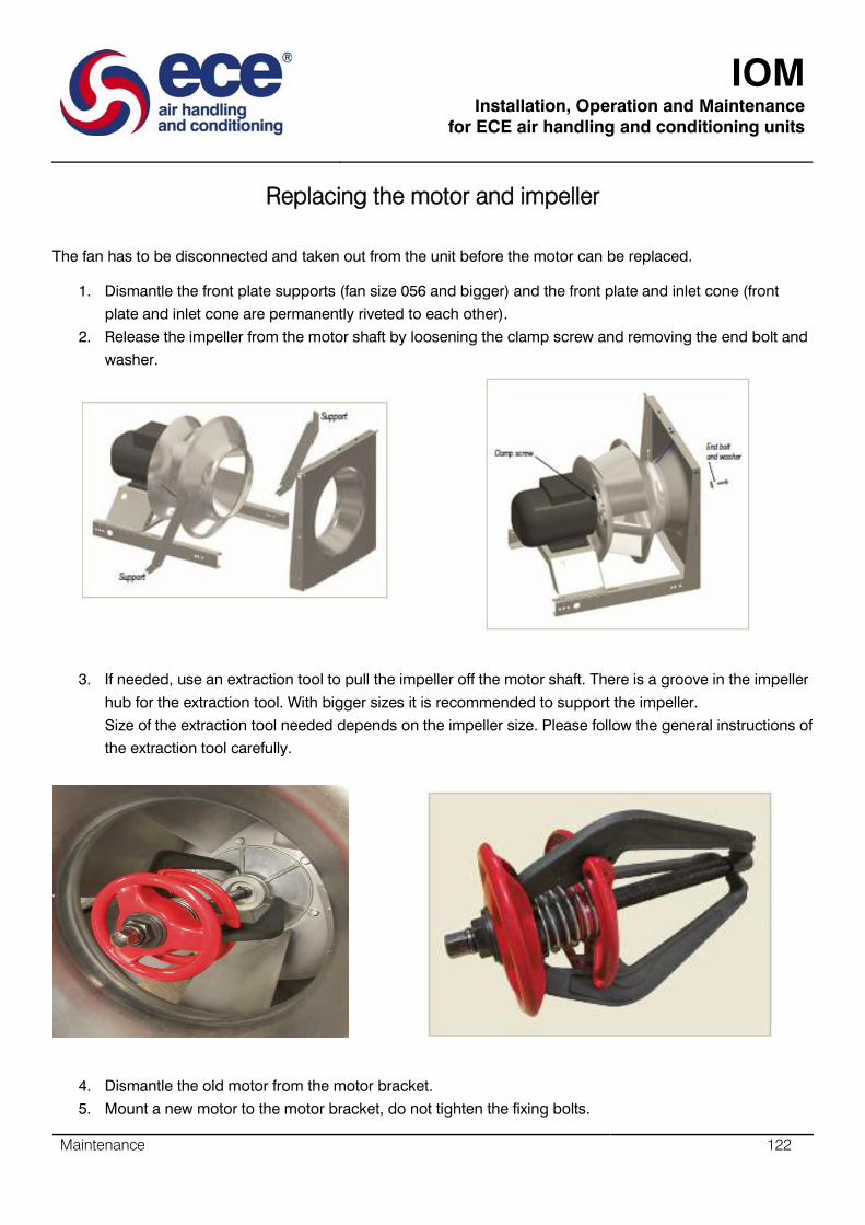
IOM
Installation, Operation and Maintenance
for ECE air handling and conditioning units
Maintenance 122
Replacing the motor and impeller
The fan has to be disconnected and taken out from the unit before the motor can be replaced.
1. Dismantle the front plate supports (fan size 056 and bigger) and the front plate and inlet cone (front
plate and inlet cone are permanently riveted to each other).
2. Release the impeller from the motor shaft by loosening the clamp screw and removing the end bolt and
washer.
3. If needed, use an extraction tool to pull the impeller off the motor shaft. There is a groove in the impeller
hub for the extraction tool. With bigger sizes it is recommended to support the impeller.
Size of the extraction tool needed depends on the impeller size. Please follow the general instructions of
the extraction tool carefully.
4. Dismantle the old motor from the motor bracket.
5. Mount a new motor to the motor bracket, do not tighten the fixing bolts.

IOM
Installation, Operation and Maintenance
for ECE air handling and conditioning units
Maintenance 123
6. Clean the motor shaft and the impeller hub hole. Use of lubrication is recommended.
7. Mount the impeller on the motor shaft.
8. Mark the needed overlap to the inlet cone, see the below illustration and table.
9. Mount the front plate and inlet cone (permanently riveted to each other).
10. Mount the front plate supports (fan size 056 and upwards).
11. Align the impeller and check that the gap between the impeller and the inlet cone is as equal as
possible around the impeller. Also check that the overlap is correct.
12. Tighten the motor fixing bolts, reassemble and tighten the end bolt and washer, tighten the clamp
screw.
“Before installing and starting the fan, make sure that there is no mechanical contact between the
impeller and the inlet cone.
Final inspection
Check that:
The impeller is mounted for the correct direction of rotation.
All screws and nuts have been tightened.
No foreign objects have been left in the fan or in the ducting.

IOM
Installation, Operation and Maintenance
for ECE air handling and conditioning units
Maintenance 124
SDPV-10 Maintenance
In normal conditions our controllers are maintenance-free. If external surfaces requires light cleaning, please
use a dry or slightly damp cloth. If heavy cleaning is needed, then we recommend the use of a non-aggressive
cleaning product. Particular attention should be paid to ensure that no fluids enter the controller to the mains
electrical supply when it is completely dry.
SDPV-230 Maintenance
In normal conditions our controllers are maintenance-free. If external surfaces requires light cleaning, please
use a dry or slightly damp cloth. If heavy cleaning is needed, then we recommend the use of a non-aggressive
cleaning product. Particular attention should be paid to ensure that no fluids enter the controller. Only
reconnect the controller to the mains electrical supply when it is completely dry.
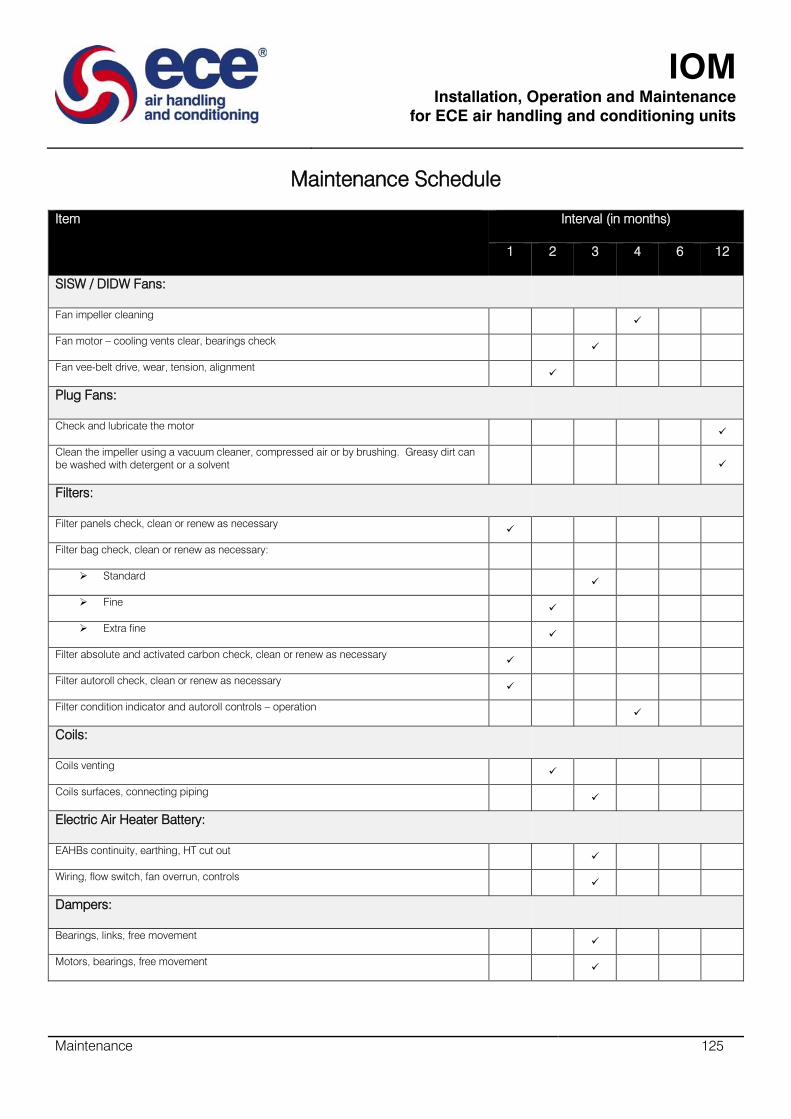
IOM
Installation, Operation and Maintenance
for ECE air handling and conditioning units
Maintenance 125
Maintenance Schedule
Item
Interval (in months)
1
2
3
4
6
12
SISW / DIDW Fans:
Fan impeller cleaning
Fan motor – cooling vents clear, bearings check
Fan vee-belt drive, wear, tension, alignment
Plug Fans:
Check and lubricate the motor
Clean the impeller using a vacuum cleaner, compressed air or by brushing. Greasy dirt can
be washed with detergent or a solvent
Filters:
Filter panels check, clean or renew as necessary
Filter bag check, clean or renew as necessary:
Standard
Fine
Extra fine
Filter absolute and activated carbon check, clean or renew as necessary
Filter autoroll check, clean or renew as necessary
Filter condition indicator and autoroll controls – operation
Coils:
Coils venting
Coils surfaces, connecting piping
Electric Air Heater Battery:
EAHBs continuity, earthing, HT cut out
Wiring, flow switch, fan overrun, controls
Dampers:
Bearings, links, free movement
Motors, bearings, free movement

IOM
Installation, Operation and Maintenance
for ECE air handling and conditioning units
Maintenance 126
Gas Burners:
All points
Humidifiers:
Humidifier cylinder electrodes
Humidifier controls, wiring, piping
General Maintenance:
Metal, paint, sealing strips, sealant, fixings
Insulation, A/Vs, flex, connections, fixings
Wiring, controls, earth continuity
* indicates a one-off activity
This Schedule is not intended to be exclusive, inclusive or mandatory. Different conditions of use may dictate shorter or longer periods and or more
intensive action.

IOM
Installation, Operation and Maintenance
for ECE air handling and conditioning units
Maintenance 127
SISW / DIDW - Fan Bearings
Spider Arm Bearing
Sealed ball races mounted in rubber, pre-greased and self-aligning for service free use under normal duties.
TL3 up to 400 and TL3 450-630
THLZ Duplex – 3 No. spider arm bearings
Units in the ECE range fitted with spider arm bearings

IOM
Installation, Operation and Maintenance
for ECE air handling and conditioning units
Maintenance 128
Plummer Block Bearing
Sealed ball races, mounted in cast iron supports, self-aligning and pre-greased with grease points.
Extended shaft ‘A’ frame
NTH3 T1 and T2 710 – 1000
Units in the ECE range fitted with Pillow Block bearings

IOM
Installation, Operation and Maintenance
for ECE air handling and conditioning units
Maintenance 129
Replacing the filters (for HTM specification units)
All filters are fitted to universal filter frames. The filters are fixed using C70 clips. To replace a filter:
Unclip the fastening pins and pivot them in their base
Once all the clips are loosened the filter will start to come out from the top. Pull the filter out and check neoprene
tape for damage, replacing as required

IOM
Installation, Operation and Maintenance
for ECE air handling and conditioning units
Maintenance 130
Push the new filter into the frame, making sure the pleats are all vertical and the filter seals against the neoprene
tape
Re-fasten the C70 pins

IOM
Installation, Operation and Maintenance
for ECE air handling and conditioning units
Maintenance 131
Motor Bearings
Self-aligning self-oiling and spring loaded ball lubricators, use light machine oil.
Pressure grease fittings and relief plugs, wipe down fitting, remove pressure plug (if fitted) and hardened grease.
Add grease till NEW grease is expelled, run motor for 10 minutes, stop motor, clean and replace plus.
The bearing should be repacked with Shell Alvania 2, BP Energygrease 2 or Esso Beacon 2, leaving room for
expansion (These greases are suitable for temperatures between -30 C and + 110C).
If a rumble, knock or scrape is heard the motor should be replaced or examined and repaired by an electric motor
repair specialist.
NEVER subject the shaft to hard blows, as this may cause damage to the bearings resulting in noisy running and
reduce list.
Motors without Grease Points
Remove belts, run motor and apply the tip of a screwdriver to motor body (not shaft!) and the handle to your ear. A
purring sound should be heard. If a squeaking noise is heard the bearing is dry and should be cleaned and flushed,
out with a mixture of Tuoline and methylated alcohol (or, in an emergency, white spirit, never petroleum or paraffin).
Motor Overheating
Check for overheating, ascertain cause and rectify.
Washable Filters
Wash in mild detergent, rinse and squeeze dry.
Autoroll Filters
Check oil level in gearbox, lightly oil chain drive, lubricate drive motor, oil end of roll indicator arm.
Activated Carbon (Constantly Monitored)
When gas absorption drops below limiting level remove, replace with spare set and sent laden set for reactivation of
discard.
Activated Carbon (disposable non-monitored)
After 1 month usage remove test element or one cell (install new cell) and send for analysis and prediction of remaining
life. Replace filters completely within predicted period.

IOM
Installation, Operation and Maintenance
for ECE air handling and conditioning units
Maintenance 132
Electric Heater Batteries
Particularly check condition of wiring and insulation, plus surrounding paintwork/metalwork for signs of overheating.
Dampers - Motors
Lightly oil damper and motor bearings and link swivels – except nylon bearings.
Coils - General
Check finned surfaces every six months for build-up of dirt or lint. If required wash down with mild detergent solution and
soft brush and blow out any solids between fins with compressed air line. Take care not to disturb the fin surfaces or
probe the coils with metal scraper as damage may cause leaks.
At six monthly intervals ensure that the condensate drain lines are unobstructed and functioning.
DX Cooling Coils
During winter the refrigerant should be pumped over into the liquid receiver and the isolating valve shut. Enough gas
should be left in the system to keep a positive pressure in it. Before restarting, the plant should be checked for refrigerant
leaks.
IOM
Installation, Operation and Maintenance
for ECE air handling and conditioning units
Fault Finding 133
Fault Finding

IOM
Installation, Operation and Maintenance
for ECE air handling and conditioning units
Fault Finding 134
Centrifugal Fans
Fault Check
NO AIR FLOW
Fan motor stationery
No current to motor
Motor connected
Wiring or isolator (on?)
Fuses intact
Wiring to starter (on?)
Starter wired properly
Overloads holding in and correct size
Wiring to time clock at “on phase”
Wiring to panel/mains (on?)
Other control circuits holding fan(s) off (eg. gas fired heater warm
up)
NO AIR FLOW
Fan motor running
Current to motor
Jammed impeller
Seized fan/motor bearings
Drive belts too tight
Motor windings/wiring faulty
Motor wrongly connected
Wrong voltage
NO AIR FLOW
Fan motor running
Fan stationery
Jammed impeller
Drive belts loose or missing
Impeller loose or missing
NO AIR FLOW
Fan running
Louvres blocked
VCD’s closed
Filters blocked
Cooling coil frozen solid
Duct blocked
Fire damper link failed
Grilles closed
LOW AIR FLOW
Check as for no air flow plus:-
Fan rotation incorrect
Filters back to front
Media wrong
Drive belts slack or greasy
Pulley ratios wrong
Duct resistance exceeds design
Duct leaking on pressure side
Access doors off
Duct joint not sealed
HIGH AIR FLOW
Low initial clean filter resistance
Filter missing
Duct incomplete or leaking
Pulley ratios wrong
Backward bladed impeller installed as
forward
System resistance over estimated
MOTOR CURRENT
EXCEEDS NAMEPLATE F.L.C.
Check as for no airflow, low air flow, high air flow

IOM
Installation, Operation and Maintenance
for ECE air handling and conditioning units
Fault Finding 135
Electric Heaters
Fault Check
NO HEAT
All controls, protective devices and interlocks as described in
“Commissioning” section are installed
Thermostat setting too low
Time clock at “on” phase
Filters clean
Airflow adequate
Isolator connected
Mains switch on
Power from mains
All wiring connected
High temperature cut out button in
Continuity across H.T. cut out terminals
Airflow switch making and breaking
Voltage to airflow switch terminals
Contactor coil functioning properly
Fuses not blown
Step controller functioning properly
Fan - EAHB interlock functioning properly
If low airflow refer to “Low Airflow” centrifugal fan section.
If the high temperature cut out has operated
do not run system until reason for “cut out”
has been found.
LOW HEAT
Wrong elements supplied
Element failure (open circuit or down to earth)
Elements disconnected
Elements incorrectly wired
Wrong voltage
Thermostat too low
Step controller sticking/faulty
Wiring fault
Other controller equipment fault
Cooling Coils
Fault Check
NO COOLING
Current to plant
Thermostat setting too high/faulty
Time clock at “on” phase
Motor not connected
Overloads tripped
(continue checks as for airflow in “fans”)
NO COOLING
HP cut out functioning
Correct setting
Faulty condenser
Heat rejection faulty
Fans and pumps stopped
Condenser blocked
LOW OR NO COOLING
LP cut out functioning
Suction pressure/evaporating temperature too low
Coil freezing up
Condenser too large for evaporator
Low air flow
Uneven air flow
Low entering air temperature
Humidistat(s) calling for dehumidification
Low compressor capacity control installed and functioning
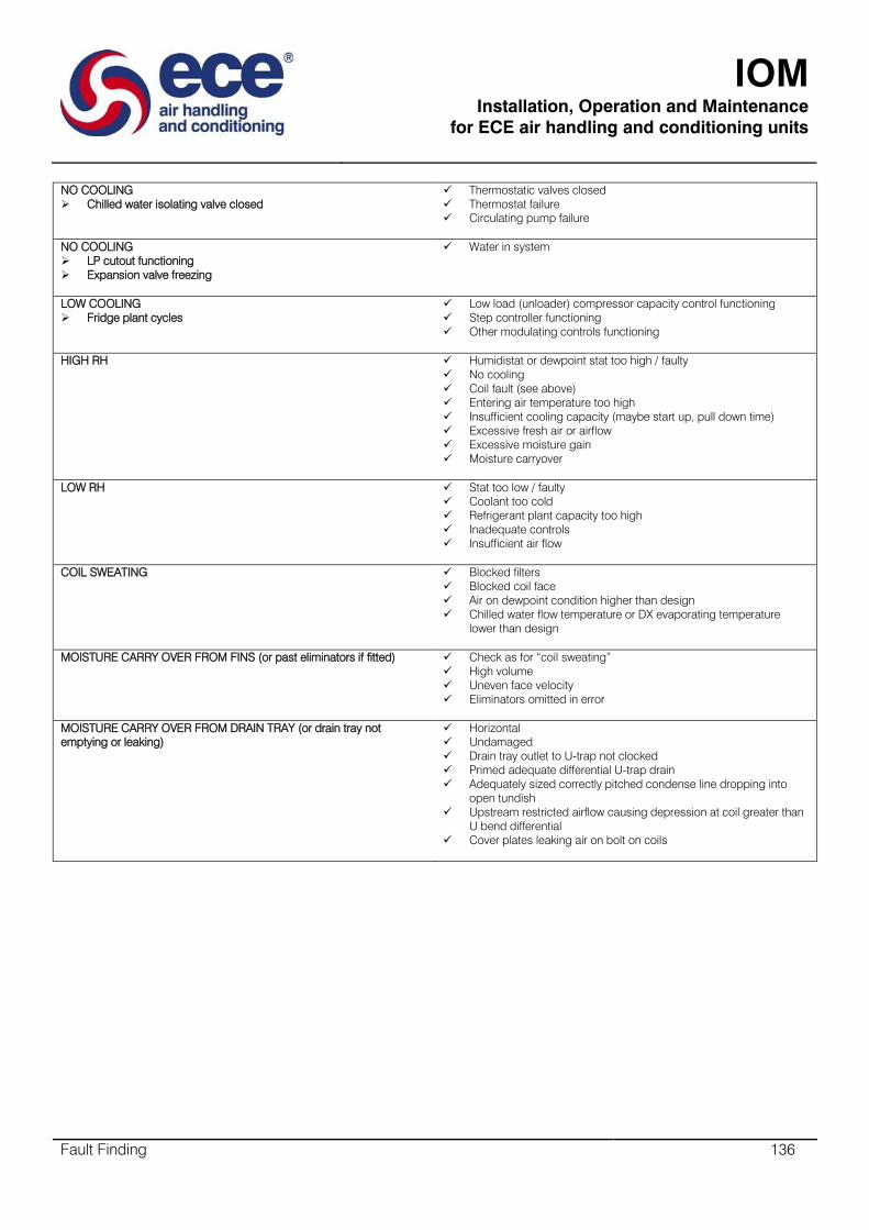
IOM
Installation, Operation and Maintenance
for ECE air handling and conditioning units
Fault Finding 136
NO COOLING
Chilled water isolating valve closed
Thermostatic valves closed
Thermostat failure
Circulating pump failure
NO COOLING
LP cutout functioning
Expansion valve freezing
Water in system
LOW COOLING
Fridge plant cycles
Low load (unloader) compressor capacity control functioning
Step controller functioning
Other modulating controls functioning
HIGH RH
Humidistat or dewpoint stat too high / faulty
No cooling
Coil fault (see above)
Entering air temperature too high
Insufficient cooling capacity (maybe start up, pull down time)
Excessive fresh air or airflow
Excessive moisture gain
Moisture carryover
LOW RH Stat too low / faulty
Coolant too cold
Refrigerant plant capacity too high
Inadequate controls
Insufficient air flow
COIL SWEATING
Blocked filters
Blocked coil face
Air on dewpoint condition higher than design
Chilled water flow temperature or DX evaporating temperature
lower than design
MOISTURE CARRY OVER FROM FINS (or past eliminators if fitted)
Check as for “coil sweating”
High volume
Uneven face velocity
Eliminators omitted in error
MOISTURE CARRY OVER FROM DRAIN TRAY (or drain tray not
emptying or leaking)
Horizontal
Undamaged
Drain tray outlet to U-trap not clocked
Primed adequate differential U-trap drain
Adequately sized correctly pitched condense line dropping into
open tundish
Upstream restricted airflow causing depression at coil greater than
U bend differential
Cover plates leaking air on bolt on coils
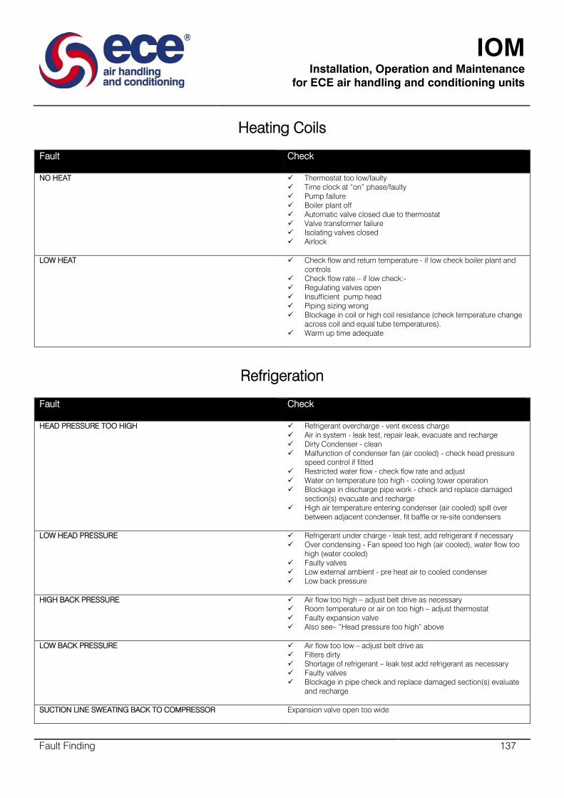
IOM
Installation, Operation and Maintenance
for ECE air handling and conditioning units
Fault Finding 137
Heating Coils
Fault Check
NO HEAT
Thermostat too low/faulty
Time clock at “on” phase/faulty
Pump failure
Boiler plant off
Automatic valve closed due to thermostat
Valve transformer failure
Isolating valves closed
Airlock
LOW HEAT
Check flow and return temperature - if low check boiler plant and
controls
Check flow rate – if low check:-
Regulating valves open
Insufficient pump head
Piping sizing wrong
Blockage in coil or high coil resistance (check temperature change
across coil and equal tube temperatures).
Warm up time adequate
Refrigeration
Fault Check
HEAD PRESSURE TOO HIGH Refrigerant overcharge - vent excess charge
Air in system - leak test, repair leak, evacuate and recharge
Dirty Condenser - clean
Malfunction of condenser fan (air cooled) - check head pressure
speed control if fitted
Restricted water flow - check flow rate and adjust
Water on temperature too high - cooling tower operation
Blockage in discharge pipe work - check and replace damaged
section(s) evacuate and recharge
High air temperature entering condenser (air cooled) spill over
between adjacent condenser, fit baffle or re-site condensers
LOW HEAD PRESSURE
Refrigerant under charge - leak test, add refrigerant if necessary
Over condensing - Fan speed too high (air cooled), water flow too
high (water cooled)
Faulty valves
Low external ambient - pre heat air to cooled condenser
Low back pressure
HIGH BACK PRESSURE
Air flow too high – adjust belt drive as necessary
Room temperature or air on too high – adjust thermostat
Faulty expansion valve
Also see– “Head pressure too high” above
LOW BACK PRESSURE
Air flow too low – adjust belt drive as
Filters dirty
Shortage of refrigerant – leak test add refrigerant as necessary
Faulty valves
Blockage in pipe check and replace damaged section(s) evaluate
and recharge
SUCTION LINE SWEATING BACK TO COMPRESSOR Expansion valve open too wide
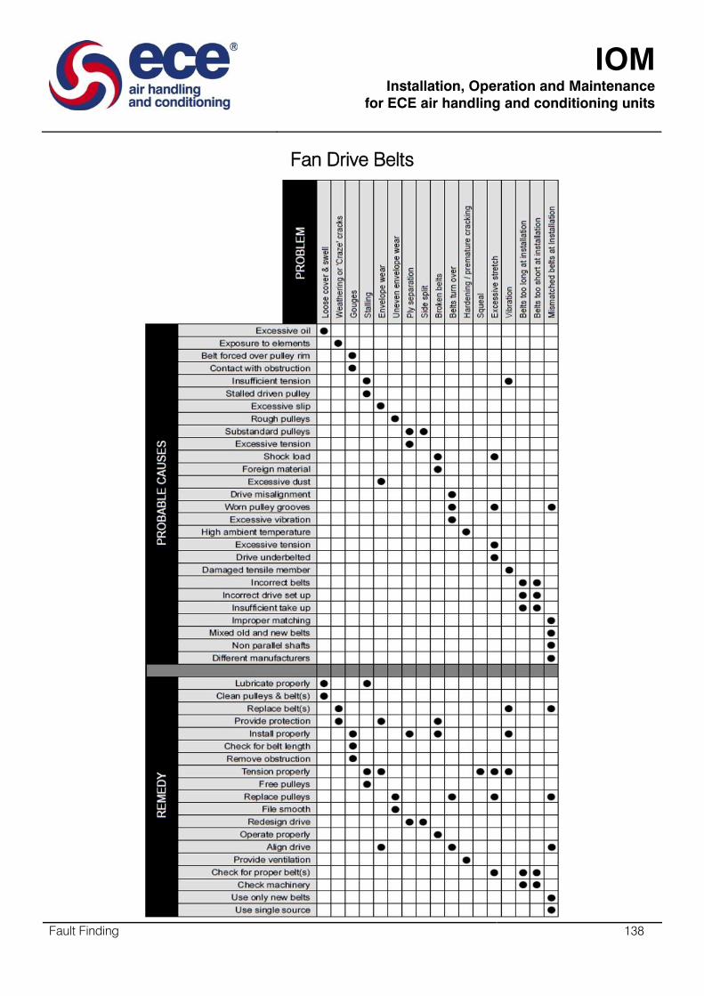
IOM
Installation, Operation and Maintenance
for ECE air handling and conditioning units
Fault Finding 138
Fan Drive Belts