ece 4900 megaphone & filter laboratory: pre-lab instructions · pdf fileece 4900 megaphone...
TRANSCRIPT

336014D012 – Final Report
1
ECE 4900 Megaphone & Filter Laboratory: Pre-Lab Instructions
Introduction
Communication is a fundamental skill that mankind has used over the course of history. Electronic forms of sending messages
have revolutionized the way we go about our everyday lives. It used to take days by postal mail to send information; now it takes
only seconds to relay text, video, pictures, and more. In the upcoming lab, you will see first-hand an example of a simple electronic
communications device: the megaphone. At the most basic level, your megaphone will convert your speech into weak electrical
impulses, which in turn are amplified, fed to a magnetic speaker, and recreated back into audio waves. In the next section, we’ll
explain how this is done with a simple electrical circuit and explain the physical theory behind the phenomena.
Theory: Megaphone Lab
The first key component to our circuit is the microphone, which will convert input audio into an AC signal. The circuit
representation of the microphone is shown in Figure 1.
Figure 1: Microphone Circuit Representation Microphones are active components; they detect audio perturbations and translate them to sinusoidal electrical ripples centered on a
non-zero voltage. To realize a non-zero voltage, we need to bias the device appropriately for it to work. For this lab, we only have to
bias the microphone at Vcc, so we can use a single resistor to limit current and provide a proper voltage to the positive node of the
microphone, shown in Figure 2.

336014D012 – Final Report
2
Figure 2: Properly biased Microphone Audio signals are oscillating waves, where the frequency of the wave determines the pitch of the sound. As such, the speech
information is contained in the AC part of the signal, not the DC. Since we’re only interested in amplifying the audio signal which is
intrinsically AC (audio ranges from around 20 Hz-20 kHz) and not the microphone’s DC bias, we need some way to decouple the AC
part of the transmission from the bias level. For this purpose we use a simple passive component: the capacitor. As you may
remember from your linear circuits or physics coursework, the expression for the impedance of a capacitor in terms of angular
frequency is 𝑍𝑍𝑐𝑐 = 1𝑗𝑗𝑗𝑗𝑗𝑗
, where 𝜔𝜔 = 2𝜋𝜋𝜋𝜋with 𝜋𝜋 as the signal frequency. Direct current signals are 0 in frequency, so taking the limit
of 𝑍𝑍𝑐𝑐 as 𝜋𝜋 goes to 0, we see lim𝑓𝑓→0
𝑍𝑍𝑐𝑐 = ∞, which means a capacitor is a theoretical open to DC components. As for the AC
components they are scaled by 1𝑗𝑗𝑗𝑗
and phase shifted by 90 degrees, but are able to pass through linearly with frequency. For example
say we input 𝐴𝐴𝐴𝐴𝐴𝐴𝐴𝐴(𝜔𝜔𝜔𝜔)to a capacitor; the corresponding output would be 𝐴𝐴𝑗𝑗𝑗𝑗
cos (𝜔𝜔𝜔𝜔 − 90°). For this reason, we will use a capacitor
to perform our DC decoupling as shown in Figure 3.

336014D012 – Final Report
3
Figure 3: Microphone with Decoupling Capacitor Now that we have a small circuit set up translating audio waves into a mostly pure AC signal we can focus on the section of our
circuit that you will be focusing the most on during your lab: the preamplifier (pre-amp) circuit. For the amplifier to properly
function it needs to be fed with the correct voltage ranges. The pre-amp circuit aims to accomplish this goal. The most fundamental
component of our pre-amp topology is the operational amplifier, also known as an op-amp, which you should recognize from
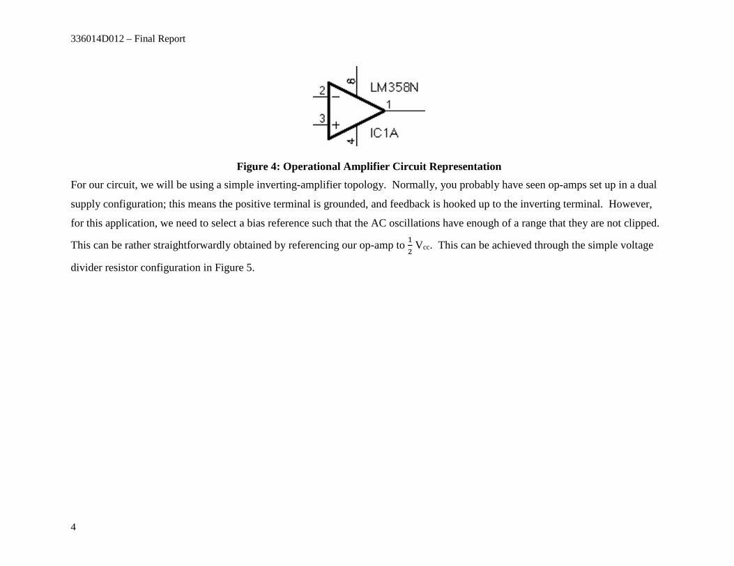
previous coursework. The schematic symbol for our op-amp is shown in Figure 4. Pins 1, 2, 3, 4 and 6 are indicative of the output,
inverting input, non-inverting input, negative supply rail and positive supply rail respectively.
336014D012 – Final Report
4
Figure 4: Operational Amplifier Circuit Representation For our circuit, we will be using a simple inverting-amplifier topology. Normally, you probably have seen op-amps set up in a dual
supply configuration; this means the positive terminal is grounded, and feedback is hooked up to the inverting terminal. However,
for this application, we need to select a bias reference such that the AC oscillations have enough of a range that they are not clipped.
This can be rather straightforwardly obtained by referencing our op-amp to 12 Vcc. This can be achieved through the simple voltage
divider resistor configuration in Figure 5.

336014D012 – Final Report
5
Figure 5: Voltage Divider Connected to the Op-Amp Now that we’ve properly biased the op-amp, we can concern ourselves with using negative feedback to create the appropriate amount
of signal gain.
336014D012 – Final Report
6
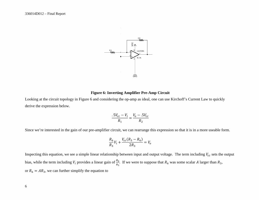
Figure 6: Inverting Amplifier Pre-Amp Circuit Looking at the circuit topology in Figure 6 and considering the op-amp as ideal, one can use Kirchoff’s Current Law to quickly
derive the expression below.
. 5𝑉𝑉𝑐𝑐𝑐𝑐 − 𝑉𝑉𝑖𝑖𝑅𝑅1
=𝑉𝑉𝑜𝑜 − .5𝑉𝑉𝑐𝑐𝑐𝑐
𝑅𝑅2
Since we’re interested in the gain of our pre-amplifier circuit, we can rearrange this expression so that it is in a more useable form.
𝑅𝑅6𝑅𝑅3𝑉𝑉𝑖𝑖 +
𝑉𝑉𝑐𝑐𝑐𝑐(𝑅𝑅3 − 𝑅𝑅6)2𝑅𝑅3
= 𝑉𝑉𝑜𝑜
Inspecting this equation, we see a simple linear relationship between input and output voltage. The term including 𝑉𝑉𝑐𝑐𝑐𝑐 sets the output
bias, while the term including 𝑉𝑉𝑖𝑖 provides a linear gain of 𝑅𝑅6𝑅𝑅3
. If we were to suppose that 𝑅𝑅6 was some scalar 𝐴𝐴 larger than 𝑅𝑅3,
or 𝑅𝑅6 = 𝐴𝐴𝑅𝑅3, we can further simplify the equation to

336014D012 – Final Report
7
𝐴𝐴𝑉𝑉𝑖𝑖 +𝑉𝑉𝑐𝑐𝑐𝑐(1− 𝐴𝐴)
2= 𝑉𝑉𝑜𝑜
Depending on the problem requirements of 𝑉𝑉𝑜𝑜(output to the amplifier) this equation can be used to find an appropriate resistor ratio 𝐴𝐴.
Again, we find that we need to decouple the DC component �𝑉𝑉𝑐𝑐𝑐𝑐(1−𝐴𝐴)2
� from our pre-amp output, so we again affix a capacitor as
shown below; completing our preamp circuit.
Figure 7: Complete Pre-Amplifier Circuit Now that we have a usable pre-amp circuit in Figure 7, we can finally hook up the amplifier portion of this lab by connecting
PRE_OUT to AMP_IN. Since the amplifier circuit is not the focus of this experiment, it is sufficient to this of the amplifier as more
or less a similar circuit to the pre-amp, but with a larger gain. The schematic for the amplifier chip is shown in Figure 8.

336014D012 – Final Report
8
Figure 8: Amplifier Schematic The key part to take away from the amplifier circuit is to recognize that its sole purpose is to provide a high enough voltage to drive
the speaker. The speaker is comprised of an inductor coil with a magnetic housed in the middle. The magnet is connected to a
flexible speaker cone. Changing voltage through the inductive coil changes the paraxial magnetic field running through the center of
the inductor. This changing field causes the magnet and cone to vibrate accordingly; the cone’s vibrations produce sound waves
which we then can hear with our ears. A diagram is shown below (Figure 9) to help illustrate this phenomena. Had we just hooked
up the microphone to the speaker, the voltage would not have been high enough to move the magnet.

336014D012 – Final Report
9
Figure 9: Speaker Diagram
Calculations: Megaphone Lab
For your lab, the microphone must be biased at Vcc, the preamp output must have an A value of 100, Vcc is 9V.
𝑅𝑅1 =____________ (Ohms)
𝑅𝑅2 =____________ (Ohms)
𝑅𝑅3 = ____________ (Ohms)
𝑅𝑅4 =____________ (Ohms)
𝑅𝑅5 =____________ (Ohms)
𝑅𝑅6 = ________________(Ohms)
336014D012 – Final Report
10
Theory: Filter Lab
All analog electronics have some sort of noise associated with them. This can result from electrons being excited randomly
by photons, phonons, among many other sources. Noise, which you will experience in your lab, can often make electrical signals
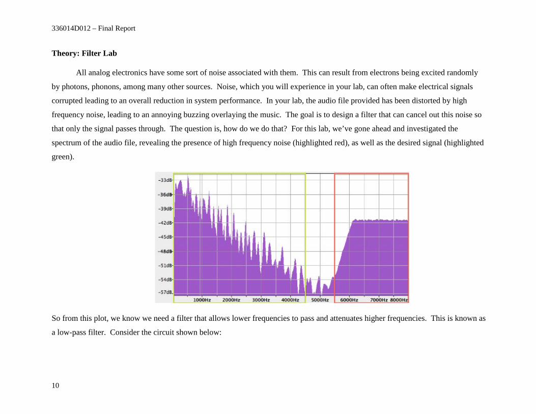
corrupted leading to an overall reduction in system performance. In your lab, the audio file provided has been distorted by high
frequency noise, leading to an annoying buzzing overlaying the music. The goal is to design a filter that can cancel out this noise so
that only the signal passes through. The question is, how do we do that? For this lab, we’ve gone ahead and investigated the
spectrum of the audio file, revealing the presence of high frequency noise (highlighted red), as well as the desired signal (highlighted
green).
So from this plot, we know we need a filter that allows lower frequencies to pass and attenuates higher frequencies. This is known as
a low-pass filter. Consider the circuit shown below:

336014D012 – Final Report
11
Earlier, we talked about how a capacitor acts as an open for low frequency and a short for high frequency. In this circuit topology,
high frequency signals are shorted to ground, while the lower frequencies will be slightly attenuated. A quick nodal analysis shows
that:
1𝑅𝑅9𝑋𝑋(𝑗𝑗𝜔𝜔) = 𝑌𝑌(𝑗𝑗𝜔𝜔) �
1𝑅𝑅9
+ 𝑗𝑗𝜔𝜔𝐶𝐶6�
We can easily derive the transfer function of the circuit as
𝑌𝑌(𝑗𝑗𝜔𝜔)𝑋𝑋(𝑗𝑗𝜔𝜔) = 𝐻𝐻(𝑗𝑗𝜔𝜔) =
1𝑅𝑅9(𝑗𝑗𝜔𝜔𝐶𝐶6) + 1
Taking the magnitude of 𝐻𝐻(𝑗𝑗𝜔𝜔) yields:
|𝐻𝐻(𝑗𝑗𝜔𝜔)| =1
�(𝑅𝑅9𝜔𝜔𝐶𝐶6)2 + 1

336014D012 – Final Report
12
Setting |𝐻𝐻(𝑗𝑗𝜔𝜔)| equal to 12 or -3dB yields a final expression useful for calculating a cutoff frequency:
𝜔𝜔3𝑑𝑑𝑑𝑑𝑐𝑐𝑑𝑑𝑑𝑑𝑜𝑜𝑓𝑓𝑓𝑓 =1
𝑅𝑅9𝐶𝐶6, 𝜋𝜋3𝑑𝑑𝑑𝑑𝑐𝑐𝑑𝑑𝑑𝑑𝑜𝑜𝑓𝑓𝑓𝑓 =
12𝜋𝜋𝑅𝑅9𝐶𝐶6
So, any frequency above 𝜋𝜋3𝑑𝑑𝑑𝑑𝑐𝑐𝑑𝑑𝑑𝑑𝑜𝑜𝑓𝑓𝑓𝑓 will effectively be attenuated to less than half of its amplitude by our circuit. We can now
therefore select a proper resistance and capacitance to suppress the high frequency noise, while letting our lower audio file
frequencies pass through.
Calculations: Filter Lab
𝑅𝑅9 =____________ (Ohms)
𝐶𝐶6 =____________ (Farads)

336014D012 – Final Report
13
Post lab questions:
1) Explain the difference between a low pass filter and a high pass filter. Which frequencies are attenuated by each filter and which frequencies are let through. Give examples of an application for each filter for.
2) Given the following inverted configuration:
http://en.wikipedia.org/wiki/Operational_amplifier_applications
a)If we wanted a voltage gain of -100 and Rin is 125𝛺𝛺 what would Rf need to be?
b) If Rf = 2.5𝑘𝑘𝛺𝛺 and Rin = 120𝛺𝛺 what is the voltage gain?
336014D012 – Final Report
14
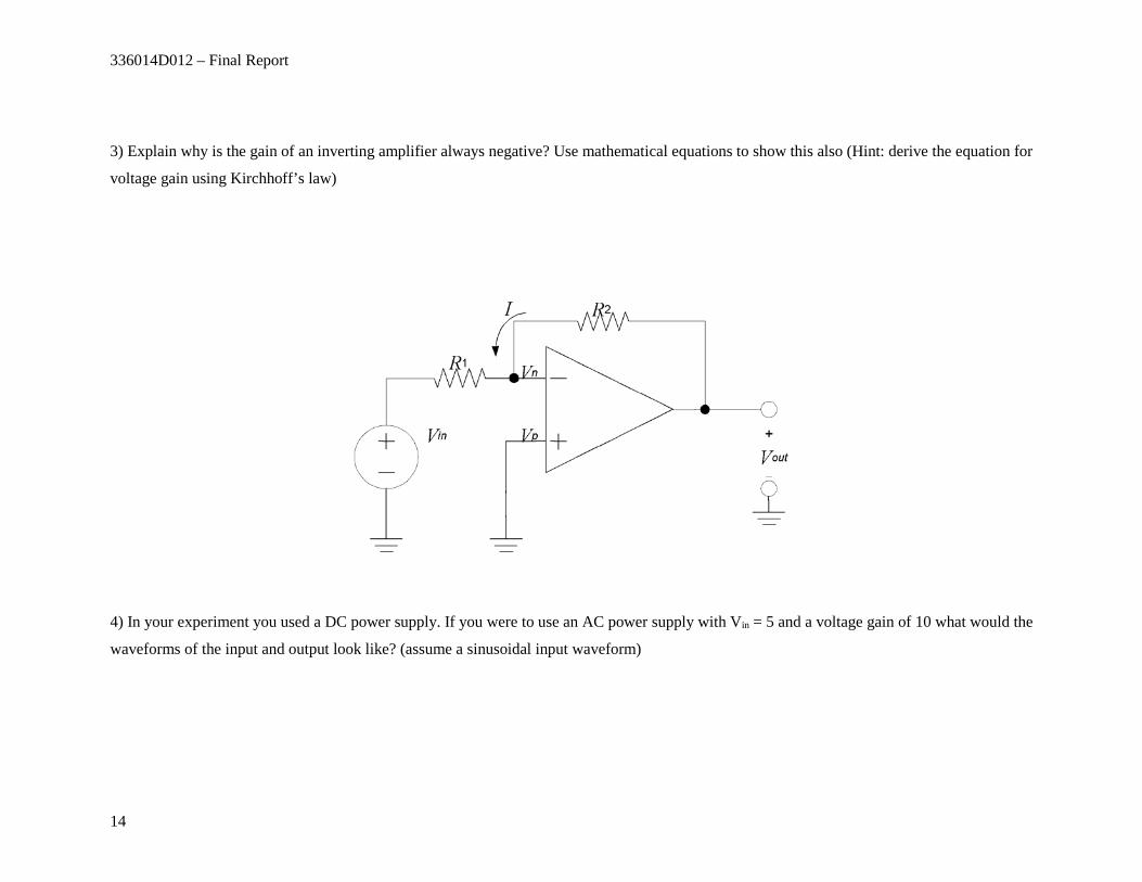
3) Explain why is the gain of an inverting amplifier always negative? Use mathematical equations to show this also (Hint: derive the equation for
voltage gain using Kirchhoff’s law)
4) In your experiment you used a DC power supply. If you were to use an AC power supply with Vin = 5 and a voltage gain of 10 what would the
waveforms of the input and output look like? (assume a sinusoidal input waveform)

336014D012 – Final Report
15
Solutions:
1) Low pass filters attenuate high frequencies and let low frequencies pass through. High pass filters attenuate low frequencies and let high
frequencies pass through.
Students may put anything that makes sense for the application of the filter. It is up to the professor whether it is acceptable or not. Examples:
Low pass filters are used in music recordings to take out background noise clearing up the recording. High pass filters are used in cable boxes to
block low frequency DCs signals and only let in radio frequency signals.
2) a) Av = − 𝑅𝑅𝑓𝑓𝑅𝑅𝑖𝑖𝑖𝑖
→ 𝑅𝑅𝑓𝑓 = −𝐴𝐴𝑣𝑣𝑅𝑅𝑖𝑖𝑖𝑖 → Rf = -100 * 125 𝛺𝛺 → Rin = 12.5 k 𝛺𝛺
b) Av = − 𝑅𝑅𝑓𝑓𝑅𝑅𝑖𝑖𝑖𝑖
→ Av = -2500/120 = -20.833
336014D012 – Final Report
16
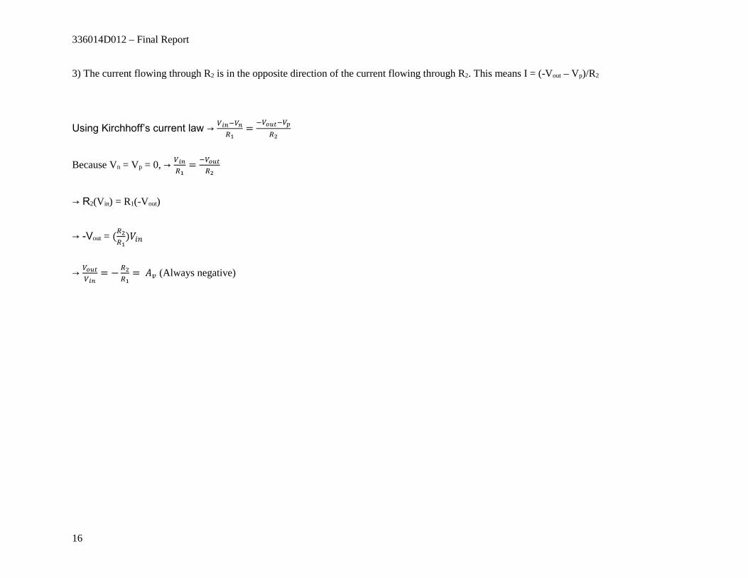
3) The current flowing through R2 is in the opposite direction of the current flowing through R2. This means I = (-Vout – Vp)/R2
Using Kirchhoff’s current law → 𝑉𝑉𝑖𝑖𝑖𝑖−𝑉𝑉𝑖𝑖𝑅𝑅1
= −𝑉𝑉𝑜𝑜𝑜𝑜𝑜𝑜−𝑉𝑉𝑝𝑝𝑅𝑅2
Because Vn = Vp = 0, → 𝑉𝑉𝑖𝑖𝑖𝑖𝑅𝑅1
= −𝑉𝑉𝑜𝑜𝑜𝑜𝑜𝑜𝑅𝑅2
→ R2(Vin) = R1(-Vout)
→ -Vout = (𝑅𝑅2𝑅𝑅1
)𝑉𝑉𝑖𝑖𝑖𝑖
→ 𝑉𝑉𝑜𝑜𝑜𝑜𝑜𝑜𝑉𝑉𝑖𝑖𝑖𝑖
= −𝑅𝑅2𝑅𝑅1
= 𝐴𝐴𝑣𝑣 (Always negative)

336014D012 – Final Report
17
4) Input signal waveform:

336014D012 – Final Report
18
Output signal waveform: