ece 477 digital systems senior design project module 11 ... · clicker quiz. 1. a soldering iron...
TRANSCRIPT

ECE 477 Digital SystemsSenior Design Project
© 2011 by D. G. Meyer© 2011 by D. G. Meyer
Module 11Board Assembly and Soldering Techniques

Outline
� “I’ve got my board, now what?”
� “Which end of this thing gets hot?”
“Flux is your friend.”� “Flux is your friend.”
� “Static is your enemy.”
� “Do unto your iron, as you would have it do unto you.”

“I’ve got my board, now what?” - 1� Visually inspect board against printout of
top/bottom copper� Confirm footprint and drill size of all parts
� Minimum trace: 0.0049”
� Minimum space: 0.0045”
Minimum finished hole size: 0.010”� Minimum finished hole size: 0.010”
� If necessary, use drill press in lab to drill out any holes that need to be enlarged (e.g., headers)
� Problem: your vias will already be plated!
� Look for shorted traces and traces that got etched away (will be limited need to do this)
� Using a sharp hobby knife, carefully scrape away copper that did not get etched between traces
� “Fly wire” any traces that got etched away
� If “major” problems – contact fab house for replacement
“I’ve got my board, now what?” - 2
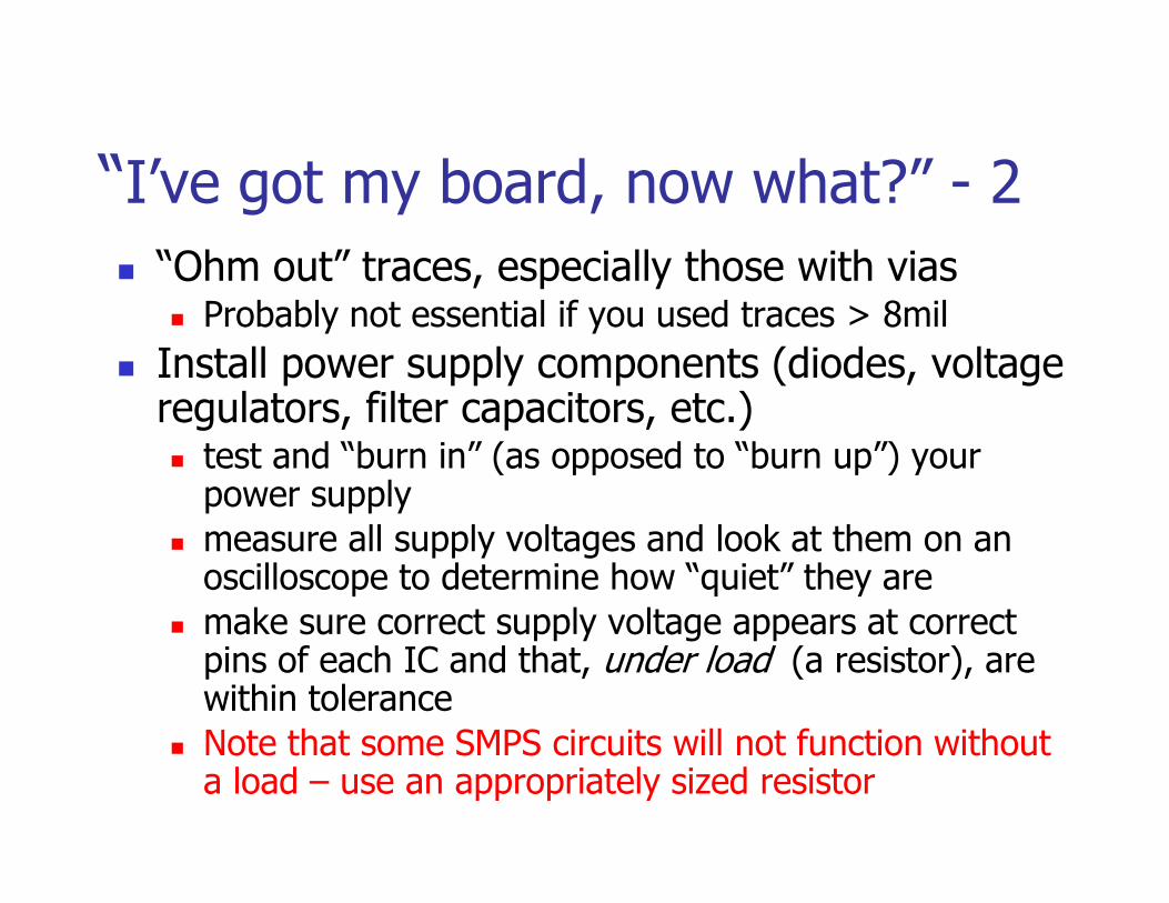
� “Ohm out” traces, especially those with vias� Probably not essential if you used traces > 8mil
� Install power supply components (diodes, voltage regulators, filter capacitors, etc.)� test and “burn in” (as opposed to “burn up”) your � test and “burn in” (as opposed to “burn up”) your
power supply
� measure all supply voltages and look at them on an oscilloscope to determine how “quiet” they are
� make sure correct supply voltage appears at correct pins of each IC and that, under load (a resistor), are within tolerance
� Note that some SMPS circuits will not function without a load – use an appropriately sized resistor

“I’ve got my board, now what?” - 3
� Install all bulk and bypass capacitors and test all supply rails again to make sure nothing got “shorted” in the process
� Install microcontroller, reset circuit, crystal (or oscillator) circuit, flash programming (or oscillator) circuit, flash programming header, and any other test points/headers� power up the board and “smoke test”
(hint: if the microcontroller starts to get warm real fast, something is wrong!)
� load a simple “heartbeat” program that toggles a port pin – verify basic functionality

“I’ve got my board, now what?” - 4
� Install RS232 level translator chip (where applicable) and associated components (9-pin D connector, capacitors, etc.)
� power up and “smoke test”
� load a simple program that “echoes” data � load a simple program that “echoes” data to/from a virtual terminal – verify basic functionality “HELLO WORLD”
� Add each interface circuit to your board block-by-block and “smoke test” each one as well as test/verify functionality
“I’ve got my board, now what?” - 5
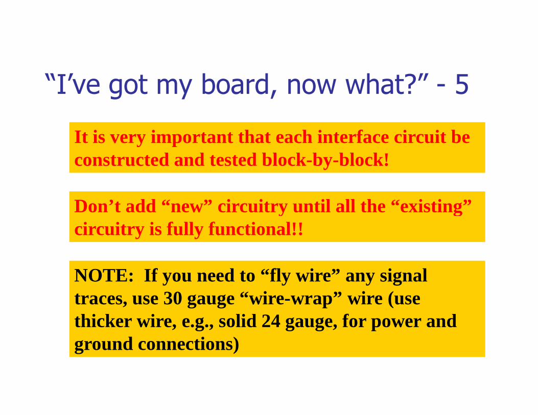
It is very important that each interface circuit be constructed and tested block-by-block!
Don’t add “new” circuitry until all the “existing” Don’t add “new” circuitry until all the “existing” circuitry is fully functional!!
NOTE: If you need to “fly wire” any signal traces, use 30 gauge “wire-wrap” wire (use thicker wire, e.g., solid 24 gauge, for power and ground connections)
“Which end of this thing gets hot?” - 1
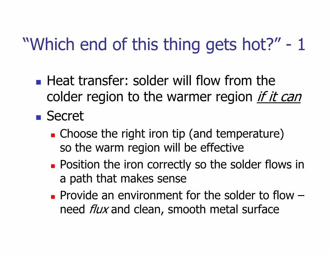
� Heat transfer: solder will flow from the colder region to the warmer region if it can
� Secret
Choose the right iron tip (and temperature) � Choose the right iron tip (and temperature) so the warm region will be effective
� Position the iron correctly so the solder flows in a path that makes sense
� Provide an environment for the solder to flow –need flux and clean, smooth metal surface
“Which end of this thing gets hot?” - 2
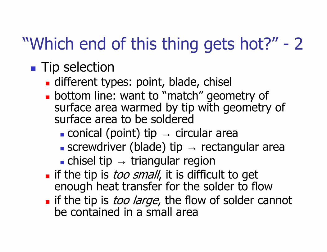
� Tip selection� different types: point, blade, chisel� bottom line: want to “match” geometry of
surface area warmed by tip with geometry of surface area to be soldered
conical (point) tip → circular area� conical (point) tip → circular area� screwdriver (blade) tip → rectangular area� chisel tip → triangular region
� if the tip is too small, it is difficult to get enough heat transfer for the solder to flow
� if the tip is too large, the flow of solder cannot be contained in a small area
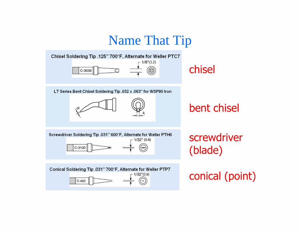
Name That Tip
chisel
bent chisel
screwdriver (blade)
conical (point)
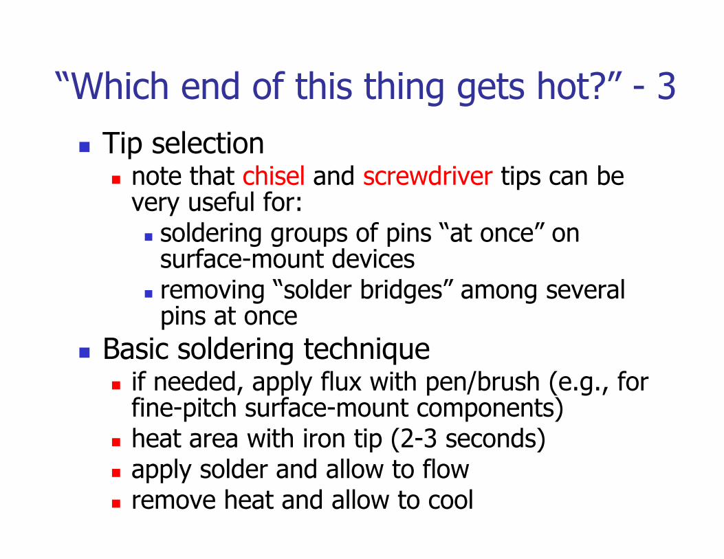
“Which end of this thing gets hot?” - 3
� Tip selection� note that chisel and screwdriver tips can be
very useful for:� soldering groups of pins “at once” on
surface-mount devicesremoving “solder bridges” among several � removing “solder bridges” among several pins at once
� Basic soldering technique� if needed, apply flux with pen/brush (e.g., for
fine-pitch surface-mount components)� heat area with iron tip (2-3 seconds)� apply solder and allow to flow� remove heat and allow to cool

Using the Right Amount of Solder
a) Minimal b) Optimal c) Excessive
see http://www.elexp.com/t_solder.htm

What’s Wrong With These Pictures?
see http://www.elexp.com/t_solder.htm
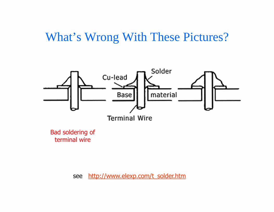
What’s Wrong With These Pictures?
see http://www.elexp.com/t_solder.htm
Bad soldering of terminal wire
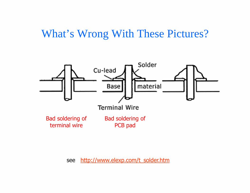
What’s Wrong With These Pictures?
see http://www.elexp.com/t_solder.htm
Bad soldering of terminal wire
Bad soldering of PCB pad

What’s Wrong With These Pictures?
see http://www.elexp.com/t_solder.htm
Bad soldering of terminal wire
Bad soldering of PCB pad
Bad soldering of both (solder did
not flow properly)

“Which end of this thing gets hot?” - 4
� Solder removal (de-soldering)� apply flux (if necessary)� heat area to be de-soldered (surface-mount
parts require a special heat gun to do this)� use solder wick (copper braid) or “solder
sucker” to remove solder� use solder wick (copper braid) or “solder
sucker” to remove solder
� Cautions� “cold” solder joints (solder did not flow)� too much heat (components will be damaged
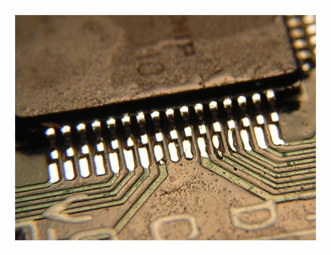
and/or traces will peel off board)� access (be careful about assembly order!)� examine solder joints of surface mount
components using microscope
“Flux is your friend.”
� Flux is a liquid in which solder can flow
� Most “electronic” solder contains some flux
� Without flux, solder will be pasty and sticky (refuse to flow)
� The secret to soldering is using flux to make solder flow, and then controlling the heat so it flows under control
“Static is your enemy.”
� Many of the parts you will be using are static sensitive (can be damaged by ESD)
� To avoid damaging your components, do To avoid damaging your components, do all of your board construction on the anti-static (blue/gray) mats in lab
� When soldering, use an anti-static wrist band and make sure it is connected to ground

“Do unto your iron, as you would have it do unto you.”
� Wet the sponge with distilled water before
you begin
� Choose the iron with the appropriate tip for the job and set the temperature accordinglythe job and set the temperature accordingly
� Tin and clean the tip before starting
� Clean the tip frequently during use
� Tin the tip when you are finished and TURN OFF the iron
� Use soldering irons only for soldering!


ECE 477 – Module 11Clicker QuizClicker Quiz

1. A soldering iron tip that can effectively be used to solder QFP surface mount packages is a: QFP surface mount packages is a:
A. small screwdriver tipB. conical tipC. large chisel tip D. all of the aboveE. none of the above
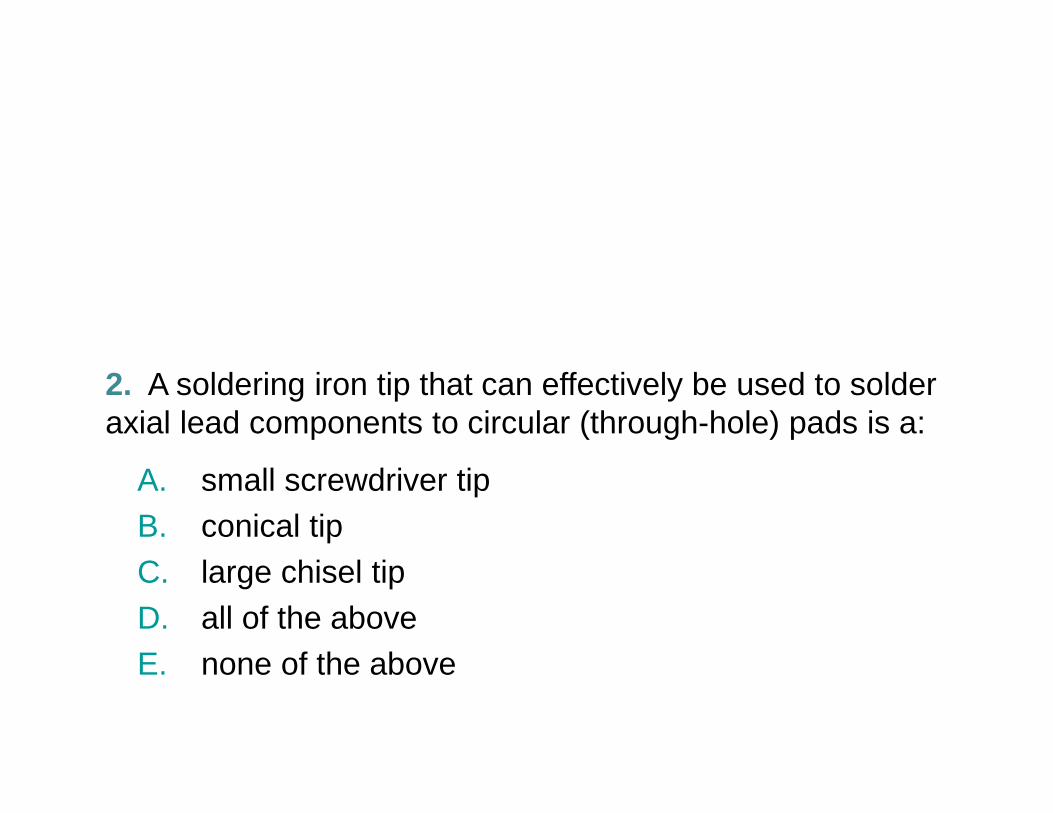
2. A soldering iron tip that can effectively be used to solder axial lead components to circular (through-hole) pads is a: axial lead components to circular (through-hole) pads is a:
A. small screwdriver tipB. conical tipC. large chisel tip D. all of the aboveE. none of the above
3. A soldering iron tip that can effectively be used to solder surface mount resistors or capacitors is a: surface mount resistors or capacitors is a:
A. small screwdriver tipB. conical tipC. large chisel tip D. all of the aboveE. none of the above
4. Proper care of a soldering iron tip includes: 4. Proper care of a soldering iron tip includes:
A. removing oxidation with sandpaper or a fileB. spraying the soldering tip with waterC. constantly tinning the tip when the iron is on D. cleaning the tip in a solution of HKN coffeeE. none of the above

5. Other potential uses for the soldering irons in lab include: 5. Other potential uses for the soldering irons in lab include:
A. warming HKN coffeeB. boring holes in plasticC. engraving wooden plaques D. waking up sleeping teammatesE. none of the above