eccentric plug control valve - mbee.ae · for several industrial process control. the exl––®...
TRANSCRIPT
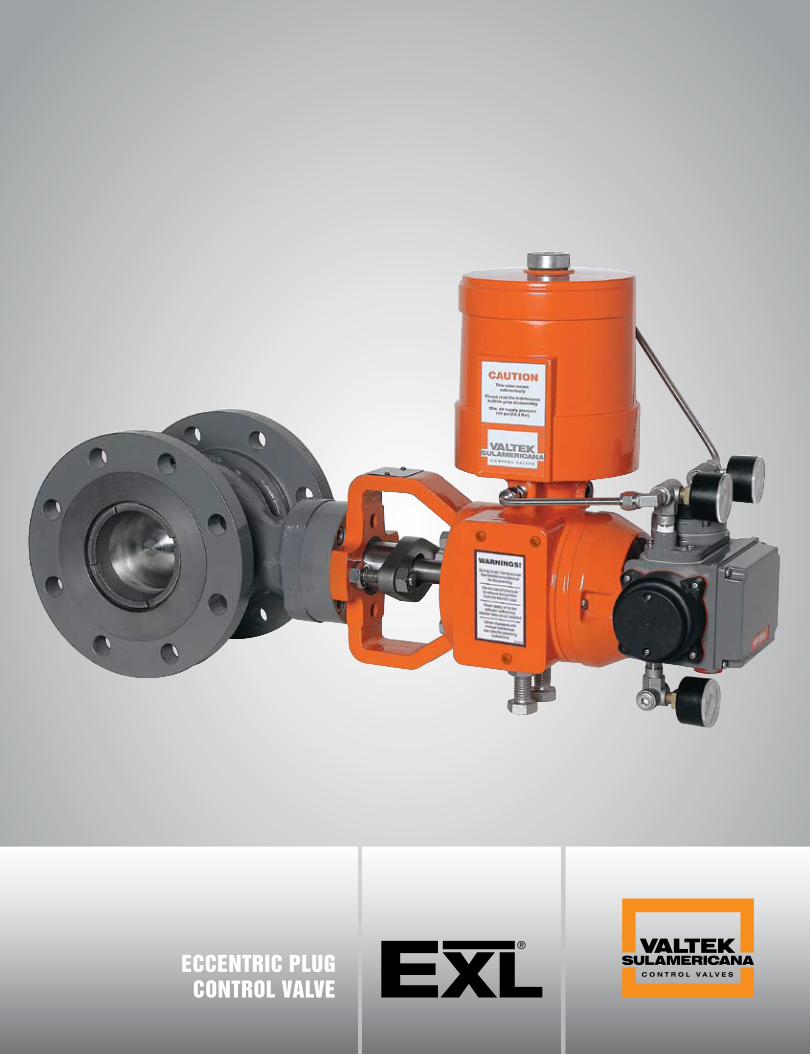
eccentric plugcontrol valve

2 EXL__
ECCENTRIC PLUG CONTROL VALVE VALTEK SULAMERICANA
Rotary control valves are being
used more and more due to their
large flow capacity, high rangea-
bility, compact sizes, superior shaft
sealing capacity and a broad range
of applications meaning the solution
for several industrial process control.
The EXL––® eccentric plug control
valve was developed as a simple, light-
weight and more economical alterna-
tive to the renowned and advanced
design of Valtek Sulamericana eccen-
tric plug control valve model EP.
The EXL––® control valve was desig-
ned to handle differential pressures
up to 725 psi (50 Bar), temperature
range from –150 to 752ºF (-100 to
400ºC) and is available in sizes from
1 to 8 inches with ANSI classes 150 –
300 or DIN PN 16 – 40.
Its eccentric plug provides range-
ability over 160:1, considered excel-
lent when compared to the 30:1
rangeability of globe valves and 20:1
of the majority of butterfly valves.
For each valve size, several re-
duced trim are also available. Thanks
to these trim options, it is possible
to obtain a broad range of nomi-
nal Cv´s, allowing on several appli-
cations, an accurate and refined con-
trol of the fluid through the valve.
BODY SUB-ASSEMBLY (FIGURE 1)
Rangeability higher than 160:1
ANSI Class IV Shutoff — Metal Seat ANSI Class VI Shutoff — Soft Seat
Non-crossover shaft withanti-blowout system pro-
vides a higher Cv
Eccentric rotary plug whichpulls out immediately fromseat ring, reducing trim wear
Stationary post
I N T R O D U C T I O N

EXL__
ECCENTRIC PLUG CONTROL VALVE 3VALTEK SULAMERICANA
C O N S T R U C T I O N / S E A T I N G
VALVE OPEN (FIGURE 2) STATIONARY POST (FIGURE 3)
ReabilityEquipped with a rugged and non-crossover shaft, which
does not restrict the fluid flow, the EXL–– ® valve provides high-
er capacity for each nominal size. Its advanced constructioneliminates damages caused by corrosive/abrasive process fluids.
In most traditional rotary valves, the shaft usually passesthrough the valve body causing significant reduction of flowcapacity and increasing shaft wear. The EXL
–– ® valve config-uration ensures a high flow capacity. While in the open po-sition, the streamlined flow passageway suffers no interfe-rence, since the plug is totally retracted into the body core.
When the plug moves to the closed position, its doubleeccentricity feature makes it turn into the seat at a tiltingangle that eliminates metal-to-metal sliding contact (fig. 2).It also eliminates the wear that would require frequentmaintenance, consequently reducing operating costs.
As the valve opens and the plug slides smoothly offthe seat, the occurrence chances of water hammer effectare drastically reduced. Due to its “zero breakout tor-que” feature, the EXL
–– ® allows the use of smaller actu-
ators, significantly reducing maintenance time and costs.Since the shaft-plug does not cause flow restriction,
the EXL–– ® provides higher flow coefficient (Cv) than any
other rotary plug control valve existing in the market.The combination of a large and rugged stationary
post (Fig. 3) with the oversized plug and shaft made fromhardened 17-4PH as standard material provide excellentshutoff features and increase trim lifetime.
These characteristics combined with the use of: spring-cylinder actuators with proven lifetime longer than a mil-lion of cycles; HPP1500 Analog or HPP3000 and HPP3500Digital Positioners, which provide and accurate and refinedprocess control; Packing boxes with large depth that meetthe EPA* requirements; Shaft with anti-blowout system thatcomplies with ANSI B16.34; Trim with full area or reducedto 70% or 40% of area able to control a wide range of flow ra-tes, make the EXL
–– one of the most modern, advanced andaccurate eccentric rotary plug valve in the world market.*EPA = U. S. Environmental Protection Agency

4 EXL__
ECCENTRIC PLUG CONTROL VALVE
A C T U A T O R S / S P E C I F I C A T I O N S
VALTEK SULAMERICANA
Actuators The RA-XL spring-cylinder rotary actuator com-
bines high torque and pneumatic stiffness with anexcellent controllability. These characteristics areintegrated into a single, rugged, lightweight andcompact assembly, which makes it the ideal choicefor rotary valves driving.
The RA-XL double acting spring-cylinder actu-ator is designed to operate with air supply pressuresup to 150 psi (10.3 Bar), reaching high operatingtorques. The actuator Series RA-XL has a provenlifetime longer than a million of cycles, whichmakes it the most reliable actuator in the market.The double acting positioner feeds both cylinderchambers simultaneously, ensuring an exceptionalstiffness. This pneumatic stiffness makes the actu-ator Series RA-XL insuperable when an accuratecontrol of the valve positioning is required, evenwhen the valve is operating at small openings.
These features enable a much better perfor-mance of the actuator Series RA-XL when com-pared with the spring-diaphragm actuators.
High parts interchangeability – Reduces the need for spare parts
Lightweight and compact design –Helps handling and needs limited space
Rockingpistondirectlyconnectedto theshaft
Sliding collar
assemblyfor reliable
and long lifeoperation
Splined shaft thateliminates
motion losses
Adjustable stroke stops prevent excessive rotation and reduce excessive torque on shaft
Actuator spring forfailsafe action
Type Double acting cylinderwith positive spring for failsafe actionField reversible
Sizes 25, 50, 100, 200
Action Air-to-OpenAir-to-CloseFail-in-place
Air Supply Up to 150 psi maximum Pressure 10.3 Bar maximum
Stroking Speed Aprox. 1 inch/sec.*
Operating -40 to 350˚FTemperature (-40 to 175˚C)
Auxiliary handwheel Declutchable SideAssembly Manual, gear operatedLever
Positioners HPP1500 AnalogHPP3000 DigitalHPP3500 Digital
ROTARY ACTUATOR SERIES RA-XL (FIGURE 4)
ACTUATOR SPECIFICATIONS (TABLE I)
* Sizes 25 and 50 with 60 psig air supply.

EXL__
ECCENTRIC PLUG CONTROL VALVE 5VALTEK SULAMERICANA
PositionersFOR THROTTLING APPLICATIONS, THE RO-TARY ACTUATORS SERIES RA-XL ALLOW THEUSE OF SEVERAL POSITIONER OPTIONS.
Yoke Ductile Iron
Transfer Case Anodized Aluminum
Splined Lever Arm Nickel Plated Ductile Iron
Actuator Stem UNS S 41600 Stainless Steel
BearingsTeflon reinforced with fiberglass filaments
Sliding Collar DelrinoR, Aluminum
CylinderRetaining Ring
Zinc Plated steel
Piston Anodized Aluminum
Cylinder Anodized Aluminum
O-rings* Buna N (Standard)
Actuator Spring Steel (corrosion proof)
Spring Button Carbon Steel
* Room temperature higher than 180°F (82°C) require Viton o-rings.Temperatures lower than -40°F (-40°C) require Fluorsilicone o-rings.
DIGITAL HPP3500 SERIES (FIGURE 5)
DIGITAL HPP3000 SERIES (FIGURE 6)
ANALOG HPP1500 SERIES (FIGURE 7)
This positioner has the same characteristics ofHPP3000, 4-20 mAcc input signal and HART®
protocol. This project was developed to make eas-ier the positioner installation on rotary actuatorswith NAMUR interface. Intrinsically safe, thispositioner is provided with NEMA 4X and IECIP66 enclosure and can handle air supply pressu-res from 20 to 100 psig (1.4 to 6.9 Bar ) at opera-ting temperatures from – 40 to 176˚F (-40 - 80˚C).
This is a high performance microprocessed positioner, compatible withHART®, DE and Fieldbus communication protocols or 4-20 mAcc analog sig-nal, also programmable for several split range configuration. This positionerSeries incorporates totally programmable functions such as: auto-tunning,manual and automatic modes, multiple communication protocols and dia-gnostic information, which contribute to increase productivity and efficien-cy of industrial plant operations and to lower maintenance. The digital posi-tioner Series HPP3000 can handle air supply pressures from 20 to 100 psig(1.4 to 6.9 Bar) at operating temperatures from – 40 to 176˚F (-40 to 80˚C).
This is a single or double acting high performance positioner. It allowsthe use of a pneumatic module for pneumatic input signals or an analogelectro-pneumatic module for control signals in milliamps. Highly resis-tant and using the state-of-the-art technology, it works with air supply pres-sures up to 150 psig (10.3 Bar) without requiring air pressure regulatorsand withstands ambient temperatures from –40 to 176˚F (-40 to80˚C). The positioner Series HPP1500 allows two or three split-rangeconfigurations with the use of a specific cam.
MATERIALS OF CONSTRUCTION (TABLE II)

6 EXL__
ECCENTRIC PLUG CONTROL VALVE
C O N S T R U C T I O N / M A T E R I A L S
VALTEK SULAMERICANA
High performanceEquipped with rugged and oversized shaft and sta-
tionary post, positioned by bearings with a broad supportsurfaces, the design of EXL
–– ® shaft/bearing system pro-vides remarkable wear reduction and considerablyextends the valve lifetime.
The standard material for the valve plug is the stainlesssteel 17-4PH hardened by heat treatment. However, thetrim (plug and seat) can be made also from Alloy #6, provi-ding excellent shutoff features and extending the valve useto a wide range of applications such as, flashing process li-quids, erosive services, mild cavitations and steam service.
The EXL–– ® non-crossover shaft design prevents obstruc-
tions in the line, assuring a full flow passageway. When thevalve is open, the fluid is not deviated towards the seat orthe seat retainer, allowing great reliability even after manyyears in service.
The plug and driving shaft assembly is done by meansof a precise splined connection, which eliminates the useof keys and pins that may be destroyed and lost due tocorrosion or vibration effects. The sturdiness of the rigidand extra-strong seat makes the valve performance excel-lent for applications with high pressure drops. The typi-cal maintenance cycle for the EXL
–– ® exceeds a 5-year peri-od and its lifetime expectation exceeds a 20-years period.
Additional AdvantagesAfter evaluating the EXL
–– ® from the reliability point ofview, other considerations shall be taken into accountregarding its performance such as: Flow capacity up to70% larger when compared to eccentric rotary plug valvesfrom other manufacturers; Can be used on pulp andpaper processes with consistency up to 3% due to itsdesign with a non-crossover shaft; In closed position, itsdesign allow pressure drops up to 725 psi (50 Bar); thevalve can be mounted either with shaft upstream or down-stream; Reduced trim with 70 or 40% of area; ShutoffANSI class IV with metal seats or class VI with soft seats;Shaft with anti-blowout system which eliminates the riskof personnel injuries, fire and process shutdown; Fixedstationary post, which is not damaged by process fluid; 90˚plug rotation allowed by using high performance doubleacting actuator with spring return for failsafe position.
* The body rating and packing temperature vs. pressure limits shall not be exceeded.
MATERIALTEMPERATURE*
˚F ˚C
PTFE “V” Rings -150 to 450 -100 to 232
Braided PTFE -150 to 500 -100 to 260
Graphite -20 to 752 -28 to 400
PT -20 to 450 -28 to 232
PTG -20 to 450 -28 to 232
PTG XT -20 to 550 -28 to 288
ASSEMBLY FLOW DIRECTION APPLICATION
Standard –right side
Shaft downstreamFluid towards the plug convex face
Clean FluidsFluids with nocavitation and nor flashing
Standard –left side
Shaft upstreamFluid towards the plug back face
Fluids with solidparticles, abrasive,flashing or cavitating fluids.
Sizes (inches) 1; 1.5; 2; 3; 4; 6; 8
EndConnections
RF FlangesFlangeless
Face Finish 125-250 Ra Standard
RatingsANSI Class 150-300DIN PIN 16 – 40
Face-to-FaceDimension ANSI/ISA-75.08.02
Trim Area 100% Full Area70% Reduced Area40% Reduced Area (1 to 6 in.)
Shutoff ANSI Class IV with metal seatANSI Class VI with soft seat
OperatingTemperature -150 to 752ºF (-100 to 400ºC)
FLOW DIRECTION (TABLE IV)
TEMPERATURE LIMITS FOR PACKINGS (TABLE V)
BODY SPECIFICATIONS (TABLE III)

ITEMMATERIAL
CLASSIFICATION
SPECIFICATION
ASTM CODE (AMS No.) UNS Code HARDNESS RC
Body 316 (Casting) A 351 Gr CF8M J 92900
Plug 17-4 PH (Casting) A 747 Gr CB7-Cu-1 J 92180 35-38
316L // Alloy #6 (1) A 351 CF3M // AMS 5387 J 92800 // R 30006 40-42
Shaft 17-4 PH (Bar) A 564 Gr 630 S 17400 35
Post 17-4 PH (Casting) A 747 Gr CB7-Cu-1 J 92180 35-38
Bearings (Plug and Shaft) Ultimet B 818 R 31233 30
Seat Retainer 316 (Casting) A 351 Gr CF8M J 92900
Metal Seat 316 (Bar) A 479 Gr 316 S 31600
316L // Alloy #6 (1) A 351 CF3M // AMS 5387 J 92800 // R 30006 40-42
Soft Seat 316 (Bar) // PTFE A 479 Gr 316 S 31600
Shaft Retainer 316 (Bar) // Ultimet A 479 Gr 316 // B 818 S 31600 // R 31233 8 // 30
Gland Flange 316 (Casting) A 351 Gr CF8M J 92900
Packing Follower 316 (Bar) A 479 Gr 316 S 31600
Packing Spacers 316 (Bar) A 479 Gr 316 S 31600
EXL__
ECCENTRIC PLUG CONTROL VALVE 7
ITEMMATERIAL
CLASSIFICATIONSPECIFICATION
ASTM CODE (AMS No.) UNS Code HARDNESS RC
Body Carbon Steel (Casting) A 216 WCB J 03002
Plug 17-4 PH (Casting) A 747 Gr CB7-Cu-1 J 92180 35-38
316L // Alloy #6 (1) A 351 CF3M // AMS 5387 J 92800 // R 30006 40-42
Shaft 17-4 PH (Bar) A 564 Gr 630 S 17400 35
Post 17-4 PH (Casting) A 747 Gr CB7-Cu-1 J 92180 35-38
Bearings (Plug and Shaft) 440C (Bar) A 276 S 44004 55-60
Seat Retainer 316 (Casting) A 351 Gr CF8M J 92900
Metal Seat 316 (Bar) A 479 Gr 316 S 31600
420 (Casting) A 743 Gr CA40 J 91153 38-45
316L // Alloy #6 (1) A 351 CF3M // AMS 5387 J 92800 // R 30006 40-42
Soft Seat 316 (Bar) // PTFE A 479 Gr 316 S 31600
Shaft Retainer 316 (Bar) // 440 (Bar) A 479 Gr 316 // A 276 S 31600 // S 44004 8 // 55-60
Gland Flange 316 (Casting) A 351 Gr CF8M J 92900
Packing Follower 316 (Bar) A 479 Gr 316 S 31600
Packing Spacers 316 (Bar) A 479 Gr 316 S 31600
STANDARD MATERIALS OF CONSTRUCTION STAINLESS STEEL SUB-ASSEMBLY (TABLE VII)
STANDARD MATERIALS OF CONSTRUCTION CARBON STEEL SUB-ASSEMBLY (TABLE VI)
(1) Solid Alloy #6 for valves with sizes up to 4 inches.
(1) Solid Alloy #6 for valves with sizes up to 4 inches.
VALTEK SULAMERICANA

8 EXL__
ECCENTRIC PLUG CONTROL VALVE
MATERIAL CLASSPRESSURE TEMPERATURE
PSI BAR ˚F ˚C
Carbon SteelASTM A 216 Gr. WCB
ANSI 150
285 19.7 -20 to 100 -29 to 38
260 17.9 200 93
230 15.9 300 149
200 13.8 400 204
170 11.7 500 260
140 9.7 600 316
125 8.6 650 343
110 7.6 700 371
95 6.6 750 399
ANSI 300
740 51.0 -20 to 100 -29 to 38
675 46.5 200 93
655 45.2 300 149
635 43.8 400 204
600 41.4 500 260
550 37.9 600 316
535 36.9 650 343
535 36.9 700 371
505 34.8 750 399
Stainless SteelASTM A 351 Gr. CF8M
ANSI 150
275 19.0 -20 to 100 -29 to 38
235 16.2 200 93
215 14.8 300 149
195 13.4 400 204
170 11.7 500 260
140 9.7 600 316
125 8.6 650 343
110 7.6 700 371
95 6.6 750 399
ANSI 300
720 49.7 -20 to 100 -29 to 38
620 42.8 200 93
560 39.4 300 149
515 35.5 400 204
480 33.1 500 260
450 31.0 600 316
445 30.7 650 343
430 29.7 700 371
425 29.3 750 399
VALTEK SULAMERICANA
M A T E R I A L S
* Maximum allowable pressure drop based on shaft resistance with full area seat. Body rating shall not be exceeded.
VALVE SIZE SHAFT DIAMETER SEAT DIAMETER(FULL AREA)
MAX. ALLOWABLE PRESSURE DROP* (90º ROT.)
SHAFT UPSTREAM SHAFT DOWNSTREAM
Inches DN Inches mm Inches mm PSI BAR PSI BAR1 25 0.44 10.8 .71 18.0 725 50 725 50
1.5 40 0.62 15.9 1.10 28.0 725 50 725 50
2 50 0.62 15.9 1.46 37.0 725 50 725 50
3 80 0.88 22.3 2.36 60.0 725 50 725 50
4 100 0.88 22.3 3.03 77.0 725 50 725 50
6 150 1.04 26.5 4.51 114.5 725 50 706 48.7
8 200 1.04 26.5 5.90 149.7 523 36.1 408 28.1
PRESSURE AND TEMPERATURE LIMITS FOR VALVE BODIES – ANSI B 16.34 (TABLE VIII)
MAXIMUM ALLOWABLE PRESSURE DROP* (TABLE IX)

EXL__
ECCENTRIC PLUG CONTROL VALVE 9
P A C K I N G S
VALTEK SULAMERICANA
THE EXL–– ® PACKING BOX HAS A LARGE DEPTH AND AN EXCELLENT FINISH OF INTERNAL SURFACES, WHICH PROVI-
DES A LONGER OPERATING LIFE FOR THE WHOLE PACKING SET. DUE TO ITS DESIGN CHARACTERISTICS, THE EXL–– ®
PACKING BOX ALLOWS THE USE OF A LARGE VARIETY OF PACKING SYSTEMS FOR A BETTER COMPLIANCE WITH THE
MOST STRINGENT STANDARDS CONCERNING FUGITIVE EMISSION CONTROL IN MODERN INDUSTRIAL PROCESSES.
The standard packing of EXL–– ® valves is comprised by
PTFE “V” Rings. The PTFE “V” Rings have been the mostlargely used packing material for many years, with excellenttightness results. Its low friction characteristics, good me-chanical strength and excellent corrosion resistance makeit the most commonly used material for stem and shaft sea-ling. The PTFE “V” rings are used in the EXL
–– ® valve withoperating temperatures from -150 to 450˚F (-100 to 232˚C).
Virgin PTFE
Graphite or braided PTFE
The EXL–– ® packing with molded rings is an option
when the operating temperature exceeds the limits ofPTFE “V” rings. The materials used for EXL
–– ® moldedpackings are braided PTFE for operating temperaturesup to 500˚F (260˚C) and graphite for operating tempera-tures up to 752˚F (400˚C). The graphite molded rings pa-cking is an excellent solution for high temperature appli-cations. However, the high force required for its sealingcauses a considerably friction increase in the valve rotation.
The PT packing type is comprised by a “V” rings set,uniformly and constantly compressed by a mechanicaldevice which includes pairs of belleville washers that acts assprings and provides a “live load” effect. This system reach-es a tightness level below 500 ppm. The PT packing typecombines the superior quality of virgin PTFE rings with car-bon filled PTFE rings. The PTG packing type is comprisedby an advanced set of rings able to maintain levels of emis-sion much lower than 500 ppm (usually 10 ppm). ThePTG packing combines carbon filled PTFE “V” rings withKalrez “V” rings, an advanced material which provides asuperior packing performance. The PTG XT packing typeis used for higher temperatures, up to 550˚F (288˚C). It usesZymax “V” rings replacing the carbon filled PTFE rings.
STANDARD PACKING (FIGURE 8)
HIGH TEMPERATURE PACKING (FIGURE 9)
SPECIAL PACKINGS (FIGURE 10)
Standard Packing:“V” Rings
Double Packing: “V” Rings
Packing: Molded Rings
Double Packing: Molded Rings
PT Packing
PTG Packing
PTFE/Carbon Virgin PTFE
PTFE/Carbon or Zymax® Kalrez®

10 EXL__
ECCENTRIC PLUG CONTROL VALVE
S P E C I F I C A T I O N S / S E L E C T I O N
VALTEK SULAMERICANA
ValveSize
(Inches)
TrimArea
FailurePosition
Actuator Size25 50
Air Supply PressurePSI Bar PSI Bar PSI Bar PSI Bar PSI Bar PSI Bar PSI Bar PSI Bar60 4.1 80 5.5 100 6.9 150 10.3 60 4.1 80 5.5 100 6.9 150 10.3
1
100%OPEN 725 50.0 725 50.0 725 50.0 725 50.0
CLOSED 725 50.0 725 50.0 725 50.0 725 50.0
70%OPEN 725 50.0 725 50.0 725 50.0 725 50.0
CLOSED 725 50.0 725 50.0 725 50.0 725 50.0
40%OPEN 725 50.0 725 50.0 725 50.0 725 50.0
CLOSED 725 50.0 725 50.0 725 50.0 725 50.0
1.5
100%OPEN 725 50.0 725 50.0 725 50.0 725 50.0
CLOSED 725 50.0 725 50.0 725 50.0 725 50.0
70%OPEN 725 50.0 725 50.0 725 50.0 725 50.0
CLOSED 725 50.0 725 50.0 725 50.0 725 50.0
40%OPEN 725 50.0 725 50.0 725 50.0 725 50.0
CLOSED 725 50.0 725 50.0 725 50.0 725 50.0
2
100%OPEN 725 50.0 725 50.0 725 50.0 725 50.0
CLOSED 540 37.2 540 37.2 540 37.2 540 37.2
70%OPEN 725 50.0 725 50.0 725 50.0 725 50.0
CLOSED 725 50.0 725 50.0 725 50.0 725 50.0
40%OPEN 725 50.0 725 50.0 725 50.0 725 50.0
CLOSED 725 50.0 725 50.0 725 50.0 725 50.0
3
100%OPEN 356 24.6 548 37.8 725 50.0 725 50.0 725 50.0 725 50.0 725 50.0 725 50.0
CLOSED 112 7.7 112 7.7 112 7.7 112 7.7 369 25.4 369 25.4 369 25.4 369 25.4
70%OPEN 481 33.2 725 50.0 725 50.0 725 50.0 725 50.0 725 50.0 725 50.0 725 50.0
CLOSED 159 11.0 159 11.0 159 11.0 159 11.0 499 34.4 499 34.4 499 34.4 499 34.4
40%OPEN 725 50.0 725 50.0 725 50.0 725 50.0 725 50.0 725 50.0 725 50.0 725 50.0
CLOSED 256 17.7 256 17.7 256 17.7 256 17.7 725 50.0 725 50.0 725 50.0 725 50.0
4
100%OPEN 206 14.2 322 22.2 439 30.3 725 50.0 725 50.0 725 50.0 725 50.0 725 50.0
CLOSED 58 4.0 58 4.0 58 4.0 58 4.0 214 14.8 214 14.8 214 14.8 214 14.8
70%OPEN 298 20.6 461 31.8 624 43.0 725 50.0 725 50.0 725 50.0 725 50.0 725 50.0
CLOSED 91 6.3 91 6.3 91 6.3 91 6.3 309 21.3 309 21.3 309 21.3 309 21.3
40%OPEN 427 29.4 655 45.2 725 50.0 725 50.0 725 50.0 725 50.0 725 50.0 725 50.0
CLOSED 139 9.6 139 9.6 139 9.6 139 9.6 443 30.6 443 30.6 443 30.6 443 30.6
(1) With downstream shaft and PTFE standard packings (2) Body rating shall not be exceeded.
ValveSize
(Inches)
TrimArea
FailurePosition
Actuator Size50 100
Air Supply Pressure
PSI Bar PSI Bar PSI Bar PSI Bar PSI Bar PSI Bar PSI Bar PSI Bar
60 4.1 80 5.5 100 6.9 150 10.3 60 4.1 80 5.5 100 6.9 150 10.3
6
100%OPEN 298 20.6 445 30.7 592 40.8 706 48.7 706 48.7 706 48.7 706 48.7 706 48.7
CLOSED 65 4.5 65 4.5 65 4.5 65 4.5 403 27.8 403 27.8 403 27.8 403 27.8
70%OPEN 396 27.3 588 40.6 725 50.0 725 50.0 725 50.0 725 50.0 725 50.0 725 50.0
CLOSED 90 6.2 90 6.2 90 6.2 90 6.2 533 36.8 533 36.8 533 36.8 533 36.8
40%OPEN 613 42.3 725 50.0 725 50.0 725 50.0 725 50.0 725 50.0 725 50.0 725 50.0
CLOSED 147 10.1 147 10.1 147 10.1 147 10.1 725 50.0 725 50.0 725 50.0 725 50.0
8100%
OPEN 169 11.7 255 17.6 341 23.5 408 28.1 408 28.1 408 28.1 408 28.1 408 28.1
CLOSED 32 2.2 32 2.2 32 2.2 32 2.2 230 15.9 230 15.9 230 15.9 230 15.9
75%OPEN 228 15.7 342 23.6 456 31.4 544 37.5 544 37.5 544 37.5 544 37.5 544 37.5
CLOSED 47 3.2 47 3.2 47 3.2 47 3.2 309 21.3 309 21.3 309 21.3 309 21.3
MAXIMUM ALLOWABLE PRESSURE DROP(1)(2)
ACTUATOR VERSUS SUPPLY PRESSURE – BAR/PSI (TABLE X)

Plug Seat Bearings Shaft Post
17-4 PH17-4 PH316L/Alloy #6 (1)
316 SS/PTFE 316 stainless steel 316L stainless steel/Alloy #6 (1)
Ultimet Ultimet Ultimet
17-4 PH17-4 PH17-4 PH
17-4 PH17-4 PH17-4 PH
Plug Seat Bearings Shaft Post
316L/Alloy #6 (1)
316L/Alloy #6 (1)
316L/Alloy #6 (1)
316 SS/PTFE 316 stainless steel 316L stainless steel/Alloy #6 (1)
Ultimet Ultimet Ultimet
A 453 Gr 660A 453 Gr 660A 453 Gr 660
A 453 Gr 660A 453 Gr 660A 453 Gr 660
Plug Seat Bearings Shaft Post
316L/Alloy #6 (1)
316L/Alloy #6 (1)
316L/Alloy #6 (1)
316 SS/PTFE 316 stainless steel 316L stainless steel/Alloy #6 (1)
Ultimet Ultimet Ultimet
A 453 Gr 660A 453 Gr 660A 453 Gr 660
A 453 Gr 660A 453 Gr 660A 453 Gr 660
Plug Seat Bearings Shaft Post
17-4 PH17-4 PH17-4 PH316L /Alloy #6 (1)
316 SS/PTFE316 stainless steel420 stainless steel316L stainless steel/Alloy #6 (1)
440C stainless steel440C stainless steel440C stainless steel440C stainless steel
17-4 PH17-4 PH17-4 PH 17-4 PH
17-4 PH17-4 PH17-4 PH 17-4 PH
GASKETS – PRESSURE AND TEMPERATURES LIMITS
(TABLE XII)
EXL__
ECCENTRIC PLUG CONTROL VALVE 11VALTEK SULAMERICANA
CARBON STEEL
CARBON STEEL - NACE
STAINLESS STEEL
STAINLESS STEEL - NACE
BODY SUB-ASSEMBLY – TRIM MATERIALS(TABLE XIII)
Seat Type Process FluidOpen Position Closed Position
Psi Bar Psi Bar
Metal Seat Liquids, Vapors 363 25 725 50,0
Metal Seat Gases 725 50 725 50,0
Soft Seat Liquids, Vapors 145 10 725 50,0
Soft Seat Gases 290 20 725 50,0
Gasket Material
Pressure Temperature
Psi Bar ˚F ˚C
PTFE 725 50 350 176
316 SS/Grafoil 725 50 752 400
(1) Solid Alloy #6 for valves with sizes up to 4 inches.
Body rating shall not be exceeded.
MAXIMUM ALLOWABLE PRESSURE DROPACROSS THE SEAT (TABLE XI)

12 EXL__
ECCENTRIC PLUG CONTROL VALVE
S P E C I F I C A T I O N S / S E L E C T I O N
VALTEK SULAMERICANA
TRIM AREA%
FCT CORRECTION FACTOR = d/D*
0.4 0.5 0.6 0.7 0.8 0.9 1
100 0.91 0.94 0.97 0.99 1
70 0.93 0.94 0.96 0.97 0.98 0.99 1
40 0.98 0.98 0.99 0.99 0.99 0.99 1
CV CORRECTION FACTOR (TABLE XV)
PRESSURE RECOVERY FACTOR, FL (FIGURE 11)
FLUID PLUG SEAT BEARINGS FLOW DIRECTION
Air and Clean Gases* 17-4 PH AISI 316 440C; Ultimet Shaft Upstream
Liquid and Gaseous Hydrocarbons 17-4 PHAlloy #6
AISI 316Alloy #6
440C; Ultimet440C; Ultimet
Shaft DownstreamShaft Downstream
Industrial Liquids 17-4 PH AISI 316 440C; Ultimet Shaft Downstream
Clean Liquids with Cavitation or Flashing17-4 PHAlloy #6
AISI 420Alloy #6
440C; Ultimet440C; Ultimet
Shaft UpstreamShaft Upstream
Non-clean, Muddy or Abrasive LiquidsNon-clean Liquids with Cavitation or Flashing
Alloy #6Alloy #6
Alloy #6Alloy #6
440C; Ultimet440C; Ultimet
Shaft UpstreamShaft Upstream
Non-corrosive Chemical Products 17-4 PH AISI 316 440C Shaft Downstream
Corrosive Chemical Products 17-4 PHAlloy #6
AISI 316Alloy #6
Ultimet Ultimet
Shaft DownstreamShaft Downstream
Water Steam - 150 psi 17-4 PH AISI 420 440C Shaft Downstream
Water Steam - 300 psi Alloy #6 Alloy #6 440C Shaft Downstream
* Except O2
Inf luence of pipe size in f low coef f icient
The nominal Cv values shown inTables XVI and XVII are for assemblieswhere the valve, upstream and down-stream piping have the same size. Whenthe valve is concentrically installed inpiping larger than the valve size, the Cvis affected and must be multiplied bythe “FCT” factor according to table XV.
FL0.90
0.85
0.80
0.75
0.7010 20 30 40 50 60 70 80 90 ROTATION ANGLE (DEGREES)
SHAFT DOWNSTREAM
SHAFT UPSTREAM
d = valve nominal size. D = larger piping size, upstream and downstream
APPLICATION GUIDELINE (TABLE XIV)

FLOW COEFFICIENTS (Cv) - SHAFT UPSTREAM (TABLE XVII)
EXL__
ECCENTRIC PLUG CONTROL VALVE 13
F L O W C O E F F I C I E N T S
VALTEK SULAMERICANA
FLOW – SHAFT DOWNSTREAMSHAFT UPSTREAM – FLOW
Valve Size
(Inches)
TrimArea(%)
OPENING ANGLE (DEGREES)
90 80 70 60 50 40 30 20 10METAL SOFT METAL SOFT METAL SOFT METAL SOFT METAL SOFT METAL SOFT METAL SOFT METAL SOFT METAL SOFT
1100 18 10.3 17 10.1 16 9.3 14 8.2 11.7 6.8 9.1 5.2 6.6 3.8 4.1 2.3 1.8 1.0
70 13 7.1 12 6.9 11 6.4 9.6 5.7 7.9 4.7 6.1 3.6 4.5 2.6 2.7 1.6 1.2 0.7
40 7.1 6.0 7.0 5.9 6.5 5.4 5.7 4.8 4.7 4.0 3.7 3.1 2.7 2.2 1.6 1.4 0.7 0.6
1.5100 46 39 45 38 42 35 37 31 31 26 24 20 17 14.5 10.5 8.8 4.5 3.8
70 33 33 32 32 30 30 26 27 22 22 17 17 12.2 12.3 7.3 7.4 3.2 3.2
40 19 19 18 19 17 17 15 15 12.4 12.6 9.5 9.7 7.0 7.1 4.2 4.3 1.8 1.9
2100 80 71 78 69 72 64 64 57 52 47 40 36 30 26 18 16 7.7 6.9
70 51 51 50 50 46 46 41 41 34 34 26 26 19 19 11.4 11.5 4.9 4.9
40 32 32 31 31 29 29 25 26 21 21 16 16 11.8 11.9 7.2 7.2 3.1 3.1
3100 240 240 234 234 218 218 192 192 160 160 122 122 89 89 54 54 23 23
70 178 178 174 174 161 161 143 143 118 118 91 91 66 66 40 40 17 17
40 103 103 101 101 94 94 82 82 68 68 52 52 38 38 23 23 9.9 9.9
4100 404 404 395 395 366 366 323 323 269 269 205 205 150 150 91 91 39 39
70 266 266 260 260 241 241 213 213 177 177 135 135 99 99 60 60 26 26
40 169 169 165 165 153 153 135 135 112 112 86 86 63 63 38 38 16 16
6100 950 950 928 928 861 861 760 760 631 631 483 483 353 353 214 214 92 92
70 665 665 648 648 602 602 531 531 441 441 337 337 247 247 149 149 64 64
40 380 380 371 371 344 344 304 304 252 252 193 193 142 142 85 85 37 37
8 100 1697 1697 1658 1658 1538 1538 1358 1358 1128 1128 863 863 631 631 370 370 164 164
75 1274 1274 1245 1245 1155 1155 1019 1019 847 847 648 648 474 474 287 287 123 123
Valve Size
(Inches)
TrimArea(%)
OPENING ANGLE (DEGREES)
90 80 70 60 50 40 30 20 10METAL SOFT METAL SOFT METAL SOFT METAL SOFT METAL SOFT METAL SOFT METAL SOFT METAL SOFT METAL SOFT
1100 20 12.0 20 11.9 18 11.0 16 9.7 13.4 8.1 10.2 6.2 7.4 4.6 4.5 2.8 2.0 1.2
70 15 8.3 14.3 8.1 13.3 7.5 11.8 6.6 9.8 5.5 7.5 4.3 5.5 3.1 3.4 1.9 1.4 0.8
40 8.4 6.0 8.2 5.9 7.6 5.5 6.7 4.8 5.6 4.0 4.3 3.1 3.1 2.2 1.9 1.4 0.8 0.6
1.5100 47 39 46 38 42 35 38 31 31 26 24 20 17 14.5 10.6 8.8 4.5 3.8
70 34 34 33 33 31 31 27 28 22 23 17 17 12.6 12.7 7.6 7.7 3.3 3.3
40 19 19 18 18 17 17 15 15 12.6 12.6 9.6 9.6 7.0 7.0 4.3 4.3 1.9 1.9
2100 78 70 76 68 71 64 62 56 52 47 40 36 29 26 18 16 7.5 6.8
70 43 43 42 42 39 39 34 34 28 29 22 22 16 16 9.6 9.7 4.1 4.2
40 24 24 24 23 22 22 19 19 16 16 12.3 12.2 9.0 8.9 5.4 5.4 2.3 2.3
3100 213 213 208 208 193 193 171 171 142 142 108 108 79 79 48 48 20 20
70 166 166 162 162 150 150 132 132 110 110 84 84 62 62 37 37 16 16
40 94 94 92 92 86 86 75 75 63 63 48 48 35 35 21 21 9.2 9.2
4100 308 308 301 301 279 279 246 246 205 205 157 157 114 114 69 69 30 30
70 220 220 215 215 200 200 176 176 146 146 112 112 82 82 50 50 21 21
40 148 148 145 145 134 134 119 119 99 99 75 75 55 55 33 33 14.3 14.3
6100 735 735 718 718 666 666 588 588 488 488 374 374 273 273 165 165 71 71
70 564 564 551 551 511 511 451 451 375 375 287 287 210 210 127 127 54 54
40 326 326 318 318 296 296 261 261 217 217 166 166 121 121 73 73 31 31
8 100 1127 1127 1101 1101 1022 1022 902 902 749 749 573 573 419 419 253 253 109 109
75 850 850 831 831 771 771 680 680 565 565 432 432 316 316 192 192 82 82
FLOW COEFFICIENTS (Cv) - SHAFT DOWNSTREAM (TABLE XVI)

14 EXL__
ECCENTRIC PLUG CONTROL VALVE
D I M E N S I O N S – V A L V E W I T H A C T U A T O R A N D H P P 1 5 0 0 P O S I T I O N E R
VALTEK SULAMERICANA
Valve Size
(Inches)
ANSIclass
ActuatorSize
A B E* F G K** L
Inches mm Inches mm Inches mm Inches mm Inches mm Inches mm Inches mm
1 150-300 25 4.0 102 2.7 69 6.0 152 13.2 335 4.6 116 8.9 227 10.6 268
1.5 150-300 25 4.5 114 2.8 71 6.0 152 13.2 335 4.6 116 8.9 227 11.6 294
2 150-300 25 4.9 124 2.9 74 6.0 152 13.2 335 4.6 116 8.9 227 11.7 296
3150-300 25 6.5 165 4.0 102 6.0 152 13.2 335 4.6 116 8.9 227 13.8 350
150-300 50 6.5 165 4.0 102 8.0 203 18.3 465 5.6 144 9.8 250 13.8 350
4150-300 25 7.6 194 4.2 107 6.0 152 13.2 335 4.6 116 8.9 227 14.0 355
150-300 50 7.6 194 4.2 107 8.0 203 18.3 465 5.6 144 9.8 250 14.0 355
6150-300 50 9.0 229 6.7 171 8.0 203 18.3 465 5.6 144 9.8 250 17.9 455
150-300 100 9.0 229 6.7 171 11.0 279 22.6 575 7.0 179 10.9 276 17.9 455
8150-300 50 9.6 243 7.4 189 8.0 203 18.3 465 5.6 144 9.8 250 18.3 465
150-300 100 9.6 243 7.4 189 11.0 279 22.6 575 7.0 179 10.9 276 18.3 465
DIMENSIONS (TABLE XVIII)
*Clearance required for actuator disassembly. **For HPP1500 pneumatic positioner deduct 2.40 inches (61 mm) from dimension “K”.
“A” = FACE-TO-FACE DIMENSION

EXL__
ECCENTRIC PLUG CONTROL VALVE 15
D I M E N S I O N S – V A L V E W I T H A C T U A T O R A N D H P P 3 5 0 0 P O S I T I O N E R
VALTEK SULAMERICANA
Valve Size
(Inches)
ANSIclass
ActuatorSize
A B E* F G K L
Inches mm Inches mm Inches mm Inches mm Inches mm Inches mm Inches mm
1 150-300 25 4.0 102 2.7 69 6.0 152 13.2 335 4.6 116 7.8 197 10.6 268
1.5 150-300 25 4.5 114 2.8 71 6.0 152 13.2 335 4.6 116 7.8 197 11.6 294
2 150-300 25 4.9 124 2.9 74 6.0 152 13.2 335 4.6 116 7.8 197 11.7 296
3150-300 25 6.5 165 4.0 102 6.0 152 13.2 335 4.6 116 7.8 197 13.8 350
150-300 50 6.5 165 4.0 102 8.0 203 18.3 465 5.6 144 7.8 197 13.8 350
4150-300 25 7.6 194 4.2 107 6.0 152 13.2 335 4.6 116 7.8 197 14.0 355
150-300 50 7.6 194 4.2 107 8.0 203 18.3 465 5.6 144 7.8 197 14.0 355
6150-300 50 9.0 229 6.7 171 8.0 203 18.3 465 5.6 144 7.8 197 17.9 455
150-300 100 9.0 229 6.7 171 11.0 279 22.6 575 7.0 179 7.8 197 17.9 455
8150-300 50 9.6 243 7.4 189 8.0 203 18.3 465 5.6 144 7.8 197 18.3 465
150-300 100 9.6 243 7.4 189 11.0 279 22.6 575 7.0 179 7.8 197 18.3 465
DIMENSIONS (TABLE XIX)
*Clearance required for actuator disassembly.
“A” = FACE-TO-FACE DIMENSION

16 EXL__
ECCENTRIC PLUG CONTROL VALVE
A C T U A T O R – M O U T I N G O R I E N T A T I O N S
VALTEK SULAMERICANA
AIR-TO-CLOSE: FAIL-OPEN AIR-TO-OPEN: FAIL-CLOSE
MOUNTING C MOUNTING D
STANDARD LEFT HAND MOUNTING – SHAFT UPSTREAM
Teflon, Kalrez, Zymax and Delrin are registered trademarks of E.I.DuPont Company. Ultimet is a trademark of Haynes, Int. HARTis a registered trademark of HART Communication Foundation.
AIR-TO-CLOSE: FAIL-OPEN AIR-TO-OPEN: FAIL-CLOSE
www.valteksulamericana.com.br
MOUNTING A MOUNTING B
STANDARD RIGHT HAND MOUNTING – SHAFT DOWNSTREAM
IPrinted in Brazil I
The information and specification contained in this bulletin areconsidered accurate. However, they are provided only for informationpurposes and should not be considered as certified. Valtek Sulameri-cana products are continuously improved and upgraded, so the spec-ification, dimensions and information contained herein are subject tochange without notice. For further information or to confirm thesepresented here, contact your Valtek Sulamericana representative.Specific instructions for installation, operation and maintenance ofthe EXL
–– ® control valve are contained in Maintenance Bulletin #16.
Certificate No.311001 QM
Cat. Valtek Sulamericana EXL__
Rev. 0 02/2006E PN-9891002
Quality Management System