ecal led system update a. celentano - jefferson lab ... · hps collaboration meeting, oct. 2015 1...
TRANSCRIPT

HPS Collaboration Meeting, Oct. 2015
1
ECAL LED system update
A. Celentano

HPS Collaboration Meeting, Oct. 2015
2
ECAL LMS overviewDesign: individual bi-color LEDs mounted in front of each PbWO
4 crystal.
LED DRIV
ER (x4)
Connection board (x2)
Components:
● Main controllers (2 x)● Driver Boards (8 x)● Connection boards (4 x)● LEDs (442 x)

HPS Collaboration Meeting, Oct. 2015
3
Main controller driversMain controller
● Provides communication with the system through Ethernet/USB interfaces.
● Handles 4 driver boards. ● Integrated in HPS slow controls via
EPICS softIOC.● Expert GUI● User GUI
2 independent controllers, one for ECAL TOP, one for ECAL BOTTOM.Clock is propagated from the first to the second for synchronization
Driver board
● Hosts 56 independent LED pulser circuits.● Communicates via I2C with the main
controller, through Ethernet-like cable● Mounted out of the calorimeter enclosure,
it is connected to the LED board.

HPS Collaboration Meeting, Oct. 2015
4
Connection board
● PCB mounted inside the calorimeter enclosure to connect LEDs to the Drivers.
● Calorimeter mechanical enclosure was modified with a feed-trough for the PCI-like connectors.
Connection board LEDs
LEDs
● RAPID 56-0352 bicolor blue/red LEDs (common cathode)● Different color have different sensitivity to radiation damage in the
crystals● All LEDs were individually tested before being mounted in the system
● Dynamic range 2.5 V● Pulse width < 150 ns

HPS Collaboration Meeting, Oct. 2015
5
LEDs radiation damageEM radiation:
● LED radiation hardness was evaluated by exposing LEDs to a known EM dose
● Emission spectrum measured before and after irradiation.
● Control LEDs (not-irradiated) showed no variation during different measurements.
Expected radiation dose in Ecal: ~ rad/hour● 120 Gy: 100 days (with 5 rad/hour)● 1620 Gy: 3.7 years (with 5 rad/hour)
No damage was seen at 1% (system accuracy)
BLUE

HPS Collaboration Meeting, Oct. 2015
6
LEDs radiation damage
REDEM radiation:
● LED radiation hardness was evaluated by exposing LEDs to a known EM dose
● Emission spectrum measured before and after irradiation.
● Control LEDs (not-irradiated) showed no variation during different measurements.
Expected radiation dose in Ecal: ~ rad/hour● 120 Gy: 100 days (with 5 rad/hour)● 1620 Gy: 3.7 years (with 5 rad/hour)
No damage was seen at 1% (system accuracy)

HPS Collaboration Meeting, Oct. 2015
7
LEDs radiation damageEM radiation:
● LED radiation hardness was evaluated by exposing LEDs to a known EM dose
● Emission spectrum measured before and after irradiation.
● Control LEDs (not-irradiated) showed no variation during different measurements.
Expected radiation dose in Ecal: ~ rad/hour ● 120 Gy: 100 days (with 5 rad/hour)● 1620 Gy: 3.7 years (with 5 rad/hour)
No damage was seen at 1% (system accuracy)
Neutrons:
● LEDs exposed to neutron flux ~ 4 1011 n/cm2 @ 14 MeV, equivalent to ~ 2 106 mrem● Expected neutron flux in Ecal: 10 mrem/hour
No damage was seen. System accuracy not better than 15% (normalization)
RED

HPS Collaboration Meeting, Oct. 2015
8
ECAL LMS current statusHPS-Ecal LED monitoring system is fully integrated in the experiment
● DAQ: dedicated Run and Trigger configurations● Ecal-only readout
● MODE 7 ● MODE 1 for Debugging
● Trigger from the LMS clock
● System control via GUIs ● User GUI● Expert GUI

HPS Collaboration Meeting, Oct. 2015
9
ECAL LMS current statusHPS-ECal LED monitoring system is fully integrated in the experiment
● DAQ: dedicated Run and Trigger configurations● ECal-only readout
● MODE 7 ● MODE 1 for Debugging
● Trigger from the LMS clock
● System control via GUIs ● User GUI● Expert GUI

HPS Collaboration Meeting, Oct. 2015
10
ECAL LMS current statusHPS-ECal LED monitoring system is fully integrated in the experiment
● DAQ: dedicated Run and Trigger configurations● ECal-only readout
● MODE 7 ● MODE 1 for Debugging
● Trigger from the LMS clock
● System control via GUIs ● User GUI● Expert GUI
● Specific HPS-Java Online Monitoring System configuration ● Event display● Debug mode● Run mode: online analysis

HPS Collaboration Meeting, Oct. 2015
11
ECAL LMS: engineering run performancesHPS-LMS has been extensively used during the 2015 engineering run
Ecal Commissioning
● Individually check all channels: identify bad cables/swaps/..● Quick 2-minutes test of all channels via discriminators scalers
Trigger Commissioning
● Switch on a given channels pattern and verify trigger system responds as expected

HPS Collaboration Meeting, Oct. 2015
12
ECAL LMS stability studiesThe LMS can be used to measure the stability of the Ecal and acknowledge any variation in a channel response
Procedure:
● LED sequence: 8 LEDs on at time / 10 s● Evaluate average channel response● Compare with previous measurements

HPS Collaboration Meeting, Oct. 2015
13
ECAL LMS stability studiesData analysis
● For each channel, select events with energy greater than a certain threshold (to exclude cross-talk events)
● Exclude first events, close to the LED switch-on instant t
0
● Cut on the event time (wrt t0)
● Determine LED “decay-time” and cut after 5
The procedure is currently implemented offline within HPS-Java.
● Current effort is to have this implemented online – via the Monitoring Application.● Preliminary version of the code written. Need to validate it.● Cross-check results with the offline version.

HPS Collaboration Meeting, Oct. 2015
14
ECAL LMS stability studies: reproducibilityLMS results reproducibility is critical for stability studies
Evaluate by comparing two measurements taken in the same configuration

HPS Collaboration Meeting, Oct. 2015
15
ECAL LMS stability studies: reproducibilityLMS results reproducibility is critical for stability studies
Evaluate by comparing two measurements taken in the same configuration
Reproducibility is better than 1% for almost all channels(same result with RED color)

HPS Collaboration Meeting, Oct. 2015
16
ECAL LMS stability studies: preliminary resultsEngineering Run data(blue only)
● Beginning: 11 March ● End: 19 May
Results:
HPS Collaboration Meeting, Oct. 2015
17
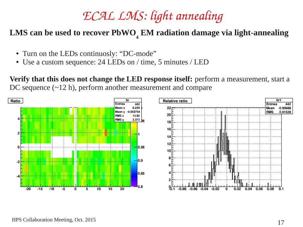
ECAL LMS: light annealingLMS can be used to recover PbWO
4 EM radiation damage via light-annealing
● Turn on the LEDs continuosly: “DC-mode”● Use a custom sequence: 24 LEDs on / time, 5 minutes / LED
Verify that this does not change the LED response itself: perform a measurement, start a DC sequence (~12 h), perform another measurement and compare
●

HPS Collaboration Meeting, Oct. 2015
18
Conclusions● The Led Monitoring System is installed in HPS and is fully operational
● The system has extensively been used during the Enginerring Run● Ecal Commissioning● Trigger Commissioning
● Further work is necessary to use it to measure Ecal long-term stability (radiation damage)● Complete the integration of the sequence analysis in the online monitoring
system and in the conditions system● Compare offline and online results● Conclude the analysis of Engineering Run measurements