eca generator lami-200 user manual - aquacentrum.de
TRANSCRIPT

ECA Generator
LAMI-200
USER MANUAL
revision date description
Inline pH sensor
Inline ORP sensor
Full automatic flushing
01 ● Internet
02 ● pH control by PLC
02 ● Manual valves electronic position control
Kirkmayer Industries OÜ - Tööstuse tn 86 Tallinn - 10416 Harju maakond - Estonia T +372 5563 8827 | email: [email protected] | www.kirkmayer.com

ECA Generator | LAMI-200 Document: USER MANUAL
1. SUMMARY
02 05.02.2020 first release
1. SUMMARY 2 ...........................................................................................2. SAFETY INFORMATION 3 .............................................................................3. CONTACTS AND TECHNICAL SERVICES 3 .........................................................4. SYSTEM DESCRIPTION 4 .............................................................................
4.1. General requirements 5 .......................................................................4.2. Controls and connectors - electrical enclosure 6 ..........................................4.3. Controls and connectors - hydraulic enclosure 9 ..........................................4.4. Hydraulic components 10 .....................................................................
5. INSTALLATION 12 .....................................................................................5.1. Installation location 12 ........................................................................5.2. Mounting surface 12 ............................................................................5.3. Preparation of saturated saline (NaCl) solution 12 ........................................5.4. Typical installation layout 14 .................................................................5.5. Advised installation requirements 14 .......................................................5.6. Preliminary operations 14 .....................................................................
6. OPERATION 18 ........................................................................................6.1. Control data reader PLC 18 ..................................................................6.2. Cell flushing instructions 21 ..................................................................
7. MAINTENANCE 26 ....................................................................................7.1. Daily Maintenance 26 ..........................................................................7.2. Weekly Maintenance 26 ........................................................................7.3. Monthly Maintenance (depending on hardness of the water) 27 ........................7.4. Maintenance on pump 27 ......................................................................
8. TROUBLESHOOTING 28 ..............................................................................9. OPTIONAL INFORMATIONS 29 .......................................................................
9.1. Statistics 29 .....................................................................................9.2. Alarm records 29 ...............................................................................9.3. Extended information 29 ......................................................................
10.Network setup 30....................................................................................
page 2

ECA Generator | LAMI-200 Document: USER MANUAL
2. SAFETY INFORMATION
Caution The installation site must be undercover! Ensure that the enclosure is not affected by the atmospheric conditions. Unit with electronics is only suitable for indoor use! Do not install outdoors!
Qualification and training of personnel The personnel responsible for the operation, maintenance, inspection, and installation must be appropriately qualified for these tasks. The operator must precisely define areas of responsibility, levels of authority, and the supervision of the personnel. If the personnel does not have the necessary knowledge, the training and instruction needed must be given. If necessary, training can be performed by the manufacturer/supplier at the request of the operator of the unit. It is the responsibility of the operator to make sure that the personnel understands the contents of the unit's manual.
Safety-conscious working The safety instructions in this manual, applicable national health and safety regulations, and any internal operator working, operating, and safety regulations must be observed. Safety instructions for the operator/user. Hazardous hot or cold parts of the unit must be protected to prevent accidental contact. Leakages of Anolyte or Catholyte must be disposed of in a way that is not harmful to the personnel or the environment. Legal regulations must be observed. Damage caused by electrical energy must be prevented (for more details, see, for example, the regulations of the VDE and the local electricity supply company).
Unauthorized modification and manufacture of spare parts Modification or changes to the unit are only permitted following agreement with the manufacturer. Original spare parts and accessories authorized by the manufacturer are safe to use. Using other parts can result in liability for any resulting consequences.
3. CONTACTS AND TECHNICAL SERVICES
• email: [email protected]
page 3

ECA Generator | LAMI-200 Document: USER MANUAL
4. SYSTEM DESCRIPTION
Thank you for purchasing Kirkmayer’s generator. This unit is based on the ECA technology developed by Kirkmayer Industries Ltd. for on-site generation of 200 LPH Anolyte solution with 500 ppm FAC (Free Available Chlorine) out of NaCl brine, 12 hours per day (fixed-parameter). Before using this unit, read this user manual carefully to obtain the best results and ensuring safety & health measures. Not following the prescriptions contained in this manual will be considered improper use.
General Description The system produces a liquid disinfectant, non-toxic and degradable, capable of destroying bacteria, spores, viruses, molds, yeasts, fungi, biofilms (biological incrustations) on pipes, and removing odors. Its operation requires only water, Sodium or Potassium Chloride (salt), and electricity. Based on an electrolysis process, consisting in passing through a high purity saline solution with pre-defined and controlled amperage and voltage values, the system produce different types of aqueous solutions that can be directly used as disinfectants in diluted form, injected into the liquid to be treated or nebulized with extreme adaptability to the different operating conditions and complete absence of toxicity for humans and the environment.
The main benefits include low costs, the versatility of use, easy to install (no need to modify any existing system), proven effectiveness, and the absence of problems that we can find in the traditional treatments such as chlorination and UV radiation.
Our patent-pending systems have been successfully applied for the disinfection of sewage, industrial water (food industries), swimming pools, farms, agriculture, and the removal of pollutants from industrial, urban wastewater, and other numerous applications.
As presented in several scientific publications, multicellular organisms, including human beings and hot blooded mammals that must defend themselves against pathogens and a variety of foreign microorganisms, are able to synthesize complex mixtures of metastable oxidizing compounds through metabolism.
Such compounds possess a broad spectrum of actions capable of damaging all major systemic groups of pathogenic microorganisms (bacteria, mycobacteria, viruses, moulds, spores, etc.) with no damage to multicellular organisms or human tissues. The oxidizing liquids and their chemical production mechanisms are similar to those generated in our ECA system. These characteristics give Anolyte a high biocompatibility
page 4

ECA Generator | LAMI-200 Document: USER MANUAL
with human tissues and multicellular organisms. Further, the compounds we use are eco-friendly and not toxic to the environment, or living creatures.
4.1. General requirements
Power source • Power supply for AC voltage • Rated voltage range: 230 VAC / 8A • Deviation from the rated value: ± 10 % • Mains frequency: 50/60 Hz • Maximum input power: 1.5 kW including all sensors
Ambient and operating conditions • Permissible ambient temperature: 0 °C to +50 °C. • Permissible storage temperature: 0 °C to +50 °C. • Permissible air humidity: max. relative humidity: 92 % (non-condensing)
Mains water basic characteristics • preferably tap water • preferably soft or softened water • filtered water
Operating condition Input water: maximum system pressure is 2.0 - 2.5 bar. The system water for the unit needs to be filtered to ~50 microns prior to the input, and pulses/water hammer effects should be minimized to prevent unit damage. Optimal suction lift (start-up) for brine media is ~1.00 mt.
page 5

ECA Generator | LAMI-200 Document: USER MANUAL
4.2. Controls and connectors - electrical enclosure
External panels 1. Mains power cord 2. Ethernet RJ45 socket
page 6
2
1
Cooling fan

ECA Generator | LAMI-200 Document: USER MANUAL
3. Main power LED 4. Alarm LED 5. Stand by LED 6. Generating LED 7. Emergency switch 8. Power switch 9. Unitronics PLC
page 7
9
6543
7
8

ECA Generator | LAMI-200 Document: USER MANUAL
10. Circuit breaker
page 8
10

ECA Generator | LAMI-200 Document: USER MANUAL
4.3. Controls and connectors - hydraulic enclosure
1. Anolyte outlet - 1/2” 2. Catholyte outlet – 3/8” 3. Level sensor socket 4. Drain – 3/8” 5. Acid inlet – 1/4” 6. Acid out – 3/8” 7. Brine inlet – 1/4” 8. Water inlet – 3/8”
page 9
1
2
3
6
5
7
4
8

ECA Generator | LAMI-200 Document: USER MANUAL
8. Manual valves V1-V6
4.4. Hydraulic components
page 10
V1
V2V3
V4
V5V6

ECA Generator | LAMI-200 Document: USER MANUAL
1. Electrolysis cell 2. Pressure sensor 3. Water input elctro valve 4. Flow sensor 5. Rectifier cooler 6. Brine pump 7. pH control pump 8. Brine sensor 9. Acid flushing pump 10.Venturi pump 11.Process water filter 12.Water flushing electro valve
page 11
234
65
7
8
9
10
1
11
12

ECA Generator | LAMI-200 Document: USER MANUAL
5. INSTALLATION
5.1. Installation location
• Space required for operation and maintenance • The control elements must be easily accessible during operation • Provide sufficient space for operation and maintenance
5.2. Mounting surface
The unit must be mounted on a flat wall surface.
5.3. Preparation of saturated saline (NaCl) solution
Salt purity. The electrolyzer uses aqueous solutions of NaCl to produce Anolyte and Catholyte. To prevent the diaphragm from rapid plugging up, we advise using NaCl with the highest purity. The ECA-diaphragm is designed to allow cations, in particular, sodium ions to pass through. Using salts with a substantial amount of other cations (e.g., magnesium or calcium), that could be in the salt will result in extra cleaning of the membrane, and it will eventually result in a reduced lifetime. The salt must be composed of 99.8-99.9% of sodium chloride (NaCl) and cannot contain any additives such as iodine or anticaking agents. Using the wrong salt can cause damage to the electrolysis cells. Salt must conform to EN 973, grade A standard. In case salt does not comply standard, then brine must be prepared using Anolyte to oxidize side products in salt; this will avoid oxidation in electrolysis cell, set external sediment filter 50micron before unit intake.
Preparation of saturated saline (NaCl) solution The use of salt hopper is advised to prepare the brine. A salt hopper ensures that the saline solution is always of the same quality. The saline solution is always fully saturated, and different dilutions of the saline solution are avoided. In a salt hopper, the saline-solution for the unit is pumped from the bottom of the container, whereas a thick layer (>25cm) of NaCl is placed on a permeable mesh. This holds the salt above the bottom of the container, allows water to pass through the mesh. The water that passes the salt layer is fully saturated. Depending on the capacity of the salt hopper, the operator only has periodically to fill the container with softened/filtered water and NaCl. Please ask your distributor for the drawing of one of the possible designs of the salt hopper.
page 12

ECA Generator | LAMI-200 Document: USER MANUAL
Manual preparation of 100 liters saline-solution. • In case no salt hopper is available, the operator has to prepare and monitor the
saline solution before and during the production of activated solutions. • Using unsaturated saline solution can result in shutdowns of the unit. • Fill up a container with 80 liters of softened/filtered water. • Weigh 25-kg salt. • Add the 25-kg salt to the 100-liter container. • Mix the solution in the container until the salt is completely dissolved. • Mix the brine during the generation of activated solutions to ensure equal quality. • Sink to the bottom brine filter in brine tank; fix brine hose to avoid it float up.
NOTE To obtain the best performances and extend the life of the generator, we recommend using the highest quality sodium chloride (standard EN 973), softened water at zero French degrees, salt hopper. Is advised to add 10% of Anolyte in the brine tank to avoid oxidation of side salt products in electrolysis cell, set external sediment filter 50 microns before unit intake.
page 13

ECA Generator | LAMI-200 Document: USER MANUAL
5.4. Typical installation layout
5.5. Advised installation requirements
• Install a manual valve before the unit in the mains water supply to close all water to the unit
• Install a simple water filter to avoid deposits within the unit. (~20-50 Microns or so) • Install a pressure controller to set the right mains water pressure ~2.0-2.5 bars • Use always a salt filter to prevent the NaCl-particles from blocking the tubing inside
the unit, supplied with the unit • Ensure that ventilation in the room is sufficient. • Make one person responsible for operating the unit or provide traceability of
operators • Have at all-time safety & health instructions available for the operator
5.6. Preliminary operations
• Unpack the unit and ensure that all parts as per the packing list are present and undamaged
• Locate the unit adjacent to a power and water supply in a safe and secure position, in a well-ventilated area
• Check all valves inside the hydraulic cabinet and make sure they all in a position as indicated the table above or Operation mode
page 14

ECA Generator | LAMI-200 Document: USER MANUAL
• Check all power connections if they might have gone loose during transportation. Tighten them up
• Ensure containers are available for holding the salt solution (salt hopper) and the Anolyte
• These containers should ideally be sited next to the unit and made of industrial plastic
• Ensure that pressure of the water supply is maximum ~2.0 - 2.5 bar and volume (LPH) is what needed for the unit (200 LPH)
• Connect water-input tube to the marked input connector • Connect brine input tube to the input connector • Connect Anolyte and Catholyte output tubes to the marked output connectors • Insert ANK-Anolyte into the container. Direct Catholyte hose to drain or Catholyte
collecting tank • Check what manual “Winter valve” V3 is set depends on season. In winter, when
input water temperature below 10Cᵒ suggested close V3 valve and in summer when input water temperature over 10Cᵒ suggested open V3 valve. NB! Never install any valves on the unit outputs lines. Maximum output hose length is 4 meter, avoid sharp angles, maximum hose height 1 meter above unit top
• Check what all manual valves V1-V6 set in operating positions. See table and picture below:
• NB! Wrong set of valves can provoke cell membrane damage.
Valve Position
V1 Open
V2 Open
V3Depend of water
tᵒ
V4 Close
V5 Close
V6 Close
page 15
“Winter valve” V3

ECA Generator | LAMI-200 Document: USER MANUAL
Prepare the salt solution, which for standard applications should be a >25% NaCl solution (see instructions above). • Immerse the salt pickup (incl. salt pickup filter) into the bottom of the prepared
brine solution tank • Ensure that all switches are switched on • Check once again if all plugs are connected to the right sockets • Check if tubes are properly fitted • Check the emergency switch to be in a Ready to use position (Pullout) • Check Circuit breaker inside the unit in ON position. See the picture below:
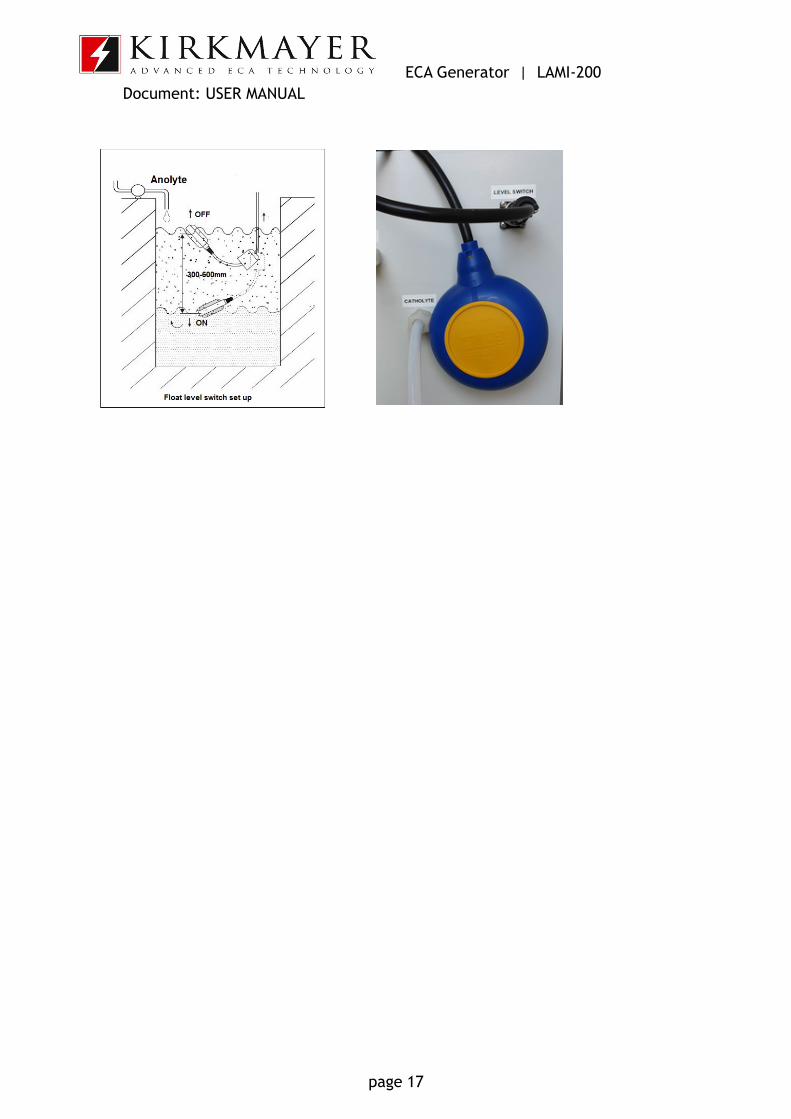
• Connect the power cable to a 230 volts AC/ 1 phase power socket • Switch on the main power switch • With the power ON you will be in the main menu of the PLC • Install Level switch in Anolyte container. (See the picture below)
NOTE. Anolyte output hose must be fixed at the top of Anolyte collecting tank and not submerged, Anolyte will flow free falling, this prevents back pressure to unit cell (back pressure can damage the ceramic membrane) NOTE. Catholyte output hose must be fixed at the top of Catholyte collecting tank or drain and not submerged, Catholyte will flow free falling, this prevents back pressure to unit cell (back pressure can damage the ceramic membrane)
page 16
ECA Generator | LAMI-200 Document: USER MANUAL
page 17

ECA Generator | LAMI-200 Document: USER MANUAL
6. OPERATION
6.1. Control data reader PLC
By using this PLC, the operator can have the following readings:
Operation – main screen • mains flow • salt consumption • working current • mains water pressure • status of Anolyte tank: full or empty • FAC set • pH set • status of the unit: working mode, standby or flushing (alarm signal) • standby reason
Flushing mode • activation flushing • getting back to main screen and resuming operation
Diagnostics of the problems • inadequate mains water flow and pressure • brine pump problem • mains flow switch problem • brine saturation, salt consumption • any of the RCDs tripping off • inadequate working current • Anolyte tank status • Valves position
Statistic data • Alarms record • Generating time • Water consumption
1. For first commissioning, to fill with water the electrolysis cell’s chambers, will take around 1 minute:
page 18

ECA Generator | LAMI-200 Document: USER MANUAL
2. Check that tank condition show empty and pressure OK then touch “Start” button
3. After start set the flow to 205 LPH using V1 valve or adjust pressure regulator (preferred)
4. Check what brine pump starts sucking brine In case of brine, not sucks check what brine input hose fitting firmly tighten, check what air not penetrates in brine line. PLC automatically adjusts pumps and work current, and this procedure can take ~10min.
To change FAC or correct pH of Anolyte touch Setup button, then “Operation settings” from setup menu: Default factory password is [1]
table1 First commissioning, check that valves are set in work position
Valve Position V1 Open V2 Open
V3 Depend of water tᵒ
V4 Close V5 Close V6 Close
page 19

ECA Generator | LAMI-200 Document: USER MANUAL
After changing desired pH or FAC, touch Return button to return to main screen.
NOTE Changing the Anolyte’s parameters, takes about 5-10 minutes.
To change the default password, touch Change password button and set a new password. Touch Return button to return to the main screen.
page 20

ECA Generator | LAMI-200 Document: USER MANUAL
6.2. Cell flushing instructions
Periodically the cell(s) in the unit needs to be flushed as the hardness of water will result in deposits on the electrodes and diaphragm. As the hardness of water varies all over the world, it isn't straightforward to say how many times the unit should be flushed. Usually, if source water has 0° French degree of hardness, the flushing interval is once every 2-3 months. The necessity for flushing is controlled by the PLC and will be indicated on the display when the need arises. Also, the flushing interval can be set to interval timer. Flushing advice mode can be set from “Operation settings” / “Flushing setup” menu.
page 21

ECA Generator | LAMI-200 Document: USER MANUAL
If flushing set to interval timer, PLC will be indicated when timer finish and advices flush cell. Chemicals / Materials needed:
• Hydrochloric acid (HCl) (~10%) 4-5 L Container/jug • In case you have 30% of HCl acid, it must be diluted with water. To dilute 30% HCl
acid, add 1L of 30% of HCl acid, into 2L of water. NB! In dilution process always add acid in water to prevent acid splash, use eyes protection glasses
The procedure is as follows: 1. Stop unit 2. Have all valves in flushing mode position according to the table and picture below: • NB! Wrong set of valves can provoke cell membrane damage.
3. Touch “Flush” button on main PLC screen - flushing “Step 1” will appear:
Flushing Step 1 - Pre flush cell with water
Shut off valves can be set in two position open or close
Open position Close position
page 22

ECA Generator | LAMI-200 Document: USER MANUAL
4. Connect Drain hose and direct into drain 5. Touch Switch I-0 button to start 6. This cycle is set for 10 min. Touch Switch I-0 button to terminate this procedure
earlier 7. After Step 1 timer finish close V5 valve 8. Press “→” to enter “Step 2”:
NOTE. Acid input hose must be fixed in the acid jug and submerged in acid. The terminal of the hose must be set in the middle of the tank’s liquid height to avoid pickup deposit from the bottom of the jug and send to the acid pump. Acid out hose must be fixed in the acid jug at the top of the jug.
page 23

ECA Generator | LAMI-200 Document: USER MANUAL
Flushing Step 2 – Flush cell with acid
9. Have all valves in flushing mode position according to the table and picture 10.Connect the acid hose to the Acid in and immerse it into the container with 5L of
10% HCl acid 11.Connect Acid out hose and direct into the container with acid 12.Open V4, V6 valve 13.Touch Switch I-0 button to start acid pump 14.This cycle is set for 50 min. Touch Switch I-0 button to terminate this procedure
earlier 15.Check what during this procedure acid go out from drain hose to be sure what acid is
circulated
page 24

ECA Generator | LAMI-200 Document: USER MANUAL
16.After timer finish close V4,V6 valves 17.Press “→” to enter “Step 3”
Flushing Step 3 - Post flush cell and acid pump with water
18.Have all valves in flushing mode position according to the table and picture 19.Connect Drain hose and direct it to drain 20.Touch Switch I-0 button to start the acid pump
page 25

ECA Generator | LAMI-200 Document: USER MANUAL
21.This cycle is set for 10 min. Touch Switch I-0 button to terminate this procedure earlier
22.After timer finish close V5 valve 23.Press “→” to enter “Step 4”:
Flushing Step 4 – Set valves in operating mode
24.Have all valves in operating mode position according to the table and image below:
NB! Check what V4, V5, V6 valves closed completely.
25.Push arrow up button to return main screen
7. MAINTENANCE
7.1. Daily Maintenance
• Check if the volume of NaCl in the brine container is adequate for the output required for that day
• Check the generator to see if there are any obvious problems, i.e., leakages • Check the flow indicator for adequate flow through the generator • Check if the current meter indicates the working current according to the setting
7.2. Weekly Maintenance
• Carry out the daily maintenance schedule
page 26

ECA Generator | LAMI-200 Document: USER MANUAL
• Check Anolyte quality measuring pH, ORP, and active chlorine of freshly generated Anolyte. Take a sample from Anolyte container
7.3. Monthly Maintenance (depending on hardness of the water)
• Carry out weekly maintenance • Carry out cell flushing procedures • Check all power connections if they might have gone loose. Tighten them up.
Clean them from rust as well, if any • Check water filters, clean up or replace them depending on the condition
7.4. Maintenance on pump
• Check input filters every 1.000 hours, clean it’s using water • Check not air penetrates in input line tight connectors • Check brine pickup filter cleanup it with water
page 27

ECA Generator | LAMI-200 Document: USER MANUAL
8. TROUBLESHOOTING
What may appear to be the trouble is not always a real problem. Re-start the unit a couple of times. See if it helps. If not, you can read all the issues which might influence the smooth performance of the unit, such as low pressure/flow of the mains water, low quality of brine, etc. on the PLC. React accordingly. This appliance is manufactured to conform to the European Machinery Directive (2006/42/EEC) and is designed to comply with the requirements of the following EEC Directives:
• European Machinery Directive (2006/42/EEC) • E.M.C Emissions Testing (EN55022) • E.M.C Generic Immunity Testing (EN 50082-1) • CE Marking LVD Directive (93/68/EEC) • Electro Magnetic Compatibility Directive (2004/108/EEC)
• ECHA (European Chemical Agency – the responsible authority for the BPR) INCLUDED KIRKMAYER INDUSTRIES OÜ, IN THE LIST OF ACTIVE SUBSTANCES AND SUPPLIERS (Article 95 list) UNDER ARTICLE 95(1) REGULATION (EU) No 528/2012.
• Decision number: ACC-D-1363343-55-00/F
page 28

ECA Generator | LAMI-200 Document: USER MANUAL
9. OPTIONAL INFORMATIONS
9.1. Statistics
9.2. Alarm records
9.3. Extended information
page 29

ECA Generator | LAMI-200 Document: USER MANUAL
10.Network setup
To set up the network: Connect network cable into the network socket on the unit. Ask from the local network administrator or your Internet provider for the available IP address, subnet mask, default gateway, and available ports. If the unit needs remote access outside of local the network, then the Internet router must set to port forwarding to PLC IP address. PLC supports 2 ports; it means that when 2 ports set, then 2 PC or PC and smartphone can connect to PLC simultaneously. If only one port set, then only one PC or smartphone can connect to PLC at the time. Press name button and type desired PLC network name 8 characters max. PLC network name also works as a network PLC access password. After setup, all network parameters press PLC restart button to reload it with new settings. To connect and remote unit from PC two programs, can be used:
1. Remote Access V9.8.10 View and control a PLC directly from PC, via local or remote connection: download link - https://unitronicsplc.com/Download/SoftwareUtilities/RemoteAccess_9_8_10.exe 2. Remote Operator V1.0.71 Simultaneously view and operate the HMI panels of multiple PLCs in multiple locations: download link - https://unitronicsplc.com/Download/SoftwareUtilities/Remote%20Operator%20Version%201.0.71.zip 3. For Android smartphone look Unitronics’ Remote Operator in Google play Link - https://play.google.com/store/apps/details?id=com.unitronics.remoteoperator For Apple IOS smartphone look app store Unitronics' Remote Operator Link - https://itunes.apple.com/us/app/unitronics-remote-operator/id1063107386?mt=8
page 30