ec6501 digital communication - dce · a) in linear quantization, at low signal levels the signal to...
TRANSCRIPT

EC6501 Digital Communication V Semester
Department of Electronics and Communication Engineering 1
EC6501 Digital Communication
UNIT -1 DIGITAL COMMUNICATION SYSTEMS
Digital Communication system
1) Write the advantages and disadvantages of digital communication. [A/M – 11]
The advantages of digital communication are,
(a) Ruggedness to channel noise and external interference.
(b) Flexible operation of the system.
(c) Multiplexing of various sources of information into a common format.
(d) Security of information.
(e) Digital circuits are more reliable, lower cost than analog circuits.
(f) Errors may be corrected by the use of coding
The disadvantages of digital communication are,
(a) Digital Communication has completely ignored the human touch. A personal touch
cannot be established because all the computers will have the same font
(b) The establishment of Digital Communication causes degradation of the environment
in some cases. "Electronic waste" is an example
2) Which parameter is called figure of merit in a digital communication system? Why?
[N/D – 10]
The ratio Eb/No or bit energy to noise power spectral density is called figure of merit in
digital communication system.
Reasons:
(a) Energy is calculated for bit. Hence Eb/No allows us to compare different systems at bit level.
(b)Eb/No is also unit less as does S/N
(c)Bit energy (Eb) can be calculated easily for digital data
3) What is meant by distortion less transmission? [N/D – 10]
For distortion less transmission, the transfer function of the system is represented as
H (w) = K e -jɷto
K is the constant magnitude response ɷt
o is the linear phase shift.
The above transfer function imposes two requirements on the system.
1. The system response must have constant magnitude response
2. The system phase shift response must be linear with frequency

EC6501 Digital Communication V Semester
Department of Electronics and Communication Engineering 2
4) Define – Bit Error Rate [A/M – 12]
The bit error rate is defined as number of bits that are wrongly transmitted. It is normally given
as a probability of bit error. Because of distortion and interference over the channel, the signal is
corrupted and wrongly interpreted at the receiver.
PULSE MODULATION
5) Define – Pulse Amplitude Modulation [N/D – 08]
In pulse amplitude modulation the amplitude of the pulse is directly proportional to the
amplitude of modulating signal at the sampling rate. The width of the pulse remains constant.
6) How is PDM wave converted into PPM wave? [N/D – 08]
The PDM signal is given as clock signal to monostable multivibrator. The multivibrator triggers
on falling edge. Hence a PPM pulse of fixed width is produced after falling edge of PDM pulse. The
position of the PPM pulse depends upon input signal amplitude.
7) What are the drawbacks of PAM? [N/D – 07]
The drawbacks of PAM are:
(a) The bandwidth need for transmission of PAM signals is very large compared to is maximum
frequency content.
(b) The amplitude of PAM pulse varies according to modulating signal. Therefore interference
of noise is maximum for the PAM signal and this noise cannot be removed very easily.
(c) Since amplitude of PAM signal varies, the peak power required by the transmitter
is also varied.
8) Draw the functional block diagram of digital communication system. [N/D – 11]
Discrete
information
source
Source
Encoder
Channel
Encoder
Baseband
processor or
modulator
Electrical
communication
channel
Destination
Source
decoder
Channel
decoder
Baseband
decoder or
demodulator

EC6501 Digital Communication V Semester
Department of Electronics and Communication Engineering 3
9) Define – Half Power Bandwidth [N/D – 11]
The bandwidth where the PSD drops to half (3dB) of its maximum value is called half power
bandwidth. It is also called “ 3dB bandwidth ”.
10) What is GSOP? [N/D – 12]
GSOP (Gram Schmidt Orthogonalisation Procedure) is a tool to obtain certain parameters such
as
1) Orthogonal basis function.
2) Detection of dimensions of the signal (m, n).
11) Write the expression for the bandwidth of digital channel. [N/D – 11]
The expression for the bandwidth of the channel is
B =
B =
where,
N= Dimensions of the waveform in signal space.
T0= Time over which the waveform is described.
B= Bandwidth of the signal.
= symbol rate = N / T0.
12) Write an expression for linear filter channel? [N/D – 08]
The output of the channel is given by ,
R (t) = x(t)*h(t) + n(t)
where,
R (t) =output signal
h(t) = impulse response
x (t) = input signals
n(t) = noise signal.
13) Define – Pulse Position Modulation [N/D – 09]

EC6501 Digital Communication V Semester
Department of Electronics and Communication Engineering 4
The event at which “ the amplitude and width of the pulses are kept constant , with the position
of a reference pulse is changed in accordance to the instantaneous sampled value of the
modulating signal “ is known to be Pulse Position Modulation .
14) How the message can be recovered from PAM? [M/J – 08]
The message can be recovered from PAM by passing the PAM signal through reconstruction
filter. The reconstruction filter integrates amplitude of PAM pulses. Amplitude smoothing of the
reconstructed signal is done to remove amplitude discontinuities due to pulses.
15) What is the Euclidean distance between two signal vectors?[M/J – 09]
The Euclidean distance dik is the distance between the two signal vectors and it is represented as
dik = ||si-sk|| =
where si and sk are signal vectors
16) Define – Pulse Width Modulation [Noc /Dec 1997]
In pulse width modulation, the width of the pulse changes according to amplitude of the modulating
signal. It is also referred as pulse duration modulation.
17) State dimension theorem.
The dimensionality theorem states that, a real waveform can be completely specified by ’N’
independent pieces of information where N is given by,
N=2BTo
N- Dimension of the wave form in signal space
B-Bandwidth of the Signal
To- Time over which the waveform is described(period)
18) State the principal of PPM.
The amplitude and width of the pulses are kept constant, while the position of each pulse, with
reference to the position of a reference pulse is changed according to the instantaneous sampled
value of the modulating signal.
EC6501 Digital Communication V Semester
Department of Electronics and Communication Engineering 5
19) Write the application of Pulse Width Modulation.
The applications of Pulse Width Modulation are
a) PWM is used for asynchronous transmission over noise channel.
b) PWM is used to generate PPM.
c) It is also used in motor control application.
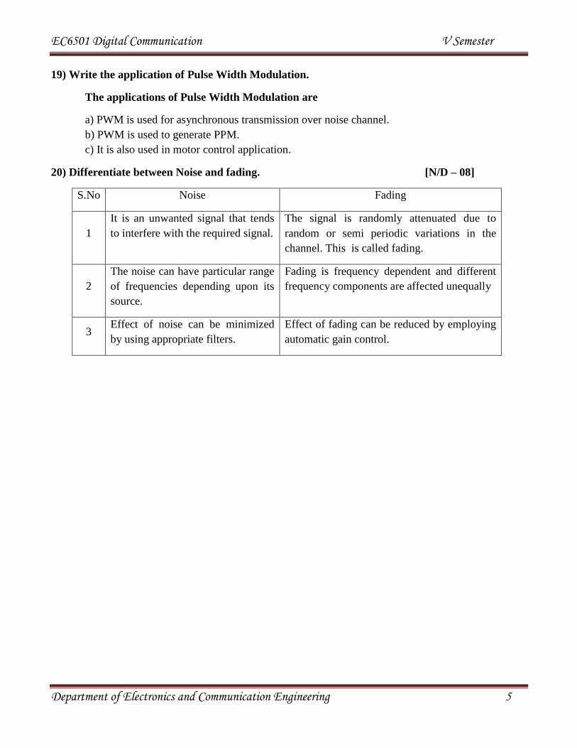
20) Differentiate between Noise and fading. [N/D – 08]
S.No Noise Fading
1
It is an unwanted signal that tends
to interfere with the required signal.
The signal is randomly attenuated due to
random or semi periodic variations in the
channel. This is called fading.
2
The noise can have particular range
of frequencies depending upon its
source.
Fading is frequency dependent and different
frequency components are affected unequally
3 Effect of noise can be minimized
by using appropriate filters.
Effect of fading can be reduced by employing
automatic gain control.

EC6501 Digital Communication V Semester
Department of Electronics and Communication Engineering 6
UNIT II
BASE BANDFORMATTING TECNIQUE
SAMPLING
1. State sampling theorem. [M/J – 11]
A band limited signal of finite energy, that has no frequency components higher than W
Hz is complete described by specifying the values of the signal at instants of time separated by
seconds.
2. What is mean by aliasing? [M/J – 11]
Aliasing effect takes place when sampling frequency is less than Nyquist rate. Under
such condition, the spectrum of the sampled signal overlaps with itself. Hence higher frequencies
take the form of lower frequencies. This interference of the frequency component is called
aliasing.
3. Why is prefiltering done before sampling? [N/D – 10]
The prefiltering is done before sampling because
i) The signal must be limited to some highest frequency ‘W’ Hz before sampling. Then the
signal is sampled at the frequency of fs = 2 W.
ii) The signal should be prefiltered (low pass filtered) to eliminate any frequency
components higher than ‘W’ Hz.
iii) If the signal is not prefiltered, then frequency components higher than ‘W’ Hz will
generate aliasing in the sampled signal spectrum.
4. State sampling theorem for low pass signals.
If a finite energy signal g(t) contains no frequencies higher than W hertz, it is completely
determined by specifying its co-ordinates at a sequence of points spaced seconds apart.
If a finite energy signal g(t) contains no frequencies higher than W hertz, it may be
completely recovered from its co-ordinates at a sequence of points spaced seconds apart.
5. A band pass signal has the signal range that extends from 20 KHz to 82 KHz. Find the
accepted range of sampling frequency fs. [N/D – 08]
Given data:
BW = 82 KHz - 20 KHz = 62 KHz
Solution:
fs = 2 × BW =2 × 62KHz =124KHz

EC6501 Digital Communication V Semester
Department of Electronics and Communication Engineering 7
6. State band pass sampling theorem. [M/J – 06] [M/J – 04]
The band pass signal X (t ) with maximum bandwidth of 2W can be completely
represented into frequency and recovered from its samples, if it is sampled at the maximum rate
of twice the bandwidth.
QUANTIZATION
7. Define - Quantization error [M/J – 07]
Quantization error is the difference between the output and input values of quantizer.
= Xq(nTs) – X(nTs)
Xq(nTs) is the quantized value of the signal.
X(nTs) is the value of the sampled bit.
8. Define - Quantization noise power [N/D – 10]
Quantization noise power is the noise power due to quantization noise. The quantization noise
has the probability density function of ft( ). Then quantization noise power is given as
E[2]=
ENCODING TECHNIQUES FOR ANALOG SOURCES
9. Why compressors are used in PCM? [N/D – 04]
Compressors are used in PCM because
a) In linear quantization, at low signal levels the signal to quantization noise ratio reduces.
b) Compression uses nonlinear quantization. It improves the signal to quantization noise ratio at
low level signals.
10. What is the SNR of PCM system if number of quantization level is 28?
[M/J – 06]
Given Data:
Quantization level = 2v
= 28
where v is the no. Of transmitted bit
v = 8
Solution:
(S/N)dB = 4.8 +6v db
(S/N)dB = 4.8 + 6 ×8 =52.8 dB
11. State the Principle of DPCM. [M/J – 08]
EC6501 Digital Communication V Semester
Department of Electronics and Communication Engineering 8
The principle of DPCM is, it sends the information about difference between actual
sample value and predicated sample value.
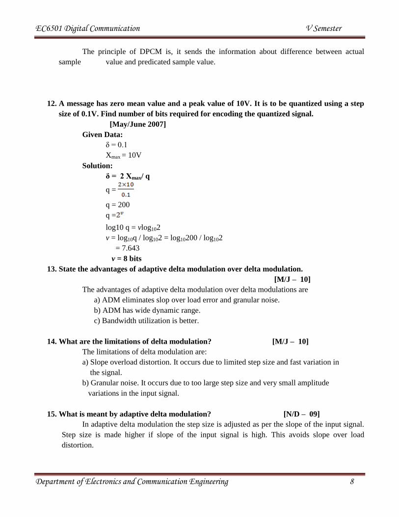
12. A message has zero mean value and a peak value of 10V. It is to be quantized using a step
size of 0.1V. Find number of bits required for encoding the quantized signal.
[May/June 2007]
Given Data:
δ = 0.1
Xmax = 10V
Solution:
δ = 2 Xmax/ q
q =
q = 200
q =
log10 q = vlog102
v = log10q / log102 = log10200 / log102
= 7.643
v = 8 bits
13. State the advantages of adaptive delta modulation over delta modulation.
[M/J – 10]
The advantages of adaptive delta modulation over delta modulations are
a) ADM eliminates slop over load error and granular noise.
b) ADM has wide dynamic range.
c) Bandwidth utilization is better.
14. What are the limitations of delta modulation? [M/J – 10]
The limitations of delta modulation are:
a) Slope overload distortion. It occurs due to limited step size and fast variation in
the signal.
b) Granular noise. It occurs due to too large step size and very small amplitude
variations in the input signal.
15. What is meant by adaptive delta modulation? [N/D – 09]
In adaptive delta modulation the step size is adjusted as per the slope of the input signal.
Step size is made higher if slope of the input signal is high. This avoids slope over load
distortion.
EC6501 Digital Communication V Semester
Department of Electronics and Communication Engineering 9
16. What is the need for non uniform quantization of speech signal. [M/J – 08]
Speech and music signals are characterized by large crest factor. For such signals the
ratio of peak to rms value is very high. So non uniform quantization of varying step size is
required.
17. What is the meant by companding? [M/J – 08]
The compression of signal at transmitter and expansion of the compressed signal at the
receiver is called companding.
18. List the merits of DPCM. [N/D – 98]
Merits of DPCM are
a) Bandwidth requirements of DPCM is less compared PCM.
b) Quantization error is reduced because of prediction filter.
c) Numbers of bits used to represent one sample value are also reduced compared to
PCM.
19. What is Nyquist rate? [N/D – 97]
Let the signal be band limited to ‘W’ Hz. Then Nyquist rate is given as,
Nyquist rate = 2W samples/ sec
Aliasing will not take place if sampling rate is greater than Nyquist rate.
20. What is the required passband for antialiasing and smoothing filters used with pulse
modulation/ demodulation systems? [N/D – 04]
a) Antialiasing filter is used before sampling. It should band limit the signal to maximum
signal frequency of ‘W’ Hz. Hence its passband should be ‘W’ Hz.
b) Smoothing filter is used after reconstruction or interpolation. It should pass all the
frequencies of ‘0’ to ‘W’ Hz and block frequencies greater than ‘W’ Hz.
21. Differentiate DPCM from DM. [N/D – 98]
DM encodes the input sample by only one bit. It sends the information about +δ or -δ, i.e
step rise or fall.
DPCM can have more than one bit for encoding the sample. It sends the information
about difference between actual sample value and predicted sample value
EC6501 Digital Communication V Semester
Department of Electronics and Communication Engineering 10
UNIT-III BASEBAND CODING TECHNIQUES
Linear Block Codes
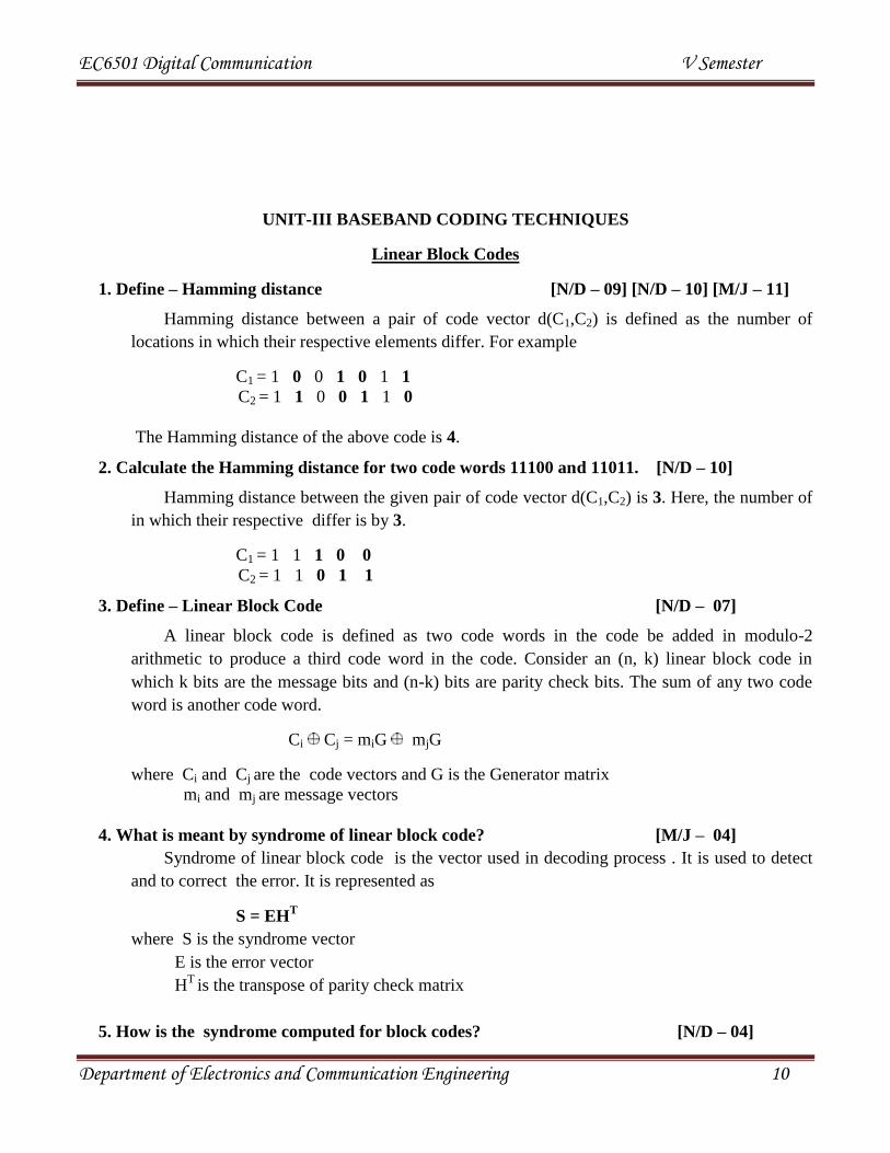
1. Define – Hamming distance [N/D – 09] [N/D – 10] [M/J – 11]
Hamming distance between a pair of code vector d(C1,C2) is defined as the number of
locations in which their respective elements differ. For example
C1 = 1 0 0 1 0 1 1
C2 = 1 1 0 0 1 1 0
The Hamming distance of the above code is 4.
2. Calculate the Hamming distance for two code words 11100 and 11011. [N/D – 10]
Hamming distance between the given pair of code vector d(C1,C2) is 3. Here, the number of
in which their respective differ is by 3.
C1 = 1 1 1 0 0
C2 = 1 1 0 1 1
3. Define – Linear Block Code [N/D – 07]
A linear block code is defined as two code words in the code be added in modulo-2
arithmetic to produce a third code word in the code. Consider an (n, k) linear block code in
which k bits are the message bits and (n-k) bits are parity check bits. The sum of any two code
word is another code word.
Ci Cj = miG mjG
where Ci and Cj are the code vectors and G is the Generator matrix
mi and mj are message vectors
4. What is meant by syndrome of linear block code? [M/J – 04]
Syndrome of linear block code is the vector used in decoding process . It is used to detect
and to correct the error. It is represented as
S = EHT
where S is the syndrome vector
E is the error vector
HT
is the transpose of parity check matrix
5. How is the syndrome computed for block codes? [N/D – 04]
EC6501 Digital Communication V Semester
Department of Electronics and Communication Engineering 11
In block codes the syndrome is calculated using
S = YHT
where, Y is the received vector
HT
is the transpose of parity check matrix
6. List the features of linear block codes. [M/J – 08]
The features of linear block codes are
1. The sum of two codeword’s is also a codeword belonging to the code.
2. The zero word is always a codeword.
3. The minimum distance between two code words of a linear code is equal to the minimum
weight of the code.
7. What are the steps involved in the decoding procedure of linear block code?
[N/D – 04] The steps involved in the decoding procedure of linear block code are
1. For the received vector Y, compute the syndrome S= YH.
2. Within the co-set characterized by the syndrome S, choose error pattern with the
largest probability as e0.
3. For output, compute the code vector X=Y+ e0.
8. Write the syndrome properties of linear block code.
The properties of syndrome are
Property 1: The syndrome depends only on the error pattern and not on the transmitted
code.
Property 2: All error pattern that differ by a code word have the same syndrome.
9. Define - Hamming codes
Hamming codes are of (n, k) linear block codes .A linear block code is defined as two code
words in the code be added in modulo-2 arithmetic to produce a third code word in the code.
10. Write the property of the Hamming codes.
The property of the Hamming codes
Hamming codes are of (n, k) linear block codes that have the following properties.
Block length = 2m
– 1
Number of message bits, k = 2m
– m - 1
Minimum distance, dmin= 3
EC6501 Digital Communication V Semester
Department of Electronics and Communication Engineering 12
No. of errors that can be corrected, t=1
11. Define – Minimum distance [M/J – 07]
The minimum distance dmin is defined as the smallest Hamming distance between any pair of
code vectors in the code. It determines the error correcting capability of the code.
dmin ≥ 2t + 1
where‘t’ is the no. of bits that can be corrected.
CONVOLUTIONAL CODES
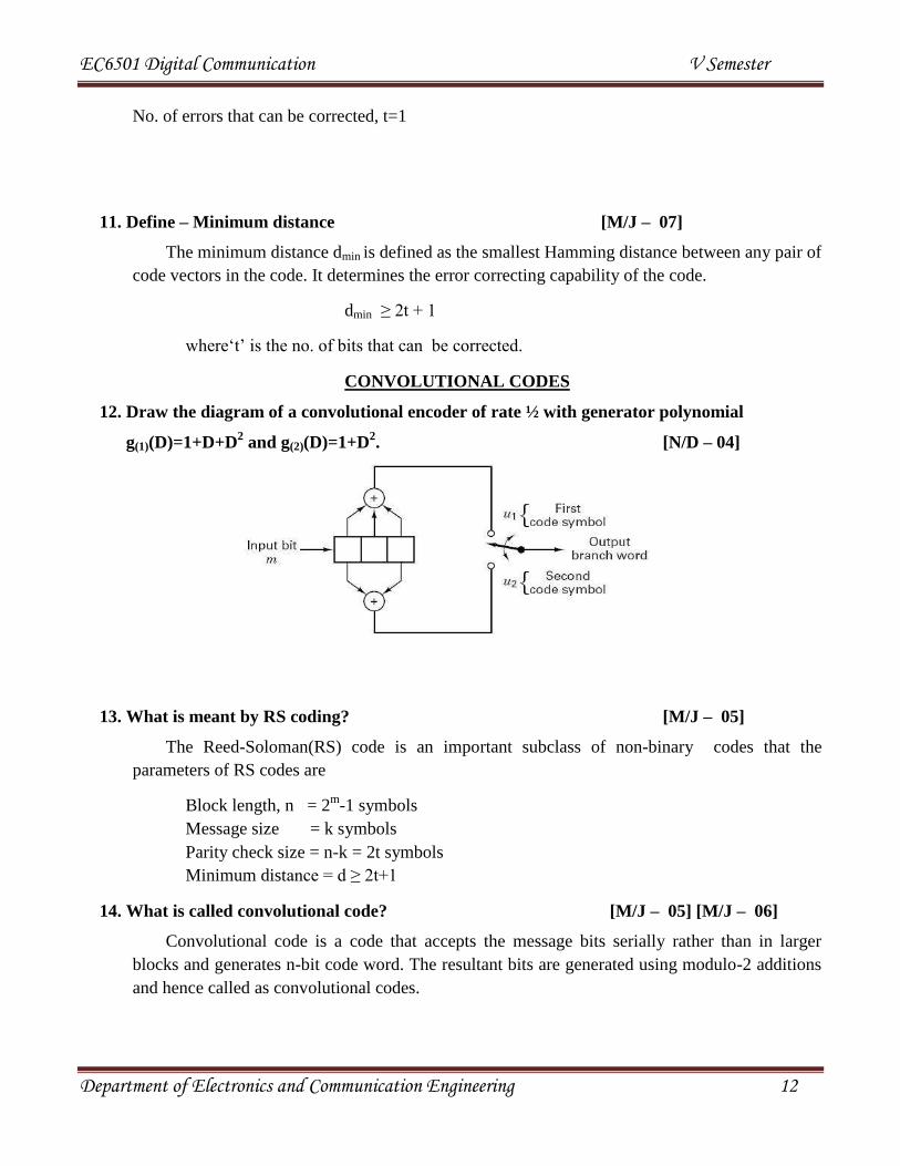
12. Draw the diagram of a convolutional encoder of rate ½ with generator polynomial
g(1)(D)=1+D+D2 and g(2)(D)=1+D
2. [N/D – 04]
13. What is meant by RS coding? [M/J – 05]
The Reed-Soloman(RS) code is an important subclass of non-binary codes that the
parameters of RS codes are
Block length, n = 2m
-1 symbols
Message size = k symbols
Parity check size = n-k = 2t symbols
Minimum distance = d ≥ 2t+1
14. What is called convolutional code? [M/J – 05] [M/J – 06]
Convolutional code is a code that accepts the message bits serially rather than in larger
blocks and generates n-bit code word. The resultant bits are generated using modulo-2 additions
and hence called as convolutional codes.

EC6501 Digital Communication V Semester
Department of Electronics and Communication Engineering 13
15. Differentiate block codes from convolutional codes. [N/D – 05] [M/J – 09]
Block Codes Convolutional codes
The block code accepts a k-bit message
block and generates a n-bit code word.
Thus, code words are produced on a
block-by-block basis.
The convolutional code accepts the
message bits serially rather than in larger
blocks and generates n-bit code word. The
resultant bits are generated using modulo-2
additions.
16. What is coding gain with reference to error control codes? [N/D – 05]
Coding gain is used as a basis for comparison of different coding methods. To achieve
the same bit error rate the coding gain is defined as
A =
where Eb is bit energy
N0 is the noise spectral density
17. What is meant by BCH code? [M/J – 06] [N/D – 07]
Bose-Chaudhuri-Hocquenhem codes are most extensive and powerful error correcting
cyclic codes. It can detect and correct upto ‘t’ random error per code word. For any positive
integer m≥3 and t ≤ 2m
-1 there exists a binary BCH code with following parameters.
Block length n = 2m
-1 symbols
Message size k ≥ n- mt
Minimum distance d ≥ 2t+1
18. What is meant by constraint length of convolutional code? [N/D – 07]
The number of shifts over which a single bit can influence the encoder output is called
constraint length and is given as
k= M + 1
where k is the constraint length

EC6501 Digital Communication V Semester
Department of Electronics and Communication Engineering 14
M is the no. of shift registers
19. What is Viterbi decoding scheme?
a. Viterbi decoding scheme performs maximum likelihood decoding
b. It reduces the computational load by taking advantage in code trellis..
c. It computes a metric for every possible path in the trellis and retains the lower metric
path.
20. What are the limitations of Viterbi decoding?
The limitations of Viterbi decoding are
a. It can correct up to 2 errors. A triple error pattern is uncorrectable by the Viterbi algorithm.
b. As the constraint length increases, complexity also increases exponentially.
Cyclic Codes
21. Define – Hamming weight [M/J – 09]
Hamming weight W(c) is defined as the number of non-zero elements in the code vector.
For example in the code vector 1001011 the Hamming weight is 4.
22. What are the fundamental properties exhibited by cyclic codes? [M/J – 09]
The fundamental properties exhibited by cyclic codes are
a. Linearity property is the sum of any two code words in the code is also a code word.
b. Cyclic Property is any cyclic shift of a code word in the code is also a code word.
23. Define - Coding efficiency
Coding efficiency or code rate is defined as the ratio of number of message bits in a block to
the number of transmitted bits for the block.
Coding efficiency or code rate = k/n
where, k is the number of message bits in a block
n is the number of transmitted bits for the block
24. What are the advantages of cyclic code?
Advantages of cyclic codes are
1. The error detection and decoding methods of cyclic codes are simpler and easy to
implement.
2. The encoders and decoders are simpler than that used for non-cyclic codes.

EC6501 Digital Communication V Semester
Department of Electronics and Communication Engineering 15
3. Cyclic codes have well defined mathematical structures. Hence, it is an efficient and
powerful code to detect burst errors.
25. What are the disadvantages of cyclic code?
The disadvantages of cyclic codes are:
1. The error detection is simple but error correction is little complicated.
2. Harder to design.
LINE CODES
26. What is meant by transparency with respect to line codes? [M/J – 11]
Transparency means a line code should be designed in such a way that the receiver does not
go out of synchronization for any sequence of data symbols. A code is not transparent if for some
sequence of symbols, the clock is lost.
27. Draw the NRZ and RZ codes for the digital data 11011000100. [N/D – 10]
A Non-Return-to-Zero (NRZ) line code is a binary code in which 1’s are represented by a
positive voltage and 0’s are represented by a negative voltage, with no other neutral or rest
condition.
Return-to-zero (RZ) describes a line code used in telecommunications signals in which the
signal drops or returns to zero between each pulse. This takes place even if a number of
consecutive 0's or 1's occur in the signal. The signal is self-clocking.
28. State Shannon’s theorem on channel capacity.
EC6501 Digital Communication V Semester
Department of Electronics and Communication Engineering 16
Shannon’s theorem states that given a source of M equally likely messages with M >>1
which is generating information at the rate of R with channel capacity C and if R ≤ C then the
source may be transmitted with small probability of error.
where, B is the Bandwidth measured in Hertz
(S/N) is Signal to Noise ratio measured in decibels.
29. What is meant by coding?
Coding is a procedure for mapping a given set of message into a new set of encoded
messages. It is also known as source coding.
30. What is meant by channel coding?
Channel coding means the channel encoder systematically adds digits to the message. These
redundant bits carry no information and it is used to detect and correct errors at the receiver side.

EC6501 Digital Communication V Semester
Department of Electronics and Communication Engineering 17
UNIT-IV BASEBAND RECEPTION TECHNIQUES
RECEIVING FILTER
1. What is matched filter? [M/J – 11]
The matched filter is a base band signal receiver, that works in the presence of white
gaussian noise. The impulse response of the matched filter is matched to the shape of input
signal.
2. What is the need for a detector in case of baseband signaling when the received waveforms
are already in pulse form? [N/D – 10]
a. When the pulsed waveform is transmitted across the channel, noise interferes the signal. This
distorts the pulses and the amplitude of noise is so high that it is incorrectly detected as a
signal pulse.
b. The transmission channel exhibits low pass characteristics.Due to this, portion of each pulse
is dispersed over finite time. Thus in each signal time frame of a small signal portion all other
signal pulses is also present. This is called Inter Symbol Interference. It also creates error in
detection. Hence a detector is required to eliminate interference and to detect the pulse
correctly.
3. How does pulse shaping reduce inter symbol interference? [N/D – 10]
a. The shape of the pulse is selected such that at the instant of detection, the interference due to
all other symbol is zero.
b. The effect of ISI is totally eliminated if signal is sampled at intervals of Tb, 2Tb, 3Tb….. etc.
4. What are the properties of matched filter? [M/J – 12]
The properties of matched filter are
a. The S/N ratio depends only upon the ration of signal energy to the power spectral density of
white noise at the filter output.
b. The maximum signal component occurs at t=T and has magnitude E, ie.energy of the signal
X (t).
c. The output signal of matched filter is proportional to a shifted version of the
auto-correlation function of the input signal to which the filter is matched.
5. What is meant by ISI? [M/J – 05]
EC6501 Digital Communication V Semester
Department of Electronics and Communication Engineering 18
ISI is the residual effect of all other transmitted bits on the decoding of ith
bit. This
residual effect is called inter symbol interference.
6. A 64 kbps binary PCM polar NRZ signal is passed through a communication system with a
raised-cosine filter with roll off factor 0.25. Find the bandwidth of the filtered PCM signal.
[N/D – 12]
Given data:
Data rate fb =64 kbps
Bandwidth Bo =fb/2 = 32 kbps
α = 0.25
Formula:
BW required using raised cosine spectrum
B=Bo(1+α)
Solution:
B= 32 x 103(1+0.25)
B = 40 kHz
7. What is the impulse response of matched filter? [M/J –13]
The Impulse response of matched filter is given as ,
h(t) = 2k/No((x1(T-t)-x2(T-t))
T = period of sampling
x1 and x2 are two signals used for transmission
8. What is baseband signal receiver? [N/D – 12]
A baseband signal receiver increases the S/N ratio at the instant of sampling. This reduces
the probability of error. The baseband signal receiver is also called optimum receiver.
9.What is the value of maximum S/N ratio of the matched filter? When it becomes maximum?
[M/J –13]
Maximum S/N ratio of the matched filter is the ratio of energy of the signal to PSD of white
noise, i.e

EC6501 Digital Communication V Semester
Department of Electronics and Communication Engineering 19
This maximum value occurs at the end of bit duration. i.e, Tb
EYE PATTERN
10. How can eye pattern obtained on the CRO? [M/J – 04]
Eye pattern can be obtained on CRO by applying the signal to one of the input channels
and giving an external trigger of 1/Tb Hz. This makes one swap of beam equal to Tb seconds.
11. Give two applications of eye pattern. [M/J –11]
Two applications of eye pattern are
a. To determine an interval over which the received wave can be sampled without error due to
ISI.
b. To determine the sensitivity of the system to timing error.
c. The margin over the noise is determined from eye pattern.
12. How is the best time for sampling determined from eye pattern? [N/D – 07]
The width of eye opening from the eye pattern defines the best sampling time interval for
sampling.
13. How is the transfer function of matched filter related to the spectrum of the input signal?
[N/D – 08]
The transfer function of matched filter is related to the spectrum of input signal
H (f) = X (f)
X (f) is the spectrum of the input signal.
14. What are the information that can be obtained from eye pattern regarding the signal
quality? [M/J – 12]
The information that can be obtained from eye pattern regarding the signal quality are
a. Width of the opening defines the interval over which the received wave can be sampled
without error from ISI.
b. The sensitivity of the system to timing error is determined by the rate of closure of the eye
as the sampling time is varied.

EC6501 Digital Communication V Semester
Department of Electronics and Communication Engineering 20
c. Height of the eye opening at sampling time is called margin over noise.
15. What is an eye pattern?
An eye pattern is a tool to study the performance of a data transmission system. It is named
from the fact that it resembles the human eye .
EQUALIZING FILTER
16. A TDM signal with bit time of 0.5 s is to be transmitted using a channel with raised cosine
roll off factor of 0.5. What is the bandwidth required? [N/D – 04]
Given data :
Tb = 0.5 s
= 0.5
Solution:
Bo= =
= 1/ (0.5 x 2 x10-6
) = 1MHz.
17. State Nyquist criterion for zero ISI. [N/D – 11]
Zero ISI can be obtained if the transmitted pulse satisfies the following condition
Time Domain :
p[(i-k)Tb] =1 for i=k
=0 for i≠k
Frequency Domain
b
n
b Tnffp
))((
18. What is an ideal Nyquist channel? [M/J – 06]
The channel that uses sinc pulses for transmission,is known as Nyqist channel.
P (t) =
Such pulse has the spectrum of

EC6501 Digital Communication V Semester
Department of Electronics and Communication Engineering 21
P(t) = for –Bo<f<=Bo
DETECTORS
19. What is the need for adaptive equalization in a switched telephone network?
[N/D – 05]
The fixed pair of transmitting and receiving filter used in average channel characteristics
may not adequately reduce ISI. To realize the full transmission capability of a telephone channel,
there is a need for adaptive equalization.
20. What is the need of an equalizer for a communication system? [N/D – 08]
Equalizers are basically filters that correct the signal due to the channel distortion. When
the signal is passed through the channel, distortion is introduced in terms of amplitude and delay.
This distortion creates the problem of ISI. The detection of the signal also becomes difficult.
This distortion can be compensated with the help of equalizers.
21. Bipolar pulse waveforms gi(t) (i = 1,2) of amplitude 1V are received in the presence of
AWGN that has a variance of 0.1 V2. Find the optimum detection threshold of MAP
detector, if the priority probability is p(g1) =0.5. [N/D – 11]
Given data:
a1=1 V ; a2 = -1 V
2=0.1 V
2 p (g1) = 0.5
Solution:
p (g2) =1- p (g1) = 1-0.5 = 0.5
Correlative Coding
22. What is meant by correlative coding?
By adding ISI to the transmitted signal in a controlled manner it is possible to achieve a
signaling rate equal to the Nyquist rate of 2W symbols per second in a channel of bandwidth W
Hertz. This is implemented by a coding known as correlative coding.
23. Define – Duo binary system
Duo implies doubling of the transmission capacity of straight binary system. It is the
practical means of achieving the maximum signaling rate.

EC6501 Digital Communication V Semester
Department of Electronics and Communication Engineering 22
UNIT – V
Baseband Transmission Techniques
1. Draw the PSK waveform for 01101001. [M/J –11]
In Phase Shift Keying the phase of the carrier is shifted between 0 and 180 for the input bit
sequence (1,0).The waveform is represented as
Symbol’1’ Symbol’0’
Hence the PSK waveform for the sequence 01101001 is represented as
0 1 1 0 1 0 0 1
2. What is a non coherent detection system? [M/J –11]
The system in which the receiver carrier need not be phase locked with transmitter carrier.is
known as non coherent detection system. Non coherent system is simple to design but it has high
probability of error. This type of system is also called as envelope detector.
3. What is meant by QAM and draw its constellation diagram. [N/D – 10]
Quadrature Amplitude Modulation is a form of digital modulation where the digital
information is contained in both amplitude and phase of the transmitted carrier. The constellation
diagram of 8- QAM is represented as
4. Write the expression for bit error rate for coherent binary FSK. [N/D – 04]
EC6501 Digital Communication V Semester
Department of Electronics and Communication Engineering 23
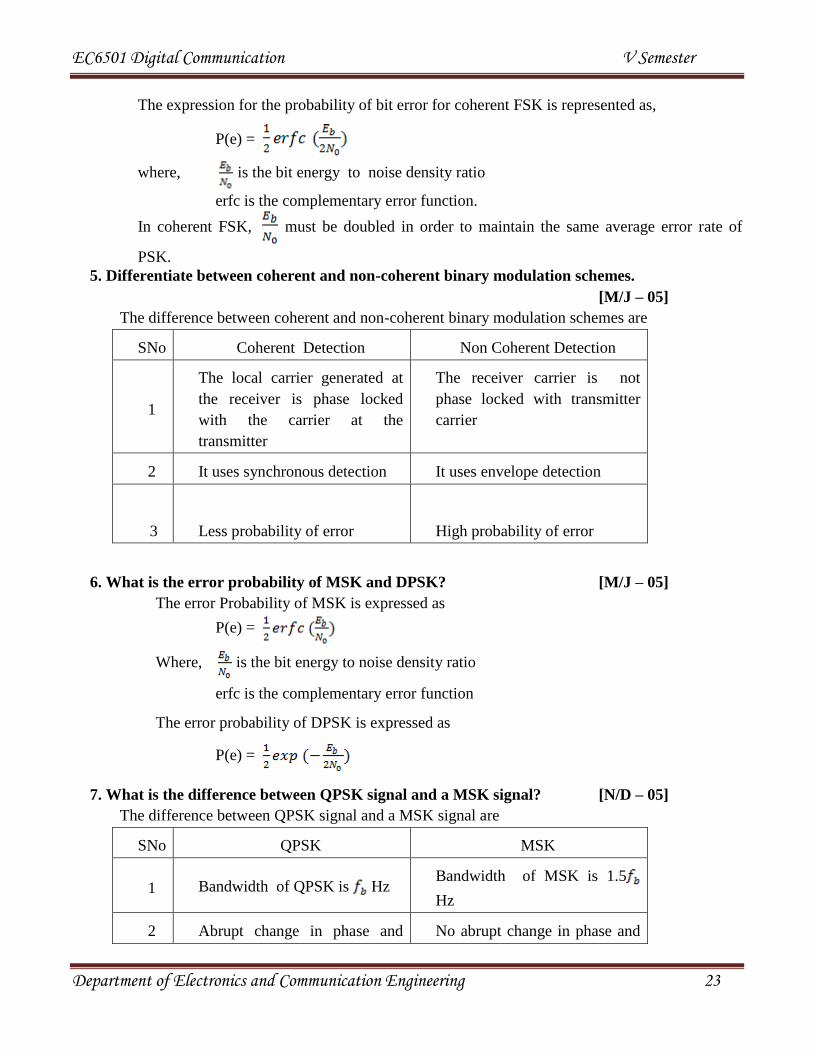
The expression for the probability of bit error for coherent FSK is represented as,
P(e) =
where, is the bit energy to noise density ratio
erfc is the complementary error function.
In coherent FSK, must be doubled in order to maintain the same average error rate of
PSK.
5. Differentiate between coherent and non-coherent binary modulation schemes.
[M/J – 05]
The difference between coherent and non-coherent binary modulation schemes are
SNo Coherent Detection Non Coherent Detection
1
The local carrier generated at
the receiver is phase locked
with the carrier at the
transmitter
The receiver carrier is not
phase locked with transmitter
carrier
2 It uses synchronous detection It uses envelope detection
3
Less probability of error
High probability of error
6. What is the error probability of MSK and DPSK? [M/J – 05]
The error Probability of MSK is expressed as
P(e) =
Where, is the bit energy to noise density ratio
erfc is the complementary error function
The error probability of DPSK is expressed as
P(e) =
7. What is the difference between QPSK signal and a MSK signal? [N/D – 05]
The difference between QPSK signal and a MSK signal are
SNo QPSK MSK
1 Bandwidth of QPSK is Hz Bandwidth of MSK is 1.5
Hz
2 Abrupt change in phase and No abrupt change in phase and

EC6501 Digital Communication V Semester
Department of Electronics and Communication Engineering 24
amplitude amplitude
3
Side lobes are bigger. So, noise
interference is high.
Smaller side lobes, smoothed
curve is obtained. MSK is
called shaped QPSK.
4 θ1(t) and θ2(t) are a pair of
quadrature carriers.
θ1(t) and θ2(t) are a pair of
modulated quadrature carriers.
8. Compare the probability of error of PSK with FSK. [M/J – 06]
The expression for the probability of bit error for coherent PSK is represented as,
P(e) =
The expression for the probability of bit error for coherent FSK is represented as,
P(e) =
where, is the bit energy - to - noise density ratio
erfc is the complementary error function.
Comparing the probability of error of PSK and FSK , in FSK must be doubled in order to
maintain the same average error rate as that of PSK.
9. What is meant by continuous phase frequency shift keying? [M/J – 07]
In FSK when the phase change is gradual at the bit transition intervals, the signal appears to be
continuous in phase. This is called continuous phase FSK or CPFSK. To have phase continuity, the
two FSK frequencies fH and fL must differ by a bit rate of fb Hz or 1/Tb sec.
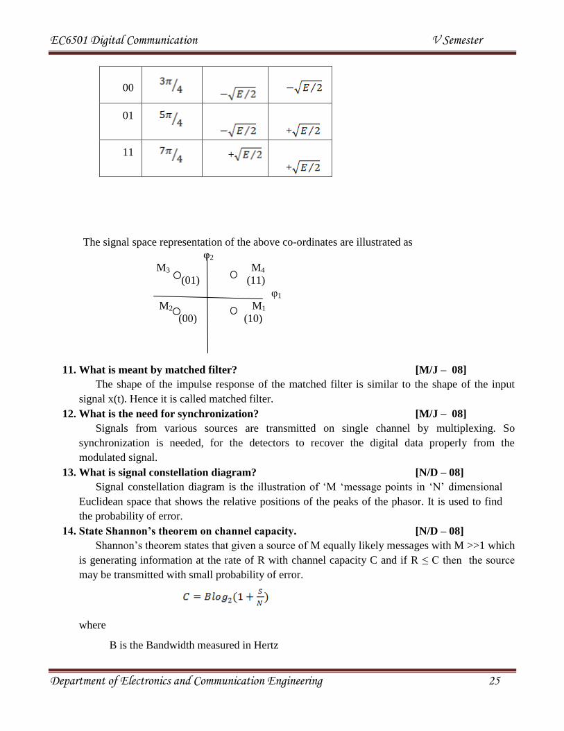
10. Draw the signal space representation of QPSK [N/D – 07]
QPSK signal is characterized by a two-dimensional signal constellation (N=2) and four
message points (M = 4).The phase and the co-ordinates of input dibit are,
SNo Phase of
QPSK
Co-ordinates of
message points
si1 si2
10 +
EC6501 Digital Communication V Semester
Department of Electronics and Communication Engineering 25
The signal space representation of the above co-ordinates are illustrated as
φ2
M3 M4
(01) (11)
φ1
M2 M1
(00) (10)
11. What is meant by matched filter? [M/J – 08]
The shape of the impulse response of the matched filter is similar to the shape of the input
signal x(t). Hence it is called matched filter.
12. What is the need for synchronization? [M/J – 08]
Signals from various sources are transmitted on single channel by multiplexing. So
synchronization is needed, for the detectors to recover the digital data properly from the
modulated signal.
13. What is signal constellation diagram? [N/D – 08]
Signal constellation diagram is the illustration of ‘M ‘message points in ‘N’ dimensional
Euclidean space that shows the relative positions of the peaks of the phasor. It is used to find
the probability of error.
14. State Shannon’s theorem on channel capacity. [N/D – 08]
Shannon’s theorem states that given a source of M equally likely messages with M >>1 which
is generating information at the rate of R with channel capacity C and if R ≤ C then the source
may be transmitted with small probability of error.
where
B is the Bandwidth measured in Hertz
00
01
+
11
+
+

EC6501 Digital Communication V Semester
Department of Electronics and Communication Engineering 26
(S/N) is Signal to Noise ratio measured in decibels.