ec 45 flat 42.9 mm, brushless, 30 wattedge.rit.edu/edge/p13021/public/ddr/maxon generator...
TRANSCRIPT
193193
max
on
EC
mo
tor
193
max
on
flat
mo
tor
12 12 24 24 36 364380 4370 4380 4380 4760 4760146 146 73 73 55.4 55.3
2940 2850 2940 2910 3290 327055.5 53.2 55.3 54.7 66.6 66.12.03 1.96 1.01 1 0.849 0.844241 206 239 230 337 33010 8.58 4.97 4.77 5.38 5.2278 76 78 77 81 81
1.2 1.4 4.83 5.03 6.69 6.890.56 0.56 2.24 2.24 4.29 4.2925.5 25.5 51 51 70.6 70.6374 374 187 187 135 13517.6 20.5 17.7 18.5 12.8 13.217.1 19.9 17.2 17.9 12.4 12.892.5 92.5 92.5 92.5 92.5 92.5
M 1:2
200142 339281 339282200189 339283 339284
May 2012 edition / subject to change maxon EC motor
Stock programStandard programSpecial program (on request)
Article Numbers
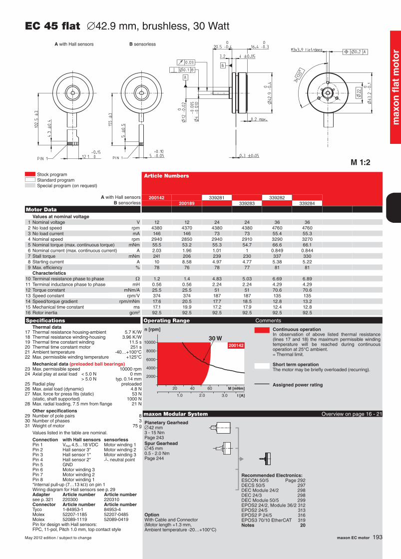
Specifications Operating Range Comments
n [rpm] Continuous operationIn observation of above listed thermal resistance (lines 17 and 18) the maximum permissible winding temperature will be reached during continuous operation at 25°C ambient.= Thermal limit.
Short term operationThe motor may be briefly overloaded (recurring).
Assigned power rating
maxon Modular System Overview on page 16 - 21
EC 45 flat ∅42.9 mm, brushless, 30 Watt
Motor DataValues at nominal voltage
1 Nominal voltage V2 No load speed rpm3 No load current mA4 Nominal speed rpm5 Nominal torque (max. continuous torque) mNm6 Nominal current (max. continuous current) A7 Stall torque mNm8 Starting current A9 Max. efficiency %
Characteristics10 Terminal resistance phase to phase W11 Terminal inductance phase to phase mH12 Torque constant mNm/A13 Speed constant rpm/V14 Speed/torque gradient rpm/mNm15 Mechanical time constant ms16 Rotor inertia gcm2
Thermal data17 Thermal resistance housing-ambient 5.7 K/W18 Thermal resistance winding-housing 3.96 K/W19 Thermal time constant winding 11.5 s20 Thermal time constant motor 251 s21 Ambient temperature -40…+100°C22 Max. permissible winding temperature +125°C
Mechanical data (preloaded ball bearings)23 Max. permissible speed 10000 rpm24 Axial play at axial load < 5.0 N 0 mm
> 5.0 N typ. 0.14 mm25 Radial play preloaded26 Max. axial load (dynamic) 4.8 N27 Max. force for press fits (static) 53 N
(static, shaft supported) 1000 N28 Max. radial loading, 7.5 mm from flange 21 N
Other specifications29 Number of pole pairs 830 Number of phases 331 Weight of motor 75 g
Values listed in the table are nominal.
Connection with Hall sensors sensorless Pin 1 VHall 4.5…18 VDC Motor winding 1 Pin 2 Hall sensor 3* Motor winding 2 Pin 3 Hall sensor 1* Motor winding 3 Pin 4 Hall sensor 2* neutral point Pin 5 GND Pin 6 Motor winding 3 Pin 7 Motor winding 2 Pin 8 Motor winding 1 *Internal pull-up (7…13 kW) on pin 1 Wiring diagram for Hall sensors see p. 29 Adapter Article number Article number see p. 321 220300 220310 Connector Article number Article number Tyco 1-84953-1 84953-4 Molex 52207-1185 52207-0485 Molex 52089-1119 52089-0419 Pin for design with Hall sensors: FPC, 11-pol, Pitch 1.0 mm, top contact style
Recommended Electronics:ESCON 50/5 Page 292DECS 50/5 297DEC Module 24/2 298 DEC 24/3 298DEC Module 50/5 299EPOS2 24/2, Module 36/2 312EPOS2 24/5 313EPOS2 P 24/5 316EPOS3 70/10 EtherCAT 319Notes 20
A with Hall sensorsB sensorless
Planetary Gearhead∅42 mm3 - 15 NmPage 243Spur Gearhead∅45 mm0.5 - 2.0 NmPage 244
A with Hall sensors B sensorless
OptionWith Cable and Connector (Motor length +1.3 mm, Ambient temperature -20…+100°C)
1206_EC_motor.indd 193 30.08.2012 08:46:42