ec-316 - 8085 projects
TRANSCRIPT

EC-316EXPENSE TRACKER
T SHREYAS BALAJII (176/EC/13)YASHNA PALIYA (195/EC/13)

CONTENTS:
Sl. No. Topic Page No.
1. Acknowledgements 3
2. Synopsis 4
3. Motivation 5
4. Circuit Description 6
5. Block Diagram 7
6. Schematic 8
7. Board layout 9
8. Fabricated Board 10
9. Gist of Code 11
10. Flowchart 12
11. Testing 13
12. Timeline 14
13. Tools/Software 15
14. Conclusion 16
15. Bibliography 17

ACKNOWLEDGEMENTS:
We, Shreyas Balajii (176/EC/13) and Yashna Paliya (195/EC/13) would like to thank Prof. D.V. Gadre for giving us this opportunity to work on a project as engaging and noteworthy as this. We learnt about the 8085 microprocessor in minute detail during the course of this project.
We would also like to thank our peers and all members of CEDT for helping us out on every step of this journey.

SYNOPSIS:
'Expenses Tracker' project is to help you keep track of your monthly or weekly expenses. Five switches let you select a category from say 'Booze', 'Groceries', 'Milk', 'fuel', 'Kapda and dhulai wala' etc.
5 more switches allow you to enter the expenses for the selected category.
Every day you hit the right combination of switches and the system would add the amount to the selected category.
At any point of time, it should tell you how much total moneyhas been spent upon the press of a button and how much ineach category. Another switch allows you to reset these expenses and start fresh.
Money spent across a number of categories such as clothes, food, drinks, etc. during the week will be noted and displayed when required. This will be implemented with the help of switches (used to input the expense in each category) and an LCD Screen to display the output.

MOTIVATION:
Often, we find ourselves at the end of the week wondering how we managed to spend an unreasonably large amount of money during the week.
This project will help us track where we spend money and hopefully teach us a little financial discipline.

CIRCUIT DESCRIPTION:
The circuit involves usage of the 8-bit 8085 microprocessor, the 8255 for interfacing I/O devices, as well as other assorted IC's as discussed below.
In the 8255, Port A and Port Cu act as an input ports, where 11 switches are interfaced in active low configuration to provide input. Port B and Port Cl act as outport ports, which are used to interface with the LCD with the appropriate command word.
In turn, the data inputs of the 8255 are connected with the I/O ports of the ROM and RAM.
In the 8085, the SID and SOD ports are used to verify the proper functioning of the IC. All the interrupt ports are grounded.
Between each IC, suitable capacitors are introduced in order to reduce fluctuations in current, which in turn prevents damage to the IC's.

BLOCK DIAGRAM:
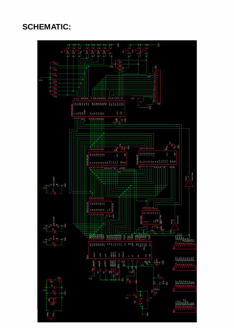
SCHEMATIC:

BOARD LAYOUT:

FABRICATED BOARD:

GIST OF CODE:
The code consists of 2 parts mainly: Write and Read.
The first part writes into preset addresses user entered values.
The user then makes use of the increment and decrement switches to enter values in multiples of 100 (64H). The valuebeing entered is also displayed using LCD, for which a different code is written.
The second part involves reading already entered values forall categories and total. It allows the user to choose a category (using switches) and display current stored value using LCD again.
The code involves usage of switches for choice and LCD fordisplay.
Also initialisation codes for 8255 and LCD are written.

FLOW CHART:

TESTING:
After soldering required components, we first tested our board using the basic SID/SOD code.
For our schematic, as SID switch was pressed, SOD was low.Hence, SOD LED went off as we pressed the SID switch.
We then checked our LCD using basic code to display WELCOME.When unable to display content, we rechecked connections from ROM to 8255 and 8255 to LCD. It turned out that the 8085 was defective and overheating. Using a different 8085 resolved the problem.
Also, we used the reset button to verify the operation of the program from the beginning, in case we got stuck in the middle of it.
We then ran our code in the ROM, and checked switches. Correspondingly we debugged our code and reran it.
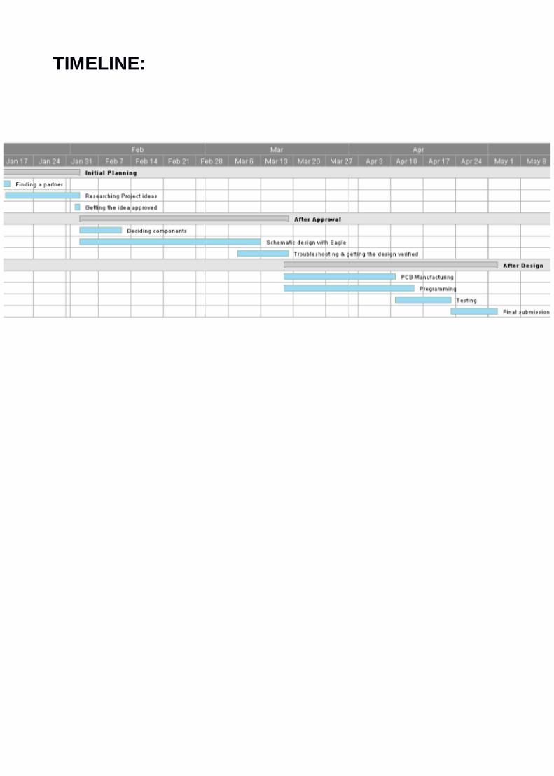
TIMELINE:

TOOLS / SOFTWARE:
1. Eagle
2. EEPROM Programmer
3. OSHON Simulator
4. Soldering station
5. Multimeter
6. Various board components.

CONCLUSION:
We successfully completed our Expense Tracker project with occasional troubleshooting assistance from our peers.
We applied theoretical concepts learnt during the semester to our project while designing, fabricating and troubleshooting it.
We have undoubtedly been enriched in practical knowledge during the course of this project.

BIBLIOGRAPHY:
1. Microprocessor Architecture, Programming, and Applications with the 8085 by Dr. Ramesh Gaonkar
2. Datasheets of various component ICs
3. Google