ebook eletronica
DESCRIPTION
asasTRANSCRIPT
Understanding Electronic Components
IndexDevelopment systemsContact us
Previous page Table of contents Next Page
Understanding Electronics Componentson-line, FREE! author: Filipovic D. Miomir
This book is meant for those people who want to create electronic devices withtheir own hands. All components are illustrated and the circuit-symbol is explainedin detail. Both simple and complex examples are provided for the beginners. Theseinclude resistors, capacitors, transformers, transistors, integrated circuits, etc andeach has its own symbol to represent it in an electrical or electronic diagram -called a circuit diagram. In order to understand how a certain device functions, it isnecessary to know each symbol and the characteristics of the component. Theseare the things we will be covering in this book.
E-mail a friend about this item
Contents:
1. RESISTORS1.1. Marking the resistors1.2. Resistor power1.3. Nonlinear resistors1.4. Practical examples1.5. Potentiometers1.6. Practical examples 2. CAPACITORS2.1. Block-capacitors 2.1.1. Marking the clock-capacitors2.2. Electrolytic capacitors2.3. Variable capacitors2.4. Practical examples 3. COILS AND TRANSFORMERS
6. THYRISTORS, TRIAC, DIAC6.1. Practical examples
7. INTEGRATED CIRCUITS7.1. Analog integrated circuits7.2. Digital integrated circuits7.3. Practical examples
8. MICROPHONES, SPEAKERS, HEADPHONES 8.1. Microphones 8.2. Speakers 8.3. Headphones 8.4. Practical examples
9. OPTO-ELECTRONIC COMPONENTS 9.1. Practical examples
mikroElektronika : books : Understanding electronic components
http://www.mikroelektronika.co.yu/english/product/books/keu/00.htm (1 of 3) [2/5/2004 19:26:34]
3.1. Coils3.2. Transformers 3.2.1. Working principles and characteristics oftransformers3.3. Practical examples
4. TRANSISTORS4.1. Working principles of transistors4.2. Basic characteristics of transistors4.3. The safest way to test transistors 4.4. TUN and TUP4.5. Practical examples 5. DIODES5.1. Marking the diodes5.2. Characteristics of diodes5.3. Practical examples
10. OTHER COMPONENTS10.1. Relays10.2. Practical examples
11. COMPONENTS CHECK 11.1. Diodes and transistors11.2. Transformers and coils 11.3. Capacitors 11.4. Potentiometers 11.5. Speakers, headphones, microphones
12. CONDUCTIVITY PROBE12.1. Semiconductors check 12.2. Other components check
To readers knowledge:
The contents published in the book "Understanding electronic components" is subject to copyright and it must not be reproduced inany form without an explicit written permission released from the editorial of mikroElektronika.
The contact address for the authorization regarding contents of this book: [email protected] .
The book was prepared with due care and attention, however the publisher doesn't accept any responsibility neither for the exactnessof the information published therein, nor for any consequences of its application.
Send us a comment on the book "Undestanding electronic components" Subject: Comment:
Name:
E-mail:
State:
mikroElektronika : books : Understanding electronic components
http://www.mikroelektronika.co.yu/english/product/books/keu/00.htm (2 of 3) [2/5/2004 19:26:34]
© C o p y r i g h t 2 0 0 3. m i k r o E l e k t r o n i k a. All Rights Reserved. For any comments contact webmaster.
mikroElektronika : books : Understanding electronic components
http://www.mikroelektronika.co.yu/english/product/books/keu/00.htm (3 of 3) [2/5/2004 19:26:34]
Understanding Electronic Components
IndexDevelopment systemsContact us
Previous page Table of contents Next page
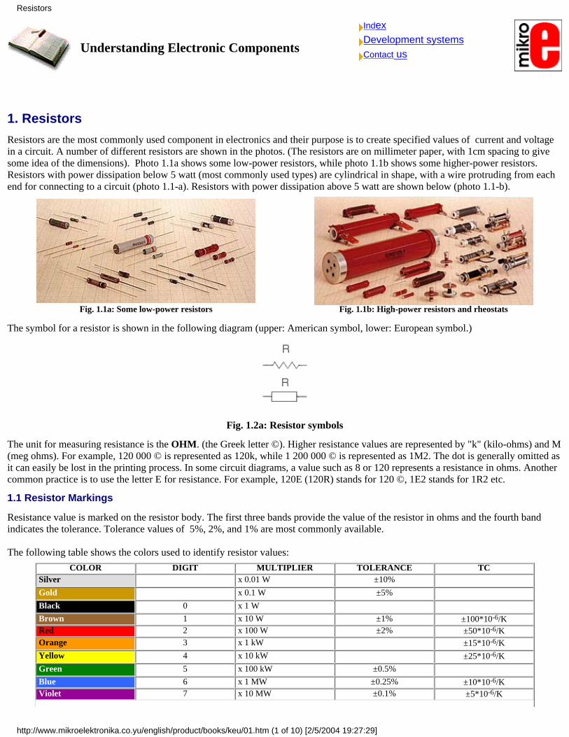
1. ResistorsResistors are the most commonly used component in electronics and their purpose is to create specified values of current and voltagein a circuit. A number of different resistors are shown in the photos. (The resistors are on millimeter paper, with 1cm spacing to givesome idea of the dimensions). Photo 1.1a shows some low-power resistors, while photo 1.1b shows some higher-power resistors.Resistors with power dissipation below 5 watt (most commonly used types) are cylindrical in shape, with a wire protruding from eachend for connecting to a circuit (photo 1.1-a). Resistors with power dissipation above 5 watt are shown below (photo 1.1-b).
Fig. 1.1a: Some low-power resistors Fig. 1.1b: High-power resistors and rheostats
The symbol for a resistor is shown in the following diagram (upper: American symbol, lower: European symbol.)
Fig. 1.2a: Resistor symbols
The unit for measuring resistance is the OHM. (the Greek letter ©). Higher resistance values are represented by "k" (kilo-ohms) and M(meg ohms). For example, 120 000 © is represented as 120k, while 1 200 000 © is represented as 1M2. The dot is generally omitted asit can easily be lost in the printing process. In some circuit diagrams, a value such as 8 or 120 represents a resistance in ohms. Anothercommon practice is to use the letter E for resistance. For example, 120E (120R) stands for 120 ©, 1E2 stands for 1R2 etc.
1.1 Resistor Markings
Resistance value is marked on the resistor body. The first three bands provide the value of the resistor in ohms and the fourth bandindicates the tolerance. Tolerance values of 5%, 2%, and 1% are most commonly available.
The following table shows the colors used to identify resistor values:
COLOR DIGIT MULTIPLIER TOLERANCE TC Silver x 0.01 W ±10% Gold x 0.1 W ±5% Black 0 x 1 W Brown 1 x 10 W ±1% ±100*10-6/K Red 2 x 100 W ±2% ±50*10-6/K Orange 3 x 1 kW ±15*10-6/K
Yellow 4 x 10 kW ±25*10-6/K
Green 5 x 100 kW ±0.5% Blue 6 x 1 MW ±0.25% ±10*10-6/K Violet 7 x 10 MW ±0.1% ±5*10-6/K
Resistors
http://www.mikroelektronika.co.yu/english/product/books/keu/01.htm (1 of 10) [2/5/2004 19:27:29]
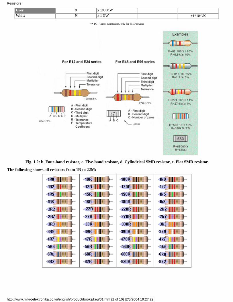
Grey 8 x 100 MW White 9 x 1 GW ±1*10-6/K
** TC - Temp. Coefficient, only for SMD devices
Fig. 1.2: b. Four-band resistor, c. Five-band resistor, d. Cylindrical SMD resistor, e. Flat SMD resistor
The following shows all resistors from 1R to 22M:
Resistors
http://www.mikroelektronika.co.yu/english/product/books/keu/01.htm (2 of 10) [2/5/2004 19:27:29]
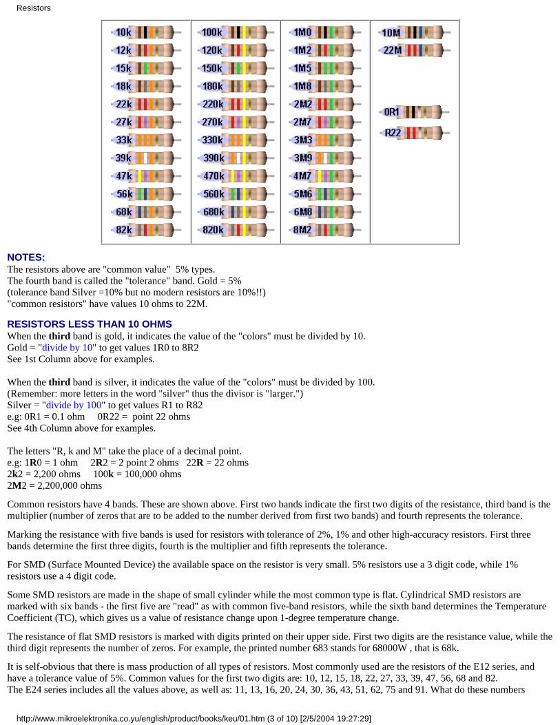
NOTES:The resistors above are "common value" 5% types.The fourth band is called the "tolerance" band. Gold = 5%(tolerance band Silver =10% but no modern resistors are 10%!!)"common resistors" have values 10 ohms to 22M.
RESISTORS LESS THAN 10 OHMSWhen the third band is gold, it indicates the value of the "colors" must be divided by 10.Gold = "divide by 10" to get values 1R0 to 8R2See 1st Column above for examples.
When the third band is silver, it indicates the value of the "colors" must be divided by 100.(Remember: more letters in the word "silver" thus the divisor is "larger.")Silver = "divide by 100" to get values R1 to R82e.g: 0R1 = 0.1 ohm 0R22 = point 22 ohms See 4th Column above for examples.
The letters "R, k and M" take the place of a decimal point.e.g: 1R0 = 1 ohm 2R2 = 2 point 2 ohms 22R = 22 ohms 2k2 = 2,200 ohms 100k = 100,000 ohms2M2 = 2,200,000 ohms
Common resistors have 4 bands. These are shown above. First two bands indicate the first two digits of the resistance, third band is themultiplier (number of zeros that are to be added to the number derived from first two bands) and fourth represents the tolerance.
Marking the resistance with five bands is used for resistors with tolerance of 2%, 1% and other high-accuracy resistors. First threebands determine the first three digits, fourth is the multiplier and fifth represents the tolerance.
For SMD (Surface Mounted Device) the available space on the resistor is very small. 5% resistors use a 3 digit code, while 1%resistors use a 4 digit code.
Some SMD resistors are made in the shape of small cylinder while the most common type is flat. Cylindrical SMD resistors aremarked with six bands - the first five are "read" as with common five-band resistors, while the sixth band determines the TemperatureCoefficient (TC), which gives us a value of resistance change upon 1-degree temperature change.
The resistance of flat SMD resistors is marked with digits printed on their upper side. First two digits are the resistance value, while thethird digit represents the number of zeros. For example, the printed number 683 stands for 68000W , that is 68k.
It is self-obvious that there is mass production of all types of resistors. Most commonly used are the resistors of the E12 series, andhave a tolerance value of 5%. Common values for the first two digits are: 10, 12, 15, 18, 22, 27, 33, 39, 47, 56, 68 and 82.The E24 series includes all the values above, as well as: 11, 13, 16, 20, 24, 30, 36, 43, 51, 62, 75 and 91. What do these numbers
Resistors
http://www.mikroelektronika.co.yu/english/product/books/keu/01.htm (3 of 10) [2/5/2004 19:27:29]
mean? It means that resistors with values for digits "39" are: 0.39W, 3.9W, 39W, 390W, 3.9kW, 39kW, etc are manufactured. (0R39,3R9, 39R, 390R, 3k9, 39k)
For some electrical circuits, the resistor tolerance is not important and it is not specified. In that case, resistors with 5% tolerance canbe used. However, devices which require resistors to have a certain amount of accuracy, need a specified tolerance.
1.2 Resistor Dissipation
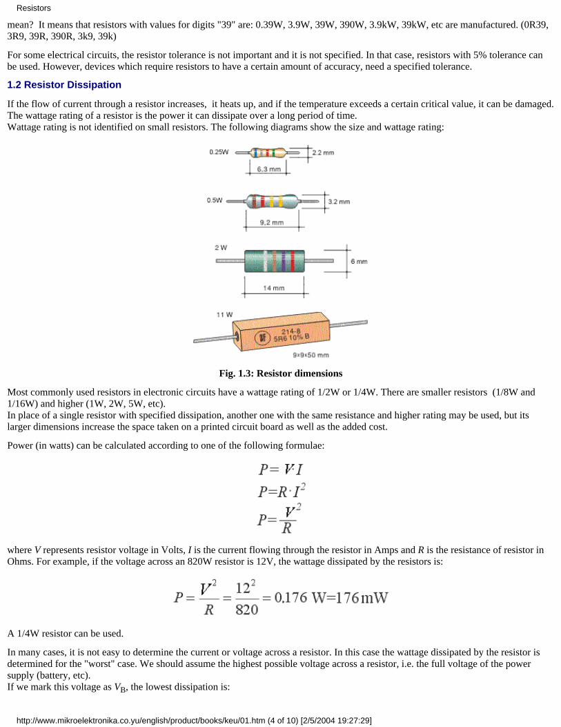
If the flow of current through a resistor increases, it heats up, and if the temperature exceeds a certain critical value, it can be damaged.The wattage rating of a resistor is the power it can dissipate over a long period of time.Wattage rating is not identified on small resistors. The following diagrams show the size and wattage rating:
Fig. 1.3: Resistor dimensions
Most commonly used resistors in electronic circuits have a wattage rating of 1/2W or 1/4W. There are smaller resistors (1/8W and1/16W) and higher (1W, 2W, 5W, etc).In place of a single resistor with specified dissipation, another one with the same resistance and higher rating may be used, but itslarger dimensions increase the space taken on a printed circuit board as well as the added cost.
Power (in watts) can be calculated according to one of the following formulae:
where V represents resistor voltage in Volts, I is the current flowing through the resistor in Amps and R is the resistance of resistor inOhms. For example, if the voltage across an 820W resistor is 12V, the wattage dissipated by the resistors is:
A 1/4W resistor can be used.
In many cases, it is not easy to determine the current or voltage across a resistor. In this case the wattage dissipated by the resistor isdetermined for the "worst" case. We should assume the highest possible voltage across a resistor, i.e. the full voltage of the powersupply (battery, etc).If we mark this voltage as VB, the lowest dissipation is:
Resistors
http://www.mikroelektronika.co.yu/english/product/books/keu/01.htm (4 of 10) [2/5/2004 19:27:29]
For example, if VB=9V, the dissipation of a 220W resistor is:
A 0.5W or higher wattage resistor should be used
1.3 Nonlinear resistors
Resistance values detailed above are a constant and do not change if the voltage or current-flow alters. But there are circuits thatrequire resistors to change value with a change in temperate or light. This function may not be linear, hence the name NONLINEARRESISTORS.
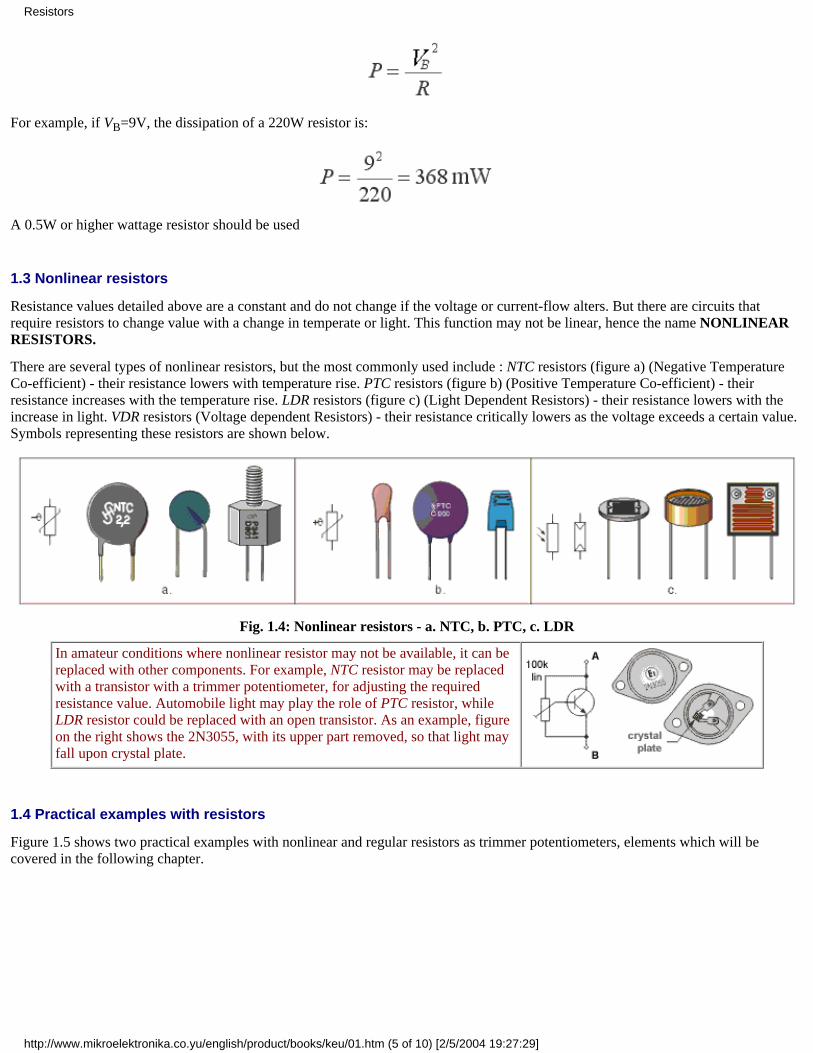
There are several types of nonlinear resistors, but the most commonly used include : NTC resistors (figure a) (Negative TemperatureCo-efficient) - their resistance lowers with temperature rise. PTC resistors (figure b) (Positive Temperature Co-efficient) - theirresistance increases with the temperature rise. LDR resistors (figure c) (Light Dependent Resistors) - their resistance lowers with theincrease in light. VDR resistors (Voltage dependent Resistors) - their resistance critically lowers as the voltage exceeds a certain value.Symbols representing these resistors are shown below.
Fig. 1.4: Nonlinear resistors - a. NTC, b. PTC, c. LDR
In amateur conditions where nonlinear resistor may not be available, it can bereplaced with other components. For example, NTC resistor may be replacedwith a transistor with a trimmer potentiometer, for adjusting the requiredresistance value. Automobile light may play the role of PTC resistor, whileLDR resistor could be replaced with an open transistor. As an example, figureon the right shows the 2N3055, with its upper part removed, so that light mayfall upon crystal plate.
1.4 Practical examples with resistors
Figure 1.5 shows two practical examples with nonlinear and regular resistors as trimmer potentiometers, elements which will becovered in the following chapter.
Resistors
http://www.mikroelektronika.co.yu/english/product/books/keu/01.htm (5 of 10) [2/5/2004 19:27:29]
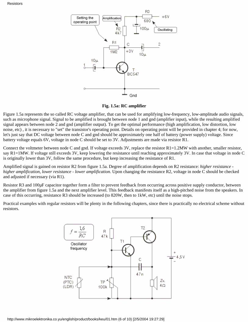
Fig. 1.5a: RC amplifier
Figure 1.5a represents the so called RC voltage amplifier, that can be used for amplifying low-frequency, low-amplitude audio signals,such as microphone signal. Signal to be amplified is brought between node 1 and gnd (amplifier input), while the resulting amplifiedsignal appears between node 2 and gnd (amplifier output). To get the optimal performance (high amplification, low distortion, lownoise, etc) , it is necessary to "set" the transistor's operating point. Details on operating point will be provided in chapter 4; for now,let's just say that DC voltage between node C and gnd should be approximately one half of battery (power supply) voltage. Sincebattery voltage equals 6V, voltage in node C should be set to 3V. Adjustments are made via resistor R1.
Connect the voltmeter between node C and gnd. If voltage exceeds 3V, replace the resistor R1=1.2MW with another, smaller resistor,say R1=1MW. If voltage still exceeds 3V, keep lowering the resistance until reaching approximately 3V. In case that voltage in node Cis originally lower than 3V, follow the same procedure, but keep increasing the resistance of R1.
Amplified signal is gained on resistor R2 from figure 1.5a. Degree of amplification depends on R2 resistance: higher resistance -higher amplification, lower resistance - lower amplification. Upon changing the resistance R2, voltage in node C should be checkedand adjusted if necessary (via R1).
Resistor R3 and 100µF capacitor together form a filter to prevent feedback from occurring across positive supply conductor, betweenthe amplifier from figure 1.5a and the next amplifier level. This feedback manifests itself as a high-pitched noise from the speakers. Incase of this occurring, resistance R3 should be increased (to 820W, then to 1kW, etc) until the noise stops.
Practical examples with regular resistors will be plenty in the following chapters, since there is practically no electrical scheme withoutresistors.
Resistors
http://www.mikroelektronika.co.yu/english/product/books/keu/01.htm (6 of 10) [2/5/2004 19:27:29]
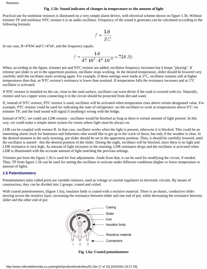
Fig. 1.5b: Sound indicator of changes in temperature or the amount of light
Practical use for nonlinear resistors is illustrated on a very simple alarm device, with electrical scheme shown on figure 1.5b. Withouttrimmer TP and nonlinear NTC resistor it is an audio oscillator. Frequency of the sound it generates can be calculated according to thefollowing formula:
In our case, R=47kW and C=47nF, and the frequency equals:
When, according to the figure, trimmer pot and NTC resistor are added, oscillator frequency increases but it keeps "playing". Iftrimmer pot slider is set to the uppermost position, oscillator stops working. At the desired temperature, slider should be lowered verycarefully until the oscillator starts working again. For example, if these settings were made at 2°C, oscillator remains still at highertemperatures than that, as NTC resistor's resistance is lower than nominal. If temperature falls the resistance increases and at 2°Coscillator is activated.
If NTC resistor is installed on the car, close to the road surface, oscillator can warn driver if the road is covered with ice. Naturally,resistor and two copper wires connecting it to the circuit should be protected from dirt and water.
If, instead of NTC resistor, PTC resistor is used, oscillator will be activated when temperature rises above certain designated value. Forexample, PTC resistor could be used for indicating the state of refrigerator: set the oscillator to work at temperatures above 6°C viatrimmer TP, and the loud sound will signal if anything's wrong with the fridge.
Instead of NTC, we could use LDR resistor - oscillator would be blocked as long as there is certain amount of light present. In thisway, we could make a simple alarm system for rooms where light must be always on.
LDR can be coupled with resistor R. In that case, oscillator works when the light is present, otherwise it is blocked. This could be aninteresting alarm clock for huntsmen and fishermen who would like to get up in the crack of dawn, but only if the weather is clear. Inthe desired moment in the early morning, pot slider should be set to the uppermost position. Then, it should be carefully lowered, untilthe oscillator is started - this the desired position of the slider. During the night, oscillator will be blocked, since there is no light andLDR resistance is very high. As amount of light increases in the morning, LDR resistance drops and the oscillator is activated whenLDR is illuminated with the accurate amount of light matching the previous settings.
Trimmer pot from the figure 1.5b is used for fine adjustments. Aside from that, it can be used for modifying the circuit, if needed.Thus, TP from figure 1.5b can be used for setting the oscillator to activate under different conditions (higher or lower temperature oramount of light).
1.5 Potentiometers
Potentiometers (also called pots) are variable resistors, used as voltage or current regulators in electronic circuits. By means ofconstruction, they can be divided into 2 groups: coated and coiled.
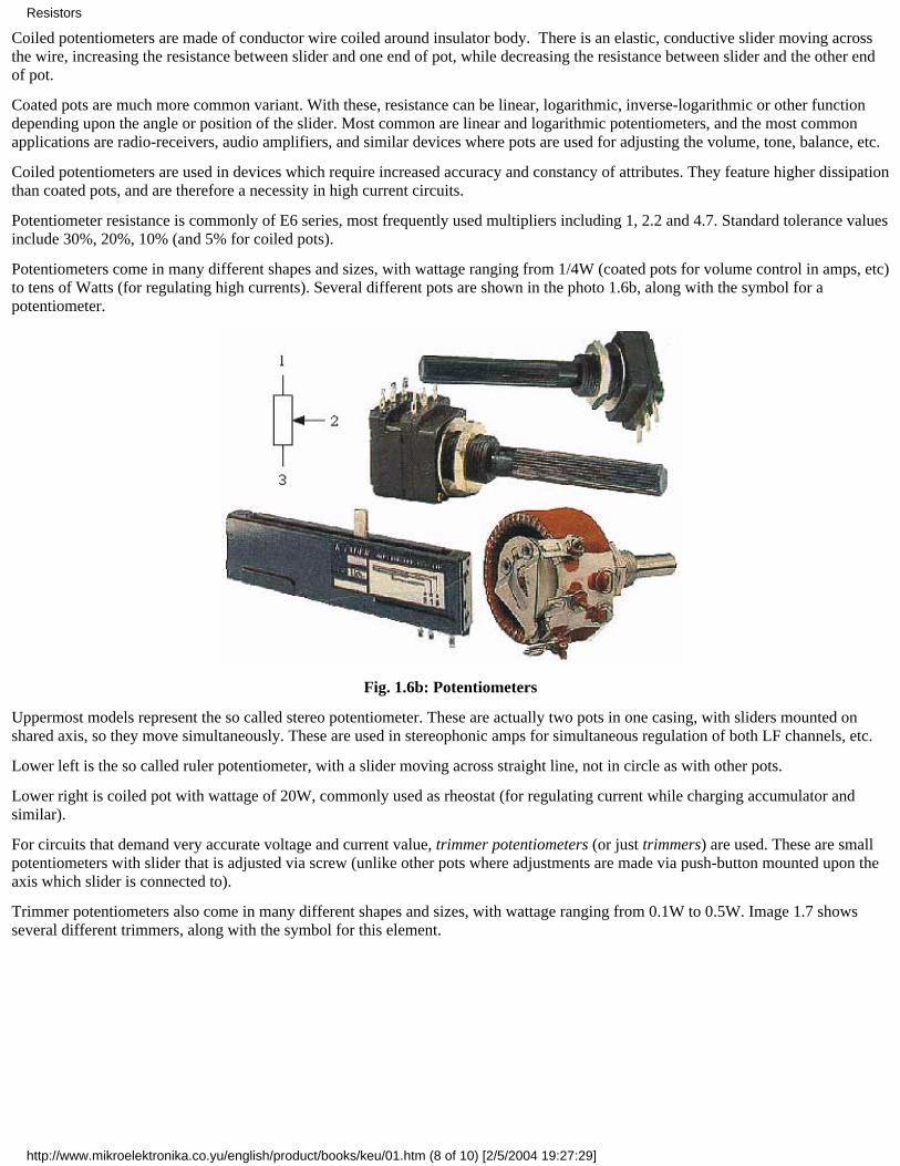
With coated potentiometers, (figure 1.6a), insulator body is coated with a resistive material. There is an elastic, conductive slidermoving across the resistive layer, increasing the resistance between slider and one end of pot, while decreasing the resistance betweenslider and the other end of pot.
Fig. 1.6a: Coated potentiometer
Resistors
http://www.mikroelektronika.co.yu/english/product/books/keu/01.htm (7 of 10) [2/5/2004 19:27:29]
Coiled potentiometers are made of conductor wire coiled around insulator body. There is an elastic, conductive slider moving acrossthe wire, increasing the resistance between slider and one end of pot, while decreasing the resistance between slider and the other endof pot.
Coated pots are much more common variant. With these, resistance can be linear, logarithmic, inverse-logarithmic or other functiondepending upon the angle or position of the slider. Most common are linear and logarithmic potentiometers, and the most commonapplications are radio-receivers, audio amplifiers, and similar devices where pots are used for adjusting the volume, tone, balance, etc.
Coiled potentiometers are used in devices which require increased accuracy and constancy of attributes. They feature higher dissipationthan coated pots, and are therefore a necessity in high current circuits.
Potentiometer resistance is commonly of E6 series, most frequently used multipliers including 1, 2.2 and 4.7. Standard tolerance valuesinclude 30%, 20%, 10% (and 5% for coiled pots).
Potentiometers come in many different shapes and sizes, with wattage ranging from 1/4W (coated pots for volume control in amps, etc)to tens of Watts (for regulating high currents). Several different pots are shown in the photo 1.6b, along with the symbol for apotentiometer.
Fig. 1.6b: Potentiometers
Uppermost models represent the so called stereo potentiometer. These are actually two pots in one casing, with sliders mounted onshared axis, so they move simultaneously. These are used in stereophonic amps for simultaneous regulation of both LF channels, etc.
Lower left is the so called ruler potentiometer, with a slider moving across straight line, not in circle as with other pots.
Lower right is coiled pot with wattage of 20W, commonly used as rheostat (for regulating current while charging accumulator andsimilar).
For circuits that demand very accurate voltage and current value, trimmer potentiometers (or just trimmers) are used. These are smallpotentiometers with slider that is adjusted via screw (unlike other pots where adjustments are made via push-button mounted upon theaxis which slider is connected to).
Trimmer potentiometers also come in many different shapes and sizes, with wattage ranging from 0.1W to 0.5W. Image 1.7 showsseveral different trimmers, along with the symbol for this element.
Resistors
http://www.mikroelektronika.co.yu/english/product/books/keu/01.htm (8 of 10) [2/5/2004 19:27:29]
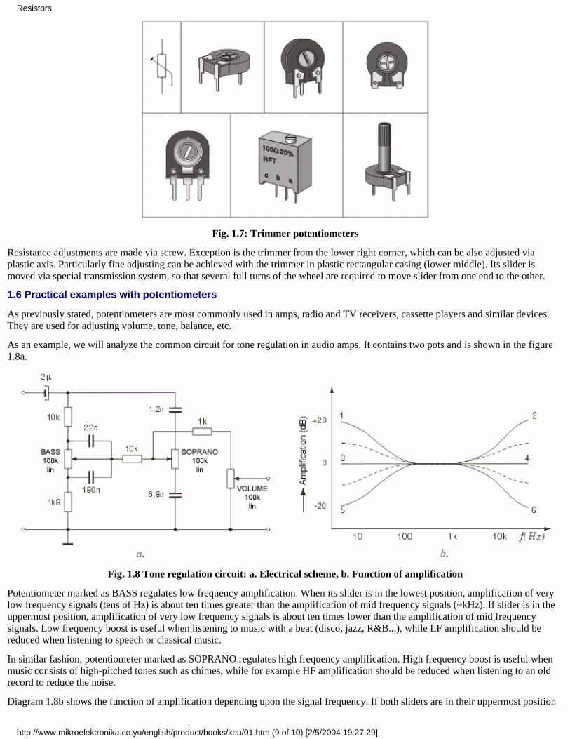
Fig. 1.7: Trimmer potentiometers
Resistance adjustments are made via screw. Exception is the trimmer from the lower right corner, which can be also adjusted viaplastic axis. Particularly fine adjusting can be achieved with the trimmer in plastic rectangular casing (lower middle). Its slider ismoved via special transmission system, so that several full turns of the wheel are required to move slider from one end to the other.
1.6 Practical examples with potentiometers
As previously stated, potentiometers are most commonly used in amps, radio and TV receivers, cassette players and similar devices.They are used for adjusting volume, tone, balance, etc.
As an example, we will analyze the common circuit for tone regulation in audio amps. It contains two pots and is shown in the figure1.8a.
Fig. 1.8 Tone regulation circuit: a. Electrical scheme, b. Function of amplification
Potentiometer marked as BASS regulates low frequency amplification. When its slider is in the lowest position, amplification of verylow frequency signals (tens of Hz) is about ten times greater than the amplification of mid frequency signals (~kHz). If slider is in theuppermost position, amplification of very low frequency signals is about ten times lower than the amplification of mid frequencysignals. Low frequency boost is useful when listening to music with a beat (disco, jazz, R&B...), while LF amplification should bereduced when listening to speech or classical music.
In similar fashion, potentiometer marked as SOPRANO regulates high frequency amplification. High frequency boost is useful whenmusic consists of high-pitched tones such as chimes, while for example HF amplification should be reduced when listening to an oldrecord to reduce the noise.
Diagram 1.8b shows the function of amplification depending upon the signal frequency. If both sliders are in their uppermost position
Resistors
http://www.mikroelektronika.co.yu/english/product/books/keu/01.htm (9 of 10) [2/5/2004 19:27:29]

function is described with a curve 1-2, if both are in mid position function is described with a line 3-4, and if both sliders are in theirlowest position function is described with a curve 5-6. Setting the pair of sliders to any other possible position results in a curvebetween curves 1-2 and 5-6.
Potentiometers BASS and SOPRANO are coated by construction and linear by resistance function.
Third pot from the image serves as volume regulator. It is also coated by construction, but is logarithmic by resistance function (hencethe mark log underneath it)
Example with trimmer is given in the text accompanying the image 1.5b.
Previous page Table of contents Next page
© C o p y r i g h t 2 0 0 3. m i k r o E l e k t r o n i k a. All Rights Reserved. For any comments contact webmaster.
Resistors
http://www.mikroelektronika.co.yu/english/product/books/keu/01.htm (10 of 10) [2/5/2004 19:27:29]
Understanding Electronic Components
IndexDevelopment systemsContact us
Previous page Table of contents Next page
2. CapacitorsCapacitors are common components of electronic circuits, used almost as frequently as resistors. Basic difference between the two isthe fact that capacitor resistance (called reactance) depends on voltage frequency, not only on capacitors' features. Common mark forreactance is Xc and it can be calculated using the following formula:
f representing the frequency in Hz and C representing the capacity in Farads.
For example, 5nF-capacitor's reactance at f=125kHz equals:
while, at f=1.25MHz, it equals:
Capacitor has infinitely high reactance for direct current, because f=0.
Capacitors are used in circuits for filtering signals of specified frequency. They are common components of electrical filters, oscillatorcircuits, etc.
Basic characteristic of capacitor is its capacity - higher the capacity is, higher is the amount of electricity capacitor can accumulate.Capacity is measured in Farads (F). As one Farad represents fairly high capacity value, microfarad (µF), nanofarad (nF) and picofarad(pF) are commonly used. As a reminder, relations between units are:
1F=106µF=109nF=1012pF,
that is 1µF=1000nF and 1nF=1000pF. It is essential to remember this notation, as same values may be marked differently in differentelectrical schemes. For example, 1500pF may be used interchangeably with 1.5nF, 100nF may replace 0.1µF, etc. Bear in mind thatsimpler notation system is used, as with resistors. If the mark by the capacitor in the scheme reads 120 (or 120E) capacity equals120pF, 1n2 stands for 1.2nF, n22 stands for 0.22nF, while .1µ (or .1u) stands for 0.1µF capacity and so forth.
Capacitors come in various shapes and sizes, depending on their capacity, working voltage, insulator type, temperature coefficient andother factors. All capacitors can divided in two groups: those with changeable capacity values and those with fixed capacity values.These will covered in the following chapters.
2.1 Block-capacitors
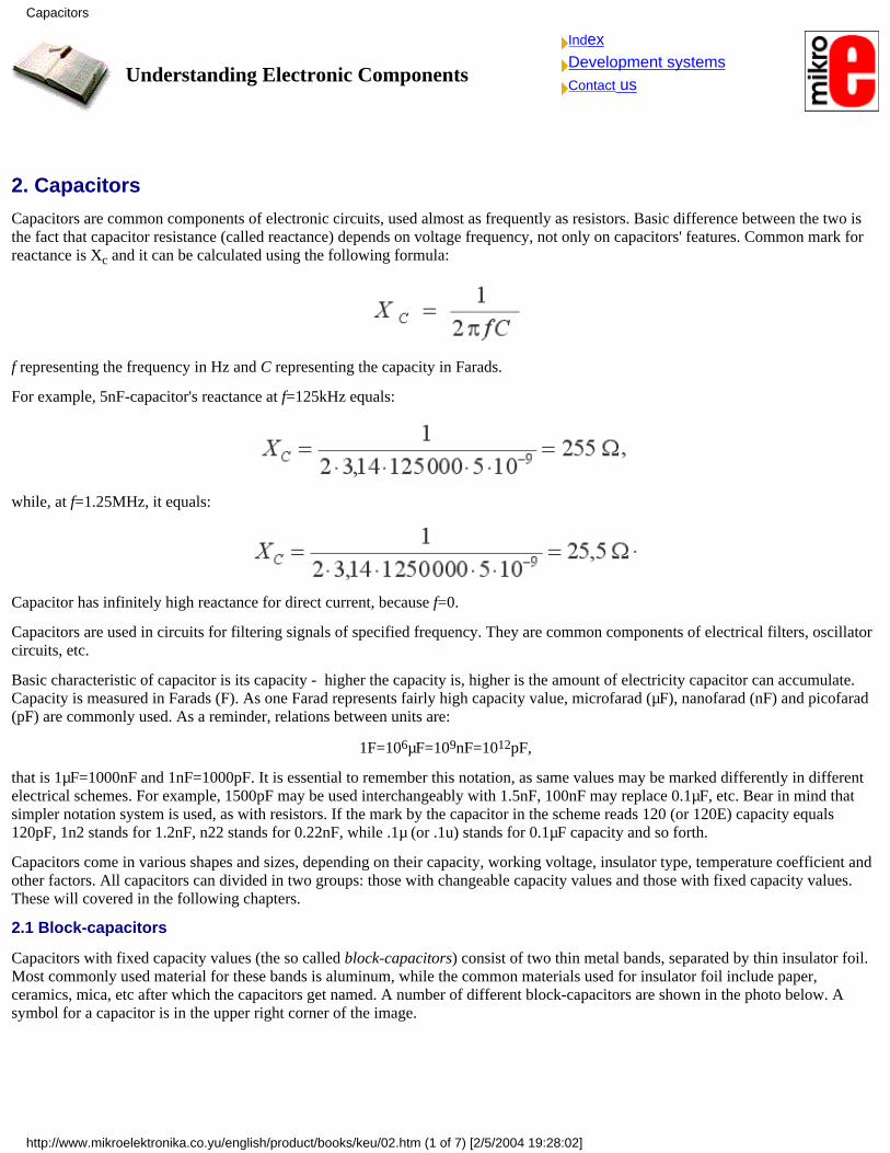
Capacitors with fixed capacity values (the so called block-capacitors) consist of two thin metal bands, separated by thin insulator foil.Most commonly used material for these bands is aluminum, while the common materials used for insulator foil include paper,ceramics, mica, etc after which the capacitors get named. A number of different block-capacitors are shown in the photo below. Asymbol for a capacitor is in the upper right corner of the image.
Capacitors
http://www.mikroelektronika.co.yu/english/product/books/keu/02.htm (1 of 7) [2/5/2004 19:28:02]
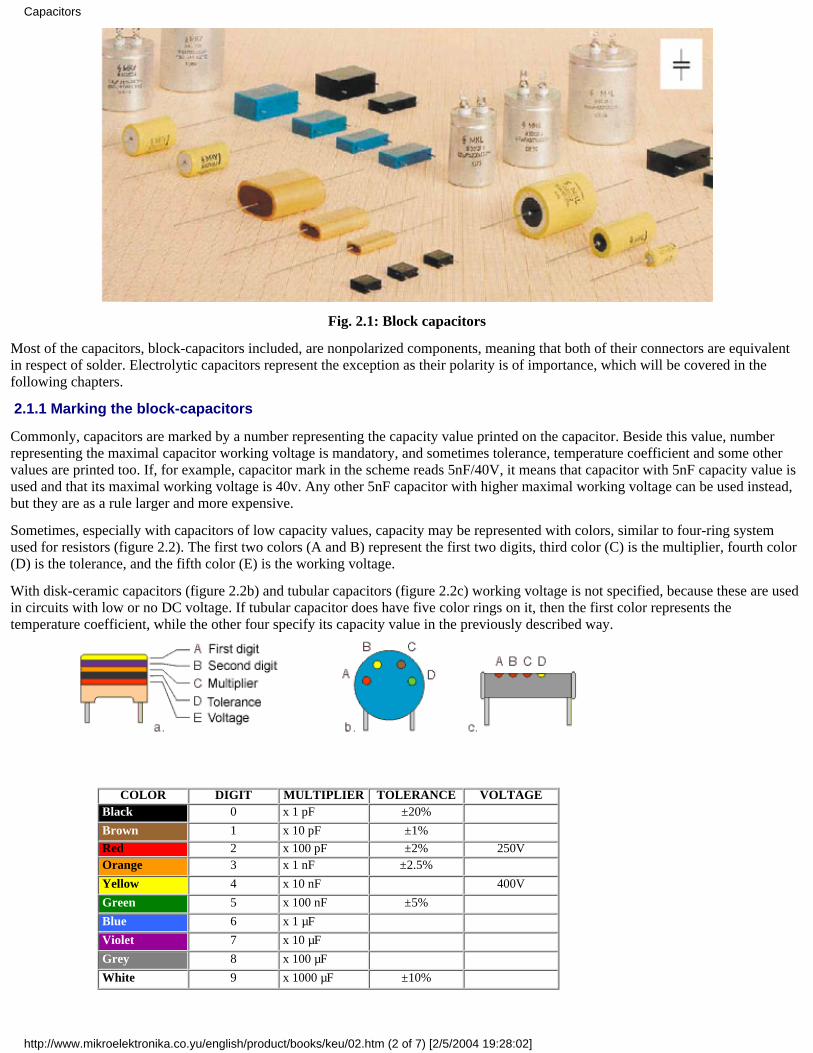
Fig. 2.1: Block capacitors
Most of the capacitors, block-capacitors included, are nonpolarized components, meaning that both of their connectors are equivalentin respect of solder. Electrolytic capacitors represent the exception as their polarity is of importance, which will be covered in thefollowing chapters.
2.1.1 Marking the block-capacitors
Commonly, capacitors are marked by a number representing the capacity value printed on the capacitor. Beside this value, numberrepresenting the maximal capacitor working voltage is mandatory, and sometimes tolerance, temperature coefficient and some othervalues are printed too. If, for example, capacitor mark in the scheme reads 5nF/40V, it means that capacitor with 5nF capacity value isused and that its maximal working voltage is 40v. Any other 5nF capacitor with higher maximal working voltage can be used instead,but they are as a rule larger and more expensive.
Sometimes, especially with capacitors of low capacity values, capacity may be represented with colors, similar to four-ring systemused for resistors (figure 2.2). The first two colors (A and B) represent the first two digits, third color (C) is the multiplier, fourth color(D) is the tolerance, and the fifth color (E) is the working voltage.
With disk-ceramic capacitors (figure 2.2b) and tubular capacitors (figure 2.2c) working voltage is not specified, because these are usedin circuits with low or no DC voltage. If tubular capacitor does have five color rings on it, then the first color represents thetemperature coefficient, while the other four specify its capacity value in the previously described way.
COLOR DIGIT MULTIPLIER TOLERANCE VOLTAGE Black 0 x 1 pF ±20% Brown 1 x 10 pF ±1% Red 2 x 100 pF ±2% 250V Orange 3 x 1 nF ±2.5% Yellow 4 x 10 nF 400V
Green 5 x 100 nF ±5% Blue 6 x 1 µF Violet 7 x 10 µF Grey 8 x 100 µF White 9 x 1000 µF ±10%
Capacitors
http://www.mikroelektronika.co.yu/english/product/books/keu/02.htm (2 of 7) [2/5/2004 19:28:02]
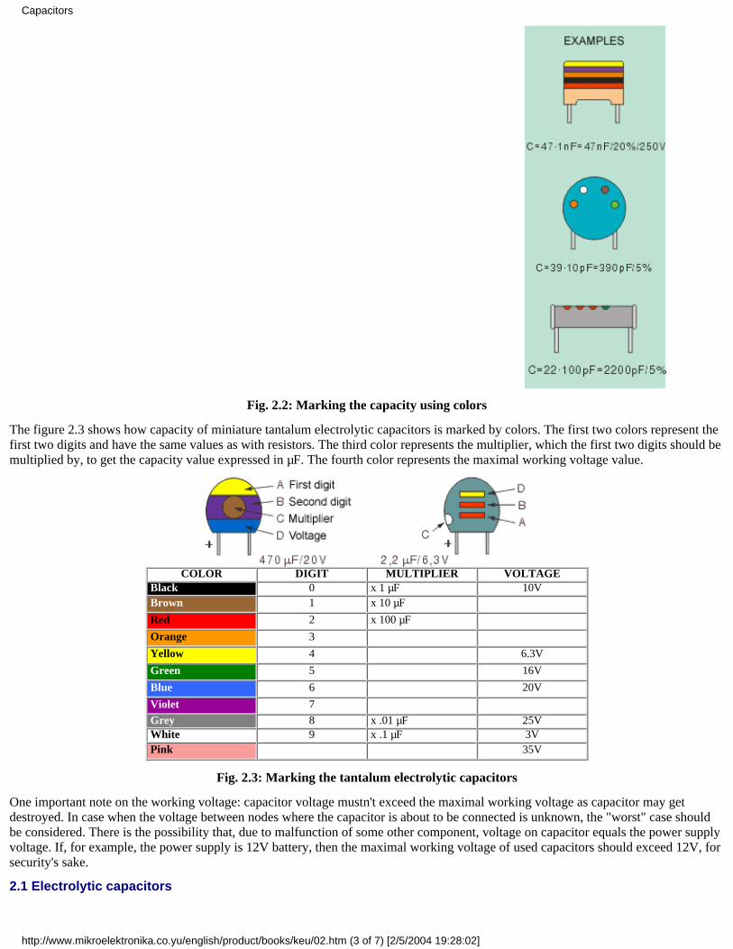
Fig. 2.2: Marking the capacity using colors
The figure 2.3 shows how capacity of miniature tantalum electrolytic capacitors is marked by colors. The first two colors represent thefirst two digits and have the same values as with resistors. The third color represents the multiplier, which the first two digits should bemultiplied by, to get the capacity value expressed in µF. The fourth color represents the maximal working voltage value.
COLOR DIGIT MULTIPLIER VOLTAGE Black 0 x 1 µF 10V Brown 1 x 10 µF Red 2 x 100 µF Orange 3 Yellow 4 6.3V
Green 5 16V
Blue 6 20V
Violet 7 Grey 8 x .01 µF 25V White 9 x .1 µF 3V Pink 35V
Fig. 2.3: Marking the tantalum electrolytic capacitors
One important note on the working voltage: capacitor voltage mustn't exceed the maximal working voltage as capacitor may getdestroyed. In case when the voltage between nodes where the capacitor is about to be connected is unknown, the "worst" case shouldbe considered. There is the possibility that, due to malfunction of some other component, voltage on capacitor equals the power supplyvoltage. If, for example, the power supply is 12V battery, then the maximal working voltage of used capacitors should exceed 12V, forsecurity's sake.
2.1 Electrolytic capacitors
Capacitors
http://www.mikroelektronika.co.yu/english/product/books/keu/02.htm (3 of 7) [2/5/2004 19:28:02]
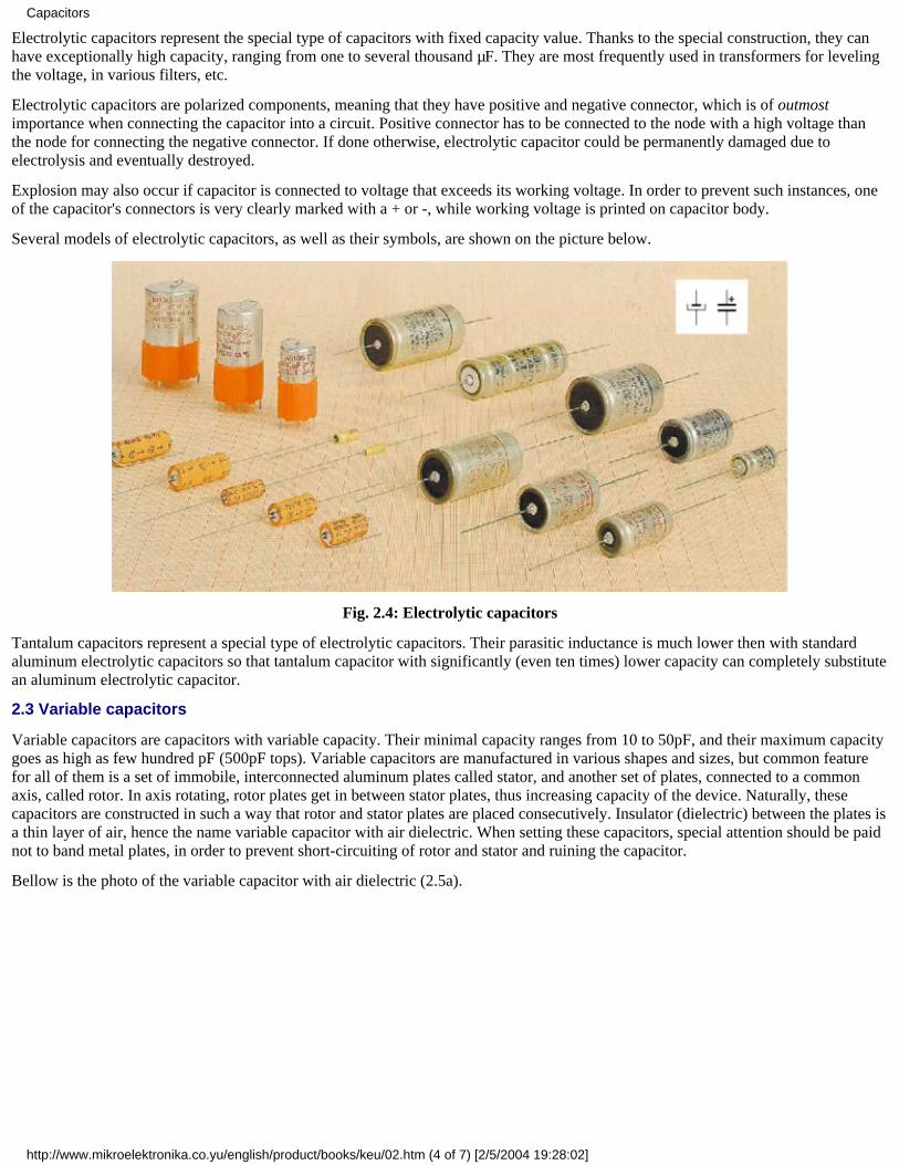
Electrolytic capacitors represent the special type of capacitors with fixed capacity value. Thanks to the special construction, they canhave exceptionally high capacity, ranging from one to several thousand µF. They are most frequently used in transformers for levelingthe voltage, in various filters, etc.
Electrolytic capacitors are polarized components, meaning that they have positive and negative connector, which is of outmostimportance when connecting the capacitor into a circuit. Positive connector has to be connected to the node with a high voltage thanthe node for connecting the negative connector. If done otherwise, electrolytic capacitor could be permanently damaged due toelectrolysis and eventually destroyed.
Explosion may also occur if capacitor is connected to voltage that exceeds its working voltage. In order to prevent such instances, oneof the capacitor's connectors is very clearly marked with a + or -, while working voltage is printed on capacitor body.
Several models of electrolytic capacitors, as well as their symbols, are shown on the picture below.
Fig. 2.4: Electrolytic capacitors
Tantalum capacitors represent a special type of electrolytic capacitors. Their parasitic inductance is much lower then with standardaluminum electrolytic capacitors so that tantalum capacitor with significantly (even ten times) lower capacity can completely substitutean aluminum electrolytic capacitor.
2.3 Variable capacitors
Variable capacitors are capacitors with variable capacity. Their minimal capacity ranges from 10 to 50pF, and their maximum capacitygoes as high as few hundred pF (500pF tops). Variable capacitors are manufactured in various shapes and sizes, but common featurefor all of them is a set of immobile, interconnected aluminum plates called stator, and another set of plates, connected to a commonaxis, called rotor. In axis rotating, rotor plates get in between stator plates, thus increasing capacity of the device. Naturally, thesecapacitors are constructed in such a way that rotor and stator plates are placed consecutively. Insulator (dielectric) between the plates isa thin layer of air, hence the name variable capacitor with air dielectric. When setting these capacitors, special attention should be paidnot to band metal plates, in order to prevent short-circuiting of rotor and stator and ruining the capacitor.
Bellow is the photo of the variable capacitor with air dielectric (2.5a).
Capacitors
http://www.mikroelektronika.co.yu/english/product/books/keu/02.htm (4 of 7) [2/5/2004 19:28:02]
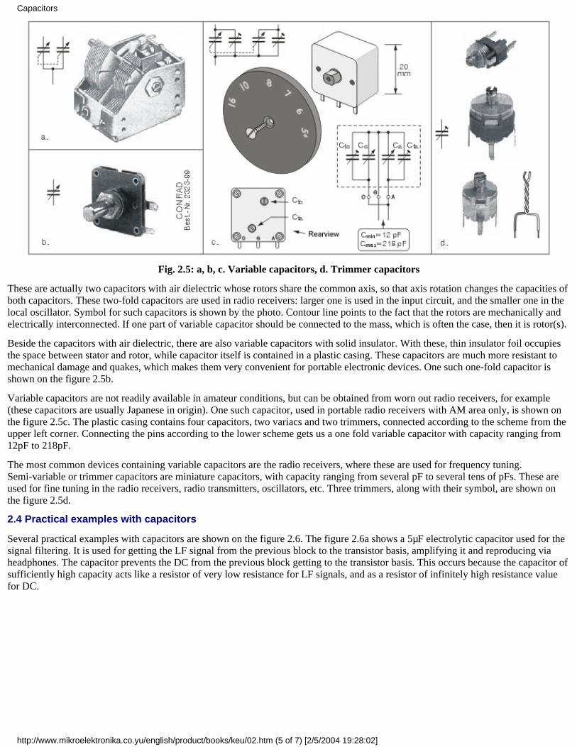
Fig. 2.5: a, b, c. Variable capacitors, d. Trimmer capacitors
These are actually two capacitors with air dielectric whose rotors share the common axis, so that axis rotation changes the capacities ofboth capacitors. These two-fold capacitors are used in radio receivers: larger one is used in the input circuit, and the smaller one in thelocal oscillator. Symbol for such capacitors is shown by the photo. Contour line points to the fact that the rotors are mechanically andelectrically interconnected. If one part of variable capacitor should be connected to the mass, which is often the case, then it is rotor(s).
Beside the capacitors with air dielectric, there are also variable capacitors with solid insulator. With these, thin insulator foil occupiesthe space between stator and rotor, while capacitor itself is contained in a plastic casing. These capacitors are much more resistant tomechanical damage and quakes, which makes them very convenient for portable electronic devices. One such one-fold capacitor isshown on the figure 2.5b.
Variable capacitors are not readily available in amateur conditions, but can be obtained from worn out radio receivers, for example(these capacitors are usually Japanese in origin). One such capacitor, used in portable radio receivers with AM area only, is shown onthe figure 2.5c. The plastic casing contains four capacitors, two variacs and two trimmers, connected according to the scheme from theupper left corner. Connecting the pins according to the lower scheme gets us a one fold variable capacitor with capacity ranging from12pF to 218pF.
The most common devices containing variable capacitors are the radio receivers, where these are used for frequency tuning.Semi-variable or trimmer capacitors are miniature capacitors, with capacity ranging from several pF to several tens of pFs. These areused for fine tuning in the radio receivers, radio transmitters, oscillators, etc. Three trimmers, along with their symbol, are shown onthe figure 2.5d.
2.4 Practical examples with capacitors
Several practical examples with capacitors are shown on the figure 2.6. The figure 2.6a shows a 5µF electrolytic capacitor used for thesignal filtering. It is used for getting the LF signal from the previous block to the transistor basis, amplifying it and reproducing viaheadphones. The capacitor prevents the DC from the previous block getting to the transistor basis. This occurs because the capacitor ofsufficiently high capacity acts like a resistor of very low resistance for LF signals, and as a resistor of infinitely high resistance valuefor DC.
Capacitors
http://www.mikroelektronika.co.yu/english/product/books/keu/02.htm (5 of 7) [2/5/2004 19:28:02]
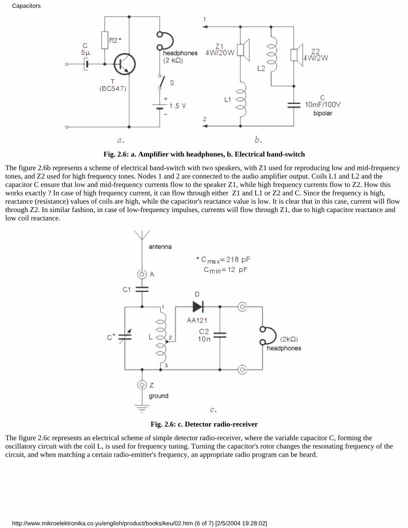
Fig. 2.6: a. Amplifier with headphones, b. Electrical band-switch
The figure 2.6b represents a scheme of electrical band-switch with two speakers, with Z1 used for reproducing low and mid-frequencytones, and Z2 used for high frequency tones. Nodes 1 and 2 are connected to the audio amplifier output. Coils L1 and L2 and thecapacitor C ensure that low and mid-frequency currents flow to the speaker Z1, while high frequency currents flow to Z2. How thisworks exactly ? In case of high frequency current, it can flow through either Z1 and L1 or Z2 and C. Since the frequency is high,reactance (resistance) values of coils are high, while the capacitor's reactance value is low. It is clear that in this case, current will flowthrough Z2. In similar fashion, in case of low-frequency impulses, currents will flow through Z1, due to high capacitor reactance andlow coil reactance.
Fig. 2.6: c. Detector radio-receiver
The figure 2.6c represents an electrical scheme of simple detector radio-receiver, where the variable capacitor C, forming theoscillatory circuit with the coil L, is used for frequency tuning. Turning the capacitor's rotor changes the resonating frequency of thecircuit, and when matching a certain radio-emitter's frequency, an appropriate radio program can be heard.
Previous page Table of contents Next page
Capacitors
http://www.mikroelektronika.co.yu/english/product/books/keu/02.htm (6 of 7) [2/5/2004 19:28:02]

© C o p y r i g h t 2 0 0 3. m i k r o E l e k t r o n i k a. All Rights Reserved. For any comments contact webmaster.
Capacitors
http://www.mikroelektronika.co.yu/english/product/books/keu/02.htm (7 of 7) [2/5/2004 19:28:02]
Understanding Electronic Components
IndexDevelopment systemsContact us
Previous page Table of contents Next page
3. Coils and transformers3.1 Coils
Coils are not that common components of electronic devices as resistors and capacitors are. They are encountered in variousoscillators, radio-receivers, radio-emitters and similar devices containing oscillatory circuits. In amateur conditions, coil can be madeby coiling one or more layers of isolated copper wire onto a cylindrical insulator body (PVC, cardboard, etc.) in a specified fashion.Factory made coils come in different shapes and sizes, but the common feature for all of them is an insulator body with coiled copperwire.
Basic characteristic of every coil is its inductance. Inductance is measured in Henry (H), but more common are milihenry (mH) andmicrohenry (µH) as one Henry is quite high inductance value. As a reminder:
1H = 1000mH = 106 µH.
Coil reactance is marked by XL, and can be calculated using the following formula:
where f represents the frequency of coil voltage in Hz and the L represents the coil inductance in H.
For example, if f equals 684 kHz, while L=0.6 mH, coil reactance will be:
The same coil would have three times higher reactive resistance at three times higher frequency and vice versa. As can be seen fromthe formula above, coil reactance is in direct proportion to voltage frequency, so that coils, as well as capacitors, are used in differentcircuits for filtering voltage of specified frequency. Note that coil reactance equals zero for DC, for f=0 in that case.
Several coils are shown on the figures 3.1, 3.2, 3.3, and 3.4.
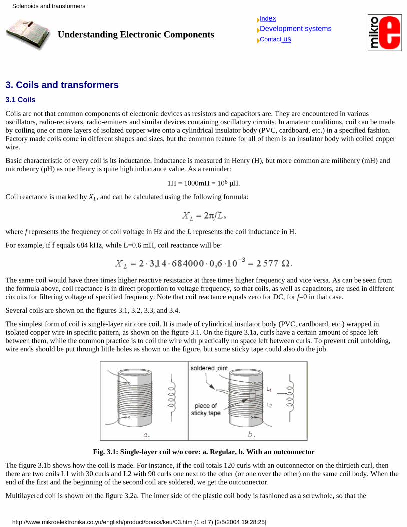
The simplest form of coil is single-layer air core coil. It is made of cylindrical insulator body (PVC, cardboard, etc.) wrapped inisolated copper wire in specific pattern, as shown on the figure 3.1. On the figure 3.1a, curls have a certain amount of space leftbetween them, while the common practice is to coil the wire with practically no space left between curls. To prevent coil unfolding,wire ends should be put through little holes as shown on the figure, but some sticky tape could also do the job.
Fig. 3.1: Single-layer coil w/o core: a. Regular, b. With an outconnector
The figure 3.1b shows how the coil is made. For instance, if the coil totals 120 curls with an outconnector on the thirtieth curl, thenthere are two coils L1 with 30 curls and L2 with 90 curls one next to the other (or one over the other) on the same coil body. When theend of the first and the beginning of the second coil are soldered, we get the outconnector.
Multilayered coil is shown on the figure 3.2a. The inner side of the plastic coil body is fashioned as a screwhole, so that the
Solenoids and transformers
http://www.mikroelektronika.co.yu/english/product/books/keu/03.htm (1 of 7) [2/5/2004 19:28:25]
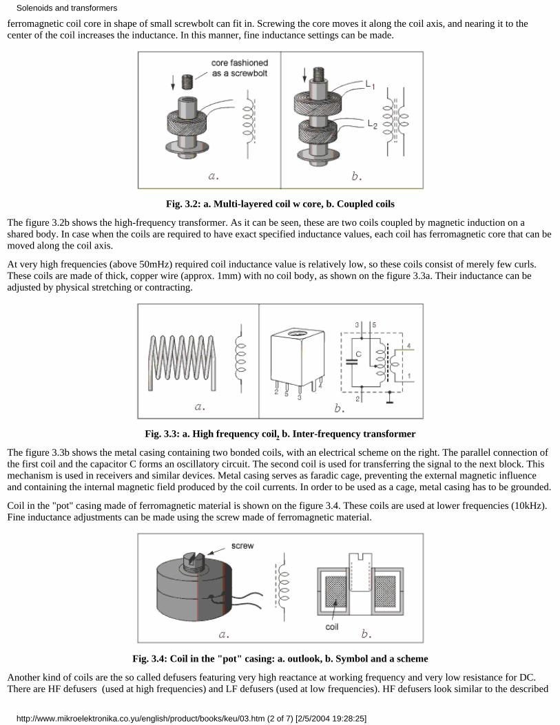
ferromagnetic coil core in shape of small screwbolt can fit in. Screwing the core moves it along the coil axis, and nearing it to thecenter of the coil increases the inductance. In this manner, fine inductance settings can be made.
Fig. 3.2: a. Multi-layered coil w core, b. Coupled coils
The figure 3.2b shows the high-frequency transformer. As it can be seen, these are two coils coupled by magnetic induction on ashared body. In case when the coils are required to have exact specified inductance values, each coil has ferromagnetic core that can bemoved along the coil axis.
At very high frequencies (above 50mHz) required coil inductance value is relatively low, so these coils consist of merely few curls.These coils are made of thick, copper wire (approx. 1mm) with no coil body, as shown on the figure 3.3a. Their inductance can beadjusted by physical stretching or contracting.
Fig. 3.3: a. High frequency coil, b. Inter-frequency transformer
The figure 3.3b shows the metal casing containing two bonded coils, with an electrical scheme on the right. The parallel connection ofthe first coil and the capacitor C forms an oscillatory circuit. The second coil is used for transferring the signal to the next block. Thismechanism is used in receivers and similar devices. Metal casing serves as faradic cage, preventing the external magnetic influenceand containing the internal magnetic field produced by the coil currents. In order to be used as a cage, metal casing has to be grounded.
Coil in the "pot" casing made of ferromagnetic material is shown on the figure 3.4. These coils are used at lower frequencies (10kHz).Fine inductance adjustments can be made using the screw made of ferromagnetic material.
Fig. 3.4: Coil in the "pot" casing: a. outlook, b. Symbol and a scheme
Another kind of coils are the so called defusers featuring very high reactance at working frequency and very low resistance for DC.There are HF defusers (used at high frequencies) and LF defusers (used at low frequencies). HF defusers look similar to the described
Solenoids and transformers
http://www.mikroelektronika.co.yu/english/product/books/keu/03.htm (2 of 7) [2/5/2004 19:28:25]
coils. LF defusers are made with the cores identical to those used with network transformers. Symbol for HF defusers is the one usedfor the previously described coils, while the symbol for LF defusers looks like the one used for coils with core, with bold line or twothin lines instead of the broken line.
3.2 Transformers
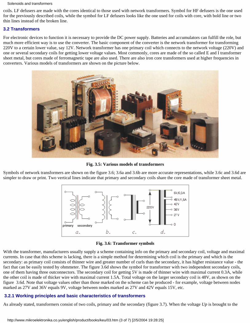
For electronic devices to function it is necessary to provide the DC power supply. Batteries and accumulators can fulfill the role, butmuch more efficient way is to use the converter. The basic component of the converter is the network transformer for transforming220V to a certain lower value, say 12V. Network transformer has one primary coil which connects to the network voltage (220V) andone or several secondary coils for getting lower voltage values. Most commonly, cores are made of the so called E and I transformersheet metal, but cores made of ferromagnetic tape are also used. There are also iron core transformers used at higher frequencies inconverters. Various models of transformers are shown on the picture below.
Fig. 3.5: Various models of transformers
Symbols of network transformers are shown on the figure 3.6; 3.6a and 3.6b are more accurate representations, while 3.6c and 3.6d aresimpler to draw or print. Two vertical lines indicate that primary and secondary coils share the core made of transformer sheet metal.
Fig. 3.6: Transformer symbols
With the transformer, manufacturers usually supply a scheme containing info on the primary and secondary coil, voltage and maximalcurrents. In case that this scheme is lacking, there is a simple method for determining which coil is the primary and which is thesecondary: as primary coil consists of thinner wire and greater number of curls than the secondary, it has higher resistance value - thefact that can be easily tested by ohmmeter. The figure 3.6d shows the symbol for transformer with two independent secondary coils,one of them having three outconnectors. The secondary coil for getting 5V is made of thinner wire with maximal current 0.3A, whilethe other coil is made of thicker wire with maximal current 1.5A. Total voltage on the larger secondary coil is 48V, as shown on thefigure 3.6d. Note that voltage values other than those marked on the scheme can be produced - for example, voltage between nodesmarked as 27V and 36V equals 9V, voltage between nodes marked as 27V and 42V equals 15V, etc.
3.2.1 Working principles and basic characteristics of transformers
As already stated, transformers consist of two coils, primary and the secondary (figure 3.7). When the voltage Up is brought to the
Solenoids and transformers
http://www.mikroelektronika.co.yu/english/product/books/keu/03.htm (3 of 7) [2/5/2004 19:28:25]
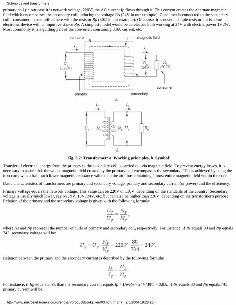
primary coil (in our case it is network voltage, 220V) the AC current Ip flows through it. This current creates the alternate magneticfield which encompasses the secondary coil, inducing the voltage Us (24V in our example). Consumer is connected to the secondarycoil - consumer is exemplified here with the resistor Rp (30© in our example). Of course, it is never a simple resistor but is someelectronic device with an input resistance Rp. A simplest model would be an electric bulb working at 24V with electric power 19.2W.Most commonly it is a guiding part of the converter, consuming 0.8A current, etc.
Fig. 3.7: Transformer: a. Working principles, b. Symbol
Transfer of electrical energy from the primary to the secondary coil is carried out via magnetic field. To prevent energy losses, it isnecessary to assure that the whole magnetic field created by the primary coil encompasses the secondary. This is achieved by using theiron core, which has much lower magnetic resistance value than the air, thus containing almost entire magnetic field within the core.
Basic characteristics of transformers are primary and secondary voltage, primary and secondary current (or power) and the efficiency.
Primary voltage equals the network voltage. This value can be 220V or 110V, depending on the standards of the country. Secondaryvoltage is usually much lower, say 6V, 9V, 15V, 24V, etc, but can also be higher than 220V, depending on the transformer's purpose.Relation of the primary and the secondary voltage is given with the following formula:
where Ns and Np represent the number of curls of primary and secondary coil, respectively. For instance, if Ns equals 80 and Np equals743, secondary voltage will be:
Relation between the primary and the secondary current is described by the following formula:
For instance, if Rp equals 30©, than the secondary current equals Ip = Up/Rp = 24V/30© = 0.8A. If Ns equals 80 and Np equals 743,primary current will be:
Solenoids and transformers
http://www.mikroelektronika.co.yu/english/product/books/keu/03.htm (4 of 7) [2/5/2004 19:28:25]
Transformer power can be calculated by one of the following formulae:
In our example, the power equals:
Everything said up to this point relates to the ideal transformer. Clearly, there is no such thing as losses are inevitable. They are presentdue to the fact that the coil wire exhibits a certain resistance value, which makes the transformer warm up during the work, and the factthat the magnetic field created by the primary does not entirely encompass the secondary coil. This is why the electrical power of thesecondary current has to be lower than the power of the primary current. Their ratio is called efficiency:
For transformers with power measuring hundreds of Watts, efficiency is about µ=0.85, meaning that 85% of the electrical energy takenfrom the network gets to the consumer, while the 15% is lost due to previously mentioned factors in the form of heat. For example, ifelectrical power of the consumer equals Up*Ip = 30W, then the power which the transformer draws from the network equals:
To avoid any confusion here, bear in mind that manufacturers have already taken every measure in minimizing the losses oftransformers and other electronic components and that, practically, this is the top possible efficiency for the present. When acquiring atransformer, you should only take care of the required voltage and the maximal current of the secondary coil. If the salesman cannottell you the exact value of the current, he should be able to tell you the transformer's power. Dividing the values of power and thesecondary voltage gets you the maximal current value for the consumer. Dividing the values of power and the primary voltage gets youthe current that the transformer draws from network, which is important to know when buying the fuse. Anyhow, you should be able tocalculate any value you might need using the appropriate formulae from above.
3.3 Practical examples with coils and transformers
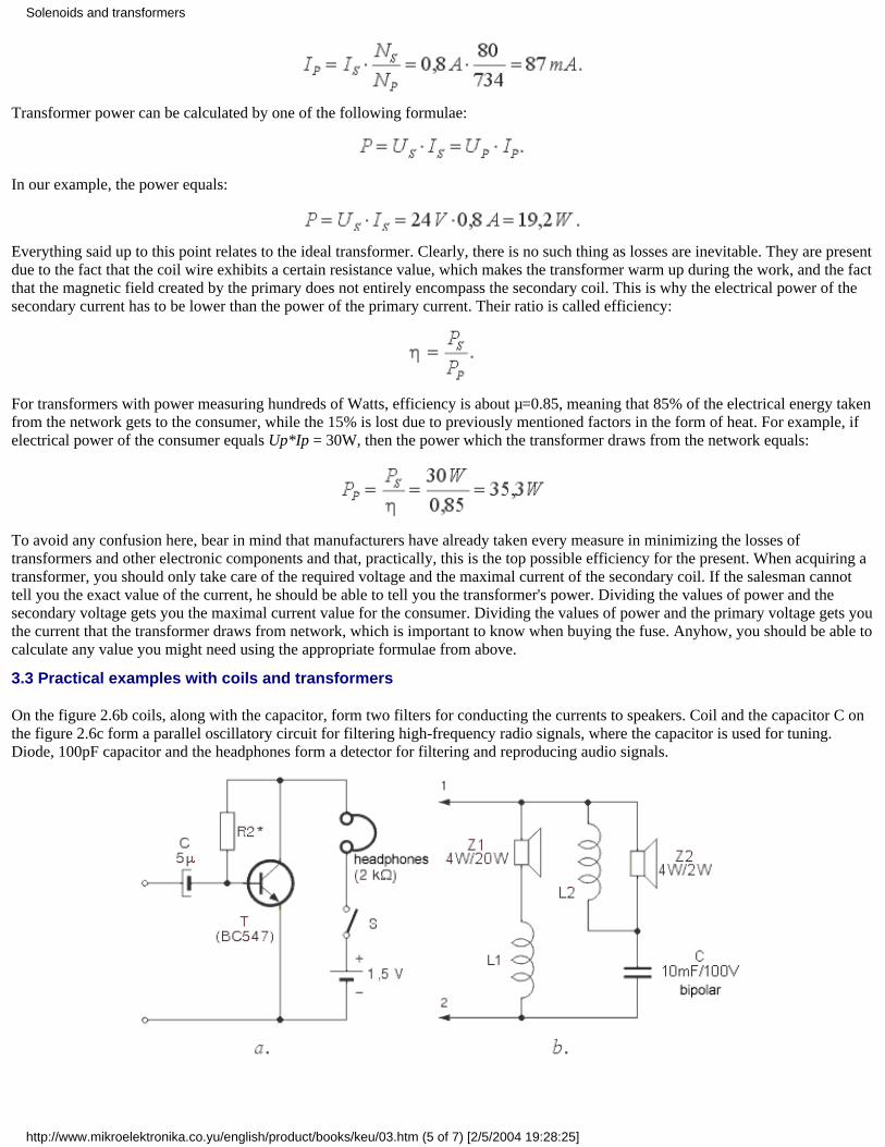
On the figure 2.6b coils, along with the capacitor, form two filters for conducting the currents to speakers. Coil and the capacitor C onthe figure 2.6c form a parallel oscillatory circuit for filtering high-frequency radio signals, where the capacitor is used for tuning.Diode, 100pF capacitor and the headphones form a detector for filtering and reproducing audio signals.
Solenoids and transformers
http://www.mikroelektronika.co.yu/english/product/books/keu/03.htm (5 of 7) [2/5/2004 19:28:25]
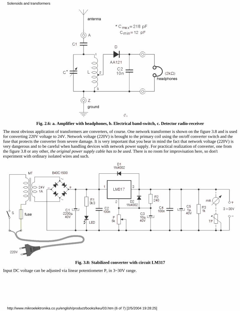
Fig. 2.6: a. Amplifier with headphones, b. Electrical band-switch, c. Detector radio-receiver
The most obvious application of transformers are converters, of course. One network transformer is shown on the figure 3.8 and is usedfor converting 220V voltage to 24V. Network voltage (220V) is brought to the primary coil using the on/off converter switch and thefuse that protects the converter from severe damage. It is very important that you bear in mind the fact that network voltage (220V) isvery dangerous and to be careful when handling devices with network power supply. For practical realization of converter, one fromthe figure 3.8 or any other, the original power supply cable has to be used. There is no room for improvisation here, so don'texperiment with ordinary isolated wires and such.
Fig. 3.8: Stabilized converter with circuit LM317
Input DC voltage can be adjusted via linear potentiometer P, in 3~30V range.
Solenoids and transformers
http://www.mikroelektronika.co.yu/english/product/books/keu/03.htm (6 of 7) [2/5/2004 19:28:25]
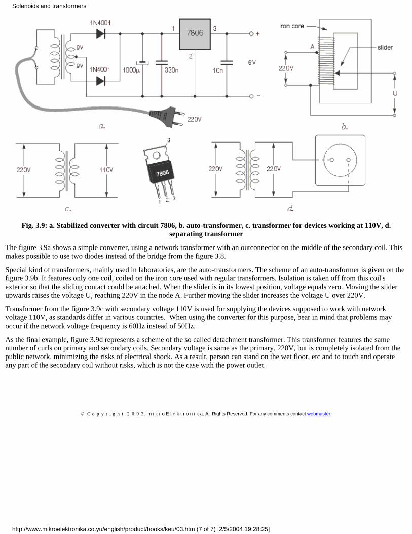
Fig. 3.9: a. Stabilized converter with circuit 7806, b. auto-transformer, c. transformer for devices working at 110V, d.separating transformer
The figure 3.9a shows a simple converter, using a network transformer with an outconnector on the middle of the secondary coil. Thismakes possible to use two diodes instead of the bridge from the figure 3.8.
Special kind of transformers, mainly used in laboratories, are the auto-transformers. The scheme of an auto-transformer is given on thefigure 3.9b. It features only one coil, coiled on the iron core used with regular transformers. Isolation is taken off from this coil'sexterior so that the sliding contact could be attached. When the slider is in its lowest position, voltage equals zero. Moving the sliderupwards raises the voltage U, reaching 220V in the node A. Further moving the slider increases the voltage U over 220V.
Transformer from the figure 3.9c with secondary voltage 110V is used for supplying the devices supposed to work with networkvoltage 110V, as standards differ in various countries. When using the converter for this purpose, bear in mind that problems mayoccur if the network voltage frequency is 60Hz instead of 50Hz.
As the final example, figure 3.9d represents a scheme of the so called detachment transformer. This transformer features the samenumber of curls on primary and secondary coils. Secondary voltage is same as the primary, 220V, but is completely isolated from thepublic network, minimizing the risks of electrical shock. As a result, person can stand on the wet floor, etc and to touch and operateany part of the secondary coil without risks, which is not the case with the power outlet.
Previous page Table of contents Next page
© C o p y r i g h t 2 0 0 3. m i k r o E l e k t r o n i k a. All Rights Reserved. For any comments contact webmaster.
Solenoids and transformers
http://www.mikroelektronika.co.yu/english/product/books/keu/03.htm (7 of 7) [2/5/2004 19:28:25]