eaton wmzt miniature circuit breakers - automationdirect · ecp-66 circuit protection...
TRANSCRIPT

1 - 80 0 - 633 - 0405Circuit ProtectioneCP-66
Prices as of April 16, 2014. Check Web site for most current prices.
Book 3 (14.1)
WMZT Miniature Circuit Breakers
ApplicationsFeeder and Branch Circuit Protection
• Convenience receptacle circuits (internal / external)
• Motor control circuits• Load circuits leaving the equipment
(external)• HACR Equipment (Heating Air Condi-
tioning, Refrigeration)• PLC I/O points• Computers• Power supplies• Control instrumentation• Relays• UPS• Power conditioners
OverviewEaton WMZT miniature circuit breakers offer optimum and efficient protection for branch and control circuits up to 40 amps. The WMZT series is available with C or D trip characteristics in accordance with UL489. These circuit breakers are current limiting, which means they inter-rupt fault currents within one half cycle of the fault. The WMZT series is DIN-rail mountable and can be used in branch circuit applications.
Listings• UL Listed and Recognized under UL 489
Category DIVQ File E7819 Category DKSY2 File E7819 Category DIHS E64983
• CSA 22.2, No. 5 File 245545• CE LVD 2006/95/EC• IEC/EN 60947-2
Features and Benefits• Complete range of UL489 listed DIN rail
mounted miniature circuit breakers up to 40 ampere current rating
• Single pole, two-pole and three pole models
• Current limiting design provides fast short circuit interruption that reduces the let-through energy, which can damage the circuit
• Suitable for branch circuit device protection
• Thermal-magnetic overcurrent protec-tion — two levels of short circuit protection, categorized by C and D curves
C curve magnetic trip point: 5 to 10 times the rated current, typically used for small transformers, pilot devices, etc.
D curve magnetic trip point: 10 to 20 times the rated current, typically used for transformers or loads with very high inductive loads.
• Trip-free design — breaker cannot be defeated by holding the handle in the “ON” position
• Captive screws cannot be lost• SWD (switching duty) rated circuit
breaker — suitable for switching fluorescent lighting loads (In m 20A)
• Fulfills UL 489, CSA C22.2 No.5 and also IEC 60947-2 Standard
• Can also be used in applications for which UL 1077 or CSA C22.2 No.235 are also allowed
• Field installable shunt trip and auxiliary switch subsequent mounting (See Al-lowable Combinations page)
• Module width of only 17.7 mm (per pole)• Contact position indicator (red / green)• 35mm DIN-rail mountable, utilizing
spring clip• Suitable for reverse feed applications

eCP-67Circuit Protectionw w w. a u to m at i o n d i re c t . c o m / c i r c u i t- p ro te c t i o n
Prices as of April 16, 2014. Check Web site for most current prices.
Book 3 (14.1)
Company Information
Terminal Blocks
Power Distribution Blocks
Wiring Accessories
ZIPLink Connection System
Multi-wire Connectors
Sensor Cables and Connectors
M12 Junction Blocks
Panel Interface Connectors
Wiring Duct
Cable Ties
Wire
Flexible Cord
Multi-conductor Flex Cable
Data Cables
Wire Management Products
Power Supplies
DC Converters
Transformers and Filters
Circuit Protection
Tools
Test Equipment
Enclosures
Enclosure Climate Control
Safety: Electrical Components
Safety: Protective Wear
Terms and Conditions
WMZT Miniature Circuit Breakers
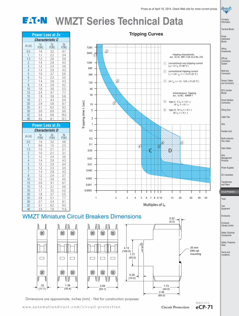
Tripping CharacteristicsEaton WMZT miniature circuit breakers are available with “C” and “D” tripping characteristics.
Type C trip curve: 5 to10 In
C-curve devices are suitable for applications where medium levels of inrush current are expected. Applications include small transformers, lighting, pilot devices, control circuits and coils. C-curve devices provide a medium magnetic trip point.
Type D trip curve: 10 to 20 In
D-curve devices are suitable for applications where high levels of inrush current are expected. The high magnetic trip point prevents nuisance tripping in high inductive applications such as motors, transformers and power supplies.
Eaton WMZT devices are current limiting, which means they interrupt fault currents within one half cycle of the fault. Cur-rent limiting devices offer superior protection by reducing peak let-through current and energy.
0.0005
rTgni
ppi
timt
e]ces[
7200
3600
1200
600
300
120
60
30
10
5
2
1
0.5
0.2
0.1
0.05
0.02
0.005
0.01
0.002
0.001
504030201510987654321
acc. to IEC 60898-1instantaneous tripping
5454
3
12
N
N
1
2
t
nt
N
N
N
N
4
6
N3
I = 1.0 I (T=40 °C )
I = 1.35 I : t < 1 h (T=25 °C )
2.0 I : t = 12- 120 s (T=25 °C )
10 I : t < 0.1 s
20 I : t < 0.1 s
conventional non-tripping current
conventional tripping current
type C: 5 I : t > 0.1 s
type D: 10 I : t > 0.1 s
tripping characteristicacc. to UL 489 / CSA 22.2 No. 235
3
DC
Multiples of In
LabelingThe front of each Eaton WMZT miniature circuit breaker is labeled for positive identification.

1 - 80 0 - 633 - 0405Circuit ProtectioneCP-68
Prices as of April 16, 2014. Check Web site for most current prices.
Book 3 (14.1)
Single-Pole
WMZT - Single-Pole Selection GuideAmpereRating
C Curve Part Number Price D Curve
Part Number Price
0.5 WMZT1CX0
$18.00
WMZT1DX0
$18.00
1 WMZT1C01 WMZT1D011.5 WMZT1CX1 WMZT1DX12 WMZT1C02 WMZT1D023 WMZT1C03 WMZT1D034 WMZT1C04 WMZT1D045 WMZT1C05 WMZT1D056 WMZT1C06 WMZT1D067 WMZT1C07 WMZT1D078 WMZT1C08 WMZT1D0810 WMZT1C10 WMZT1D1013 WMZT1C13 WMZT1D1315 WMZT1C15 WMZT1D1516 WMZT1C16 WMZT1D1620 WMZT1C20 WMZT1D2025 WMZT1C25 WMZT1D2530 WMZT1C30 WMZT1D3032 WMZT1C32 WMZT1D32*40 WMZT1C40 WMZT1D40
* Rated 240VAC
WMZT Series Selection Guide
WMZT - Two-Pole Selection GuideAmpereRating
C Curve Part Number Price D Curve
Part Number Price
0.5 WMZT2CX0
$35.00
WMZT2DX0
$35.00
1 WMZT2C01 WMZT2D011.5 WMZT2CX1 WMZT2DX12 WMZT2C02 WMZT2D023 WMZT2C03 WMZT2D034 WMZT2C04 WMZT2D045 WMZT2C05 WMZT2D056 WMZT2C06 WMZT2D067 WMZT2C07 WMZT2D078 WMZT2C08 WMZT2D0810 WMZT2C10 WMZT2D1013 WMZT2C13 WMZT2D1315 WMZT2C15 WMZT2D1516 WMZT2C16 WMZT2D1620 WMZT2C20 WMZT2D2025 WMZT2C25 WMZT2D2530 WMZT2C30 WMZT2D3032 WMZT2C32 WMZT2D32*40 WMZT2C40 WMZT2D40
* Rated 240VAC
Two-Pole
Note: Eaton parts available for sale to North America locations only.

eCP-69Circuit Protectionw w w. a u to m at i o n d i re c t . c o m / c i r c u i t- p ro te c t i o n
Prices as of April 16, 2014. Check Web site for most current prices.
Book 3 (14.1)
Company Information
Terminal Blocks
Power Distribution Blocks
Wiring Accessories
ZIPLink Connection System
Multi-wire Connectors
Sensor Cables and Connectors
M12 Junction Blocks
Panel Interface Connectors
Wiring Duct
Cable Ties
Wire
Flexible Cord
Multi-conductor Flex Cable
Data Cables
Wire Management Products
Power Supplies
DC Converters
Transformers and Filters
Circuit Protection
Tools
Test Equipment
Enclosures
Enclosure Climate Control
Safety: Electrical Components
Safety: Protective Wear
Terms and Conditions
WMZT - Three-Pole Selection GuideAmpereRating
C Curve Part Number Price D Curve
Part Number Price
0.5 WMZT3CX0
$54.50
WMZT3DX0
$54.50
1 WMZT3C01 WMZT3D011.5 WMZT3CX1 WMZT3DX12 WMZT3C02 WMZT3D023 WMZT3C03 WMZT3D034 WMZT3C04 WMZT3D045 WMZT3C05 WMZT3D056 WMZT3C06 WMZT3D067 WMZT3C07 WMZT3D078 WMZT3C08 WMZT3D08
10 WMZT3C10 WMZT3D1013 WMZT3C13 WMZT3D1315 WMZT3C15 WMZT3D1516 WMZT3C16 WMZT3D1620 WMZT3C20 WMZT3D2025 WMZT3C25 WMZT3D2530 WMZT3C30 WMZT3D3032 WMZT3C32 WMZT3D32*40 WMZT3C40 WMZT3D40
* Rated 240VAC
Three-Pole
WMZT Series Selection Guide
Miniature Circuit Breaker - IECC Curve D Curve
Short Circuit Trip Response 5 - 10 x In 10 - 20 x In
Current Range 0.5 - 40A 0.5 - 40A
Maximum Voltage Ratings - IEC/EN 60947-2
1 pole240 / 415 VAC2 pole
3 poleThermal Tripping Characteristics
Single pole 30°C
Multi-pole 30°C
Interrupt Ratings (At Max Voltage) 15kA
Rated Frequency 50 / 60Hz
Wire Size - WMZTAmpere Rating Cable Size
0.5 - 40One wire 0.75 to 13 mm2 18 to 6 AWG
Two wires 0.75 to 5 mm2 18 to 10 AWG
General Specifications - WMZTLifespan / Endurance M20,000 (1 operation = ON/OFF)
Operating Temperature UL 489, CSA C22.2 No.5 = 40°C IEC 60947-2 = 30°C
Shock (UL 489) 10g 20-25 msHousing Material Nylon
Mounting Position Vertical
WeightOne-Pole 0.3 lb (136g)Two-Pole 0.6 lb (272g)
Three-Pole 0.9 lb (408g)
Tightening Torque - WMZTCable Size Tightening Torque18 - 12 AWG 2.4 N·m 21 lb·in
10 - 8 AWG 2.8 N·m 25 lb·in
6 AWG 4.1 N·m 36 lb·in
Miniature Circuit Breaker - UL / CSAC Curve D Curve
Short Circuit Trip Response 5 - 10 x In 10 - 20 x In
Current Range 0.5 - 40A 0.5 - 40A
Maximum Voltage Ratings - UL / CSA
0.5 - 32A 277 / 480Y
32A 240VAC
Per pole 48VDC
Thermal Tripping Characteristics
Single pole40°C
Multi-pole
Short Circuit Ratings (At Max. Voltage)
1 pole10kA2 pole
3 poleRated Frequency 50 / 60Hz
Note: Eaton does not recommend the use of wire ferrules or crimp-ing terminals. The wire gauges are specified above and in the installation instructions included with each circuit breaker.

1 - 80 0 - 633 - 0405Circuit ProtectioneCP-70
Prices as of April 16, 2014. Check Web site for most current prices.
Book 3 (14.1)
WMZT Series Technical Data
Characteristic C (0.5-20A), 277V
0005
0006
00070008000900001
0001
0051
0002
0003
0004
005
300
400
70000
50000
30000
15000
900
9000
7000
5000
3000
1500
700
500
80000
60000
40000
20000
10000
8000
6000
4000
2000
1000
800
600
C13C10
C 2
C 1,5
C8
C5
C 0.5
C 1
C3C4
C6 , C7
C 15, C 16C 20
Prospective short-circuit current [A]
0005
0006
00070008000900001
0001
0051
0002
0003
0004
005300
400
70000
50000
30000
15000
900
9000
7000
5000
3000
1500
700
500
80000
60000
40000
20000
10000
8000
6000
4000
2000
1000
800
600
C30
C35C40
C32
C25
Prospective short-circuit current [A]
0005
0006
00070008000900001
0001
0051
0002
0003
0004
005
300
400
70000
50000
30000
15000
900
9000
7000
5000
3000
1500
700
500
80000
60000
40000
20000
10000
8000
6000
4000
2000
1000
800
600
D15, D16
D13
D10D8
D2
D1.5
D6,D7
D5
D0.5
D1
D3
D4
D20
Prospective short-circuit current [A]
0005
0006
00070008000900001
0001
0051
0002
0003
0004
005
300
400
70000
50000
30000
15000
900
9000
7000
5000
3000
1500
700
500
80000
60000
40000
20000
10000
8000
6000
4000
2000
1000
800
600
D30
D35
D40
D32
D25
Prospective short-circuit current [A]
Characteristic C (25-40A), 240V
Characteristic D (0.5-20A), 277V Characteristic D (25-40A), 240V
Let-Through Energy
eCP-71Circuit Protectionw w w. a u to m at i o n d i re c t . c o m / c i r c u i t- p ro te c t i o n
Prices as of April 16, 2014. Check Web site for most current prices.
Book 3 (14.1)
Company Information
Terminal Blocks
Power Distribution Blocks
Wiring Accessories
ZIPLink Connection System
Multi-wire Connectors
Sensor Cables and Connectors
M12 Junction Blocks
Panel Interface Connectors
Wiring Duct
Cable Ties
Wire
Flexible Cord
Multi-conductor Flex Cable
Data Cables
Wire Management Products
Power Supplies
DC Converters
Transformers and Filters
Circuit Protection
Tools
Test Equipment
Enclosures
Enclosure Climate Control
Safety: Electrical Components
Safety: Protective Wear
Terms and Conditions
WMZT Series Technical Data
1.77(45.0)
.70(17.7)
1.39(35.4)
2.09(53.1)
1.73(44.0)
2.36(60.0)
0.22(5.5)
0.39(10.0)
4.13(105.0)
35 mmDIN railmounting
Dimensions are approximate, inches (mm) - Not for construction purposes
0.0005
rTgni
ppi
timt
e]ces[
7200
3600
1200
600
300
120
60
30
10
5
2
1
0.5
0.2
0.1
0.05
0.02
0.005
0.01
0.002
0.001
504030201510987654321
acc. to IEC 60898-1instantaneous tripping
5454
3
12
N
N
1
2
t
nt
N
N
N
N
4
6
N3
I = 1.0 I (T=40 °C )
I = 1.35 I : t < 1 h (T=25 °C )
2.0 I : t = 12- 120 s (T=25 °C )
10 I : t < 0.1 s
20 I : t < 0.1 s
conventional non-tripping current
conventional tripping current
type C: 5 I : t > 0.1 s
type D: 10 I : t > 0.1 s
tripping characteristicacc. to UL 489 / CSA 22.2 No. 235
3
DC
Multiples of In
Power Loss at InCharacteristic C
In [A] 1p P[W]
2p P[W]
3p P[W]
0.5 1.6 3.2 4.71 1.1 2.2 3.4
1.5 1.3 2.6 3.92 1.4 2.8 4.33 1.2 2.4 3.64 1.4 2.9 4.35 1.9 3.7 5.66 1.2 2.3 3.57 1.4 2.8 4.38 1.4 2.8 4.2
10 1.8 3.6 5.313 2.4 4.7 7.115 1.9 3.8 5.616 2.1 4.3 6.420 2.9 5.8 8.725 3.1 6.2 9.330 3.0 6.0 9.032 3.4 6.8 10.240 4.0 8.1 12.1
Power Loss at InCharacteristic D
In [A] 1p P[W]
2p P[W]
3p P[W]
0.5 1.6 3.2 4.81 0.8 1.5 2.3
1.5 1.0 2.1 3.12 1.0 2.1 3.13 1.2 2.4 3.64 1.4 2.9 4.35 1.5 2.9 4.46 1.2 2.3 3.57 1.4 2.8 4.38 1.2 2.4 3.7
10 1.5 3.0 4.513 2.0 4.1 6.115 1.5 3.1 4.616 1.7 3.5 5.220 1.8 3.7 5.525 2.6 5.1 7.730 2.7 5.4 8.132 3.1 6.2 9.340 3.9 7.8 11.6
WMZT Miniature Circuit Breakers Dimensions
Tripping Curves
1 - 80 0 - 633 - 0405Circuit ProtectioneCP-72
Prices as of April 16, 2014. Check Web site for most current prices.
Book 3 (14.1)
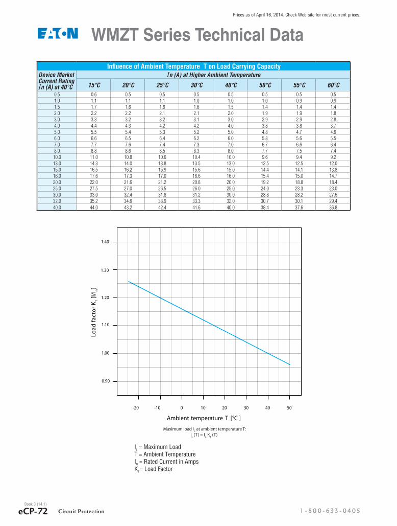
Influence of Ambient Temperature T on Load Carrying CapacityDevice Market Current Rating In (A) at 40°C
In (A) at Higher Ambient Temperature
15°C 20°C 25°C 30°C 40°C 50°C 55°C 60°C0.5 0.6 0.5 0.5 0.5 0.5 0.5 0.5 0.51.0 1.1 1.1 1.1 1.0 1.0 1.0 0.9 0.91.5 1.7 1.6 1.6 1.6 1.5 1.4 1.4 1.42.0 2.2 2.2 2.1 2.1 2.0 1.9 1.9 1.83.0 3.3 3.2 3.2 3.1 3.0 2.9 2.9 2.84.0 4.4 4.3 4.2 4.2 4.0 3.8 3.8 3.75.0 5.5 5.4 5.3 5.2 5.0 4.8 4.7 4.66.0 6.6 6.5 6.4 6.2 6.0 5.8 5.6 5.57.0 7.7 7.6 7.4 7.3 7.0 6.7 6.6 6.48.0 8.8 8.6 8.5 8.3 8.0 7.7 7.5 7.4
10.0 11.0 10.8 10.6 10.4 10.0 9.6 9.4 9.213.0 14.3 14.0 13.8 13.5 13.0 12.5 12.5 12.015.0 16.5 16.2 15.9 15.6 15.0 14.4 14.1 13.816.0 17.6 17.3 17.0 16.6 16.0 15.4 15.0 14.720.0 22.0 21.6 21.2 20.8 20.0 19.2 18.8 18.425.0 27.5 27.0 26.5 26.0 25.0 24.0 23.3 23.030.0 33.0 32.4 31.8 31.2 30.0 28.8 28.2 27.632.0 35.2 34.6 33.9 33.3 32.0 30.7 30.1 29.440.0 44.0 43.2 42.4 41.6 40.0 38.4 37.6 36.8
WMZT Series Technical Data
50403020100-10-20
0.90
1.40
1.30
1.20
1.10
1.00
Ambient temperature T [°C ]
Maximum load IL at ambient temperature T:IL (T) = In KT (T)
rotcaf daoLK T
/I[ I n]
IL = Maximum LoadT = Ambient TemperatureIN = Rated Current in AmpsKT = Load Factor

eCP-73Circuit Protectionw w w. a u to m at i o n d i re c t . c o m / c i r c u i t- p ro te c t i o n
Prices as of April 16, 2014. Check Web site for most current prices.
Book 3 (14.1)
Company Information
Terminal Blocks
Power Distribution Blocks
Wiring Accessories
ZIPLink Connection System
Multi-wire Connectors
Sensor Cables and Connectors
M12 Junction Blocks
Panel Interface Connectors
Wiring Duct
Cable Ties
Wire
Flexible Cord
Multi-conductor Flex Cable
Data Cables
Wire Management Products
Power Supplies
DC Converters
Transformers and Filters
Circuit Protection
Tools
Test Equipment
Enclosures
Enclosure Climate Control
Safety: Electrical Components
Safety: Protective Wear
Terms and Conditions
WMZT Series Accessories
WMZT Accessory Data
Part Number Circuit Diagram Electrical CharacteristicsWireSize
(Solid and Stranded)Terminal
Tightening Torquemm² AWG N·m lb·in
WMZTAUX
21
13
22 14
Rated for general use, 2A at 230 VAC / 0.5 A at 24/110 VDC 50 / 60 Hz
(1) 0.5 to 2.5 (2) 0.5 to (2) 2.5
(1) 20 to 14 (2) 18 to (2) 14
1.2 10.6
WMZSAUXTRIP See WMZSAUXTRIP diagrams on next page
1 SPDT auxiliary contact and 1 SPDT alarm contact that can be configured and used as an auxiliary contact, rated for general use, 2A at 200 VAC / 0.5 A at 24/110 VDC 50 / 60 Hz
(1) 0.5 to 2.5 (2) 0.5 to (2) 1.5
(1) 18 to 14 (2) 18 to (2) 16
0.8 7.0
WMZTST415
C2
C1110 - 415 VAC, 110 - 230 VDC operating range 0.5 A at 110 VAC, 2A at 415 VAC 0.5 A at 110 VDC, 1.1 A at 230 VAC (1) 1 to 6
(2) 1 to (2) 6
(1) 18 to 10 (2) 18 to (2) 10
2.8 25.0
WMZTST11012 - 110 VAC, 12 - 60 VDC operating range 0.5 A at 12 VAC, 4.4 A at 110 VAC 0.5 A at 12 VDC, 2.4 A at 60 VDC
WMZT Accessories Selection Guide
Part Number Description Contacts Module Width
Module Weight Price
WMZTAUX• 1 NO / 1 NC Contact • Installs on left side of WMZT or Shunt Trip • Maximum one per WMZT (489) Device • Switches when WMZT is tripped electrically or manually
1 NO / 1 NC
0.35” (8.9 mm) 0.15 lb (68g)
$16.00
WMZSAUXTRIP
• Two Form C (One set Changeover) contacts, 1 SPDT aux / 1 SPDT alarm • Small selector screw changes mode • Installs on left side of WMZS, WMZT or shunt trip • Auxilary contacts switch when WMZS or WMZT is tripped electrically or manually. • Trip indicating contact switches only when WMZS or WMZT is tripped electrically.
(2) Form C $20.00
Part Number Description Trip Voltage Module Width
Module Weight Price
WMZTST415• Allows remote trip of WMZT • Installs on left side of WMZT
110 - 415 VAC110 - 230 VDC 0.69“
(17.5 mm) 0.28 lb (127g)$28.50
WMZTST110 12 - 110 VAC12 - 60 VDC
$28.50
WMZSAUXTRIP Alarm/Aux Contact
WMZTAUX Auxiliary Contact
WMZTSTxxx Shunt Trip
Allowable Combinations of Accessories
WMZTMiniature
CircuitBreaker
or
WMZSAUXTRIPAuxilary /
AlarmSwitch
WMZTAUXStandardAuxilary
WMZTSTxxxShunt
Trip
or
WMZSAUXTRIPAuxilary /
AlarmSwitch
WMZTAUXStandardAuxilary
WMZTMiniature
CircuitBreaker
Field Mountable Accessories
• Auxiliary switch• Alarm switch• Shunt trip- No tools required for mounting

1 - 80 0 - 633 - 0405Circuit ProtectioneCP-74
Prices as of April 16, 2014. Check Web site for most current prices.
Book 3 (14.1)
WMZT Series Accessories
WMZPLK
Lockout Attachment
Additional WMZT Accessories
Part Number Description Weight Price
WMZPLKLockout attachment for Eaton WMZS series supplementary protectors and WMZT mini circuit breakers, suitable to prevent unauthorized activation of a de-energized circuit, accepts lock shackles up to 9/32 in. (7.1 mm) in diameter Qty: 5 pieces
0.10 lb (45g) $30.50
Lockout Attachment
1.94(49.3)2.39
(60.7)2.75
(69.9)
.35(8.9)
2.82(71.6)
.16(4.1)
.20(5.1)
.21(5.3)
.23(5.8)
1.95(49.5)
3.15(80.0)
1.77(45.0)
.63(16.0)
.16(4.1)
WMZSAUXTRIP
1.77(45.0)
3.15(80.0)
0.22(5.5)
1.73(44.0)
2.36(60.0)
0.35(8.8)
35 mmDIN railmounting
WMZTAUX
1.77(45.0)
.70(17.7)
1.73(44.0)
2.36(60.0)
0.22(5.5)
1.77(45.0)
0.39(10.0)
35 mmDIN railmounting
WMZTSTxxx
Accessories Dimensions
.19” - .28”(5.0 - 7.1mm)
WMZPLK Installation
Dimensions are approximate, inches (mm) - Not for construction purposes
1 N 1.11 4.11
2 1.121.14 4.12
4.14N
OFF1 N 1.11 4.11
2 1.121.14 4.12
4.14N
SEL
ON OFFTRIP
1 N 1.11
2 1.121.14
N
4.11
4.124.14
1 N 1.11
2 1.121.14
N
4.11
4.14
4.12
4.11
4.14
4.12
SEL
ON OFFTRIP
1 N 1.11 4.11
2 1.12 4.12N
1.14 4.14
OFF1 N 1.11 4.11
2 1.12 4.12N
1.14 4.14
contact 4.xx in Auxilary modecontact 1.xx in Auxilary mode
contact 4.xx in Alarm modecontact 1.xx in Auxilary mode
Manual orElectrical Trip
Manual Trip
Electrical TripWMZSAUXTRIP Diagrams
eCP-75Circuit Protectionw w w. a u to m at i o n d i re c t . c o m / c i r c u i t- p ro te c t i o n
Prices as of April 16, 2014. Check Web site for most current prices.
Book 3 (14.1)
Company Information
Terminal Blocks
Power Distribution Blocks
Wiring Accessories
ZIPLink Connection System
Multi-wire Connectors
Sensor Cables and Connectors
M12 Junction Blocks
Panel Interface Connectors
Wiring Duct
Cable Ties
Wire
Flexible Cord
Multi-conductor Flex Cable
Data Cables
Wire Management Products
Power Supplies
DC Converters
Transformers and Filters
Circuit Protection
Tools
Test Equipment
Enclosures
Enclosure Climate Control
Safety: Electrical Components
Safety: Protective Wear
Terms and Conditions
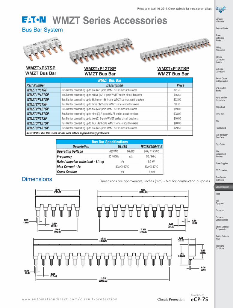
WMZT Series AccessoriesBus Bar System
WMZT Bus BarPart Number Description Price WMZT1P6TSP Bus Bar for connecting up to six (6) 1-pole WMZT series circuit breakers $8.50
WMZT1P12TSP Bus Bar for connecting up to twelve (12) 1-pole WMZT series circuit breakers $15.50
WMZT1P18TSP Bus Bar for connecting up to Eighteen (18) 1-pole WMZT series circuit breakers $23.00
WMZT2P6TSP Bus Bar for connecting up to three (3) 2-pole WMZT series circuit breakers $9.50
WMZT2P12TSP Bus Bar for connecting up to six (6) 2-pole WMZT series circuit breakers $19.00
WMZT2P18TSP Bus Bar for connecting up to nine (9) 2-pole WMZT series circuit breakers $28.00
WMZT3P6TSP Bus Bar for connecting up to two (2) 3-pole WMZT series circuit breakers $10.00
WMZT3P12TSP Bus Bar for connecting up to four (4) 3-pole WMZT series circuit breakers $20.00
WMZT3P18TSP Bus Bar for connecting up to six (6) 3-pole WMZT series circuit breakers $29.50
Note: WMZT Bus Bar is not for use with WMZS supplementary protectors.
Dimensions
WMZTxP6TSP WMZT Bus Bar
Dimensions are approximate, inches (mm) - Not for construction purposes
WMZTxP12TSP WMZT Bus Bar
WMZTxP18TSP WMZT Bus Bar
Bus Bar SpecificationsDescription UL489 IEC/EN60947-2
Operating Voltage 480VAC 96VDC 240 / 415 VAC
Frequency 50 / 60Hz n/a 50 / 60Hz
Rated impulse withstand - Uimp n/a 9.5 kV
Max Current - Ie 80A @ 40°C 80A @ 30°C
Cross Section n/a 16 mm2

1 - 80 0 - 633 - 0405Circuit ProtectioneCP-76
Prices as of April 16, 2014. Check Web site for most current prices.
Book 3 (14.1)
WMZT3PSHROUD Bus Bar Shroud
WMZT35EXT Wiring Lug
WMZT35EXT - SpecificationsDescription UL489 IEC/EN60947-2
Operating Voltage 480VAC 96VDC 240 / 415 VAC
Frequency 50 / 60Hz n/a 50 / 60HzRated impulse withstand - Uimp
n/a 9.5 kV
Max Current - Ie 80A @ 40°C 80A @ 30°C
#2 - 14 AWG 2.5 - 35 mm2
0.56 in 14mm
WMZT35EXT - Tightening TorqueTested Acc. To Cable Size Tightening Torque
UL 486A #14 AWG M 2.3 N·m (20 lb·in)UL 486B #8 - 12 AWG M 2.8 N·m (25 lb·in)UL 486E #6 - 1 AWG 4 N·m (35 lb·in)
WMZT Series AccessoriesBus Bar Accessories
5.00(127.0)
5.98(152.0)
WMZT35EXT
WMZT3P12T
WMZT3PSHROUD
WMZT35EXT WMZT35EXT
Dimensions are approximate, inches (mm) - Not for construction purposes
2.82(71.6)
0.53(13.5)
0.24(6.1)
0.12(3.0)
1.22(31.1)
0.64(16.2)
0.28(7.0)
0.69(17.6)
0.51(13.0)
1.90(48.2)0.69
(17.6)
0.14(3.6)
0.94(24.0)
WMZT Bus Bar AccessoriesPart Number Description Price WMZT3PSHROUD Bus Bar Shroud - covers for unused bus bar terminals, (10) 3-terminal covers per package $22.00
WMZT35EXT Wiring Lug, 35mm (2 - 14 AWG), 3 lugs per package $26.00
Dimensions
WMZT3PSHROUD
WMZT35EXT