eaton fuller heavy-duty transmissions trig2400 · note: the 5/32 inch dot tubing has an internal...
TRANSCRIPT

Installation Guide
Eaton Fuller® Heavy-Duty TransmissionsTRIG2400June 2007
FR-11210B FR-12210B FR-13210B FR-14210B FR-15210B FR-9210B FRF-11210B FRF-12210B FRF-13210B FRF-14210B FRF-15210B FRF-9210B FRO-11210B
FROF-11210B FROF-11210C FROF-12210B FROF-12210C FROF-13210B FROF-13210C FROF-14210B FROF-14210C FROF-15210B FROF-15210C FROF-16210B FROF-16210C
FRO-11210C FRO-12210B FRO-12210C FRO-13210B FRO-13210C FRO-14210B FRO-14210C FRO-15210B FRO-15210C FRO-16210B FRO-16210C FRO-17210C FRO-18210C


Table of ContentsTable of Contents
Transmission Specifications
Transmission Nomenclature ...................................................................................................................................... 1Lubrication Requirements .......................................................................................................................................... 4
Interface Features
Air Specifications ....................................................................................................................................................... 6Shifters ...................................................................................................................................................................... 9Switches* ................................................................................................................................................................ 10Power Take Off Openings ......................................................................................................................................... 13Output Shaft Spline .................................................................................................................................................. 15
Appendix
Transmission Dimensions - Side View* ................................................................................................................... 22Shift Bar Housing - Standard Control ....................................................................................................................... 24Design Remedies for Shift Lever Jumpout ............................................................................................................... 29Optional Internal Cooler - Side View.......................................................................................................................... 31

Transmission Specifications
1
Transmission Nomenclature
Model Designation NomenclatureFR/FRO-1X210C
Ratios and StepsTen Speed Models
Gear Position FR-1X210B FRO-1X210B FRO-1X210C FRO-17210C &18210C
Ratio Step In%
Ratio Step In%
Ratio Step In%
Ratio Step In%
10 1.00 0.75 0.74 0.74
9 1.34 34 1.00 34 1.00 35 1.00 35
8 1.81 35 1.36 35 1.38 38 1.38 38
7 2.45 35 1.83 35 1.90 38 1.90 38
6 3.32 35 2.48 35 2.59 37 2.64 39
5 4.46 35 3.34 35 3.62 40 3.62 37
4 5.97 34 4.46 34 4.90 35 4.90 35
3 8.09 35 6.05 35 6.75 38 6.75 38
2 10.95 35 8.19 35 9.29 38 9.29 38
1 14.80 35 11.06 35 12.69 37 12.94 39
HI Rev 3.63 2.72 2.81 2.81
Lo Rev 16.21 12.12 13.75 13.75
Overall Ratio 14.80 14.80 17.17 17.51
Fuller Roadranger Twin Countershaft
F R O 1 X - 2 1 0 C
Ratio SetForward SpeedsDesign Level
1/100 Times Nominal Torque CapacityOverdrive

Transmission Specifications
2
Installation Length
Transmission Dry Weight in kg [lbs.]
Transmission Center of Gravity Location
Transmission Inertia (In Neutral)
Oil Capacity and Fill
All Models & Series
From the Front Face of a Standard#1 Clutch Housing to the Front Face Of End Yoke in mm. [inch]
759.5 [29.9]
Series 900-1400 1500-1700
Transmission Weight 268 [589] 268 [589] 272 [599] 272 [599]
SAE #1 Aluminum Clutch Housing Weight
10.4 [23] 10.4 [23]
SAE #1 Cast Iron Clutch Housing Weight
34.5 [76] 34.5 [76]
Total Transmission Weight With Aluminum Clutch Housing
278 [612] 282 [622]
Total Transmission Weight With Cast Iron Clutch Housing
302 [665] 306 [675]
with SAE No. 1 Aluminum Clutch Housing Less Shift Tower
Coordinates Viewed From Measured From Direction Values In mm [inch]
Longitudinal Left Side Front Face of Main Case Rearward 251 [9.88]
Vertical Left Side Mainshafts Center Line Upward 25.7 [1.01]
Lateral Rear Mainshafts Center Line Left 0.0 [0.0]
Inertia in kg. m [ft.-lb. sec²] .13 [.093]
Nominal Oil Volume In liters [pints] 11.1 [23.5]
Oil Fill OEM To The Bottom Edge Of Filter Plug Hole
Transmission Specifications
Transmission Specifications
3
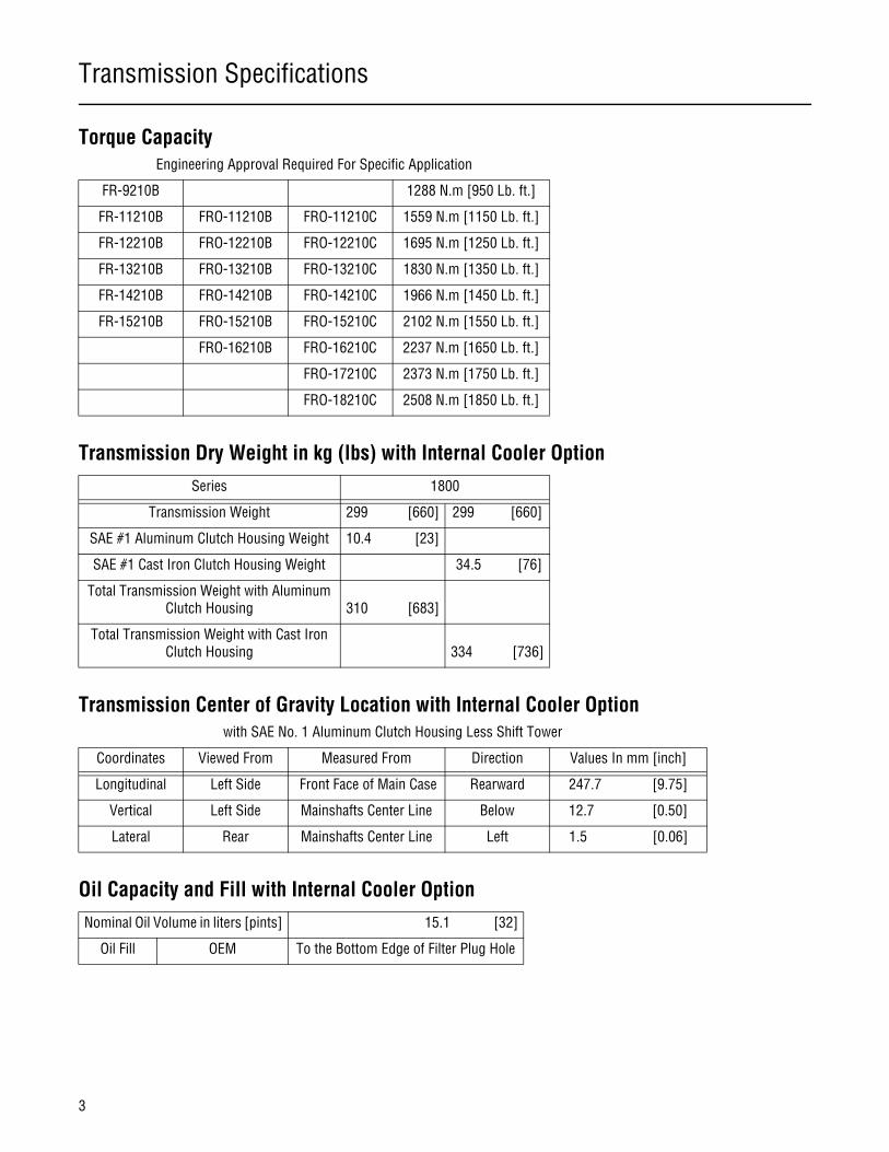
Torque Capacity
Transmission Dry Weight in kg (lbs) with Internal Cooler Option
Transmission Center of Gravity Location with Internal Cooler Option
Oil Capacity and Fill with Internal Cooler Option
Engineering Approval Required For Specific Application
FR-9210B 1288 N.m [950 Lb. ft.]
FR-11210B FRO-11210B FRO-11210C 1559 N.m [1150 Lb. ft.]
FR-12210B FRO-12210B FRO-12210C 1695 N.m [1250 Lb. ft.]
FR-13210B FRO-13210B FRO-13210C 1830 N.m [1350 Lb. ft.]
FR-14210B FRO-14210B FRO-14210C 1966 N.m [1450 Lb. ft.]
FR-15210B FRO-15210B FRO-15210C 2102 N.m [1550 Lb. ft.]
FRO-16210B FRO-16210C 2237 N.m [1650 Lb. ft.]
FRO-17210C 2373 N.m [1750 Lb. ft.]
FRO-18210C 2508 N.m [1850 Lb. ft.]
Series 1800
Transmission Weight 299 [660] 299 [660]
SAE #1 Aluminum Clutch Housing Weight 10.4 [23]
SAE #1 Cast Iron Clutch Housing Weight 34.5 [76]
Total Transmission Weight with Aluminum Clutch Housing
310 [683]
Total Transmission Weight with Cast Iron Clutch Housing
334 [736]
with SAE No. 1 Aluminum Clutch Housing Less Shift Tower
Coordinates Viewed From Measured From Direction Values In mm [inch]
Longitudinal Left Side Front Face of Main Case Rearward 247.7 [9.75]
Vertical Left Side Mainshafts Center Line Below 12.7 [0.50]
Lateral Rear Mainshafts Center Line Left 1.5 [0.06]
Nominal Oil Volume in liters [pints] 15.1 [32]
Oil Fill OEM To the Bottom Edge of Filter Plug Hole

Transmission Specifications
4
Transmission Specifications
Lubrication Requirements
Proper lubrication procedures are the key to a good all around maintenance program.
Eaton Fuller Transmission are designed so that the internal parts operate in an oil circulating bath created by the motion of the gears and shafts.
Thus, all parts are amply lubricated if these procedures are closely followed:
1. Maintain oil level.
2. Inspect regularly.
3. Follow maintenance interval chart.
4. Use the correct grade and type of oil.
5. Buy from a reputable dealer.
Operating Temperatures
Transmissions must not be operated at temperatures above 250°F [120°C]. Operation at temperatures above 250°F [120°C] caus-es loaded gear tooth temperatures to exceed 350°F [177°C] which will ultimately destroy the heat treatment of the gears. If the elevated temperature is associated with an unusual operating condition that will recur, a cooler should be added, or the capacity of the existing cooling system increased.
The following conditions in any combination can cause operating temperatures over 250°F [121°C].
• Operating consistently at slower speeds
• High ambient temperatures
• Restricted air flow around transmission
• High horsepower
• Use of engine retarder
Transmission coolers must be used to reduce operating temperatures when the above conditions are encountered.
Note: For addition lubrication information, see TCMT-0021.

Transmission Specifications
5
Proper Oil Level
Make sure oil is level with the filler opening. Because you can reach oil with your finger does not mean oil is at proper level. (Oneinch of oil level is about one gallon of oil.)
When adding oil, types and brands of oil should not be mixed because of possible incompatibility.
Transmission Operating Angles
If the transmission operating angle is more than 12 degrees, improper lubrication will occur. The operating angle is the transmis-sion mounting angle in the chassis plus the percent of upgrade (expressed in degrees).
For operating angles over 12 degrees, the transmission must be equipped with an oil pump or cooler kit to insure proper lubrica-tion.
Recommended Lubricant Types and Application*
See Form TCMT-0019, Eaton Fuller heavy duty and mid range transmissions "Lubrications Requirements".
WARNING: Do not use EP oils in the Transmissions!
Transmission Operating Limits
Contact Eaton Applications Engineering for the correct applications for approval.
Transmission Application Approval Request
Contact Eaton Applications Engineering for the correct application approval form.
Improper Oil LevelHole Proper Oil LevelHole

Interface Features
6
Interface Features
Air Specifications
Master Valve: Same As Current Product
Vehicle Air Supply Requirement
Air Control Module Port Identification
* Transmission must have an uninterrupted air supply to assure proper performance for all operating conditions. A 3/8" O.D. sup-ply air line size or larger is recommended.
Note: Air additives such as alcohol or deicer should not be permitted to enter the air supply. Additives could cause damage to air system components which could lead to degraded transmission performance.
Thread Size 1/2"-13 UNC
Jam Nut Across Flats Dimension MM. [inch] 19.05 [0.75]
Air Pressure, kPA [PSI] * 620-896 [90-130]
Air Type Clean and Dry
Air Supply Port (IN) SAE 3/8"-18 NPTF Pipe Thread
Air Supply Port Location (IN) Refer to Appendix "Shift Bar Housing"
Pilot (P) SAE 1-16"-27 NPTF Pipe Thread
Pilot Port Location (P) Refer to Appendix "Shift Bar Housing"
Port Description Size
P Range Pilot 1/16"-27 PTF
S Source Air 517-586 kPA [75-85 PSI] 1/16"-27 PTF
H High Range Air Cylinder Pressure 1/16"-27 PTF
L Low Range Air Cylinder Pressure 1/16"-27 PTF
IN Air Supply Port 3/8"- 18 PTF
F Filtered Unregulated Air 1/16"-27 PTF

Interface Features
7
Air Fittings
Air Lines
Available Options
(per D.O.T./FMVSS 106)
Type Straight Push-In
Material Brass
Threads 1/16" - 27 PTF-1 Short
Hex Head Size mm [inch] 9.65 [0.38]
Thread Sealant Yes
(per D.O.T./FMVSS 106)
Size, mm [inch] 4.0 [5/32]
Material Nylon
Colors Black (P Port)
Red (S Port)
Models FR-XX210B FRO-1X210B FRO-1X210C
Options Series 900-1400 1100-1400 1500-1600 1100-1400 1500-1700 1800
Integral Oil Pump Option Option Std. Option Std. Option
Thru-Shaft PTO Option Option Option Option Option Option
Neutral Switch Provision Std. Std. Std. Std. Std. Std.
Neutral Switch Option Option Option Option Option Option
Reverse Switch Provision Std. Std. Std. Std. Std. Std.
Reverse Switch Option Option Option Option Option Option
FR Shift Bar Housing Std. N/A N/A N/A N/A N/A
FRO Shift Bar Housing (+) N/A Std. Std. Std. Std. Std.
FR Forward Shift Bar Housing Option N/A N/A N/A N/A N/A
FRO Forward Shift Bar Housing (+)
N/A Option Option Option Option Option
(+) with an "X" mechanism to maintain standard progressive "H" shift pattern.
Internal Cooler Option Option Option Option Option Option

Interface Features
8
Interface Features
Driver Controlled Main Differential Lock Applications or Controlled Traction Differentials
The following lists the recommended practice for single and tandem drive axles with driver controlled main differential lock appli-cations or controlled traction differentials (CTD).
1. Connections are permitted for signal purposes only. No connections are allowed that will use air to power any device.
2. Signal purposes are defined as devices that do not consume any significant volume of air, more than 32.77 cc.568 MPa (2.0 cubic inches @ 85 PSIG) of air to fill and actuate these devices including connecting plumbing paraphernalia.
3. Maximum connecting line size is 5/32 inch O.D (.096 inch I.D.), such as our DOT air tubing used for connecting the Roadranger Shift Knob to the transmission.
Note: The 5/32 inch DOT tubing has an internal volume of .0869 cubic inch per foot of length which equates to 11.5 feet of length per cubic inch of volume.
A potential source for a relay valve for use with the traction control is:Humphrey ProductsP.O. Box 2008Kalamazoo, MI 49003Phone 269-381-5500 (Fax 269-381-4113)
Humphrey Products offers a 1/4" orifice 3-way normally open pilot valve (part number 250A-3-11-21A-VAI (-20 versus -21A if a base is not needed)) which should be ordered with a Viton elastomer seal. This valve has a volume capacity on the pilot side of less that 0.5 cubic inches.
Supply air to the inlet of the normally open pilot valve should be from the same vehicle air source as used by the transmission. The outlet of the valve should be plumbed to the air supply for the traction control system. Use a 5/32 O.D. DOT tubing air line from the transmission air module high range cylinder port labeled "H" (air module top right-hand side near the air supply port) to the valve pilot port. Therefore, air will be permitted to flow only when either high range or synchro-saver modes are not in effect.
Warning: Equivalent 6 & 7 product models are plumbed such that a normally closed valve is used and pilot air is supplied from the low range port "L" on the slave valve. Therefore, do not use the same model valve as used by the 6 & 7 series product and do not use the pilot signal from the " L" port on the FR Series air module. This change is due to the use of a synchronizer protection device. Anytime the transmission is in gear, either high or low range there will be pressure in the "L" port on the FR Series air module.

Interface Features
9
Shifters
Shift Tower Options**
*See Appendix** Same as current towers, except metric mounting screws.*** Same as 6 and 7 series products.
Shift Pattern
All models will have standard progressive "H" shift pattern.
Ten Speeds
Shift ControlsNote: For Shift Controls, 5.5 - 6.5:1 Mechanical Advantage is Recommended.
* Same as current controls, except metric mounting screws.
** Shift knob threads are 1/2-13 inch.
***Use the appropriate ratios (Appendix: Shift Levers) for computing the in-cab shift knob envelope of various tower and shift lever combinations.
Tower Locations* Standard Forward
Tower Type** Low Mid High
Fore/Aft Locations From Front of Clutch Housing [in} 17.07*** 14.54***
Remote Controls* SRC LRC RLC
Designation Single Rod Control Low Remote Control Remote Lever Control
Shift Lever*** Same as 6 & 7 series products **
Lever Isolator Same as 6 & 7 series products

Interface Features
10
Interface Features
Switches*
* Provisions are standard, switches are optional.** See Appendix.*** For actuation characteristics see the switch drawings on pages 11 & 12.
WARNING: This switch should not be the sole source means of detecting neutral.
Location in Shift Bar Housing In left rear quadrant **
Supply Voltage 12 and 24 volts
Type Normally open (closed and reverse)
Reverse*** Connector type Packard weather-pack (connector p/n 120157952 with 12124582 (M) terminal and 12010293 cable seal (or equivalent)
Threads M14X2.00
Wrench Size 22 mm
Location in Shift Bar Housing At the rear on center**
Supply Voltage 12 and 24 volts
Type Normally Closed (closed in neutral)
Neutral *** Connector type Packard weather-pack (connector p/n 12015378 with 12124582 (M) terminal and 12010293 cable seal (or equivalent)
Threads M16x1.50
Wrench Size 22 mm

Interface Features
11
Electronic Speed Sensor - Push In
Note: Need both Packard Assembly and Packard Sockets for proper wiring harness interface.
Reverse Switch
Notes:
1. Switch to be received with O-ring, Eaton No. 5568504.
2. Switch mates with Packard Electric weather pack connector number 12015792 with a 12124582(M) terminal and 12010293 cable seal or equivalent.
3. Switch makes contact within this range.
Eaton Part Number A-6724 A-6736
Output Type Single Dual
Packard Connector Information to Mate to Eaton Sensor
**Packard Assembly Number 12162193 12162188
*Packard Connector Body 12162192 12162187
*Packard Connector Seal 12040750 12040756
*Packard Cable Seal 12040751 12040757
**Packard Socket Number (Quantity)
12124075 (2) 12124075 (4)
*Used To Make Packard Assembly **Need both Packard Assembly andPackard Sockets for proper wiring harness interface.

Interface Features
12
Interface Features
Neutral Switch
Notes:
1. Switch to be received with O-ring, Eaton NO. 5568510.
2. Switch mates with Packard Electric weather pack connector number 12015378 with a 12124582(M) terminal and 12010293 cable seal or equivalent.
3. Switch breaks contact within this range and remains open to flush.

Interface Features
13
Power Take Off Openings
*See Appendix: Transmission Dimensions - End and Side Views.
PTO Drive Gear Information
*3/4-16 Threaded Sensor Rear Bearing Cover Available Upon Request.
Type Description Data
Six Bolt Mounting surface’s angle with horizon-tal in degrees *:
57 (rotated at 12 deg. C.W. from current products)
(Standard) Center line’s horizontal distance in mm [inch]*:
10.43 [264.9]
Mounting bolt thread Metric, M10x1.50
Eight Bolt Mounting surfaces angle with horizon-tal in degrees*:
0 (same as current products)
Standard Center lines horizontal distance in mm [inch] *:
10.43 [264.9]
Mounting bolt threads Metric M12x1.50
Thru Shafts Locations Upper right and lover left quad-rants
(Optional) Mounting bolt threads Metric, M10x1.50
Bolt pattern * Chelsea 541 thru-shaft
Eight Bolt Six Bolt
Number of Teeth 47 45
Diametral Pitch 6 6
Pressure Angle (degrees) 20 20
Outside Diameter, mm [in] 205.5/205.2 [8.090/8.080] 196.68/196.66 [7.750/7.740]
Root Diameter, mm [inch] 188.47 [7.420] min. 180.00 [7.087] min.
Ball Diameter, mm [inch] 7.409 [.2917] 7.409 [.2917]
Measurement over balls, mm[inch]
209.27/209.06 [8.239/8.231] 200.81/200.61 [7.906/7.898]
Mounting depth*, mm [inch] 27.68/27.44 [1.090/1.080] 20.80/20.45 [.815/.805]
Gear face location from cen-ter line of opening, mm[inch]
12.7 [.500] (ahead)
Input speed for PTO, as per-centage of engine speed
65 (FR-9210B/1X210B)87 (FRO-1X210B)84 (FRO-1X210C)

Interface Features
14
Interface Features
Speedometer Drive
*3/4-16 Threaded Sensor Rear Bearing Cover Available Upon Request.** Others are available on OEM request.
Rotor Number of teeth 16 teeth
Electronic Clock positions 10 & 12 or 4 & 6 o’clock
(Standard) Type Variable reluctance push-in*
Sensor Connector supplier Packard - metri-pack 150
Output voltage/air gap .5 Vp-p (min) .01" to .09"
Sensor inductance 1 to 5 henries
Driver Number of teeth 6 **
Mechanical Number of teeth 12 **
(Option) Driven Gear SAE type A (.405" O.D.210" I.D./.068" slot)
Clock positions 6 & 12 o’clock 4 & 10 o’clock on mechanical

Interface Features
15
Output Shaft Spline
Output Shaft Yokes (No Seal Interface)
Integral Oil Pump, Cooler - Option
WARNING: EP oils destroy heat exchangers. Do not use EP oils in transmissions at all.
Type Involute
Outside diameter in inch [mm] 2.75 [69.85]
Number of teeth 54
Diametral pitch 20-40
Pressure angle in degrees 37.5
Part Number Series Type Housing to FrontFace of End Yoke(mm) (inches)
Nominal Yoke Faceto Center(mm) (inches)
Housing to CrossCenter(mm) (inches)
5505543 1710 Half Round 760.2 29.93 143.0 5.63 903.2 35.56
5505544 1710 Full Round 760.2 29.93 143.0 5.63 903.2 35.56
5505545 1760 Half Round 760.2 29.93 143.0 5.63 903.2 35.56
5505546 1760 Full Round 760.2 29.93 143.0 5.63 903.2 35.56
5505547 1810 Half Round 760.2 29.93 143.0 5.63 903.2 35.56
5505548 1810 Full Round 760.2 29.93 143.0 5.63 903.2 35.56
5505553 RPL25 Half Round 760.2 29.93 159.0 6.26 919.2 36.19
5505571 SPL170 Half Round 760.2 29.93 142.0 5.60 902.4 35.53
5505572 SPL250 Half Round 760.2 29.93 145.0 5.71 905.2 35.64
5505578 92N Half Round 760.2 29.93 143.0 5.63 903.2 35.56
Type Gerotor
Output in GPM 4.2 @ 2100 input shaft RPM
Min. relief pressure, PSI [kPA] 60 [417]

Interface Features
16
Interface Features
Installation Effects of Internal CoolerThe cooler is located in the transmission bottom with two 1/2-14 NPFT-1 thread (3/16 UNF-2B straight threads optional) with o-ring ports opening downward. Inlet and outlet ports are interchangeable since there are no one-way valves internal to the cooler. Threaded elbows or straight fittings of your choice fitted with appropriate lengths of coolant line connect to the currently available ports on the engine complete the coolant circuit. Add miscellaneous line supports where appropriate to complete. The temperature sensor port has been relocated to the cooler cover, directly rearward of the inlet and outlet ports. The new cooler occupies the space claim of the previous sensor port; however, the new location is very close to the previous location making OEM wiring harness changes unlikely. Verification of harness fit-up is still advised. Also, the size of the port has not changed. The geometry of the transmission bottom surface (where the cooler and cooler cover is located) should be reviewed for any pos-sible interference in the truck chassis, and with OEM assembly plant fixtures used for trimming transmissions prior to truck in-stallation.
Internal Cooler Option
*Coolant lines and connections to cooler are the responsibility of the OEM and should be consistent with their standards for cool-ing lines. Reference SAE J720**Removal also facilitates in vehicle gear inspection of transmission
Note: For additional assembly drawings for the internal cooler option, see the drawing at the end of this document.
CAUTION: The internal oil cooler option requires more oil to level fill than the standard offering. Operation of thetransmission at the incorrect oil level could damage the transmission and void the warranty.
Specifications
Cooler type Submerged tube and fin
Typical cooling capacity 12,000 BTU
Minimum coolant flow rate 4 GPM
Minimum coolant temperature 200° F
Minimum engine RPM (for above specifications)
1200 Typical
Coolant ports on transmission cover 3/4-16 UNF-2B straight thread with o-ring (2 ports) or 1/2-14 NPFT-1
Coolant lines to cooler *OEM specified (similar to in-cab heaters)
Related Specifications
Transmission lube fill and drain plugs 1 1/16-12 UN-2A with O-ring
-Magnetic fill and drain plugs Optional
Temperature sensor port 1/2-14 NPTF
Serviceablity External access via removal of cover**

Interface Features
17
Clutch Housings
Additional Clutch Housings
*
1. Above centerline, pull.
2. Below centerline, push.
3. Above centerline, pull and below centerline, push.
4. Below centerline, pull.
5. Above and below centerline, pull.
Size SAE #1
Mount Standard Standard Nodal,Symmetrical
Nodal,Symmetrical
Material Cast Iron Aluminum Cast Iron Aluminum
Length mm [inch] 168.3 [6.625] 168.3 [6.625] 168.3 [6.625] 168.3 [6.625]
Pedal Shaft Configuration * 1, 2, and 3* 1, 2, and 3* 4 and 5* 1 and 4*
Clutch Housing to FlywheelHousing Mounting Screws
M10X1.5 or7/16"-14UNC
M10X1.5 or7/16"-14UNC
M10X1.5 or7/16"-14UNC
M10X1.5 or7/16"-14UNC
Weight in kg [lbs] 34.5 [76] 10.4 [23] 41.7 [92] 13.6 [30]
Size SAE #2
Mount Standard Standard Nodal,Non-Symmetrical
Material Cast Iron Aluminum Cast Iron
Length mm [inch] 168.3 [6.625] 168.3 [6.625] 168.3 [6.625]
Pedal Shaft Configuration * 1, 2, and 3 * 1, 2, and 3 * 1 and 4 *
Clutch Housing to FlywheelHousing Mounting Screws
M10X1.5 or3/8"-16UNC
M10X1.5 or3/8"-16UNC
M10X1.5 or3/8"-16UNC
Weight in kg [lbs] 30.8 [68] 9.5 [21] 39.9 [88]

Interface Features
18
Interface Features
Clutch Housing Terms - Heavy Duty
Symmetrical - Denotes symmetrical bolt mounting pattern of nodal mount. Non symmetrical - Denotes non symmetrical bolt mounting pattern of nodal mount.Nodal Mount - Denotes mounting pads used for support of transmission and engine.
SAE #1 & SAE #2 denotes clutch housing size
SAESize Number
APilot Diameter
BOutside Diameter
CBolt Circle
CapscrewQuantity
1 20-1/8 21-3/4 20-7/8 12
2 17-5/8 19-1/4 18-3/8 12

Interface Features
19
Input Shaft
*Contact Eaton for additional options.
Upper Mounting Studs (For Transmission Rear Support)
* See Appendix "Transmission Dimensions - End View"
CAUTION: Studs or bolts must not have more than 18 mm of thread engagement into transmission or damage to trans-mission may result.
External Splines
Standard Splines* - All Models Except FR-9210 FR-9210B
Type Square Square
Nominal Diameter in mm [inch]: 50.8 [2] 43.9 [1.75]
Number of Teeth 10 10
Pilot Bearing Nominal Journal Diameter,mm [inch]
30 [1.18] 30 [1.18]
Thread size, out of transmission Metric, M16X1.50
Thread size, into transmission Metric, M16X2.00
Studs spacing, mm [inch] 127 [5.00]
Horizontal distance from the case’s front face, mm [inch] * 446.3 [17.57]
Lateral distance from the mainshaft’s centerline, mm [inch] * 63.5 [2.50]
Vertical distance of mounting surface from mainshaft’s centerline, mm[inch] *
209.8 [8.26]

Interface Features
20
Interface Features
Transmission Rear Support Requirements
In general, a rear support for any on-highway application is not required.
It is the responsibility of the vehicle OEM to determine if the entire engine/transmission mounting system requires a rear supportto keep the maximum bending moment at the engine rear mounting face within the allowable limits (ref. SAE SP-479).
Typical reasons to use a rear mount are:
- Excessive bending moment at rear of engine due to weight and center of gravity location of transmission.
- Reduces the potential of shift lever jumpout associated with soft engine mounting systems.
- Severe off-highway applications.
Threaded FastenersStraight Threads Metric
Pipe plug and air fitting threads American standard pipe

Interface Features
21
Threaded Fasteners Tightening Torque Specifications
*Internal cooler option only.
Fastener’s Description Socket or Driver Size Where Used Recommended TorqueN·m [LB. ft.]
Capscrew, M8-1.25 x 30 13 mm Air system module 27 - 31 [20 - 23]
Capscrew, M10-1.5 x 20 15 mm Cover - six bolt PTO
Capscrew, M10-1.5x 25 15 mm Cover - countershaft bearing, rear
Capscrew, M10-1.5 x 30 15 mm Cover - bearing, front
Cover, internal cooler
Capscrew, M10-1.5 x 35 15 mm Housing - shift bar 54 - 61 [40 - 45]
Tower - shift
Housing - remote control
Plate - rear
Capscrew, M10 - 1.5 X 45 15 mm Cover, bearing, rear (at dowel pinboss)
Capscrew, M10 - 1.5 X 50 15 mm Cover bearing, mainshaft rear
Capscrew, M12- 1.75 x 20 16 mm Cover - eight bolt PTO 77 - 88 [57 - 65]
Capscrew, M12- 1.75 X 35 16 mm Housing - clutch 97 - 108 [72 - 80]
Capscrew, M12 - 1.75 X 85 16 mm Housing - clutch
Switch - reverse, M14-2.0 22 mm Housing - shift bar 20 - 27 [15 - 20]
Plug - reverse switch, M14-2.0
22 mm Housing - shift bar 20 - 27 [15 - 20]
Switch - neutral, M16-1.5 22 mm Housing - shift bar 20 - 27 [15 - 20]
Plug neutral switch, M16-1.5 22 mm Housing - shift bar 20 - 27 [15 - 20]
Nut, M16 x 1.5 24 mm Studs - clutch housing 244 - 240 [180 - 200]
Nut, M48 x 2 70 mm Shaft - output 610 - 675 [450 - 500]
Nut, M16 24 mm Stud- mounting, upper support 230 - 260 [170 - 190]
Capscrew, 5/16" - 18 UNC, 2A 1/2 in Cover - hand hold, clutch housing 27 - 34 [20 - 25]
Plug, 3/8"-PTF 5/16" Hex driver Port - cooler return line 46 - 53 [34 - 39]
Plug, 1/2" - 14 NPTF 3/8" square driver Port - output internal pump 51 - 62 [38 - 46]
Plug, 3/4" pipe 1/2" square driver drain - oil 61 - 74 [45 - 55]
Plug, 1 1/16"-12 1/2" square driver Fill & drain oil * 47 - 68 [35 - 50]

Appendix
22
Appendix
Transmission Dimensions - Side View* *Features different from 6 & 7 series product.
VV
VV
PP PP
-A-
-A-
-E-
-E-
68.1
68.1
[2.6
8][2
.68]
34.3
34.3
[1.3
5][1
.35]
69.5
96 [2
.740
0] 5
4 SP
LIN
E69
.596
[2.7
400]
54
SPLI
NE
69.7
23 [2
.745
0] M
AJO
R D
IA69
.723
[2.7
450]
MA
JOR
DIA
66.5
7 [2
.621
] MIN
MIN
OR D
IA66
.57
[2.6
21] M
IN M
INOR
DIA
54
SPL
INE
54
SPL
INE
2.07
22.
072
2.03
52.
035
[.081
6][.0
816]
[.080
1][.0
801]
70.1
70.1
[2.7
6][2
.76]
35.1
35.1
[1.3
8][1
.38]
145.
5 [5
.73]
145.
5 [5
.73]
184.
418
4.4
[7.2
6][7
.26]
194.
819
4.8
[7.6
7][7
.67]
174.
817
4.8
[6.8
8][6
.88]
119.
611
9.6
[4.7
1][4
.71]
FRON
T FA
CEFR
ONT
FACE
OF C
ASE
OF C
ASE
168.
4 [6
.63]
168.
4 [6
.63]
264.
9 [1
0.43
]26
4.9
[10.
43]
PTO
BO
TH S
IDES
PTO
BO
TH S
IDES
CC LLTO
TO
37.0
3 [1
.458
]37
.03
[1.4
58]
MIN
MIN
OR D
IAM
IN M
INOR
DIA
10 S
PLIN
E10
SPL
INE
29.9
72 [1
.180
0]29
.972
[1.1
800]
NO. 2
06 O
R 30
6NO
. 206
OR
306
ANN
ULA
R B
ALL
ANN
ULA
R B
ALL
2
9.98
4 [1
.180
5] D
IA
2
9.98
4 [1
.180
5] D
IA
50.3
93 [1
.984
0]50
.393
[1.9
840]
50.2
67 [1
.979
0]50
.267
[1.9
790]
BEAR
ING
BEAR
ING
MA
JOR
DIA
MA
JOR
DIA
10 S
PLIN
E10
SPL
INE7.
823
7.82
37.
773
7.77
3[.3
080]
[.308
0][.3
060]
[.306
0]
98.0
98.0
[3.8
6][3
.86]
95.3
95.3
[3.7
5][3
.75]
38.1
38.1
[1.5
0][1
.50]
280.
228
0.2
[11.
03]
[11.
03]
96.5
96.5
[3.8
0][3
.80]
[32.7
2][3
2.72]
433.
643
3.6
[17.
07]
[17.
07]
760.
276
0.2
[29.
93]
[29.
93]
-B-
-B-
831.
183
1.1
20.6
20.6
[.81]
[.81]
49.2
849
.28
[1.9
40[1
.940
]]
OTH
ER C
LUTC
H H
OU
SIN
GS
OTH
ER C
LUTC
H H
OU
SIN
GS
CLU
TCH
HO
USI
NG
SH
OW
NCL
UTC
H H
OU
SIN
G S
HO
WN
SAE
STD
NO
1 A
LUM
INU
MSA
E ST
D N
O 1
ALU
MIN
UM
AVAI
LABL
EAV
AILA
BLE
4301
103
REF
4301
103
REF
FOR
SAE
STD
HEA
VY D
UTY
FOR
SAE
STD
HEA
VY D
UTY
TYPE
P.T
.O. O
PENI
NGTY
PE P
.T.O
. OPE
NING
4302
809
COVE
R43
0280
9 CO
VER4302
810
GASK
ET43
0281
0 GA
SKET
X-8-
1200
MX-
8-12
00M
1437
314
373
TOP
OF L
EVER
TOP
OF L
EVER
4302
156
GASK
ET43
0215
6 GA
SKET
GREA
SE F
ITTI
NGGR
EASE
FIT
TING
BOTH
SID
ESBO
TH S
IDES
(BLA
CK P
753
00)
(BLA
CK P
753
00)
A-63
42A-
6342
X-8-
1010
MX-
8-10
10M
4302
721
4302
721
8400
584
005
A-64
09A-
6409
HI R
ANG
EH
I RAN
GE
LO R
ANG
ELO
RAN
GE
X-9-
802
X-9-
802
8400
584
005
A-68
09A-
6809
5586
100
5586
100
5262
152
621
(RED
S 7
5100
)(R
ED S
751
00)
4302
175
4302
175
5575
503
5575
503
X-8-
0801
MX-
8-08
01M
2X 1
6.00
[.63
0] D
IA M
OU
NTI
NG
STU
DS
2X 1
6.00
[.63
0] D
IA M
OU
NTI
NG
STU
DS
OIL
FIL
L P
LUG
OIL
FIL
L P
LUG
1 -
12 U
N-2
A1
-12
UN
-2A
4303
747
4303
747
16
16
1
1
A-69
09A-
6909

Appendix
23
Transmission Dimeensions - End View*Features different from 6 & 7 series product.
Appendix
24
Appendix
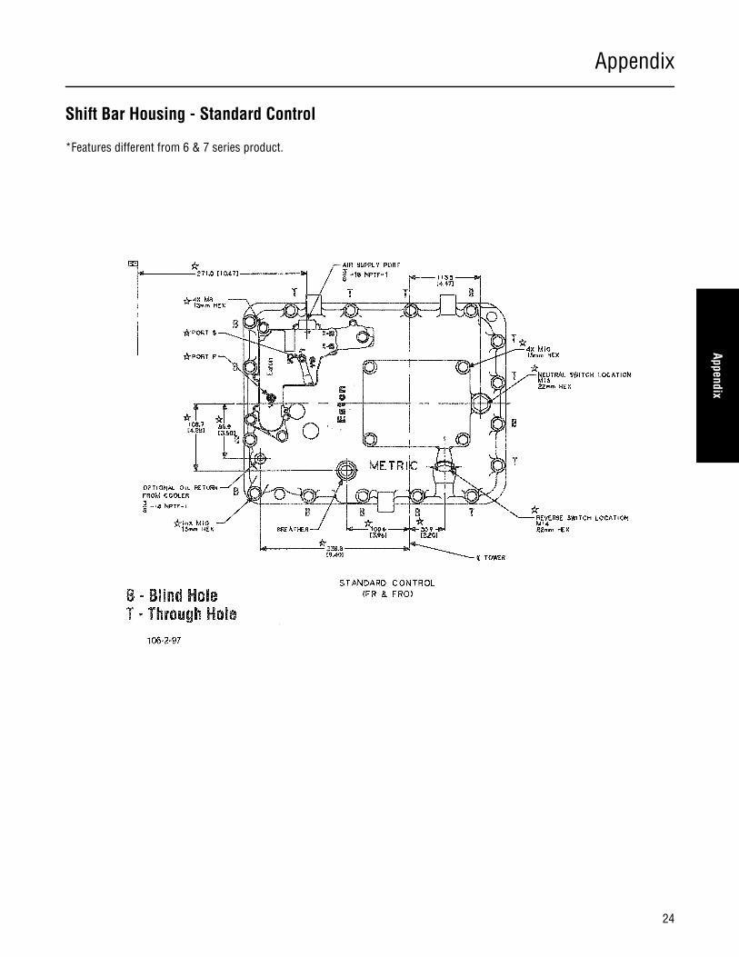
Shift Bar Housing - Standard Control
*Features different from 6 & 7 series product.

Appendix
25
Shift Bar Housing - Forward Control*Features different from 6 & 7 series product.

Appendix
26
Appendix
Reverse Switch
* Features different from 6 & 7 series product. Refer to Transmission Dimension - End View for location.
Appendix
27
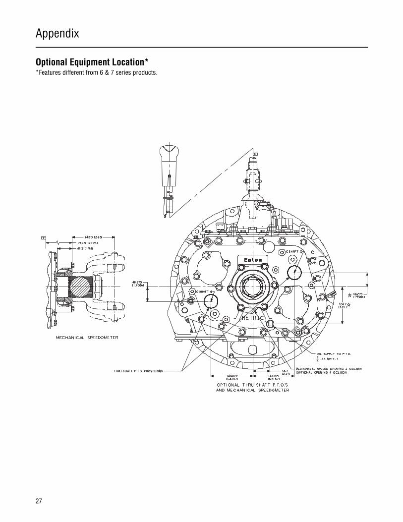
Optional Equipment Location**Features different from 6 & 7 series products.

Appendix
28
Appendix
Shift Levers
RECOMMENDED LEVER RATIO IS 5.5 - 6.5:1 LEVER RATIO = A / G**FOR SOLID LEVER SUBTRACT.02 X "A" FOR SOLID LEVER TRAVEL
Recommended Tower Types Based on Overall Height (’A’ & ’B’) andRecommend Lever Ratios (5.5 to 6.5)
Tower Type Overall Height Range (inches)
Low 30 - 35
Medium 36 - 42
High 43 - 50
LOW TOWER REDUCES HIGH TOWER SHIFT FORCE BY 35% WHEN "A" = 30"
Application (Inch) Low Med High
Travel C** .093 x A + 1.25 + (A x .02) .077 x A + 1.25 + (A x .02) .066 x A + 1.25 + (A x .02)
Travel D** .053 x A + 1.50 + (A x .02) .044 x A + 1.50 + (A x .02) .037 x A + 1.50 + (A x .02)
FRO/FRO Travel E** .273 x A + 1.25 + (A x .02) .226 x A + 1.25 + (A x .02) .193 x A + 1.25 + (A x .02)
xx2xx Travel F** .090 x A - 1.25 - (A x .02) .074 x A - 1.25 - (A x .02) .063 x A - 1.25 - (A x .02)
Family B 3.75 4.75 5.75
G 4.71 5.71 6.71

Appendix
29
Design Remedies for Shift Lever Jumpout
Annoying shift lever jumpout may occur on every truck if road conditions are severe enough, but this possibility can be minimized if some basic design guidelines are followed.
Technical Description of JumpoutShift lever jumpout is a force caused by the inertial effects of excessive road- induced vibration in the drivetrain. This road- inducedshock causes the engine/transmission to pitch on its mounts as shown in Figure 1. This pitching occurs at the natural frequencyof the engine/transmission/mount system, usually between 7 and 10 Hz. This pitching induces high vertical, fore/aft, and rotationalaccelerations on the transmission, and in particular, the shift lever. The shift lever then develops an inertial torque about its pivot,as determined by the sum of the inertial torques, as shown if Figure 2. Note that a rearward lever offset adds to the jumpouttorque, whereas a forward offset reduces the total jumpout torque.

Appendix
30
Appendix
This jumpout torque is resisted by the rail detent force times its moment arm determined by the distance between the pivot and the rail (Figure 3). When the jumpout torque overcomes the detent torque, jumpout occurs. This always occurs when the drivetrain has very low torque, such as vehicle coast conditions, since friction from torque in the drive train locks the engaged sliding clutch to the gear and greatly overcomes any jumpout forces imposed.
Since the lever itself is a dynamic system, it has its own natural frequency. Unfortunately, this also occurs between 7 and 10 Hz. This frequency is determined by lever height, lever offset, tower height, and isolator stiffness. If the natural frequency of the en-gine/transmission match that of the lever, propensity for jump out is greater because the engine amplified inertial forces are am-plified further by the lever resonance.
Steps to Prevent Shift Lever Jumpout in Truck Design
1. Design shift lever offsets forward of the shift lever pivot point. As Figure 2 shows, when the lever center of gravity is forward of the shift tower, the inertial torque due to the vertical acceleration from road-induced vibration will counteract the dominating rotational acceleration, resulting in a much lower total jumpout torque about the pivot point. Design the shift lever location slightly behind the driver to capitalize on this beneficial effect.
2. Design the engine/transmission pitch mode frequency away from the shift lever natural frequency. We recommend that the engine/transmission pitch node be designed to 10 Hz. We think this is a good trade off between noise/vibration/harsh-ness considerations and excessive engine motion. If a low shift tower is specified with an isolator, the lever system nat-ural frequency will occur at 8 Hz or below. This is far enough away from the engine/transmission pitch mode frequency to eliminate any coincident amplification.
3. Provide friction damping in the rear transmission support. Double leaf springs at the transmission rear support can pro-vide interleaf friction that will effectively damp the engine/transmission pitch mode motion, thereby reducing jumpout torques.
Note: Shift lever mechanical advantage guidelines are as follows: FS Transmission Models - 8.5/1 to 10.0/1, T, RT, FR, FRO Trans-mission Models - 5.5/1 to 6.5/1.

Appendix
31
Optional Internal Cooler - Side View

Appendix
32
Appendix
Optional Internal Cooler - End View
222.50 [8.760]
271.53 [10.690]
50.80 [2.000]
4.32 [.170]
17.02 [.670]
22.0
79.0 [3.11]
Thermocouple & Drain.500 - 14 NPTF - 1 (Standard).750 - 16 UNF (Optional)

Appendix
33
Optional Internal Cooler - Bottom View
168.50 [6.634]
47.37 [1.865]75.13 [2.958]
287.91 [11.335]Front Face of Case
1.062 - 12 UN Fill Plug with Internal 12.7 [.50] Square Drive
1.062 - 12 UN Drain Plug with Internal 12.7 [.50] Square Drive
Thermocouple Location.500 - 14 NPTF - 1
(Standard) 2X .500 - 14 NPTF Inlet or Outlet(Optional) 2X .750 - 16 UNF Inlet or Outlet


Eaton Corporation1111 Superior Ave.Cleveland, OH 44114
Copyright Eaton Corporation, 2012. Eaton hereby grant their customers, vendors, or distributors permission to freely copy, reproduce and/or distribute this document in printed format. It may be copied only in its entirety without any changes or modifications. THIS INFORMATION IS NOT INTENDED FOR SALE OR RESALE, AND THIS NOTICE MUST REMAIN ON ALL COPIES.
Note: Features and specifications listed in this document are subject to change without notice and represent the maximum capabilities of the software and products with all options installed. Although every attempt has been made to ensure the accuracy of information contained within, Eaton makes no representation about the completeness, correctness or accuracy and assumes no responsibility for any errors or omissions. Features and functionality may vary depending on selected options.
For spec’ing or service assistance, call 1-800-826-HELP (4357) or visit our web site at:
www.roadranger.com. In Mexico, call 001-800-826-4357.