easygen1000 series user manual
TRANSCRIPT

37181
Operation Software Version 1.0xxx
Manual 37181
easYgen-1000 Genset Control

Manual 37181 easYgen-1000 - Genset Control
Page 2/35 © Woodward
WARNING Read this entire manual and all other publications pertaining to the work to be performed before install-ing, operating, or servicing this equipment. Practice all plant and safety instructions and precautions. Failure to follow instructions can cause personal injury and/or property damage. The engine, turbine, or other type of prime mover should be equipped with an overspeed (overtempera-ture, or overpressure, where applicable) shutdown device(s), that operates totally independently of the prime mover control device(s) to protect against runaway or damage to the engine, turbine, or other type of prime mover with possible personal injury or loss of life should the mechanical-hydraulic gov-ernor(s) or electric control(s), the actuator(s), fuel control(s), the driving mechanism(s), the linkage(s), or the controlled device(s) fail.
CAUTION To prevent damage to a control system that uses an alternator or battery-charging device, make sure the charging device is turned off before disconnecting the battery from the system. Electronic controls contain static-sensitive parts. Observe the following precautions to prevent dam-age to these parts. • Discharge body static before handling the control (with power to the control turned off, contact a
grounded surface and maintain contact while handling the control). • Avoid all plastic, vinyl, and Styrofoam (except antistatic versions) around printed circuit boards. • Do not touch the components or conductors on a printed circuit board with your hands or with
conductive devices. Important definitions
WARNING Indicates a potentially hazardous situation that, if not avoided, could result in death or serious injury.
CAUTION indicates a potentially hazardous situation that, if not avoided, could result in damage to equipment.
NOTE Provides other helpful information that does not fall under the warning or caution categories.
Woodward Governor Company reserves the right to update any portion of this publication at any time. Information provided by Wood-ward Governor Company is believed to be correct and reliable. However, no responsibility is assumed by Woodward Governor Company unless otherwise expressly undertaken.
© Woodward Governor Company
All Rights Reserved.

Manual 37181 easYgen-1000 - Genset Control
© Woodward Page 3/35
Content
CHAPTER 1. GENERAL INFORMATION.........................................................................................5 Linked documents ...................................................................................................................................5 Short description .....................................................................................................................................6 CHAPTER 2. NAVIGATION / OPERATION......................................................................................9 Navigation .............................................................................................................................................10 Operation ..............................................................................................................................................16
Display ........................................................................................................................................17 Mode ...........................................................................................................................................18 Operation ....................................................................................................................................19 Navigation ...................................................................................................................................20
CHAPTER 3. FUNCTIONAL DESCRIPTION ..................................................................................21 Overview ...............................................................................................................................................21 Application modes.................................................................................................................................22
Application mode {BM} - Basic Mode .........................................................................................22 Application mode {1o} – 0 CB mode...........................................................................................22 Application mode {1oc} – 1 CB mode.........................................................................................22 Application mode {2oc} – 2 CB mode.........................................................................................22
Operating modes...................................................................................................................................23 Operating mode STOP ...............................................................................................................23 Operating mode MANUAL..........................................................................................................24 Operating mode AUTOMATIC....................................................................................................25
CHAPTER 4. CONFIGURATION ..................................................................................................27 Structure of the parameters ..................................................................................................................27 Parameters............................................................................................................................................29
Language ....................................................................................................................................29 Password ....................................................................................................................................29 Display contrast ..........................................................................................................................30 Acknowledgement of centralized alarm......................................................................................30 Real-time clock - time .................................................................................................................30 Real-time clock - date .................................................................................................................31 Code levels .................................................................................................................................31 Password ....................................................................................................................................32 Factory (default) values ..............................................................................................................32
APPENDIX A. MESSAGES.........................................................................................................33 Status messages...................................................................................................................................33 Alarm messages ...................................................................................................................................34

Manual 37181 easYgen-1000 - Genset Control
Page 4/35 © Woodward
Illustrations and Tables
Illustrations Figure 1-2: Functional overview................................................................................................................................................ 6 Figure 2-1: Front panel and display ........................................................................................................................................... 9 Figure 2-2: Screens and Menus - Overview............................................................................................................................. 10 Figure 2-3: Screen - Level overview........................................................................................................................................ 16 Figure 4-1: Configuration screens (overview) ......................................................................................................................... 27
Tables Table 1-1: Manual - Overview................................................................................................................................................... 5 Table 2-4: Display - Measuring values .................................................................................................................................... 17 Table 3-1: Functional description - Overview ......................................................................................................................... 21 Table 3-2: Functional description - AMF conditions............................................................................................................... 26

Manual 37181 easYgen-1000 - Genset Control
© Woodward Page 5/35
Chapter 1. General Information
Linked documents Type English German easYgen-1000 Series easYgen-1000 - Installation 37203 GR37203 easYgen-1000 - Configuration 37204 GR37204 easYgen-1000 - Operation this manual 37181 GR37181 easYgen-1000 - Application 37205 GR37205 easYgen-1000 - Interface 37262 GR37262 Additional Manuals IKD 1 - Manual 37135 GR37135 Discrete expansion board with 8 discrete inputs and 8 relay outputs that can be coupled via the CAN bus to the control unit. Evalua-
tion of the discrete inputs as well as control of the relay outputs is done via the control unit. IKN 1 - Manual 37136 GR37136 20channel NiCrNi temperature scanner that monitors the temperature values for exceeding or falling below a threshold value, meas-
ured through senders on the IKN 1. A configured relay on the board of the IKN 1 will trip. The IKN 1 can be coupled with the con-trol unit using the CAN bus to display measuring values as well as alarms.
LeoPC - Manual 37146 GR37146 PC program for visualization, for configuration, for remote control, for data logging, for language upload, for alarm and user man-
agement and for management of the event recorder. This manual describes the use of the program. LeoPC - Manual 37164 GR37164 PC program for visualization, for configuration, for remote control, for data logging, for language upload, for alarm and user man-
agement and for management of the event recorder. This manual describes the programming of the program. GW 4 - Manual 37133 GR37133 Gateway for transferring the CAN bus to any other interface or bus.
ST 3 - Manual 37112 GR37112 Control to govern the air fuel ratio of a gas engine. The ratio will be directly measured though a Lambda probe and controlled to a
configured value.
Table 1-1: Manual - Overview

Manual 37181 easYgen-1000 - Genset Control
Page 6/35 © Woodward
Short description
{2oc}{1oc}{1o}
GGGGalt.
alt.
{BM}
© Woodward
OpenClose
4 Configurable Modes- Base Mode - 1 CB Mode - 1 CB Mode - 2 CB Mode
Graphical interactiveLC display with soft-keys for multiple applications
Protection
(no CB operation)(GCB )(GCP /(GCB/MCB / )
(128x64 pixel)
- Over-/underspeed- Over-/undervoltage/-frequency - Overload/load imbalance - Reverse/reduced power- Definite/inverse-time overcurrent - Ground fault
openopen
openclose
close)
FlexAppTM
FlexRangeTM
DynamicsLCDTM
FlexCANTM (32 partizipants)
Measuring voltage- Rated 120 Vac (max. 150 Vac) - Rated 480 Vac (max. 600 Vac)- True RMS
Measuring current- Rated ../5 A or ../1 A- True RMS- 3 inputs for generator current- 1 input alternatively used as mains or ground current
and
LogicsManagerTM
FlexInTM
Start/Stop for Diesel/Gas Engines
VDO, resistive, 0/4..20 mA
AMF/single unit/stand-by operationATS/open transition/break-before-make logicMulti lingual capability (Asia characters)Event recorder (50 events) with real time clockUL/cUL Listed
GL, LR, other upon requestCE MarkedMarine Approval:
Pickup (inductive/switching)
MC
B
OpenClose
Load
GC
B
GC
B
GC
B
OpenCloseOpen
Figure 1-2: Functional overview

Manual 37181 easYgen-1000 - Genset Control
© Woodward Page 7/35
The easYgen-1000 Series generator set controllers provide the following functions:
• Gen-set control • Engine and generator protection • Engine data measurement -
o including oil pressure and temperature, coolant temperature, battery voltage, speed, service hours, etc.
• Generator data measurement - o including voltage, current, power, kvar, kW, kWh, etc.
• Engine crank sequencing • Alarm display with circuit breaker trip and engine shutdown • AMF (automatic mains failure) standby genset control, with automatic engine start on a mains failure
detection, with open transition breaker control • CAN bus communications to engine controllers and plant management systems
Type designation is as follows: easYgen -xxxx- 5 5 -h0018 B/ -ABDEF..Z
Options according to list of options. These options can be found in the manual. Each chapter headline points out if the described function is standard or has to be or-dered optional.
Mounting [B]..Flush-mounting [M].. DIN-rail/rear panel mounting
Hardware variation
very special types; e. g. other relays
CT's, current transformers, secondary [1] = ../1 A [5] = ../5 A
PT's, maximum voltage transformers, secondary [1] = 100 Vac [4] = 400 Vac [5] = 480 Vac [7] = 690 Vac
Model [-1000] = Series [-1100] = Model '1100" [-1200] = Model '1200" [-1400] = Model '1400" [-1500] = Model '1500"
Type Examples: EASYGEN-1500-55B (standard unit, 120 & 480 Vac inputs, ../5 A measuring inputs, flush-mounting) EASYGEN-1500-51B (standard unit, 120 & 480 Vac inputs,. ../1 A measuring inputs, flush-mounting) EASYGEN-1400-55M (standard unit, 120 & 480 Vac inputs, ../5 A measuring inputs, DIN-rail mounting) EASYGEN-1400-51M (standard unit, 120 & 480 Vac inputs,. ../1 A measuring inputs, DIN-rail mounting )

Manual 37181 easYgen-1000 - Genset Control
Page 8/35 © Woodward
Intended Use The unit must only be operated according to the guidelines described in this manual. The prerequi-site for a proper and safe operation of the product is correct transportation, storage, and installation as well as careful operation and maintenance.
NOTE This manual has been developed for an unit fitted with all available options. Inputs/outputs, functions, configuration screens and other details described, which do not exist on your unit may be ignored. The present manual has been prepared to enable the installation and commissioning of the unit. On account of the large variety of parameter settings, it is not possible to cover every possible combina-tion. The manual is therefore only a guide. In case of incorrect entries or a total loss of functions, the default settings can be taken from the enclosed list of parameters.

Manual 37181 easYgen-1000 - Genset Control
© Woodward Page 9/35
Chapter 2. Navigation / Operation
easYgen-1000 "BLUE" easYgen-1000 "RED"
Figure 2-1: Front panel and display
Figure 2-1 illustrates the front panel/display which includes push buttons, LED's and the LC display. A short de-scription of the front panel is given below. NOTE
This push button is ALWAYS active and will stop the engine when pressed.
Function blocks
Buttons that have the same function within one screen are grouped into function blocks. The function blocks are defined as: Display......... Change the method of voltage and power calculations displayed (page 16). Mode............ Change the mode of operation (page 18). Operation .... Used to perform manual operation of the genset (page 19). Navigation... Navigation between system and configuration screens, and alarm list (page 19).
1 2 3 4 5 6 7 8 9 10 11
Push buttons
The push buttons on the front panel are assigned to softkeys on the display. Each softkey is as-signed to a function depending on the mode of operation.
20 LC display
The display contains softkeys, measuring values, modes of operation and alarms. The structure of the screens as well as the description are detailed in the "Navigation" chapter (page 10).
21 22 LED
The left LED indicates that the unit is in STOP mode. The right LED indicates that alarm mes-sages are present in the unit.

Manual 37181 easYgen-1000 - Genset Control
Page 10/35 © Woodward
Navigation Figure 2-2 illustrates an overview for the navigation via the display. This demonstration will help the user through the menus and screens of the easYgen. The following and previous screens are marked in Yellow, the active screen is marked in Red. If submenus are present they are marked in Grey.
O verview(Generator)
ParameterList 1
ParameterList 2
ParameterList 3
ParameterList n
Parameter 1
1 1 1 1 1 1 1
1 1 1 1 1 1 1 1 11 1 1 1 1 1 1 1 11 1 1 1 1 1 1 1 1
1 1 1 1 1 1 11 1 1 1 1 11 1 1 1 1
1 1 1 11 1 1 1 1
1 1 1 1 1 11 1 1 1 1 1 11 1 1 1 1 1 1 1 1
1 1 1 1 1 1 1 1 11 1 1 1 1 1 1 1 1
1 1 1 1 1 1 1
Alarm List
Details(Generator)
O verview(Mains)
Details(Mains)
O verview(AI)
O verview(DI/DO )
TimeDate
Parameter 2
Parameter 3
Parameter 4
Bereich
Bereich
Bereich
Bereich
Parameter 1
Parameter 2
Parameter 3
Parameter 4
Bereich
Bereich
Bereich
Bereich
Parameter 1
Parameter 2
Parameter 3
Parameter 4
Bereich
Bereich
Bereich
Bereich
Parameter 1
Parameter 2
Parameter 3
Parameter 4
Bereich
Bereich
Bereich
Bereich
1 1 1 1 1 1 1
1 1 1 1 1 1 1 1 11 1 1 1 1 1 1 1 11 1 1 1 1 1 1 1 1
1 1 1 1 1 1 11 1 1 1 1 11 1 1 1 1
1 1 1 11 1 1 1 1
1 1 1 1 1 11 1 1 1 1 1 11 1 1 1 1 1 1 1 1
1 1 1 1 1 1 1 1 11 1 1 1 1 1 1 1 1
1 1 1 1 1 1 1
Screen 2
Screen 1
Screen 3
Screen 4
Screen 5
Screen 6
Screen 7
Figure 2-2: Screens and Menus - Overview

Manual 37181 easYgen-1000 - Genset Control
© Woodward Page 11/35
Screen "Generator values - overview" / "Starting screen" [all application modes]
This screen appears upon startup of the unit. The generator symbol ( ) in-dicates that generator values are displayed.
Navigate to the next screen. Display the parameters.
Switch the display of the generator voltages (between star and wye voltages). Display the alarm messages (of the event recorder).
Operating mode MANUAL: start/stop engine. Operating mode MANUAL: GCB(/MCB) open/close.
Change into operating mode AUTOMATIC. Change into operating mode MANUAL.
1 1 1 1 1 1 11 1 1 1 1 1 1 1 11 1 1 1 1 1 1 1 11 1 1 1 1 1 1 1 11 1 1 1 1 1 1 1 11 11 1 1 1 1 1 1 1 11 11 1 1 11 1 1 1 1 11 1 1 1 1 1 1 11 1 1 1 1 1 1 1 11 1 1 1 1 1 1 1 11 1 1 1 1 1 1 1 1
1 1 1 1 1 1 1
1 1 1 1 1 1 1
1 1 1 1 1 1 1 1 11 1 1 1 1 1 1 1 11 1 1 1 1 1 1 1 11 1 1 1 1 1 11 1 1 1 1 11 1 1 1 1
1 1 1 11 1 1 1 1
1 1 1 1 1 11 1 1 1 1 1 11 1 1 1 1 1 1 1 11 1 1 1 1 1 1 1 11 1 1 1 1 1 1 1 1
1 1 1 1 1 1 1
1 1 1 1 1 1 11 1 1 1 1 1 1 11 1 1 1 1 11 1 1 11 1 1 11 1 1 11 1 1 11 1 1 11 1 1 11 1 1 1 1 11 1 1 1 1 1 1 11 1 1 1 1 1 1 11 1 1 1 1 1 1 1 11 1 1 1 1 1 1 1
1 1 1 1 1 1 1
Change into operating mode STOP.
Screen "Mains values - overview" [only application mode {2oc}]
This screen appears after pressing the softkey once. The mains symbol ( ) indicates that the mains measuring values are displayed.
Navigate to the next screen. Navigate to the previous screen.
Switch the display of the mains voltages (between star and delta voltages). Display the alarm messages (of the event recorder).
Operating mode MAN: start/stop engine. Operating mode MAN: GCB(/MCB) open/closed.
Change into operating mode AUTOMATIC Change into operating mode MAN.
1 1 1 1 1 1 1
1 1 1 1 1 1 1 1 11 1 1 1 1 1 1 1 11 1 1 1 1 1 1 1 11 1 1 1 1 1 11 1 1 1 1 11 1 1 1 1
1 1 1 11 1 1 1 11 1 1 1 1 11 1 1 1 1 1 11 1 1 1 1 1 1 1 11 1 1 1 1 1 1 1 11 1 1 1 1 1 1 1 1
1 1 1 1 1 1 1
1 1 1 1 1 1 11 1 1 1 1 1 1 11 1 1 1 1 11 1 1 11 1 1 11 1 1 11 1 1 1
1 1 1 11 1 1 11 1 1 1 1 11 1 1 1 1 1 1 11 1 1 1 1 1 1 11 1 1 1 1 1 1 1 11 1 1 1 1 1 1 1
1 1 1 1 1 1 1
1 1 1 1 1 1 11 1 1 1 1 1 1 1 11 1 1 1 1 1 1 1 11 1 1 1 1 1 1 1 11 1 1 1 1 1 1 1 11 11 1 1 1 1 1 1 1 11 11 1 1 11 1 1 1 1 11 1 1 1 1 1 1 11 1 1 1 1 1 1 1 11 1 1 1 1 1 1 1 11 1 1 1 1 1 1 1 1
1 1 1 1 1 1 1
Change into operating mode STOP.

Manual 37181 easYgen-1000 - Genset Control
Page 12/35 © Woodward
Screen "Generator values - Details" [all application modes]
This screen appears after pressing the softkey again. Here all measured values of the generator are displayed in one screen.
Navigate to the next screen.
Navigate to the previous screen.
Jump to the start screen.
Change into operating mode STOP.
1 1 1 1 1 1 11 1 1 1 1 1 1 1 11 1 1 1 1 1 1 1 11 1 1 1 1 1 1 1 11 1 1 1 1 1 1 1 11 11 1 1 1 1 1 1 1 11 11 1 1 11 1 1 1 1 11 1 1 1 1 1 1 11 1 1 1 1 1 1 1 11 1 1 1 1 1 1 1 11 1 1 1 1 1 1 1 1
1 1 1 1 1 1 1
1 / 2 / 3..........Generator voltages VL1N / VL2N / VL3N and
generator currents IL1 / IL2 / IL3 12 / 23 / 31....Gnerator voltages VL12 / VL23 / VL31 00.00Hz ........Generator frequency 000kW..........Generator real power 000kvar ........Generator reactive power 0.00 ...............Generator power factor
Screen "Mains values - Details" [only application mode {2oc}]
This screen appears after pressing the softkey again. Here all measured values of the mains are displayed in one screen.
Navigate to the next screen.
Navigate to the previous screen.
Jump to the start screen.
Change into operating mode STOP.
1 1 1 1 1 1 11 1 1 1 1 1 1 1 11 1 1 1 1 1 1 1 11 1 1 1 1 1 1 1 11 1 1 1 1 1 1 1 11 1
1 1 1 1 1 1 1 1 11 11 1 1 11 1 1 1 1 1
1 1 1 1 1 1 1 11 1 1 1 1 1 1 1 11 1 1 1 1 1 1 1 11 1 1 1 1 1 1 1 1
1 1 1 1 1 1 1
1 / 2 / 3..........Mains voltages VL1N / VL2N / VL3N and
mains current IL 12 / 23 / 31....Mains voltages VL12 / VL23 / VL31 00.00Hz ........Mains frequency 000kW..........Mains real power 000kvar ........Mains reactive power 0.00 ...............Mains power factor

Manual 37181 easYgen-1000 - Genset Control
© Woodward Page 13/35
Screen "Slave pointer current" [all operating modes]
This screen appears after pressing the softkey again. Here the slave pointers (maximum currents) are displayed.
Navigate to the next screen. Navigate to the previous screen.
Jump to the start screen.
Left of the sign: Current value Right of the sign: Maximum values (slave pointer) Change to configuration menu and reset the maximum values.
Change into operating mode STOP.
1 1 1 1 1 1 11 1 1 1 1 1 1 1 11 1 1 1 1 1 1 1 11 1 1 1 1 1 1 1 11 1 1 1 1 1 1 1 11 11 1 1 1 1 1 1 1 11 11 1 1 11 1 1 1 1 11 1 1 1 1 1 1 11 1 1 1 1 1 1 1 11 1 1 1 1 1 1 1 11 1 1 1 1 1 1 1 1
1 1 1 1 1 1 1
1 / 2 / 3 ......... Generator current IL1 / IL2 / IL3 and
mains current IL
Screen "Analog values - Details" [all operating modes]
This screen appears after pressing the softkey again. Here all analog measured values are displayed graphically and numerically.
Navigate to the next screen. Navigate to the previous screen.
Jump to the start screen.
Change into operating mode STOP.
1 1 1 1 1 1 11 1 1 1 1 1 1 1 11 1 1 1 1 1 1 1 11 1 1 1 1 1 1 1 11 1 1 1 1 1 1 1 11 11 1 1 1 1 1 1 1 11 11 1 1 11 1 1 1 1 11 1 1 1 1 1 1 11 1 1 1 1 1 1 1 11 1 1 1 1 1 1 1 11 1 1 1 1 1 1 1 1
1 1 1 1 1 1 1

Manual 37181 easYgen-1000 - Genset Control
Page 14/35 © Woodward
Screen "Discrete inputs / relay outputs – Status display" [all application modes]
This screen appears after pressing the softkey again. Discrete input and relay output status are displayed.
Navigate to the next screen.
Navigate to the previous screen.
Jump to the start screen.
Change into operating mode STOP.
Status display of the discrete inputs and relay outputs. (Note: Whether a discrete input or a relay output is currently physically closed or not, depends on the adjusted logic "NO/NC". This screen gives information whether the inputs/outputs are logi-cally controlled.
The discrete input/the relay output is not set.
The discrete input/the relay output is set.
1 1 1 1 1 1 11 1 1 1 1 1 1 1 11 1 1 1 1 1 1 1 11 1 1 1 1 1 1 1 11 1 1 1 1 1 1 1 11 11 1 1 1 1 1 1 1 11 11 1 1 11 1 1 1 1 11 1 1 1 1 1 1 11 1 1 1 1 1 1 1 11 1 1 1 1 1 1 1 11 1 1 1 1 1 1 1 1
1 1 1 1 1 1 1
Screen "Time / Date" [all operating modes]
This screen appears after pressing the softkey once more. Here the time and date are displayed.
Navigate to the next screen
Navigate to the previous screen.
Jump to the start screen.
Change into operating mode STOP.
1 1 1 1 1 1 11 1 1 1 1 1 1 1 11 1 1 1 1 1 1 1 11 1 1 1 1 1 1 1 11 1 1 1 1 1 1 1 11 11 1 1 1 1 1 1 1 11 11 1 1 11 1 1 1 1 11 1 1 1 1 1 1 11 1 1 1 1 1 1 1 11 1 1 1 1 1 1 1 11 1 1 1 1 1 1 1 1
1 1 1 1 1 1 1
0000-XXX-00 - Date
0000 = Year XXX = Month 00 = Day
00:00:00 - Time 00 = Hour 00 = Minute 00 = Second

Manual 37181 easYgen-1000 - Genset Control
© Woodward Page 15/35
Screen "Counters" [all operating modes]
This screen appears after pressing the softkey once more. Here the counters are displayed.
Navigate to the next screen Navigate to the previous screen.
Jump to the start screen.
Change into operating mode STOP.
1 1 1 1 1 1 11 1 1 1 1 1 1 1 11 1 1 1 1 1 1 1 11 1 1 1 1 1 1 1 11 1 1 1 1 1 1 1 11 11 1 1 1 1 1 1 1 11 11 1 1 11 1 1 1 1 11 1 1 1 1 1 1 11 1 1 1 1 1 1 1 11 1 1 1 1 1 1 1 11 1 1 1 1 1 1 1 1
1 1 1 1 1 1 1
Hours of operation 00 h - Operating hours counter 00h = Total operating hours (hours in operation)
Number of starts 00 - Start counter 00 = Total number of starts
Energy 0.00 kWh - Generator real energy 0.00MWh = Total generator real energy
Pos. reactive energy 0.00 Mvar - Generator reactive energy 0.00Mvarh = Total generator reactive energy
Screen "Maintenance in ..." [all operating modes]
This screen appears after pressing the softkey once more. Here the re-maining days/hours to the next maintenance call are displayed.
Navigate to the previous screen.
Jump to the start screen.
Change to configuration menu and reset the maximum values.
Change into operating mode STOP.
1 1 1 1 1 1 11 1 1 1 1 1 1 1 11 1 1 1 1 1 1 1 11 1 1 1 1 1 1 1 11 1 1 1 1 1 1 1 11 11 1 1 1 1 1 1 1 11 11 1 1 11 1 1 1 1 11 1 1 1 1 1 1 11 1 1 1 1 1 1 1 11 1 1 1 1 1 1 1 11 1 1 1 1 1 1 1 1
1 1 1 1 1 1 1
Days until mainten. 000d - Remaining maintenance days 000d = Once this days (plus the remaining mainte-nacnce hours) are exceeded the control will output an alarm message to maintain the genset. With fin-ishing the maintenance the maintenance counters have to be reset.
Hours until maintenc. 000h - Remaining maintenance hours 000h = Once this hours (plus the remaining main-tenacnce hours) are exceeded the control will out-put an alarm message to maintain the genset. With finishing the maintenance the maintenance counters have to be reset.

Manual 37181 easYgen-1000 - Genset Control
Page 16/35 © Woodward
Operation To illustrate values the display is partitioned into different levels which give a concentrated overview of all data.
Figure 2-3: Screen - Level overview
"Values"
The "values" screen illustrates all power related information includ-ing voltages, frequencies, and power values.
"Messages"
The "message" screen shows all active alarms and operations infor-mation.
"Operation"
The "operation" screen illustrates a one line diagram of the system application showing current status of the engine and power circuit breakers. This level is also used for manual operation of the genset.
"Softkeys"
The softkeys permit navigation between screens, levels and func-tions.

Manual 37181 easYgen-1000 - Genset Control
© Woodward Page 17/35
Display
Softkey "Voltage display"
The voltage display softkey changes the type of power calcu-lations displayed, line-line or line-neutral. The amount of in-formation available from the system depends on the measur-ing type configured in the control. Table 2-4 illustrates what values are available depending on the configured measure-ment type.
Selection of meas. point
Measuring point Scroll display Symbol of' the displayed voltage
Displayed at parameter setting
Delta Wye
0× Generator
0× (6×)
Delta L1-L2 yes yes
1×
Delta L2-L3 yes yes
2×
Delta L3-L1 yes yes
3×
Wye L1-N --- yes
4×
Wye L2-N --- yes
L1
L2
N
L3 3~G
V Gen
L1-
N
V L
2-N
Gen
V Gen
L3-
N
V Gen
L1-
L2
V Gen
L2-
L3
V Gen
L3-
L1
5×
Wye L3-N --- yes
1× Mains
0× (6×)
Delta L1-L2 yes yes
1×
Delta L2-L3 yes yes
2×
Delta L3-L1 yes yes
3×
Wye L1-N --- yes
4×
Wye L2-N --- yes
L1
L2
N
L3
V Mai
ns L
1-N
V L
2-N
Mai
ns
V L
3-N
Mai
ns
V L
1-L2
Mai
ns
V L
2-L3
Mai
ns
V Mai
ns L
3-L1
5×
Wye L3-N --- yes
Table 2-4: Display - Measuring values

Manual 37181 easYgen-1000 - Genset Control
Page 18/35 © Woodward
Mode
Softkeys "Mode"
By pressing the push buttons , or the operating mode is selected. Corresponding to the selected application mode different softkeys are activated or deactivated on the display. Furthermore in a engine symbol the selected operat-ing mode is displayed. If the operation mode STOP is selected the LED right beside the push button flashes.
Operating mode STOP
When STOP is selected, the engine is stopped.
Operating mode AUTOMATIC
When AUTOMATIC is selected all engine start/stop functionality and circuit breaker
Operating mode MANUAL
When MANUAL is selected, all engine and breaker control is performed manually via softkeys.

Manual 37181 easYgen-1000 - Genset Control
© Woodward Page 19/35
Operation
Softkeys "Mode"
If the unit is in operating mode MANUAL the softkeys are ac-tivated for manual operation of the engine and the power cir-cuit breakers. The symbols "0" and "I" indicate additional ac-tions that are processed at the moment.
Engine Start/Stop
Starting process: By pressing this push button the engine is started. • Successful: If the starting process was successful, the arrow turns within this softkey
and the "I" within this softkey lights up. • Unsuccessful: If the starting process was not successful, the "I" will flash. Stop process: Pressing the softkey again will stop the engine. • Successful: If the stop process was successful, the "0" is displayed solidly and the ro-
tating arrow disappears. • Unsuccessful: If the engine cannot be stopped, the arrow continues to turn and the "0"
flashes.
Power circuit breaker open/close (GCB/MCB)
Close: By pressing this push button the circuit breaker is closed. • Successful: If the closing process was successful, the breaker symbol rotates horizontal
and the "I" lights within this softkey. • Unsuccessful: If the closing process was not successful, the breaker symbol remains
vertical and the "I" will flash. Open: To open this breaker this softkey is pressed as well. • Successful: If the opening process was successful, the "0" is lit and the breaker symbol
rotates vertical. • Unsuccessful: If the breaker cannot be opened, the breaker symbol remains horizontal
and the "0" flashes.
Manual 37181 easYgen-1000 - Genset Control
Page 20/35 © Woodward
Navigation
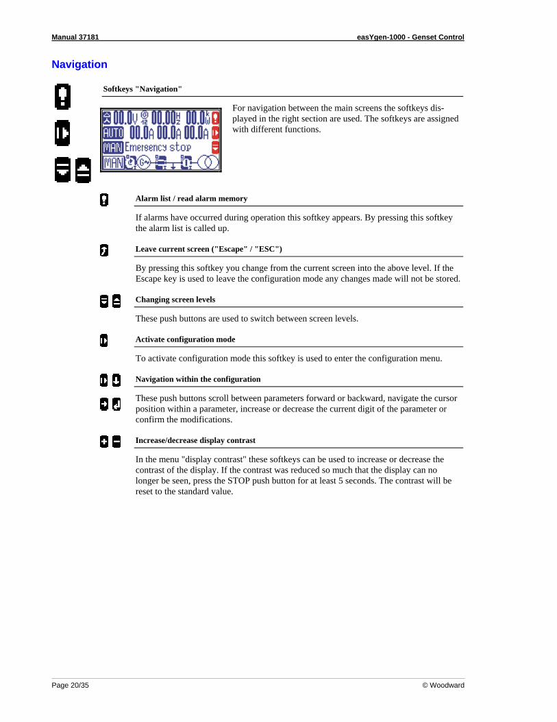
Softkeys "Navigation"
For navigation between the main screens the softkeys dis-played in the right section are used. The softkeys are assigned with different functions.
Alarm list / read alarm memory
If alarms have occurred during operation this softkey appears. By pressing this softkey the alarm list is called up.
Leave current screen ("Escape" / "ESC")
By pressing this softkey you change from the current screen into the above level. If the Escape key is used to leave the configuration mode any changes made will not be stored.
Changing screen levels
These push buttons are used to switch between screen levels.
Activate configuration mode
To activate configuration mode this softkey is used to enter the configuration menu.
Navigation within the configuration
These push buttons scroll between parameters forward or backward, navigate the cursor position within a parameter, increase or decrease the current digit of the parameter or confirm the modifications.
Increase/decrease display contrast
In the menu "display contrast" these softkeys can be used to increase or decrease the contrast of the display. If the contrast was reduced so much that the display can no longer be seen, press the STOP push button for at least 5 seconds. The contrast will be reset to the standard value.

Manual 37181 easYgen-1000 - Genset Control
© Woodward Page 21/35
Chapter 3. Functional Description
Overview Applicatio1n Mode {BM} {1o} {1oc} {2oc} Operation Mode MAN AUTO MAN AUTO MAN AUTO MAN AUTO Operate the engine • Start engine by ... ... the push buttons (Softkeys) YES --- YES --- YES --- YES --- ... the discrete inputs --- YES --- YES --- YES --- YES ... the automatic (emergency power) --- --- --- --- --- --- --- YES ... the CAN bus --- YES --- YES --- YES --- YES • Stop engine by ... ... the push buttons (STOP push button) YES YES YES YES YES YES YES YES ... the push buttons (Softkeys) YES --- YES --- YES --- YES --- ... the discrete inputs --- YES --- YES --- YES --- YES ... the automatic (emergency power) --- --- --- --- --- --- --- YES ... the CAN bus --- YES --- YES --- YES --- YES ... an alarm YES YES YES YES YES YES YES YES Operate GCB • close GCB ... the push buttons (Softkeys) --- --- --- --- YES --- YES --- ... the discrete inputs --- --- --- --- --- YES --- YES ... the automatic (emergency power) --- --- --- --- --- --- --- YES ... the CAN bus --- --- --- --- --- YES --- YES ... an alarm (e.g. MCB failure) --- --- --- --- --- --- --- YES • open GCB ... the push buttons (STOP push button) YES YES YES YES YES YES YES YES ... the push buttons (Softkeys) --- --- YES --- YES --- YES --- ... the discrete inputs --- --- --- YES --- YES --- YES ... the automatic (emergency power) --- --- --- --- --- --- --- YES ... the CAN bus --- --- --- YES --- YES --- YES ... an alarm --- --- YES YES YES YES YES YES Operate MCB • open MCB ... the push buttons (Softkeys) --- --- --- --- --- --- YES --- ... the discrete inputs --- --- --- --- --- --- --- YES ... the automatic (emergency power) --- --- --- --- --- --- --- YES ... the CAN bus --- --- --- --- --- --- --- YES ... an alarm --- --- --- --- --- --- YES YES • close MCB ... the push buttons (Softkeys) --- --- --- --- --- --- YES --- ... the discrete inputs --- --- --- --- --- --- --- YES ... the automatic (emergency power) --- --- --- --- --- --- --- YES ... the CAN bus --- --- --- --- --- --- --- YES ... an alarm --- --- --- --- --- --- --- YES
Table 3-1: Functional description - Overview
• Application Mode (page 22): depends on the application; defines the number/function of the breakers ({BM}, {1o}, {1oc}, {2oc}). • Operating Mode (page 23): depends on the application; separates between STOP, MANUAL and AUTOMATIC.

Manual 37181 easYgen-1000 - Genset Control
Page 22/35 © Woodward
Application modes The application mode can be changed only during configuration with the correct passwords. The most important features of the four application modes are illustrated in the following chapters. The exact description of the func-tions that are possible during each application mode can be found in the configuration manual (manual 37204). Table 3-1: Functional description - Overview describes which function is available in each application mode.
Application mode {BM} - Basic Mode
3
3
G 1
S/S
This application mode provides the following functions: • the operation of the engine (start/stop) and/or • the measuring and display of values.
Application mode {1o} – 0 CB mode
GCB3
3
G 1
S/S
open
Additionally to the application mode {BM} the following functions are possible: • monitoring of selected values and protection of the generator and the engine as well as • opening the GCB.
Application mode {1oc} – 1 CB mode
GCB3
3
G 1
S/S
open
/clo
se
Additionally to the application mode {1o} the following functions are possible: • closing the GCB and • deadbus test logic.
Application mode {2oc} – 2 CB mode
3
1
MCB
GCB3
3
G 1
S/S
open
/clo
se
Additionally to the application mode {1oc} the following functions are possible: • operating the MCB (open/close) and • emergency power (AMF automatic mains failure) operation.

Manual 37181 easYgen-1000 - Genset Control
© Woodward Page 23/35
Operating modes
Operating mode STOP NOTE
Selecting the operating mode STOP is not the same as an EMERGENCY STOP. In some cases the easYgen will perform additional logic before the engine is stopped. An EMERGENCY STOP discrete in-put can and should be programmed as a class F alarm.
In the operating mode STOP neither the engine nor any switch can be operated. Dependent on the application mode the engine and the power circuit breakers can not be operated. If the operating mode STOP has been selected while
the engine was already stopped • the GCB will not be closed. • The fuel solid relay will not be closed. • The discrete inputs and CAN bus commands are ignored. • The push buttons (softkeys) are disabled (depending on the previous operating mode). • The engine/generator monitoring remains de-activated (exception: all monitoring that is not delayed by the
delayed engine speed monitoring). the engine was running • The GCB is opened.
Requirements: - The easYgen is at least in application mode {1o} and - the GCB is closed.
• The MCB will be closed. Requirements: - The easYgen is at least in application mode {2oc}, - the GCB is open, - the MCB is enabled and - the parameter "close MCB in STOP modus" is configured to YES.
• An engine cooldown will be proceeded. • The fuel solid relay will be opened. • The engine/generator monitoring will be de-activated (exception: all monitoring that is not delayed by the de-
layed engine speed monitoring). • The screen follows the operating conditions.

Manual 37181 easYgen-1000 - Genset Control
Page 24/35 © Woodward
Operating mode MANUAL In the operating mode MANUAL (softkey "MAN") the engine and the power circuit breakers are operated via the push buttons in the display (softkeys). All elements that can be operated via the softkeys have a black edge ( ). All other elements cannot be operated. The single line diagram in
the lowest line will change according to the application mode. The single line diagrams are displayed as follows:
Single line diagram for application mode {BM}. When operating mode MANUALU is selected a black outline soft-key will appear around the engine to indicate that the push buttons below this softkey can be used to start and stop the engine. This is shown below as well highlighted in red for the following functions.
Examples for the single line diagrams
• Start the engine or • stop the engine.
Single line diagram for application mode {1o}. For a {1o} application both the engine and the GCB softkeys appear with the following functions.
Examples for the single line diagrams
• Start the engine, • stop the engine or • open the GCB.
Single line diagram for application mode {1oc}. For a {1oc} application both the engine and the GCB softkeys ap-pear with the following functions.
Examples for the single line diagrams
• Start the engine, • stop the engine, • open the GCB or • close the GCB.
Single line diagram for application mode {2oc}. For a {2oc} application both the engine, the GCB and the MCB softkeys appear with the following functions.
Examples for the single line diagrams
• Start the engine, • stop the engine, • open the GCB, • close the GCB, • open the MCB or • close the MCB.

Manual 37181 easYgen-1000 - Genset Control
© Woodward Page 25/35
Operating mode AUTOMATIC In the operating mode AUTOMATIC, all engine, GCB and/or MCB are operated either via the dis-crete inputs, via the CAN bus or automatically (e.g. in case of a mains failure). The function of the easYgen depends on the configuration of the unit and how the external signals are used. The start
start /stop sequence of the engine is described in more detail in manual 37204. In the following the main functions are briefly described.
START ENGINE Remote start The engine is started via a remote start signal.
A discrete input start requires. • The operating mode is set to AUTOMATIC. • The function "start in AUTO" is assigned via the LogicsManager to a
discrete input and the conditions are fulfilled (TRUE). • This discrete input is set (logically HIGH signal). • No alarms of alarm class C or higher are present (for explanation of the
alarm classes please note the manual 37204). • The engine is ready for operation. • The GCB (application mode {1o} and higher) is open.
A CAN bus start requires. • The operating mode is set to AUTOMATIC. • The necessary CAN bus command of the interface protocol is set (for
explanation of the interface protocol please note manual 37204). • No alarms of the alarm class C or higher are present (for explanation of
the alarm classes please note manual 37204). • The engine is ready for operation. • The GCB (application mode {1o} and higher) is open.

Manual 37181 easYgen-1000 - Genset Control
Page 26/35 © Woodward
Mains fault AMF / Auto mains failure operation (only in application mode {2oc})
If the operating mode set to AUTOMATIC and the application mode is configured to {2oc} (2-breaker logic) and the mains fails, the engine and the power circuit breakers will be operated according to the conditions in the following table.
An AMF start requires. • The operating mode is set to AUTOMATIC. • The application mode is set to {2oc}. • The parameter "Emergency power" is configured to ON. • The configured mains failure limits are reached. • The configured delay times are expired. • No alarms of alarm class C or higher are present (for explanation please
note manual 37204). • The engine is ready for operation.
Status (prior to mains failure) Action (order) Engine GCB MCB Engine GCB MCB 0 (open) 0 (open) 1 (start) 2 (close) ---
0 (stands still) 0 (open) 1 (closed) 1 (start) 3 (close) 2 (open)
1 (runs) 0 (open) 0 (open) --- 1 (close) --- 0 (open) 1 (closed) --- 2 (close) 1 (open) 1 (closed) 0 (open) --- --- ---
Table 3-2: Functional description - AMF conditions

Manual 37181 easYgen-1000 - Genset Control
© Woodward Page 27/35
Chapter 4. Configuration
This chapter provides information "how to configure the unit via the LC display" as well as the description of all parameters that can be changed without password. If you have the right codes to configure the unit (this is veri-fied via passwords) please note manual 37204 for detailed information. Manual 37204 describes all parameters, their setting range and their influence to the operation of the unit.
Structure of the parameters Main Screenm
Password
A: Range: 0000..9999
Language
A: GermanA: English
A: PortugueseA: RusianA: Turky
A: SpanishA: French
A: etc.
Cancel(leaf without saving the value)Select / confirm(leaf with saving the value)Previous parameter / increase digit(navigates to the previous parameter, selects the previous parameter of a list or increases the selected digit of a parameter by one)Next parameter / decrease digit(navigates to the next parameter or selects the next parameter of a list)
Display contrast
- more -- less -
ConfigureMonitoring
Time horn reset
A: Range: 0..999 s
System parameters
Set clock
A: Year: 2000..2050A: Month: 01..12
A: Day: 01.31
A: Hour: 0.24A: Minute: 0..59A: Second: 0..59
Password system
I: Code displayI: Code CANI: Code DPC
A: Password displayA: Password CANA: Password DPC
A: Factory setting
Version
I: S/N serial number
I: P/N firmwareI: REV firmware
I: Version firmware
I: P/N app.softwareI: REV app.software
I: Version app.software
Configuration(change from operation to configuration)
A: Action (value can be changed)I: Information (value can not be changed)
Select digit(navigates to the next, low-order digit of a value)
More contrast
Less contrast
Figure 4-1: Configuration screens (overview)

Manual 37181 easYgen-1000 - Genset Control
Page 28/35 © Woodward
Change into configuration
To change into configuration please press in the main screen. Afterwards the list with all parameters gets visible.
Softkeys "Configuration - select parameter"
Navigation through the parameters is carried out using the soft-keys and . To edit the selected parameter press . To save the edited parameter press . To cancel without saving the changes press .
Jump into the display modus (start screen); escape without saving the changes ("Escape")
Navigate ...... Pressing this softkey changes into the screen with measuring values and messages. If you are within a deep level of the configuration menu this softkey navigates you back one level.
Edit .............. If you wish to cancel WITHOUT saving a parameter that has been changed using or press this softkey. This softkey also changes from editing to navigation.
Next parameter; increase value
Navigate ...... This softkey navigates to the next parameter (downwards). You only can see/edit that parameters you have access to (verified via passwords). Pa-rameters that require a higher password level are not possible to select. The description of the parameters where no password is required are de-cribed within this manual further below.
Edit .............. If you have selected the parameter via and the position you want to change via or , the value of this digit is reduced via step by step.
Previous parameter, reduce digit
Navigate ...... These push buttons navigate within the parameter list forwards / back-wards.
Edit .............. If you have selected the parameter via and the position you want to chan-ge via or , the value of this digit is raised step by step.

Manual 37181 easYgen-1000 - Genset Control
© Woodward Page 29/35
Select parameter, input confirmation ("Enter")
Navigate .......Just as you press this softkey, the highlighted parameter which you have selected before, is for changing written into the lowest line of the screen. There it can be changed accordingly.
Edit...............If you have changed a value, it will be accepted by this button.
Next digit of the selected parameter
If the digits of a parameter can be changed singly (e.g. the password) this softkey is ac-tive and the navigation between the digits in direction of the low-order digits / to the right is possible (the selected digit can be changed by oder or saved by ).
Previous digit of the selected parameter
Identical equal to but the navigation in direction of the high-order digit / to the left.
Parameters
NOTE The description of the configuration and of all parameters which can be edited via the display are de-scribed in manual 37204.
Language
EN
Language
DE
Language
PT
Language
RU
Language
TU
Language
SP
Language
FR
Language
Change language {Language}
{Language} ..All texts are monitored in the selected language. This concerns the following texts: • Texts in operating mode which are not lodged by defi-
nition of an input (so e.g. discrete inputs can be lodged with a name),
• Texts of the event logging, • Parameter which can be changed over the display.
Password
EN
Password
DE
Passwort
PT
Senha
RU
Пароль
TU
Şifre
SP
Consigna
FR
Code d'accès
Password for access via the LCD 0000..9999
Enter the password for the configuration for this type of access. If you do not enter a password only the displayed parameters can be edited. All other parameters and their desciption can be found in the man-ual 37204.

Manual 37181 easYgen-1000 - Genset Control
Page 30/35 © Woodward
Display contrast
EN
Change display contrast
DE
Displaykontrast ändern
PT
Contraste da tela
RU
Изменение контраста дисплея
TU
Kontrastı değiştir
SP
Cambiar contraste pantalla
FR
Config. contraste affichage
Change display contrast + / -
In menu "display contrast" you increase or reduce the display contrast with these softkeys.
................... Increase the display contrast.
................... Reduce the display contrast.
........... If you have changed the display contrast until you cannot see anything on the display, press the STOP button for at least 5 seconds. Then the contrast will be reset onto the standard value.
Acknowledgement of centralized alarm
EN
Time until horn reset
DE
Zeit Hupenreset
PT
Tempo de sirene ativa
RU
Время откл. сирены
TU
Kornayı kes zamansüresi
SP
Tiempo sirena
FR
Durée alarme sonore avant reset
Self acknowledgement of the centralized alarm 0..1.000 s
After a new alarm has occured the alarm LED flashes and the central-ized alarm is issued. After this time has run off the flashing LED changes into a steady light andthe centralized alarm is reset.
Real-time clock - time
EN
Hour
DE
Stunden
PT
Horas
RU
Часы
TU
saat
SP
Horas
FR
Heure
Adjust clock time: hour 0..23
The current hour of the clock time is set here. Example: 0 ................... 0th hour of the day. 23 ................. 23rd hour of the day.
EN
Minute
DE
Muniten
PT
Minutos
RU
Минуты
TU
dakika
SP
Minutos
FR
Minute
Adjust clock time: minute 0..59
The current minute of the clock time is set here. Example: 0 ................... 0th minute of the hour. 59 ................. 59th minute of the hour.
EN
Second
DE
Sekunden
PT
Segundos
RU
Секунды
TU
saniye
SP
Segundos
FR
Seconde
Adjust clock time: second 0..59
The current second of the clock time is set here. Example: 0 ................... 0th second of the minute. 59 ................. 59th second of the minute.

Manual 37181 easYgen-1000 - Genset Control
© Woodward Page 31/35
Real-time clock - date
EN
Day
DE
Tag PT
Dia RU
День
TU
gün
SP
Día
FR
Jour
Adjust date: day 1..31
The current day of the date is set here. Example: 1 ....................1st day of the month. 31 ..................31st day of the month.
EN
Month
DE
Monat
PT
Mês
RU
Месяц
TU
ay
SP
Mes
FR
Mois
Adjust date: month 1..12
The current month of the date is set here. Example: 1 ....................1st month of the year. 12 ..................12th month of the year.
EN
Year
DE
Jahr
PT
Ano
RU
Год
TU
yıl
SP
Año
FR
Année
Adjust date: year 0..99
The current year of the date is set here. Example: 0 ....................Year 2000. 99 ..................Year 2099.
Code levels
EN
Code level display
DE
Codeebene Display
PT
Nível senha display
RU
Код. уровень дисплей
TU
Kodseviye Ekran
SP
Nivel consigna pantalla
FR
Niv. code affichage
Code level via LCD Info
This value displays the code level which is currently selected for the access via the LCD.
EN
Code level CAN port
DE
Codeebene CAN Schnittstel.
PT
Nível senha CAN
RU
Код.уровень CAN интерфейс
TU
Kodseviye CAN ara birim
SP
Nivel consigna interfaz CAN
FR
Niv. code interfaceCAN
Code level via CAN-Bus Info
This value displays the code level which is currently selected for the access via the CAN bus.
EN
Code level serial
DE
Codebene serielle Schnittstel
PT
Nível senha RS232
RU
Код.уров.послед. интерфейс
TU
Kodseviye seriel ara birim
SP
Niv.consigna interf. RS232/DPC
FR
Niv. code interface serielle
Code level via serial RS232 (DPC) interface Info
This value displays the code level which is currently selected for the access via the serial RS232 (DPC) interface.

Manual 37181 easYgen-1000 - Genset Control
Page 32/35 © Woodward
Password
EN
Password
DE
Passwort
PT
Senha
RU
Пароль
TU
Şifre
SP
Consigna
FR
Code d'accès
Password for access via the LCD 0000..9999
Enter the password for the configuration for this type of access. If you do not enter a password only the displayed parameters can be edited. All other parameters and their desciption can be found in the man-ual 37204.
EN
Password CAN
DE
Passwort CAN
PT
Senha CAN
RU
Пароль CAN
TU
Şifre CAN
SP
Consigna CAN
FR
Code d'accès CAN
Password for access via the CAN 0000..9999
Enter the password for the configuration for this type of access. If you do not enter a password only the displayed parameters can be edited. All other parameters and their desciption can be found in the man-ual 37204.
EN
Password RS232
DE
Passwort RS232
PT
Senha RS232
RU
Пароль RS232
TU
Şifre RS232
SP
Consigna RS232/DPC
FR
Code d'accès RS232
Password for access via the DPC 0000..9999
Enter the password for the configuration for this type of access. If you do not enter a password only the displayed parameters can be edited. All other parameters and their desciption can be found in the man-ual 37204.
Factory (default) values
EN
Factory settings
DE
Werkseinstellung
PT
Configuração deusina
RU
Завод. параметры
TU
Fabrika değerler
SP
Configuración de fábrica
FR
Parametres d'usine
Factory setting YES/NO
The factory settings (default values) can be loaded. Select YES to en-able the following screen to be displayed. It is possible to load the fac-tory settings (default values) for all displayed parameters.
EN
Set default values
DE
Standardwerte
PT
Valores padrão
RU
Стандарт. параметры
TU
Standart değerler
SP
Valores por defectro
FR
Valeurs standards
Set default values YES/NO
Entering YES overwrites the currently configured values with the de-fault values.

Manual 37181 easYgen-1000 - Genset Control
© Woodward Page 33/35
Appendix A. Messages
Status messages Message in the display Meaning Aux.serv.prerun Prerun of the auxiliary operation is active
Before the engine is started the signal "aux. services prerun" is set, so that all necessary facilities which are necessary for the operation of the engine can be initialized, started or switched.
Preglow Preglow the engine is active {Diesel engine} The diesel engine is preheated before starting.
Turning Purging operation is active {Gas engine} Before the gas valve opens and the ignition of the gas engine is switched, the remaining gas which could be still in the engine, will be removed by a purging operation. Thereto the engine is turned without ignition by the starter for a specified time. After the purging process the gas valve is opened and the ignition is switched.
Ignition Switch on the ignition {Gas engine} After the purging operation and before the gas valve is opened and before starting the ignition is switched on.
Start Start engine is active After the expiration "Prerun auxiliary operation" the engine is started according to the configured start se-quence (Diesel or gas engine). Thereto different relays are set, resp. signals are passed via the CAN bus to a secondary engine control.
Start - Pause Start pause while starting the engine is active The engine could not be started. Before the next start attempt this pause is active.
Crank protect Starter protection To prevent that the starter is destroyed by a turning engine, this time is awaited before a new start, so that the engine can come into idleness.
Cool down Coasting of the engine is active The no load operation of the engine before its stopping is active. Additional the remaining time in no load operation is monitored. The no load operation is used for cooling of the engine.
Aux. services Coasting of the auxiliary operation is active Before the finally stop of the engine the signal "Coasting auxiliary operation" is further sustained, so that all necessary facilities which are necessary for operation of the engine, keep running, e.g.to cool the engine.
Stop engine Engine has been stopped. The engine has been stopped, i.e. that neither speed nor generator frequency is measured/detected. This message is monitored as finalization of the stop process.

Manual 37181 easYgen-1000 - Genset Control
Page 34/35 © Woodward
Message in the display Meaning GCB dead bus cls Black start of the GCB {1oc}, {2oc}
The GCB is switched to the de energized busbar. This is released either by absence of the MCB (operation mode {1oc}) or by "Reply: MCB is open". Please attend: If the busbar is actually de-energized, cannot be ascertained. Therefore take guarantee during the commissioning that no other participant can feed into the same busbar.
MCB dead bus cls Black start of the MCB {2oc} The MCB is switched to the de energized busbar. This is released by the "Reply: GCB is open". Please no-tice Please attend: If the busbar is actually de-energized, cannot be ascertained. Therefore take guarantee during commissioning that no other participant can feed into the same busbar.
Emergency run Emergency power operation {2oc} After recognizing a mains fault and after the expiry of the emergency delay time the engine is either started (or at least not stopped). After that the GCB is opened and the MCB is closed. The supply of the load oc-curs over the generator.
Mains settling Mains settling time is active {2oc} After a mains fault and after its return the genset remains for a defined time in isolated operation, i.e. for the time the mains settling time is running. If the mains is stable after the expiration of this time (the mains voltage is during this time not fallen below or risen over the adjusted monitoring limits), after the expiration of the mains settling time the change from generator supply to mains supply occurs.
Critical mode Critical mode (Sprinkler operation) is active The sprinkler operation is activated. The exact description of the conditions and effects of the sprinkler op-eration are described in manual 37204.
Alarm messages Message in the display Meaning Overvoltage lev.1
Generator overvoltage, limit value 1 The generator voltage has exceeded the limit value 1 for generator overvoltage for at least the indicated time and did not yet fall below the value of the hysteresis. Furthermore the alarm was not acknowledged (unless the "Self acknowledgement" is not set NO).
Overvoltage lev.2
Generator overvoltage, limit value 2 The generator voltage has exceeded the limit value 2 for generator overvoltage for at least the indicated time and did not yet fall below the value of the hysteresis. Furthermore the alarm was not acknowledged (unless the "Self acknowledgement" is not set NO).
Undervoltage lev.1
Generator undervoltage, limit value 1 The generator voltage has fallen below the limit value 1 for generator undervoltage for at least the indicated time and has not exceeded the value of the hysteresis. Furthermore the alarm was not acknowledged (unless the "Self acknowledgement" is not set NO).
Undervoltage lev.2
Generator undervoltage, limit value 2 The generator voltage has fallen below the limit value 2 for generator undervoltage for at least the indicated time and has not exceeded the value of the hysteresis. Furthermore the alarm was not acknowledged (unless the "Self acknowledgement" is not set NO).
Overfrequency lev.1
Generator overfrequency, limit value 1 The generator voltage has exceeded the limit value 1 for generator overfrequency for at least the indicated time and did not fall below the value of the hysteresis. Furthermore the alarm was not acknowledged (unless the "Self acknowledgement" is not set NO).
Overfrequency lev.2
Generator overfrequency, limit value 2 The generator voltage has exceeded the limit value 2 for generator overfrequency for at least the indicated time and did not fall below the value of the hysteresis. Furthermore the alarm was not acknowledged (unless the "Self acknowledgement" is not set NO).

Manual 37181 easYgen-1000 - Genset Control
© Woodward Page 35/35
Message in the display Meaning Underfrequency lev.1
Generator underfrequency, limit value 1 The generator voltage has fallen below the limit value 1 for generator underfrequency for at least the indi-cated time and has not exceeded the value of the hysteresis. Furthermore the alarm was not acknowledged (unless the "Self acknowledgement" is not set NO).
Underfrequency lev.2
Generator underfrequency, limit value 2 The generator voltage has fallen below the limit value 2 for generator underfrequency for at least the indi-cated time and has not exceeded the value of the hysteresis. Furthermore the alarm was not acknowledged (unless the "Self acknowledgement" is not set NO).
Overspeed lev.1
Engine overspeed, limit value 1 The engine speed (measured over pickup) has exceeded the limit value 1 for engine overspeed for at least the indicated time and did not fall below the value of the hysteresis. Furthermore the alarm was not ac-knowledged (unless the "Self acknowledgement" is not set NO).
Overspeed lev.2
Engine overspeed, limit value 2 The engine speed (measured over pickup) has exceeded the limit value 2 for engine overspeed for at least the indicated time and did not fall below the value of the hysteresis. Furthermore the alarm was not ac-knowledged (unless the "Self acknowledgement" is not set NO).
Underspeed lev.1
Engine underspeed, limit value 1 The engine speed (measured over pickup) has fallen below the limit value 1 for engine underspeed and has not exceeded the value of the hysteresis. Furthermore the alarm was not acknowledged (unless the "Self ac-knowledgement" is not set NO).
Underspeed lev.2
Engine underspeed, limit value 2 The engine speed (measured over pickup) has fallen below the limit value 2 for engine underspeed and has not exceeded the value of the hysteresis. Furthermore the alarm was not acknowledged (unless the "Self ac-knowledgement" is not set NO).
Overload lev.1
Generator overload, limit value 1 The generator power has exceeded the limit value 1 for generator overload for at least the indicated time and did not fall below the value of the hysteresis. Furthermore the alarm was not acknowledged (unless the "Self acknowledgement" is not set NO).
Overload lev.2
Generator overload, limit value 1 The generator power has exceeded the limit value 1 for generator overload for at least the indicated time and did not fall below the value of the hysteresis. Furthermore the alarm was not acknowledged (unless the "Self acknowledgement" is not set NO).
Rev./red. power lev.1
Generator reverse power, limit value 1 resp. Generator reduced power, limit value 1 The generator power has exceeded the limit value 1 for generator reverse power resp. generator reduced power for at least the indicated time and did not fall below the value of the hysteresis. Furthermore the a-larm was not acknowledged (unless the "Self acknowledgement" is not set NO).
Rev./red. power lev.2
Generator reverse power, limit value 2 resp. Generator reduced power, limit value 2 The generator power has exceeded the limit value 2 for generator reverse power resp. generator reduced power for at least the indicated time and did not fall below the value of the hysteresis. Furthermore the a-larm was not acknowledged (unless the "Self acknowledgement" is not set NO).
Unbalanced load lev.1
Generator load imbalance, limit 1 The generator power has exceeded the limit value 1 for generator load imbalance (generator imbalance cur-rent) for at least the indicated time and did not fall below the value of the hysteresis. Furthermore the alarm was not acknowledged (unless the "Self acknowledgement" is not set NO).
Unbalanced load lev.2
Generator load imbalance, limit value 2 The generator power has exceeded the limit value 2 for generator load imbalance (generator imbalance cur-rent) for at least the indicated time and did not fall below the value of the hysteresis. Furthermore the alarm was not acknowledged (unless the "Self acknowledgement" is not set NO).

Manual 37181 easYgen-1000 - Genset Control
Page 36/35 © Woodward
Message in the display Meaning Overcurrent lev.1
Generator overcurrent, limit value 1 The generator current has exceeded the limit value 1 for the generator overcurrent for at least the indicated time and did not fall below the value of the hysteresis. Furthermore the alarm was not acknowledged (unless the "Self acknowledgement" is not set NO).
Overcurrent lev.2
Generator overcurrent, limit value 2 The generator current has exceeded the limit value 2 for the generator overcurrent for at least the indicated time and did not fall below the value of the hysteresis. Furthermore the alarm was not acknowledged (unless the "Self acknowledgement" is not set NO).
Overcurrent lev.3
Generator overcurrent, limit value 3 The generator current has exceeded the limit value 3 for the generator overcurrent for at least the indicated time and did not fall below the value of the hysteresis. Furthermore the alarm was not acknowledged (unless the "Self acknowledgement" is not set NO).
Undervoltage lev.1
Battery undervoltage, limit value 1 The battery voltage has fallen below the limit value 1 for battery undervoltage for at least the indicated time and did not exceed the value of the hysteresis. Furthermore the alarm was not acknowledged (unless the "Self acknowledgement" is not set NO).
Undervoltage lev.2
Battery undervoltage, limit value 2 The battery voltage has fallen below the limit value 2 for battery undervoltage for at least the indicated time and did not exceed the value of the hysteresis. Furthermore the alarm was not acknowledged (unless the "Self acknowledgement" is not set NO).
Overvoltage lev.1
Battery overvoltage, limit value 1 The battery voltage has exceeded the limit value 1 for battery overvoltage for at least the indicated time and did not fall below the value of the hysteresis. has fallen. Furthermore the alarm was not acknowledged (un-less the "Self acknowledgement" is not set NO).
Overvoltage lev.2
Battery overvoltage, limit value 2 The battery voltage has exceeded the limit value 2 for battery overvoltage for at least the indicated time and did not fall below the value of the hysteresis. has fallen. Furthermore the alarm was not acknowledged (un-less the "Self acknowledgement" is not set NO).
Lv1: Analog input {x}, limit value 1 The analog input has exceeded resp. fallen below the limit value 1 for exceeding resp.negative deviation (depending on the configuration) for at least the indicated time and did not fall below resp. exceed the value of the hysteresis. Furthermore the alarm was not acknowledged (unless the "Self acknowledgement" is not set NO).
Lv2: Analog input {x}, limit value 2 The analog input has exceeded resp. fallen below the limit value 2 for exceeding resp.negative deviation (depending on the configuration) for at least the indicated time and did not fall below resp. exceed the value of the hysteresis. Furthermore the alarm was not acknowledged (unless the "Self acknowledgement" is not set NO).
Wb: Analog input {x}, wire break During measurement of the analog input a wire break was detected. This alarm is current at least for the in-dicated time and the value of the hysteresis is not exceeded/fallen below. Furthermore the alarm was not ac-knowledged (unless the "Self acknowledgement" is not set NO).
Manual 37181 easYgen-1000 - Genset Control
© Woodward Page 37/35
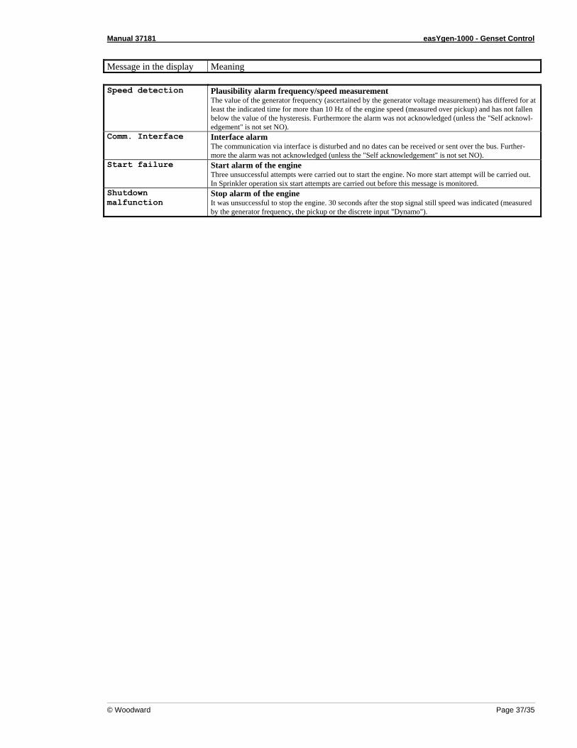
Message in the display Meaning Speed detection Plausibility alarm frequency/speed measurement
The value of the generator frequency (ascertained by the generator voltage measurement) has differed for at least the indicated time for more than 10 Hz of the engine speed (measured over pickup) and has not fallen below the value of the hysteresis. Furthermore the alarm was not acknowledged (unless the "Self acknowl-edgement" is not set NO).
Comm. Interface Interface alarm The communication via interface is disturbed and no dates can be received or sent over the bus. Further-more the alarm was not acknowledged (unless the "Self acknowledgement" is not set NO).
Start failure Start alarm of the engine Three unsuccessful attempts were carried out to start the engine. No more start attempt will be carried out. In Sprinkler operation six start attempts are carried out before this message is monitored.
Shutdown malfunction
Stop alarm of the engine It was unsuccessful to stop the engine. 30 seconds after the stop signal still speed was indicated (measured by the generator frequency, the pickup or the discrete input "Dynamo").

We appreciate your comments about the content of our publications. Please send comments to: [email protected]
Please include the manual number from the front cover of this publication.
Woodward Governor Company Leonhard-Reglerbau GmbH
Handwerkstrasse 29 - 70565 Stuttgart - Germany Phone +49 (711) 789 54-0 • Fax +49 (711) 789 54-100
Homepage
http://www.woodward.com/smart-power
Woodward has company-owned plants, subsidiaries, and branches, as well as authorized distributors and other authorized service and sales facilities throughout the world.
Complete address/phone/fax/e-mail information
for all locations is available on our website (www.woodward.com).
04/2/S