easy steps to program otp voice chip aplus
TRANSCRIPT
EASY STEPS TO PROGRAM OTP VOICE CHIP APLUS
Sound File Format Starting from a sound source file, there are three steps to prepare a voice chip samples. They are: ● Sound Editing ● Sound Compile
● Voice Chip Programming
Suppose the sound comes from CD. The sound source will have format, 44100Hz sampling rate, stereo and 16Bit per sample. We must convert the sound from CD into the following format: ● Sound file in WAV or VOC format ● 8 Bit per sample
● MONO channel
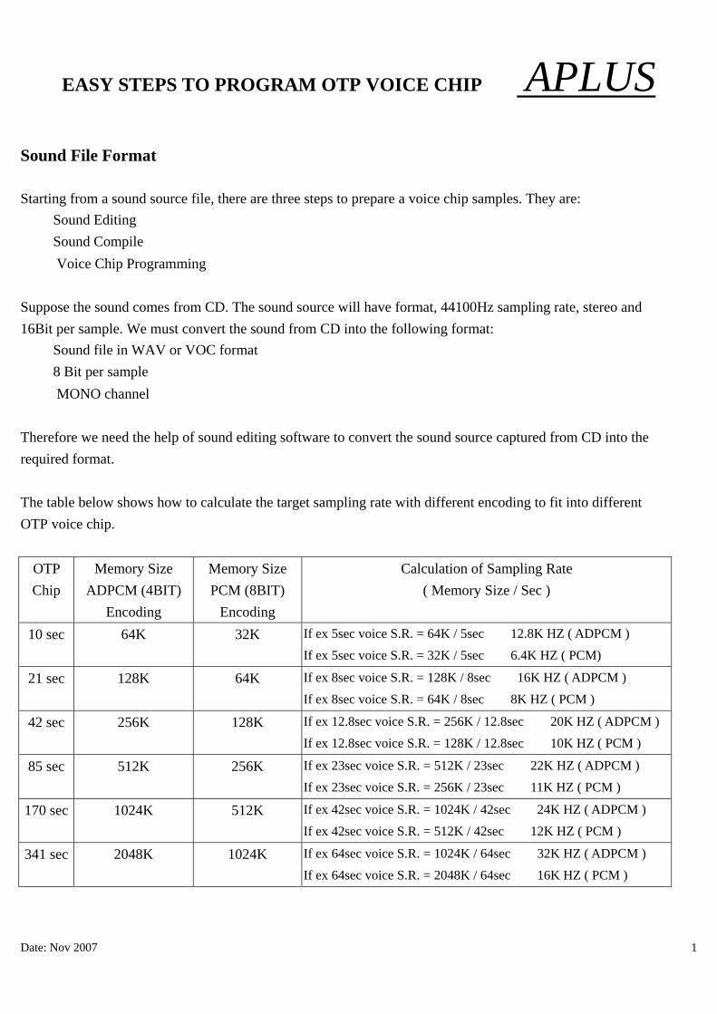
Therefore we need the help of sound editing software to convert the sound source captured from CD into the required format. The table below shows how to calculate the target sampling rate with different encoding to fit into different OTP voice chip.
OTP Chip
Memory Size ADPCM (4BIT)
Encoding
Memory Size PCM (8BIT)
Encoding
Calculation of Sampling Rate ( Memory Size / Sec )
10 sec 64K 32K If ex 5sec voice S.R. = 64K / 5sec ≒ 12.8K HZ ( ADPCM ) If ex 5sec voice S.R. = 32K / 5sec ≒ 6.4K HZ ( PCM)
21 sec 128K 64K If ex 8sec voice S.R. = 128K / 8sec ≒ 16K HZ ( ADPCM ) If ex 8sec voice S.R. = 64K / 8sec ≒ 8K HZ ( PCM )
42 sec 256K 128K If ex 12.8sec voice S.R. = 256K / 12.8sec ≒ 20K HZ ( ADPCM ) If ex 12.8sec voice S.R. = 128K / 12.8sec ≒ 10K HZ ( PCM )
85 sec 512K 256K If ex 23sec voice S.R. = 512K / 23sec ≒ 22K HZ ( ADPCM ) If ex 23sec voice S.R. = 256K / 23sec ≒ 11K HZ ( PCM )
170 sec 1024K 512K If ex 42sec voice S.R. = 1024K / 42sec ≒ 24K HZ ( ADPCM ) If ex 42sec voice S.R. = 512K / 42sec ≒ 12K HZ ( PCM )
341 sec 2048K 1024K If ex 64sec voice S.R. = 1024K / 64sec ≒ 32K HZ ( ADPCM ) If ex 64sec voice S.R. = 2048K / 64sec ≒ 16K HZ ( PCM )
Date: Nov 2007 1

EASY STEPS TO PROGRAM OTP VOICE CHIP APLUS
Voice Editing There are many different kinds of sound editing software available. We recommend GOLDWAVE, COOLEDIT AND SOUND FORGE. The following example is based on the GOLDWAVE software. Use the software to open a sound file, then followed by CUT, Paste and other commands to editing the sound. Resample the sound using the sampling rate calculated from the table above. Depends on different voice and speaker, try to find a suitable sampling rate to get best quality. When finished editing, use the SAVE AS command to convert the sound into WAV, MONO 8 BIT format. Normal, noise will be created when a sound file is sampling down into a smaller sampling rate. We usually use the following technique to reduce the noise or distortion:
● EQ, Noise Reduction, Fade in, Fade out, Volume, etc
The value setting for the above commands are not fixed. User should choose the suitable value for his/her particular sound file. EQ setting example: 60 HZ or
below Depend on situation, sometimes noise will be in this frequency rang, therefore, we need to decrease the gain of this frequency range
150 HZ Dog bark, Drum 400 HZ Male speech 1000 HZ High pitch male, female speech 2400 HZ High pitch female 6000 HZ Children 15K HZ or above
Usually, we will reduce the gain of this frequency range into minimum because our voice chip cannot response to this.
Date: Nov 2007 2

EASY STEPS TO PROGRAM OTP VOICE CHIP APLUS 1. Let’s use GOLD WAVE as an example to demonstrate how to edit the sound sources.
Open the original sound file as below:
2. Convert the sound file to the format that we can accept (WAV and 8-bit MONO)
Date: Nov 2007 3

APLUSEASY STEPS TO PROGRAM OTP VOICE CHIP
Date: Nov 2007 4
3. Save as another file name after choosing the correct format.

EASY STEPS TO PROGRAM OTP VOICE CHIP APLUS 4. Click “OK” to confirm to accept the change of file format.
Date: Nov 2007 5

EASY STEPS TO PROGRAM OTP VOICE CHIP APLUS 5. The sample rate is dependent on which IC body is used. We have the following IC bodies:
OTP CHIP
10 SEC 21 SEC 42 SEC 85 SEC 170 SEC 341 SEC
Memory Size ADPCM encoding
64K 128K 256K 2512K 1024K 2048K
To determine the SAMPLE RATE, we use the following formula: SAMPLE RATE = Memory Size / number of SEC e.g. If we are going to use the 10SEC IC, the memory size is 64K, therefore the sample rate is: 64K / 10 = 6.4KHz The maximum sampling rate should be a little smaller than the above value. Therefore, 6.0KHz
rather than 6.4KHz should be used. After obtaining the sample rate, we should resample the original sound. If GOLDWAVE is used, and assume the new sample rate is 12KHz, then, we can resample the sound file using ‘Effect’ and ‘Resample’ to modify the sample rate as shown in the figures bellows:
Date: Nov 2007 6

APLUSEASY STEPS TO PROGRAM OTP VOICE CHIP
Date: Nov 2007 7

EASY STEPS TO PROGRAM OTP VOICE CHIP APLUS 6. Normally, we will have high frequency noise introduced when we resample the original sound file. This
high frequency noise can be reduced by using the Equalizer function as shown below:
Date: Nov 2007 8

EASY STEPS TO PROGRAM OTP VOICE CHIP APLUS 7. “Noise Reduction” can be used to further remove some noise. Note that after noise reduction, the
amplitude will be increased so that the sound will be secturated.
Date: Nov 2007 9

EASY STEPS TO PROGRAM OTP VOICE CHIP APLUS 8. Therefore, we should reduce the amplitude and then apply the “Equalizer” effect once again. Use
“Effect”, “Volume” then “Change” to reduce the amplitude.
Date: Nov 2007 10

EASY STEPS TO PROGRAM OTP VOICE CHIP APLUS 9. Apply the “Equalizer” again to amplify some major sound frequency which is reduced by the previous
Noise Reduction step.
Date: Nov 2007 11

EASY STEPS TO PROGRAM OTP VOICE CHIP APLUS 10. we can apply Fade In and Fade Out at the beginning and the end of the sound to make it feel
more smoothly.
Date: Nov 2007 12

APLUSEASY STEPS TO PROGRAM OTP VOICE CHIP
Date: Nov 2007 13

EASY STEPS TO PROGRAM OTP VOICE CHIP APLUS 11. Remove the silence portion at the begin and end of the sound can reduce the chance of “POP”
sound to happen.
Date: Nov 2007 14

APLUSEASY STEPS TO PROGRAM OTP VOICE CHIP
Date: Nov 2007 15

APLUSEASY STEPS TO PROGRAM OTP VOICE CHIP
Date: Nov 2007 16

APLUSEASY STEPS TO PROGRAM OTP VOICE CHIP
Date: Nov 2007 17

EASY STEPS TO PROGRAM OTP VOICE CHIP APLUS 12. Finally, If there are very low volume part in the middle of the sound, it should be converted to
total silence otherwise, the low volume sound maybe become noise sound in the final IC.
Date: Nov 2007 18
APLUSEASY STEPS TO PROGRAM OTP VOICE CHIP
Date: Nov 2007 19
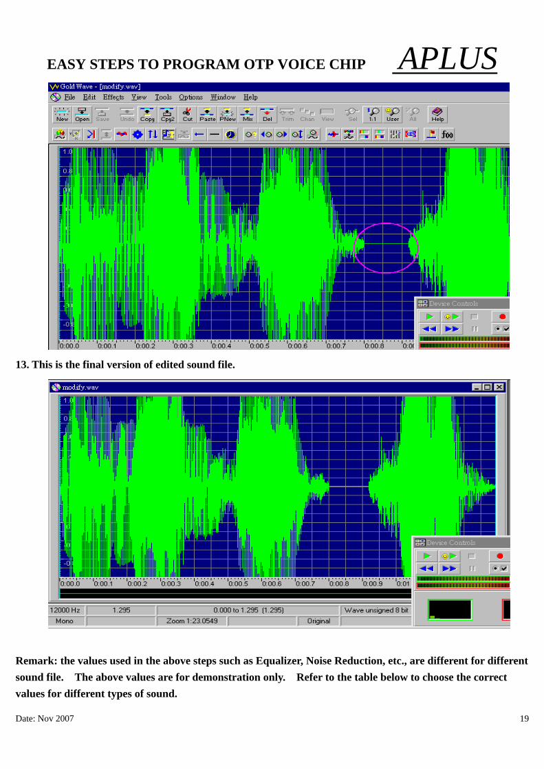
13. This is the final version of edited sound file.
Remark: the values used in the above steps such as Equalizer, Noise Reduction, etc., are different for different sound file. The above values are for demonstration only. Refer to the table below to choose the correct values for different types of sound.

EASY STEPS TO PROGRAM OTP VOICE CHIP APLUS Compile of Sound File When the sound file is prepared, the aP89W24USB software is used to compile and convert the sound file into .DPM format data file to be programmed into the voice chip. Procedures to Compile: 1. Select the suitable IC chip to be used. 2. Select the encoding method to be used, ADPCM or PCM. 3. Add the edited WAV or VOC files. 4. Select the speaker output to be used, VOUT <PWM> or COUT <DAC>. 5. Select the trigger mode to be used, CPU or KEY mode. 6. Select the number of voice groups. 7. In each voice group, select the trigger mode, LEVEL or EDGE, HOLD or UNHOLD, Retrigger or Non-retrigger. 8. Select OUTPUT OPTIONS. (busy/stop/led) 9. Double click the already added voice files into each voice group. 10. Click the COMPILE button to compile and save the above selected options and voice file into .DPM file. Function︰ Edge and Level Trigger: For both Edge and Level trigger, the chip starts to play when the trigger button is pressed. For Level Trigger, if the trigger key is pressed and keep holding at the pressed position, the chip will continue to play the same sound again and again until the trigger key is released. However, if the chip is programmed to Edge Trigger, the chip will play the sound only for one time even the trigger key is kept pressing. Hold and Unhold Trigger: For Holdable Trigger, the chip will play only when he trigger key is kept pressing. Sound playback will stop immediatly once the key press is released. For Un-holdable Trigger, the sound section will be played to finished once the trigger is pressed no matter the trigger key is kept pressing or released. Non-retrigger and Retrigger: For retrigger option, the currently playing sound will be stoped and new sound section will be played when another trigger key is pressed. For non-retrigger option, new trigger action will not be granted until the current sound section is finished playing.
Date: Nov 2007 20

EASY STEPS TO PROGRAM OTP VOICE CHIP APLUS
Date: Nov 2007 21
PWM or COUT: PWM output is used to drive a small speaker ( < 1/2 W speaker) directly. That means user can connect a small speaker to the VOUT1 and VOUT2 directly without adding extra circuit component. However, the sound volume will be limited. On the other hand, COUT is a current mode analog output in which at least a NPN transistor is needed as a amplifier. More high power amplifier can also be used with this COUT output to obtain larger power output.
OTP Chip Programming Go the Writer page, press the LOAD button to load the .DPM file into the software. Note the CHECK SUM value. It should be the same as the value after Compile. If it is different, that means the .DPM file is corrupted. Voice files must be compiled again. Insert the suitable chip into the PC programmer socket and press the WRITE OTP button to start the programming. Upon finished, a 100% match should be display. That means the voice chip is programmed successfully.