east naval facilities lwclfssified ee/e/lell//hi
TRANSCRIPT

RD-RI67 45? EAST COAST TACTICAL IRCREN COOT TRAINING SYSTEN 1/2FAILITY EXPANSIO CON..(U) NAVAL FACILITIES
ENlINEERIN8 COMMAND HRSHINGTON DC CHESAPEAKE..LWCLfSSIFIED T OYLE SEP 81 F/O 13/18 N
EE/e/lEll//hI/lllllllllllEllllllllEEllE
IIIIIIIIIIIIIu

.p]
a.-
1*1128 12I- L -'
1I1I 1- 111111- IIII
111.25 L 111 .
M'(Rn "009T,

FPO O
DIs,
EAST COASTTACTICAL AIRCREW COMBAT
TRAINING SYSTEMFACILITY EXPANSION
CONCEPT STUDYLgn
to
Ocean EngineeringaiESAPEAKE DIVISIONNAVAIL FACILITIES ENGINEERING (X)MIANDWASHINGION NAVY YARD
8.~. wASHINaI7JN, DC 20374
OTICE-LECTEMAYO0 51988
ON STATEMENT ADA, LHI ot puablic 1010aw
Lxr= Udambw4
'1

-- : TACTICAL AIRCREW COMBAT..- ~~TRAINING SYSTEM.-.--.. FACILITY EXPANSION~~CONCEPT STUDY -"
U• -.- .-
• ," OT. J. O'BOYLE
TTIC::: FPO-1-81 (26) F'IELECTE I!
""~~ D..'.1
OCEAN ENGINEERING
AND CONSTRUCTION PROJECT OFFICE'":"" ~CHESAPEAKE DIVISION""-
NAVAL FACILITIES ENGINEERING COMMANDWASHINGTONDEC 20374
~pi~m lo pablaoid-aa

DISCLAIMER NOTICE
THIS DOCUMENT IS BEST QUALITYPRACTICABLE. THE COPY FURNISHEDTO DTIC CONTAINED A SIGNIFICANTNUMBER OF PAGES WHICH DO NOTREPRODUCE LEGIBLY.
d.
.* . .. -.-

UnclassifiedSECURITY CLASSIFICATION OF THIS PAGE
REPORT DOCUMENTATION PAGEla. REPORT SECURITY CLASSIFICATION lb. RESTRICTIVE MARKINGSUnclassified
2a. SECURITY CLASSIFICATION AUTHORITY 3. DISTRIBUTION AVAILABILITY OF REP.Approved for public release:distribution is unlimited
2b. DECLASSIFICATION/DOWNGRADING SCHEDULE
4. PERFORMING ORGANIZATION REPORT NUMBER 5. MONITORING ORGANIZATION REPORT #FPO-I-81(26)
6a. NAME OF PERFORM. ORG. 6b. OFFICE SYM 7a. NAME OF MONITORING ORGANIZATIONOcean Engineering& ConstructionProject officeCHESNAVFACENGCOM
6c. ADDRESS (City, State, and Zip Code) 7b. ADDRESS (City. State, and Zip )BLDG. 212, Washington Navy YardWashington, D.C. 20374-21218a. NAME OF FUNDING ORG. 8b. OFFICE SYM 9. PROCUREMENT INSTRUMENT INDENT #
8c. ADDRESS (City. State & Zip) 10. SOURCE OF FUNDING NUMBERSPROGRAM PROJECT TASK WORK UNITELEMENT # # # ACCESS #
11. TITLE (Including Security Classification)" East Coast Tactical Aircrew Combat Training System Facility Expansion Concept
Study12. PERSONAL AUTHOR(S)T.J. O'Boyle13a. TYPE OF REPORT 13b. TIME COVERED 14. DATE OF REP. (YYMMDD) 15. PAGES
FROM TO 81-9 11016. SUPPLEMENTARY NOTATION
17. COSATI CODES 18. SUBJECT TERMS (Continue on reverse if nec.)FIELD GROUP SUB-GROUP TACTS, East Coast Tactical Aircrew Combat
Training System
19. ABSTRACT (Continue on reverse if necessary & identify by block number)This brief study was performed as per the request of the naval Air SystemsCommand. This report presents the results of a facility concept study andpreliminary cost estimates for the future expansion of the East Coast TacticalAircrew Combat Training System (TACTS). The present TACTS is located (Con't)20. DISTRIBUTION/AVAILABILITY OF ABSTRACT 21. ABSTRACT SECURITY CLASSIFICATION 3
SAME AS RPT.22a. NAME OF RESPONSIBLE INDIVIDUAL 22b. TELEPHONE 22c. OFFICE SYMBOLJacqueline B. Riley 202-433-3881DD FORM 1473. 84MAR SECURITY CLASSIFICATION OF THIS PAGE
7.," . .. . . . . .... ,.

S o . .. .. . .3 " . •
BLOCK 19 (Conbt)
approximately 30 miles east of Kitty Hawk. North Carolina. and consists offour template type towers. These towers are in 81 ft., 93 ft.. and two towersin 105 ft. of water. The direction of the proposed expansion is unknowntherefore, the exact water depths at each new remote location is uncertain.These water depths could range from 150 ft. to 6000 ft. depending on thedirection of expansion. Each proposed expansion would require as many asthree new remote structures and would use the existing TACTS towers as themaster stations for these remotes. The study considered vertical extensionsto the existing towers to facilitate required line of sight microwave datatransmission to and from range expansion units. Expansion areas consideredresulted in conceptualizing structures for shallow and deep water conditions.
S
................................................

EAST COAST TACTICAL AIR CREWCOMBAT TRAINING SYSTEM
FACILITY EXPANSION STUDY
SEPTEMBER 1981
T. J. O'BOYLF
Approved: S. C. Ling, DirectorEngineering Analysis
Division
OCEAN ENGINEERING AND CONSTRUCTION PROJECT OFFICE
CHESAPEAK~E DIVISIONNAVAL FACILITIES ENGINEERING COMMAND
WASHINGTON, DC 20374

TABLE OF CONTENTS zi
1.0 NTRODUCTiON 1
1.1 Scope of Report 11.2 Criteria I
1.2.1 Environmental 11.2.2 Expected Life 31.2.3 Antenna Excursion and Rotation 3
1. 1.3 Concepts 31.3.1 200 Ft. Tower Extension 31.3.2 Shallow Water Range Expansion Structure 51.3.3 Deep Water Range Expansion Structure 5
2.0 THE 200 FOOT EXTENSION CONCEPT 5
2.1 Stability of TACTS Towers with the 200 Foot Extension 52.2 Preliminary Cost Estimate 6
3.0 SHALLOW WATER RANGE EXPANSION CONCEPT 8
3.1 Floating Structure Concept 8" 3.2 Fixed (Template) Structure Concept 9
3.3 Guy Wire Tower Concept 9
* 4.0 DEEP WATER RANGE EXPANSION CONCEPT 11
4.1 Semi-Submersible Concept 11* 4.2 Spar Buoy Concept 11
4.2.1 Stability Analysis 114.2.2 Preliminary Cost Estimate 16
5.0 CONCLUSION 17
5.1 200 Foot Extension Concept 175.2 Shallow Water Range Extension Concept 185.3 Deep Water Range Extension Concept 185.4 Floating Structure Maintenance 19
5.5 Summary of Preliminary Cost Estimates 19
REFERENCES 20
* i APPENDICES
A. 200 Foot Extension Stability Analysis and Cost Estimate* -B. Wave Forces on Guy Wire Tower and Preliminary Mooring Analysis
C. Spar Buoy Displacement During Operational EnvironmentD. Spar Buoy Displacement During Survival Environment
....-. .- L..

LIST OF FIGURES
S Filh,
1.0-1 Index Map Showing Approximate Location of TACTS Towers 2
1.0-2 200 Foot Tower Extension 4
2.0-1 Location of Two Proposed Expansions 7
4.0-1 Semi-Submersible Concept 12
4.0-2 Semi-Submersible Mooring Concept 13
4.0-3 Sketch of Spar Buoy Concept 14
Accesi 1 For
NTIS CRA&
DTIC TABUnannounced 0Justification
.. .. .. ... .
B Y .. . ...... ....Ditibto

7 .w
LIST OF TABLES % %
2.0-i Stability of TACTS Offshore Towers with 200 Foot Antenna Extension 6
2.0-2 Preliminary Cost Estiamte of the 200 Foot Antenna Extension 8
, 3.0-1 Preliminary Cost Estimate for the Guy Wire Tower Concept 10
4.0-1 Prelinimary Cost Estimate for the Spar Buoy using Kevlar Mooring Lines 16
4.0-2 Preliminary Cost Estimate for the Spar Buoy using Polyester Mooring Lines 17
5.0-1 Summary of Preliminary Cost Estimates 19
i.
I"--
p-
I--
p.-.. . .

d" .
,•. 1.0 INTRODUCTION
1.1 Scope of Report
This brief study was performed as per the request of the Naval Air Systems Command.
This report presents the results of a facility concept study and preliminary cost es-
timates for the future expansion of the East Coast Tactical Aircrew Combat Training Sys- -. ,
tem (TACTS)*. The present TACTS is located approximately 30 miles east of Kitty Hawk,
. North Carolina and consists of four template type towers. These towers are in 81 ft.,
93 ft., and two towers in 105 ft. of water, (see Figure 1.0-1).' The direction of the pro-
posed expansion is unknown therefore, the exact water depths at each new remote location is
uncertain. These water depths could range from 150 ft. to 6000 ft. depending on the
direction of expansion. Each proposed expansion would require as many as three new remote
structures and would use the existing TACTS towers as the master stations for these remotes.
The study considered vertical extensions to the existing towers to facilitate required line 3Wof sight microwave data transmission to and from range expansion units. Expansion areas
considered resulted in conceptualizing structures for shallow and deep water conditions. - -
1.2 Criteria
1.. 1.2.1 Environmental
For this study, it was assumed the environment in the proposed range ex-
pansion areas would be similar to the criteria used for the design of the existing TACTS
Towers. Some modifications to these criteria were made for the different water depths. A
*Formerly named East Coast Air Combat Maneuvering Range (EC/ACMR)
. . . - .. 5* *5' - . - . 5 5 5

V i, e I.-1 mdX Map Shiwing Approximate Location of ~~
4o 31) 4C
I VI
2 .NLW 93 FT(
T.F
A.A..
0 TIDE GlAUri
S ~' ..~'k ~MLW 81 FT. 434
CAI~CSCALE
-I~1
K oV40 200 so 4 0 so
StrucUtuCA, No.~ 2 S
-Distance to Shore (Nau. Miles) 16.0 23.5 31.5 20.0~
2
listing of the assumed environment used in the analysis of the guy wire tower concept and
the spar buoy concept can be found in Sections 3.3 and 4.2.1, respectively, of this report .
1.2.2 Expected Life
P It was assumed that the structures would be designed for a 20 year life.
1.2.3 Antenna Excursion and Rotation
NAVAIRSYSCOM indicated that the horizontal excursion of the floatin"
structures would not be of concern because it would be possible to track and locate each
structure. The limiting factor in the amount of antenna rotation (pitch and yaw) that can
be tolerated is the antenna beam width. For this report it was assumed that the antenna
rotation would be limited to approximately + 100.
- 1.3 Concepts
1.3.1 200 ft. Tower Extension
The use of some of the existing towers as the master for the proposed TACTS
|- expansion necessitates the fabrication and installation of an extension to the struc-
tures. Because the TACTS range uses microwave transmission to relay the data from the re-
. mote stations to the master, the receiving antenna on the master must be at a high enough
elevation to allow line of sight operation with the remotes. Adding a 200 ft. extension to
the deck of the existing TACTS tower, to be used as the master, raises the antenna to an ele-
vation of 275 ft. above the water, (see Figure 1.0-2), and keeping the antennas on the new
remotes 75 feet above the water surface results in an approximate line-of-sight separation
distance of 26 NM.
3

-Ir
* 1
.%
qE 7ic/ i;,'--
Fra EA?~A5-A, 1/2
7-r'7/

1.3.2 Shallow Water Range Expansion
" For water depths less than 200 ft., either a floating or fixed structure
" could be used. The floating type would have to be one with relatively shallow draft, similar ,
to a semi-submersible. The fixed structure could be either a template structure like the
-. original TACTS towers or a guy wire tower. The guy wire tower concept was considered to be
feasible. This study concentrated on the guy wire type of shallow water structure because of
-" this task's short time frame and as stated above, the existing TACTS towers are of the tem-
7' plate type.
*: 1.3.3 Deep Water Range Expansion Structure
For the areas where the water depths can reach 4000 to over 6000 ft., the
only viable remote structure would be of the anchored/floating type. There is no evidence
that any unmanned, floating structure with these operational criteria has ever been moored
in these water depths for an extended period of time. Therefore, there is no way to place a
risk factor on this concept but the risk cannot be ignored. Two possible types ofU- floating structure designs are the semi-submersible and the spar buoy. Either type may per-
form equally well and conform to the operational criteria, however, the spar buoy was the
concept investigated in this report.
2.0 THE 200 FOOT EXTENSION CONCEPT
2.1 Stability of TACTS Towers With the 200 Foot Extension
,-o.
The construction and installation of the four offshore towers of the Tactical Jk
Aircrew Combat Training System (TACTS) was completed in August 1977. The location of
5 I

S the towers and two of the proposed expansion areas are depicted in Figure 2.0-1. Four
years of operational experience have revealed over water data transmission problems in tht
existing tracking system which made it necessary to consider an engineering change to the P
- original towers. The suggested solution to these problems is addressed in reference (W,
and this solution was to put a 100 ft. extension on the structures. However; these exten-
sions were never installed. The stability calculations for the now proposed 200 ft. exten-
S.-sion, presented in Appendix A of the report, are an adaptation of the work done in references
(1) and (2). The factors of safety from these calculations are presented in Table 2.0-1.
The factor of safety for compression failure is relatively low for the deeper water depths
but this is for a short term loading and is felt to be adequate.
TABLE 2.0-1
Stability of TACTS Offshore Towers with 200 foot Antenna Extension:
b TACTS Offshore Water Factor of Safety forTower Depth Pile Foundation
Tension CompressionFailure Failure
1 81 feet 1.61 1.42
2 93 feet 1.44 1.20" 3&4 105 feet 1.41 1.19
2.2 Preliminary Cost Estimate
4" Reference (1) had indicated the 100 foot extension could be preassembled
S'. on shore in sections and transported to the erection site by helicopter. This procedure
0"- -would not be possible for the 200 ft. extension because the weight of each section could
exceed the lift capacity of the helicopter. Also, the top deck of the TACTS Towers would
have to be modified to accept the stand alone 200 ft., extension and an additional walk-way
6
....

I-PF
'*~~~~L 05 3F 0' 4 0 2
t o ., 4'
CA40IN tMLW fr FT.
/ 10NAUTICAL Wt.E
1(~ 4 0 60 400 ICONIOUR 0(PI.S INI FAlWous I1
7. 5'0 020 10 75 o40 30'1
12N

- . - - . - -. . - S V~j- -- . - .
: be placed around the perimeter. This tower modification would be a separate installation
and could be preassembled and brought out on a barge then raised into place by a crance
and welded on. Table 2.0-2 presents a preliminary cost estimate summary. A detailed
breakdown of this cost estimate appears in Appendix A.
TABLE 2.0-2
Preliminary Cost Estimate for the 200 foot Antenna Extension:
Material $124,500Labor 126,160
InstallationPlatform Mod 67,800
' Tower Extension 173,550
$492,010
A&E Platform Mod &Tower Design 10% Above $ 49,200SIOH 107 Above 49,200
$590,410
TOTAL (9/81 Present $) $600,000
NOTE: Does Not Include Antenna Cost
3.0 SHALLOW WATER RANGE EXPANSION CONCEPT
3.1 Floating Structure Concept
As stated earlier in this report, a floating structure would have to be de-
'• signed as a semi-submersible because a shallow water depth requires a structure with a
small draft. A spar type structure requires a much greater draft and may come dangerously
8 •
i~i i):'8

close to the sea bottom during a storm. The concept of using a floating structure in
shallow water was not addressed in this study.
3.2 Fixed (Template) Structure Concept .4..
This concept uses the same type of structure in the shallow water areas as
used in the original TACTS range. During a phone conversation with Tera, Inc., on 1 September -I.
1981, it was indicated that a jacketed structure for shallow (150') water may cost $5M each.
" This was a very rough cost and would be for an existing used structure that would be bought
as is. There would be no design, fabrication, or construction control. These structures
would be transported to the site, off loaded into place, and piles driven through the jacket
- to hold it in place. This may be a good concept if the funding is available and the schedule .
is such that the structures are needed quickly.
.. '
" 3.3 Guy Wire Tower Concept
This concept places a slender tower in the ocean and holds it upright with
. mooring lines that are under tension. The guy wire tower was modeled as a cylindrical pile,
Pinned at the sea floor and held rigid at the point where the mooring lines are attached.
L The survival environment assumed was as follows:
Water Depth 100, 150 amd 200 ft.
Wave Height 61.3 ft.
Wave Period 13.6 sec.
Astronomical Tide 4.4 ft.f.* I",.
Storm Tide 3.3 ft.
" Surface Current 4.7 ft./sec.
- I9

The wave force distribution for these water depths on a 24 inch and 36 inch-4,
Idiameter column were calculated. The results of these calculations can be found in
* Appendix B. The wind area above the work platform was calculated assuming there would
... be the same assemblage of material as found on the TACTS towers at present. For this
report, the wave forces were placed on a 36 inch diameter pile in 100 feet of water to
determine the horizontal force the anchors would have to overcome. Also, this horizontal
force was needed to do a preliminary design of a mooring system. This concept uses a three
legged chain mooring. It is important to not, that no analysis of the antenna movements was
,' performed and this may not be the final mooring configuration and may indeed contain many
more legs. The total horizontal force and mooring calculations can be found in Appendix B.
Based on the above concept assumptions, a summary of the preliminary cost estimate can be
found in Table 3.0-1.
TABLE 3.0-1
Preliminary Cost Estimate for the Guy Wire Tower Concept:
Site Survey $ 50,000 -'. o
Material, Construction Tower,Stake Pile Anchor, New Chain 517,000
Installation (25 Days)Equipment 537,700Labor 111,700
1,166,900
A&E Design 6% AboveExcept Site Survey 70,000
SIOH 10% Above 116,000
TOTAL (Present $) $1,403,600
NOTE: Does Not Include Post Installation Inspection
."
lO. ,'. ... . . . . .

4.0 DEEP WATER RANGE EXPANSION CONCEPT..; ..
4.1 Semi-Submersible Concept
This report does not evaluate the semi-submersible concept. It was felt
that the short time allotted for analysis of the deep water areas would be best spent on
the spar buoy concept. Furthermore; Alan C. McClure Associates, Inc., investigated the
semi-submersible (see Figure 4.0-1), and reported their findings to NAVAIRSYSCOM. There was
no time to look over their concept to see if ti conformed with the operational criteria or
if their proposed mooring system was strong enough to withstand the environmental loads (see .-.
Figure 4.0-2).
- 4.2 Spar Buoy Concept
4.2.1 Stability Analysis
The preliminary concept shown in Figure 4.0-3 was analyzed ut dr
the environmental operational conditions listed below:
Water Depth 6000 ft.
. Wave Height 40 ft.
Wave Period 13.6 sec.
Surface Current 4.3 ft./sec.
Bottom Current 1.3 ft./sec.
Wind Speed 60 mph.
11 " '.

-. . .~
g~.
S 8I, 11A I
~- I --- -*
a
1~~~~~
- I
I..-..I ~
~Cr~ .- , ;4
k \.~ .4 C. ** .~. -*
-~--:~ iKS IS~ N~~*) I
V C.
illa
V
. . te..
B...
K '~- !..I~i7**~1 A
0 ---~'k -% -.
K
a~
4.
I'
12

o-'-
' ... ...
K .
,- . ._ .2. ' -
'-...
."
£" K). . " ...
,. .*
I . - + ' , .
•-: , -, I -
..'I .., .,.
',.
-.
• °I- 4
li-- ..- "I, Je
-, -. , , I.! ..-t, ,," .-,.. / ,' ".
• " . ,
I' ! 7 ,13

-~~~~~P- ,
.. . ... . . .
%A
A/.
I- Tr'Ar Ak AOA
wz/
A- ~oP.7T,~A '1' 14

It was found that the baffel placed below the anchor attachment points
did not contribute enough of a compensating force to offset the overturning forces. Be- -:
cause of this, the baffel was replaced with an equivalent weight which was moved further
below the primary floatation. This resulted in a much greater separation between the
center of buoyancy and center of gravity. This increased separation produced the needed
righting moment.
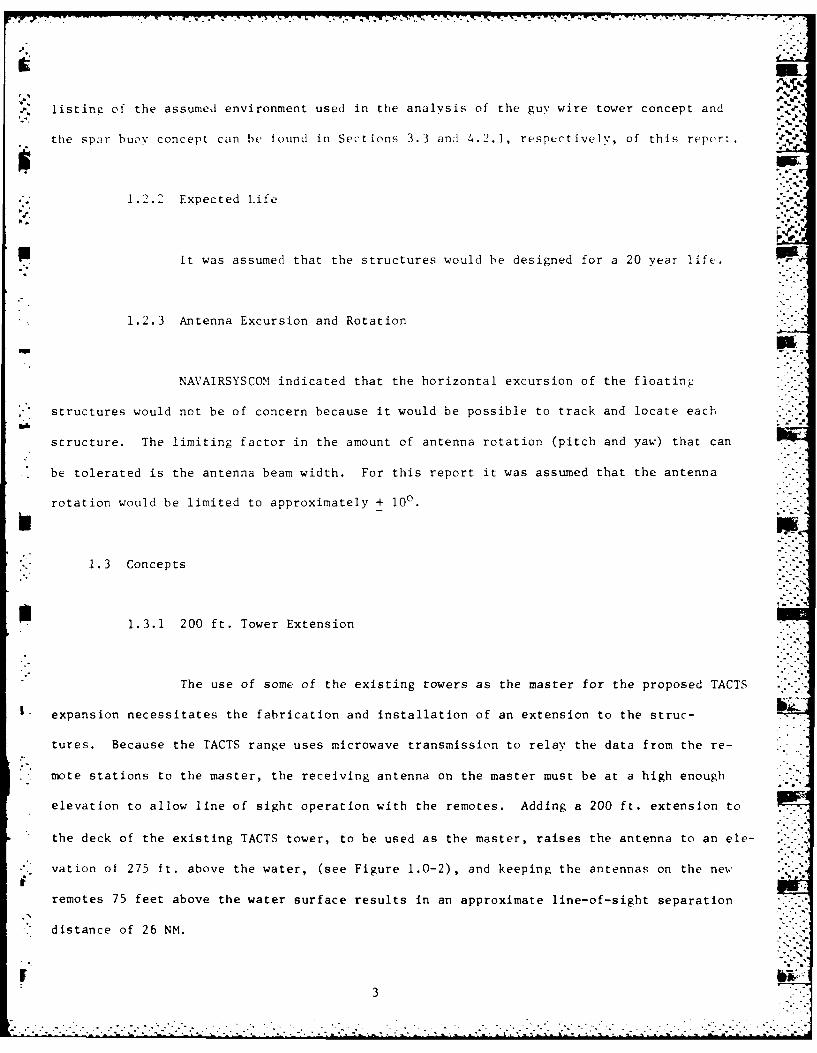
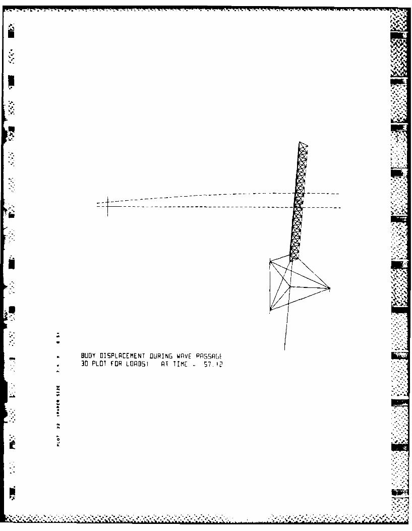
The revised structural configuration was subjected to the operational
environment and five consecutive waves to determine if the concept would conform
to the ± 100 roll, pitch and yaw constraint. The analysis indicated the structure
assumes an initial angle of approximately -5.50 due to the wind and current. Fron"
this initial angle the variation in pitch ranges from -10.50 to 7.80. The yaw is
less than + 10. The pitch may be reduced by further separation of the center of buoy-
ancy and center of gravity. A series of plots depicting the time history of the structure's
movement can be found in Appendix C. After five waves had passed, the structure
had moved along the water surface in the direction of the wave and current a distance
of approximately 185 feet.
It is important to remember that the results presented in this report are
for only one environmental loading condition. The chosen wind, wave, and current direc-
I. tions may not result in the maximum load but give an indication of the structure's response.
Preliminary analysis done on this concept, assuming the structure
did not move, resulted in mooring line loads as high as 250,000 pounds for the sur-
vival condition. Allowing the structure a limited amount of movement in both the opera-
.tional and survival environment results in lcwer mooring line loads of approximately."'l
150,000 pounds during operation and approximately 160,000 pounds in survival condi-
[7.

.tions. The plots of the structure's movement, found in Appendix D, for the 61.3 foot.
survival wav, and 150 knot survival wind show the angle of pitch has increased.
However, this increase is not enough to endanger the top deck on the tower. Also, the
.structure had moved approximately 320 feet after the five waves have passed. This lower
mooring line load during the survival conditions results in a lower overall cost estimate.
No stiffness analysis was done on the structure for this report. It is
-assumed the individual members within the structure can be choosen so each will be strong
enough to withstand the maximam loads.
4.2.2 Preliminary Cost Estimate
The first cost estimate prepared for the spar buoy concept was based on
" the original mooring line load of 250,000 pounds (see Table 4.0-1). It was also decided
to use a Kevlar mooring line which has very little elongation. As seen in Table 4.0-1,
..the 3 Leg mooring cost is the most expensive part of this concept.
TABLE 4.0-1
Preliminary Cost Estimate for the Spar Buoy using Kevlar Mooring Lines.
Site Survey $ 150,000,.Material, Construction 800,000
3 Leg Mooring 5,216,000Installation (15 days)
Equipment 307,000Labor 60,250
- A&E Design 67' Aboveexcept site survey 383,000
SIOH 107, Above 638,325
TOTAL (Present $) $7,554,575
.,NOTE: Does Not Include Post Installation Inspection
16 ~1

tN
Allowing the structure to have limited movement reduced the loads on the
mooring lines. This load reduction together with the possibility of changing the mooring
. line material to a Polyester may substantially lower the cost of each moored structure.
The polyester (Stable Braid) mooring line has approximately 2.5% elastic elongation .7"
when used at 20' of breaking strength, which is the working (operational) load.
This is the lowest stretch standard double braid rope available. Table 4.0-2 is
a summary of the cost estimate for the Spar buoy concept with the reduced mooring lint
loads and replacing the Kevlar with the polyester mooring line.
TABLE 4.0-2
Preliminary Cost Estimate for the Spar Buoy using Polyester Mooring Lines,
Site Survey $ 150,000
Material/Construction 800,0003 Leg Mooring 2,123,000
Installation (15 days)Equipment 307,000
I Labor 60,250A&E Design 6/' Above
except site survey 200,000SIOH 10% Above 330,000
TOTAL (Present $) $3,970,000
NOTE: Does Not Include Post Installation Inspection
5.0 CONCLUSION
5.1 200 Foot Extension Concept
Placing a 200 foot, stand alone tower extension on the existing TACTS towers
could reduce the factor of safety for compression failure of the pile foundation to 1.19.
17

rJ Because the environmental loading condition responsible for this reduction in safety factor
would not be long term, this value is felt to be satisfactory. This factor of safety was
U calculated based on the original strengths of the TACTS towers. Prior to the design of the
- extension, an extensive engineering analysis would be needed to ensure the towers have
retained 100/ of their original strength.
*5.2 Shallow Water Range Expansion Concept
The use of a template structure would be the option with the lowest risk factor.
The continuing successful use of the present TACTS range indicates this type of structure
can endure the environment.
The installation of a guy wire tower may involve unseen probles that
would increase the cost. As mentioned earlier in this report, the guy wire tower
may have many more mooring legs than the three used in this report. This concept
appears to have a lower preliminary cost estimate but there is a much higher risk factor
- with this concept than there is using a template structure.
The use of a floating structure was not addressed, therefore, the adequacy
of this concept cannot be determined.
5.3 Deep Water Range Extension Concept
There is no way within the timeframe of this task to place a risk factor on this
concept because no one has ever moored an unmanned platform, like the ones described in this
.. report, in this water depth. The technology exists to accomplish the design and installa- N"
18
-," " 18
4, *, 4*.,4*. - ."." .. . . . . . . . . . ....'.-.".. . . . . . ..-- .. v.. --..-."-. ....- ..- :...- . -...--... ,.--... -..---. .: .. ,- -, , .. .- ,- -. ,..'-'4

,,..- ..- .,., r - - -: . . ,: ....rr r r r r ,r..-- -- . r .:.v-, r 4-tp
-,. ,u -- a" " ' . 7IL n-, ve..Nw
tion of this type of structure, however, the lack of experience could contribute to making
this a very high risk undertaking. Even so, it is felt this concept could be successfully
engineered. It is also important to consider that during the life of the structure, part or
-. all of the mooring system may have to be replaced.
P. 5.4 Floating Structure Maintenance
During the design life of the floating structures, each one should be
removed from it's mooring and brought back to shore every five years. At this time
" the entire structure could be refurbished. The cost of this maintenance was not
- included in the cost estimate. Also, the impact of the down time for the range while this
maintenance is being done has not been factored into the estimate.
5.5 Summary of Preliminary Cost Estimates
A summary of all the preliminary cost estimates can be found in Table 5.0-1.
All the costs presented in this table are based on assumptions presented in this report. Zr.
TABLE 5.0-1
L, Summary of Preliminary Cost Estimates
Concept Present $ Cost
.-1 200 Foot Extension $600K
Fixed Template Tower $5,000K
Guy Wire Tower $1,404K
*, Spar Buoy Using Kevlar $7,555K
Spar Buoy Using Polyester $3,970K
19-
"' " "-,- .' '" % ' ,:,"• . - .. . -" .'.'.- . . ,-. . . . .. . -. .-. . . . . . . .. . .. .-

REFERENCES
1. Tactical Aircrew Combat Training System (TACTS) Antenna Extension Feasibility Study,FPO-I Technical Note TR-lE-40, January 1980 " .
* 2. Chern, C., Feasibility Study on the Construction and Cost Estimate of an Offshore* .* Microwave Antenna Support Tower, Key West, Florida; FPO-l, October 1980
.-
! : ' " : : -:.. . -
.4L 7
-'i ..3
20
-" -

.4
Hi Ax
~.
p
~ *~* -
.4.'
w

CHESAPEAKE DIVISION PROJECT: . - 2W'.Naval Facilities Engineering Command NOW Station:DISCIPLIf f- ' E S R: Contract:
I Calcs madc by: date: alculations for:Calcs ck'd by: date: - X ,.. - .j
rr
.... , :-.:::
.. " . . _._' -o --- _ ,: :--a . _-,,-', -..\- ;., _.' '-. .-,a %"N\ C4-
" '4-'-'
.4,, ,- r.-, I,.: , -
! -
II.. _o C _-_ ] ..':
p- f.-f
%,.0 -.145
r °

I '- '.
it.,.,'.. .. --- _ 4"-.
I -
.,-- / * 4 ,: I (I..,.:J
b '
UL_ f >"JL.. .
• " - ..-4
.. ] ~-''
• "%
. i -I
C ,t ,:,,0.' , "' 'jj • .7"
....I ..
:':'ViiL j. , 'v ' z ¢,.;' : 4 -:',:'
.. ,, , :....:,
,4,4%
- • ". * ," 4:'

Jc,
OF1:I
7c vp.V7.
p R 1, f,--S
~-r , . (A)-~,j. '~' s o ~ 1399j ', K-,
C)(
6 J 1 ___I43Ko1H 2-- c6Zo291, 9,3bo T7.4_7
2-- !9 Iif I b-Z' 14 __ -7b' ~ ,900 ______ bojeo*
N~ K
Ta ( O -7 T- 0 1 &-C ArO E 443( w ')iL')E

- - - - J- FT.
A
Zo -7 7 6 "
_____~3 ___ __ 4% __ __
77-*

ip 4
--7
A~~A IS c15& ~z-3
.~,1 5 ---
________ ____ __ 54,Z 9.~4 99C - 7 Z..,9
_I-.- ;_______ 7203 t Z~ IQ3D 8-2,2Z7( M______ .00
::_ __ 97,7 0 1o4,6 7b 14.o9 IV.•'I .<-_ / ,-- tI2.,(oo i2o, 3Z ' 3.zZ t4 ,
.<,0 3 - .
I_____ 1 141, 17 I3,733 Ito.71 19.2(
.uA2--- 1- , .71,"b44 (b,0) 17. 4-
1-7 _ _ 1"71,44 ( 1 9,0o3 1 _7.6_ 19.__ -Z-
L
.. f* " .-. ].i+ .%

X- A-, I
r-rec-ST-~ ~ ~ ~ ~ R.-.i-rNo -7/
co"e p
Ph
P's

- - - - -- '.r- r-.y . -!.f
-A,
.* - l
I.,-
.'-J ' ,~ "; / -- <:: "' c :. . .- ,- "- ',"7. " -
.: .. .. . . .- ~ .. . . . . . ... .. K. .?-
-.--. .
"P.....:._./ I
* .-- C'~ / -.,/. ",
i ! ' -.- A --
* , . " ",. U , _ , .U. -",._ -.
- -1.4/°
,- /. - ---- *
. ...- A 4 .,....,,

pp
V74
PA<
li7

L CHESAPEAKE DIVISION PROJECT: WkC -.
Naval Facilities Engineering Cemmand NOW Station: -"-DISCIPLItL: E S R: Contract: _ ___"
Calcs made by: I date: Calculations for: .-
Calcs ck'd by: date: ",____
S": VNkli:.- CV C__ \.. Q\ . '-. -,
I~~ IfjQ Le
'4.J
[7 dE.. -,2.. -'- Z7-/---g- .f
:. b\ (to ' ,.... ,,.,'- .~k . 1, Y. q090, ,*62 -.:
-I

CHESAPEAKE DIVISION PROJECT: -t~(~
Naval Facilities Engineering Command NDW Station: ________________
DISCPL r- hk E S R: _ ____Contract:________
Caics ma~de by: ~.w ~date -.-~- Calculationls for: :!''~~-vCaics ck'd by: date:____ ______________________
~~L\
±1" ofZ ~
S* 4-5

- .-.- •, ."" "'Z ' _%[ '
-
7 'F" -r - .v -% -r
CHESAPEAKE DIVISION PROJECT:--v .Naval Facilities Engineering Cmmand NOW Station: __"-DISCIPLIE- E S R: Contract: "__ _
Calcs m ade by: V ,- date: I-1 \ Calculations for: ; - _ ,T m - ,Calcs ck'd by: date: ____
P--c '.,--_ ,-c.- C .c's-- V ,.-- -v -tA-W ?ct ~U ,-.:
W y~. C ._ i4 9o : :7 -i - :slAM z\~k~LL L O 1c 0 0 z
C L C V-- C)Li LF'L j3~ P- C." T -0
1t 0 x-
iC
pag L of •
GPO 042-.51
................--...-.

CHESAPEAKE DIVISION PROJECT: c'*Naval Facilities Engineering Coin d NDW Staton: _______________
DISCIPLI[ E S R: ______Contract: ________
G aics made by: ' ~ date: c , Calculations for: :c-f 7-1-~-~n (.TV X* Caics ck'd by: date:___________________________
CA(
Co- ip e t-*' X-LL
____7n,, c:
h IF-
ct
qo c)-* TLV 5, L I t4.

I CHESAPEAKE DIVISION PROJECT: £6_. -,T# .
Naval Facilities Engineering Command NDW Station: .--.__ _
DISCIPLINE x/' , -/ E S R: Contract:Calcs made by: 7o 4//r date: / Calculations for: -,.____
.Calcsck'd by: date:.
-7-77°/ 1. -5
.,' _4' -,m#c-'-""
/d7L5
l -IVo 6 Z " "
..- -,. .- :
.-i I->
Q; 6v °z- :s,/.
/ ~/ ~77r,

. .. -.. .; .7--. - - . . . .. . . .. .'-. - r. , - v7- wr
::* CHESAPEAKE DIVISION PROJECT: ; ,7,t. -Naval Facilities Engineering Command NOW Station: _ _:__ _DISCIPLINE /' IJ / E S R: Contract:I
P. Calcs made by: 7. O '2 i/e date: 5?2Z -/'l Calculations for: _ _7.._ _
Calcs ck'd by: date: _ _ _ ___ _-_-_
A _"' _T____________,__,_,,,________---__.______._._
c?-r.::1 , 7 : .
-3 r3D --e derne'.14::
- Y 7 4:''/ z *-
+7)Cd,*f.~C~ _______::-:-:
70~~~~% 5-./1el 7f-
f-I8) rOW Ex~c~,',"I
I " ob Z o . 0, u X c4, ""
3 3 e7
k .." e -,ic 4vpr
page.. .ofGPO 942-951
.......................................-. :....
................. ' . . ..* - --

CHESAPEAKE DIVISION PROJECT: , 7/-- .Naval Facilities Engineering Command NOW Station: .,_.,.
* DISCIPLINE /-A- -"I' - / ES R: Contract:Calcs maje by: :-(J , date: .2.Z-.-. Calculations for:___Calcs ck'd by: date: _____
-,/6d 7
fr-
,E7 3
( ./s>,)# (/ x,c&)o*,7. h'C -,)- _____--___i
"/9 0 &.7 0 P ::::
/7/) Z//2 Q
IV-621c/rJ tec-4<7 "/ 7
ecci1/01 ( 4,, , 6', " /
7re/ e/-x 6c.,.)
J. _ _ _ _ _ _ _ _ _ _ _ ,
412K
page. z2. ofGPO 942.05.
I:.,

't CHESAPEAKE DIVISION PROJECT: , - ,;$
Naval Facilities Engineering Command NOW Station:...___""DISCIPLINE , -O-/ E S R: Contract:Calcs made by: 7- Gxz.,/e date: /?''' Calculations for: ,1_.,Calcs ck'd by: date: _-"-
7-
*' /:2. '&--
-~f ."1.... /-7Q
-'":• , r -i6 6 c-92-0: :-
~~' .
S..
page. of
GPO 942-95'
- *... . . . . . . . . . . . . . . . . . . .- ,"
.. .o... .

*1%~
.. .*%
.,. .%
%
.'-
-2'----- p.
1-4NU
k ~ *~~*
-'p.
p.~- p..h ~.
4--
t -'-p.
p. . . p -- ~ - -p..... 4.. * --

NAVAL FACILITIES ENGINEERING COMMAND
cr ' DATE SUBJ ECT IA CIS 'xZ"-- Co'~ BOOK~ NO.A CKK.BY___ DATE PAGE NO.
IN COO0K ___PAGE JOB NO.
s IQC CC~tECTOK
1 I 01 r
rj FILE
T-Cticf
i~~~I.4 m7 - -.o-----

. 4 . - '4 . . . . . . :.
F" E IT ! T " 1 1.F "II:' 7 - F 'T I-" ' lm .- I- -I! :'- ! ' i ,.
%.I--[iiT 1: Ti i, hT
,.. . .. . . .. . ;, .. :
,:b .. :
q ..
Iii.~~~~ ' f [-1F
::"- .r.T : - ' 1F:: rO: .r ,rL L
1iJI F' ',.I F : I,,.' :' 21'[ - ' F -, F TF ,
I+ t+ + + + + + +:% + +j
P* N
t 71,
H -- 4.-F
.... ':F.rT F!:->- ,--- :. ,....-

rw r~ -
-- -- . -. '. . .-.. - .. - - crrr;r 4 r.J..r. .e-r -. .. . -C. Ctert
p...'r -~4.k
r'..
[p-F F 1 'F ~tt &Wi~ r1~F.~ F :E.'ECFFLS.'SZN
4 14 rL.;'J. :&FS.Fi L&t~n,..
11
-. I- -. 0~. - - -
I.'
* . I
C'.
.2 + , .~ -,
F.
ttr++
S..
4-
I.'
* .9.
4'
S 5%~9
V* F.
4 2*.** - - . V ;- ~ . - *' . - 2- 2- . . - - '4S.. - ... "-.--.4....

NAVAL FACILITIES ENGINEERING COMMAND
Byc C~VOAE~Iq1211?7~r BiZ ~O~t BOOK NO.
CHKO. BY -.. DATE P*.GE NO. 4*.IN BOOK - PAGE -JOB "0.
Cr-St EL(+)%5036z I6.7't.
40
2.0 99~
-40 4-78
WAV- -0 OCe C-6U1O100' WJATMfQ V E9-iT

NAVAL FACILITIES ENGINEERING COMMAND P
SUBJECT 7AT- Tili A~JF BOOK NO.
C. Y...... AT PAGE NO.
IN4 BOOK - PAGE JOB 140._______4
(P9L
'4-19
Z48
WA4r: FORCE DISTRIBLTIO'J -44 PIPE-~

NAVAL FACILITIES ENGINEERING COMMAND _____
BYv CC CA ke4-DATE -,/ 1 /eJI SUBJECTTACTS EXTRA Co "j TftBOOK NO.CHKD. BY__ DATE PAGE NO.
IN BOOK PAGE JOB NO.
-20-"" ,L* o-7.(+):.iC":
2o 3 7 ,
-1/0 191 -a,.
170
v 157
M 7 .L-)z -'--'1. 7- NI/A" /7- f /lo7- " / -V,
WAVE PCE- DIThs-I1eUnIO - 24'4 Pi~e@oz .oo' TEeR DEFTH
4-'.

NAVAL FACILITIES ENGINEERING COMMAND
By a Cbirm DATE '801 AI SUBJECT TACT.$ EXTRKA COAJCMTBOOK NO._____CHKD. BY __ DATE -PAGE MO.
IN BOOK -___ PAGE JOB NO. ______
40
3o r
8711
-4o~ 71
/A /AAVVA YIA' A
Vr- FO cIZE 5TRI kT0N - (bI& PE~
10 vAICKDeT

NAVAL FACILITIES ENGINEERING COMMAND
Y Ch DAT E Fxz SUBJECTT BOOK NO.
CHKD. BY.- DATE-- PAGE NO.
IN BOOK - PAGE ..-
JOB NO0.
1, 7-
L I +.) 0'-C_0" ____
M~ -Z/
WA V r FORCE DSTRlt-UTION 3 36"d' pip Ec115 \AATE

NAVAL FACILITIES ENGINEERING COMMAND
_________VLD SUBJECT77UTS EXM-A CO "JC~ti BOOK NO.
CHKD. BY - DATE PAG E HO.
IN BOOK PAGE JOB NO.______ *
40
20, 064
M SL 1C-L.C)'O
-8o 349
Z3 e)
-tICIN [-L
200o' WATER
- - - - . . .. . * * " - *

:~ICHESAPEAKE DIVISION PROJECT: -E6 7462Naval Facilities Engineering Command NOW Station:_________________DISCIPLINE ,A 0 E ES R: - -_ Contract:, ow__Calcs made by: 77 ~ date:,9; alcujations for:,1;,kwrCaics ckd by: date: ______
V/; c 79au ~-
-m f
Lfr
-1 6)~O 67 /<,vpage .. Of
GPO~i 94!15

r~-i
ICHESAPEAKE DIVISION PROJECT: 56 76Naval Facilities ngineering, Command NOW Station:__________________DISCIPLINE E-'- ESR: __ _ Contract: _ _ _
Caics made by: ~ ~ date~ i Calculations fo: --
Caics ck'd by: date: ___ J r
- / -- - ~V'
pag of
G/ 4-5

ICHESAPEAKE DIVISION PROJECT: &7-<
Naval Facilities Engineering Command NOW Station: X10________________
DISCIPLINE -- 2 /S R: _ _ __Contract:_ _ _ _ _ _
Calcs made by: ~ aec-(9Clculations for: ,,/"- U'Caics ck'd by: date _____ >-<
T-712 L ~2/</~/7A, , 2 7-
--£ C-0' 17V4~~ 7vcc o o pge o- ,1 12, ;'0

ICHESAPEAKE DIVISION PROJECT: ZzLNaval Facilities Engineering Command NOW Station:_________________DISCIPLINE E - S R: __ _ _ _Contract: _ _ _ _ _ _
Calcs made by: 7-,-- Z' /t? dae P~alculations for: ~
Calcs ck'd by: date: _ _ _ **
7-6-1,5
177o
-. 2-0
r -r
- ~ ~ ~ - -7/63.
* Ipage~ ofGsP0 9 4 2.,)5

ICHESAPEAKE DIVISION PROJECT:Naval Facilities Engineering Command NOW Station:DISCIPLINE . E S R: Contract: _ _
Calcs made by: 7 ,' x/- date: i//.A Calculations for: ',--"// '-Calcs ck'd by: date: _____ - -,"
/A
/
r7-
- /ms
pag of
/-4. -.,
-.- 9295 - i
%%
--, --, _
S' . / -/ ,, "."-.,, / ' d *- / , - .
'. [.
.1 page.....'. o
GPOg.-9
. . . . . . . . . . . ...*.**.~.**-* *.*.***-. *''**-"*.***:**i- -

I CHESAPEAKE DIVISION PROJECT: Z7-- 7-/ ; 7$-Naval Facilities Engineering Command NOW Station: ___
DISCIPLINE - ES R: Contract:Calcs made by: 7 z-'z2 date:.c'FZ. lculations for: WY _.,- ,2"'- .Calcs ck'd by: date: - fli't,--- 64 , "
/9/
41,\
j A ,4"
% 43-.-
page . oGPO 942 "95

ICHESAPEAKE DIVISION PROJECT: _6 74 7 ,-Naval Facilities Engineering Command NOW Station: __
i DISCIPLINE / Q - / E S R: Contract:Calcs made by: T o o /e date: / Calculations for: , , , --
- Calcs ck'd by: date:- . - , ,.,
-.- -,I,,,'"- -, * , - - '' ' .
A•~/-~ , ..
• .1 .: /.,, _ . . , ,', .
'... -7 5
46)
,. 7c. , ,.-...
-..
page of.....
. .. . -4, -

iCHESAPEAKE DIVISION PROJECT: ,-C /,-< 7 :Naval Facilities Engineering Command NOW Station: _ _ _ _ _DISCIPLINE , , 2 E S R: Contract: I__ _
Calcs made by: C date:d : Calculations for: k/, /6, /2 ,,Calcs ck'd by: date: _._ /. r -
I..S
- -,
- ,"r- "/ - / / ,., " = -- C .
"" - i
6T"" ' "fA," h-A
,-..
,-t.. _ 6 ;.-.-.&
, - _ , (A-!
V- ""' - - - "
... . . . . . . . .
., .. ..,,.-..-........... .

~-..-~'~ra' -.~. rx~p!~.--a' -w~r.p~ -~-a'.-p .- v. a' a' r~.~wjr ~2-w.rv.ru.rwJ ~'wxw'. v'.~i W'~~i)-~ v~. .~ .~jWW u~ u .- ~
I
t
~ ~~I'-~'
~ A"~
I0
~5~
5,.
5" 5*'SW

*4* ~.
.4
.4
.. ,. .. i.
.%i. 4.
* *- Sd..~. .4. ~
p .7'I - . -
1--------
~-.- \-.--
U/
U
-
* w
. A.0h.&&
- BUOY flI~PLPLEMENI EILPINL WPVE PP5~Pii[
30 PL[~T FU~ LLPE~ PT TIME
.7
~ I
- -. 5.. * S

Z- MxN.- 4Z -1 -7 :w. -
h'
do
JA4
wr.
BUOY------------------------------------------
30 PLT FO LOPSI R TTM

:S...o1
d I , •
C> .°
I -- -
/.... -,.: _
.- .: .
.- . '.*
°,.'

S.1
Lk.
-- -- -- -
BUOY~~~~~. DIPXI ET UIGWVEPSPF
30PO O OE 1 A M

.W ~. L~ .'~ k' ~ ~W .1W ~W ~ ~ ~WWWXjV1'V1 ~'YtWt7VY~TYYVWIYVI''.V ~ ~' '.' V~ ~.-r ~ i- - ~ - ~ -~ -j. ~, -p9.-~. ~* *ja~
iA
5
I..~ I
p
--- ~-~-~-~
N
'
.J~.
~U
0
w* p.
9$
S'9S
* S
BUOY UI5PL~[EM[NT OIJPINB WfIVE PP55FThL* . iU FLUT FUR LflPL~ ~T TiME
p
bI~
7-. - * *

-. - -----
% A

IFT.
- ---
BUOYDISPAEEENT URIN WPF PASAS
30 POT FR LDAD'n PT IME h.-

%t
.44.-
/d

.J.
- ~ ~ ~ ~ ~ ~ ~ ~ % - - -- - - -
- - - - - - - - -- -
-
6A
BUOYDISPAEEENT URIN WAE P.54P
30 PLOT FOR LOPD 1 A IEPI7

ft.,.,.ft.,~.
4ft
o~
*
7-
/
..ft ft
~ -- ftft~* b~3 A
~. ~:.
- ~.- ft
S1*
ft. ft*.ft'
aft..&
BUOY UI~PLPEEMENT UURINI WRVE PR~SRLEU
30 PLOT FOR LOP PT TIME Eq.NEI.
-. ... ** . .* . .~'.* .... .. q.**%~* - ft

IA-
to-
BUOYOISPAEEENT URIN WPE PASA.
30 ~~~~~~ ~ , PLTFRLPSI TTM 7P

IJi
" ; BUOY DISPLACEMENT DURING, WPVE PASSAGE "
S 30 PLOT FOR LOADS]1 AIT TTME = 29.90
2"-V
.- ?1
€- ; --""_; , , - . -- " -, ":," :'" ." '.- "" "'. .''.' ".',-" -'.."" '' .'-.'.o- '.''-''-.'- .'%''.''.' "'-7 " .'.-'..''- '.''..'..'..'" ", .;' ''I'

1%1
, 1
ii U
-:BUOY DISPLA[EM[NT DURING WAVE PASSAG30 PLOT FOR LOPOSI PT TIME -- 9.b I.. '"
"%"aa"
II,
'. - - . -,'7,,* * * * .*

-.T .J -p~ - - -~u~ . -~ -~j - - - - w - - - - - -. - - --~ -~
BUO DIPLCEEN DUIEWV ASG
30PO O -aS TTM S3

fNV
9- *.$~
q
p
I
S
9
U
~L.
- w ,I,~, TrrIr~II~v~.~T Ir-1~..- ,.,-~,,r r~,-~ar,-ar,-* h4IIII~ UII-.b.'ILJIBWl~IXII IIIIL.J1r.11 LJLJUI- I-~Ll~~LJIb.p ULILJ~ U.L..JILUTLLIlLI~I LJL)I~J.(~LJ YFJVL I''.4..J''LJL
0*
* 30 PLOT FOR LOPD5I PT TTMF 38.08- &
p* &
........................ *

- - - -s -~ - -S -, - - -
° .
BUOY DISPLACEMENT DURING WAVE PASSAGE30 PLOT FOR LODSI PT TIME 40.80
*7 -
-.a
a°
I a°
a
r I ' *..L-

------------ --------------------------------- --------
1w 6
* BUOY DISPLA[EMENT DURING WAVE PASSAGUE30 PLOT FOR LOROSI PT TIME 3P
ta

-i.L.IE- i~i l.,l~l-, __._____iT______i__._"_ -' -
" . -: -.'' ' -".,.. ,. .- . ' ' -..' ' - - -. .. r- r v" .°T -. m .
-'S.
.i
U, , -,
"N -- - - - - - - - - - - --.
, L " BUOY DISPLREEMENT DURING WPVE PP55PGE
'-" 3D PLOT FOR LORDSI RT T11ME Hb4.24'"..-J~~~~~. . '-
,ilI .. ,a "I.
II
1.?+
1b -,.L '._.b. ._.- -. .'=. -',_ --.. :::i -- ... , . .. I ....:... . . . .&.'' :X ''' ': ; :' [ "' .',.

* . - . - . ~ -
~
ifIi
w S
'III ~.
A
~I.
'S
'S
------------------------------------------------------------------------------------------------------------------.--
II
.1
* S
- I .~ -
12 -
- BUOY OI9PLPLEMENT UuRINF~ WnV~ PP5~REE- 10 PLOT FUR Lfl~fl~I P1 ~IM~ 2 LIBcIb
-. ha
-, US
*
S...a'
a'
I- *
* -'SI
a'
......... * . . . - S * * S.......................- - . **-*-S-S-*S**--..~2~~~, . S S *................ - .

e 4%
BUOY DISPLACEMENT DURING WAVE PASSAGE3DJ PLOT FOR LOADSI RI TIME ,i.bB

g~.J.
A.
-S
r. ~
S.
1 .5.,45- *1. -j.
---------------------------
- - -
*
I
BUOY UISPLREEMENT DURING WPVE PPSSPGE
4.' 3D PLOT FOR LOPOSI PT TIME 5L4.40
44,
-J U * .r.
4 .. ~ 4-.'.
'4
a
.4 . . ..............................
* N
-. '." ' --' i 4
4bo-
,,. ,. aUgY IISPLPEEMENT DURING WPVF PRSRGE*.. 3lD PLOT FOR LODSD5 PT TIM[ 7. K?"-"-'i..
S.; .
• -. ,
*
, .'--...'" . .,'-',-.-'- ' ,2 % Z ,' , ,, ',, ,, -. """"' .. , ,- ,,. •.-.- "".-,'. .- ." . -" '- -,". -,". , , -. .- .

41%
BUOY 015PLREEMENI OUPING WPVE NSR6E*30 PLOT FOR LOPOS1 AT TIME .0

tb 2

r rn'-r. r r~~~ r'-r 7r- 'r zrrv rJ-,--- - -
p. .
__ = BUOY DISPLRLEMENT DURING WAVE PASSRGE*3D PLOT FOR LOPD~I AT TIME S2

-~....-. . - -, - ---- 4 .t.- ,--' .. ,.,.~v --..--- .... W--' - . .t- -. . 4.. - 4
'S..-
4-4.
~.4 .~..4.4
-.4 ,% 4-.4 44
"4...'~ ?
* -'.~
.4 .~. *4
4%,
.4
* U .4-
Buoy IJISPLRCEMENT DURINb WPVE PPSSREE3D PLOT FOR LOROSI RT liME bB.~
- UL
£
4~!~ * 44
*5
Up.
.~ . ............ 4

.1
%--

k' OR
- - - - - - - -- - - - - -" -
- - - - - - -- - - - - - - - - - - - - - - - -
BUYDSLCMN UT5WV U~S30 POT FR LO051 T TIE 0.

% J,
-- - - - -- - - - -
1
F-
BUOY DI5PLREEMENT IJURINS WPVF PRnSSPE3Dl PLOT FOR LORLIH PT TIME[.4

- - - - - - - - - -
----- -------------
BUO DIPAEETOR 4GWV ASG
30PO O OD 1 A IEml

A D-R167 457 EAST COAST TACTICAL AIRCENM COHOT TRAINING SYSTEM 2I FACILITY EXPANSION CON..(U) NAVAL FACILITIES
ENGINERING COMMAND WASHINGTON DC CHESAPEAKE. 3lUNCLASSIFIED T J 0 YLE SEP 81 F IG 319 H
m min
lull __11 2.2
11111 I .11112 .0
IIIJILIII-
MICRflCMI CHARI

- - I..
'I
'I
4. 4.
h
S
S
* V
U
V
* a
&
- BUllY DIEPLREEMENI LJURINB WPV[ PR~5R~EUS
* .. 30 PLOT FOR LOPUBI RI TIME 10.8F1
J

* a
* S t'a-
* as.S / /
S
r
"'I
a. *
.- I, -
* -
£wa4
a
BUOY UI~PLP[EMENT UURING WRVE PPSSPUE* S ]U PLOT FOR L0P08I PT TIME I3.b~ "a
*a
Fl
____ i'~aa.;.-a~ .1 ~ aa~.a*.~a%*a *- a a ~ * *.-~ 'v-.~~ -

-- -- -- -----
BUOY GISPLPCEMENT DURIN6 WAVE PASSPGE30 PLOT FOR LOPOSI PT TIME b3
ML

IL'
070

.171
------------------------ ---------------- --------
BUOY DISPLACEMENT OURING WAVE PPSSPG[30 PLOT FOR LORIJSI AI TIME 21~.7b
lp 77=

--- -- -- --- -- -- -- - - -- -
BUOY DISPLAEEMENT fURIN6 WOVE PPS5PSE
39 PLOT FOR LOADSI Rl TIME 24.48

* I:
-------------------------------- ----
- BUOY DISPLACEMENT OURTN WPVE PP5SPn[30 PLOT FOR LORSI PT TIME
L . o
[" °... -....... . .. .. .... .... * "' '

J1.
IJ
I%

a
.% -. ~.
*\.~. .~.
-N.
I
ml
a
lug, OISptAr.(MEW? OUAINI URVE PASSA~(3D PLOT VOA LORO~' AT 1I~L '
- d~.
N
us
ft
&
- a
:~s.
~1 I3~
.. .. ***.****** ~ . . - * . .*.~ - .....

.W -S. 77.%~ 7- Y..-vvwUN.v
BUY DISPLACEMNT OURIwK WAVE ASr* - 30 PLOT FOR IODSI Al TIME*3~3

-- - - - - - - - - -..
* - fBUOY DISPLACEMIENT DURING WAVE PASSAE- 30 PLOT FOR LOADS I AT TIMIE 38.06
1qS

4---------------------------------------
* - BUOY DISPLACEMENT DURING WAVE PASSAE30 PLOT FOR LOADS' AT TIME 49B.80~7

7Y'P~~~~~~Pi~~~~ - -~ -' -~'r~'V -'~t~%X -~ - - - .b -~ - - - -~ .- ~- - - - --~ -. -
* INUOY DISPLACEME NT DURIN6 WAVE PASAGE*3D PLOT FOR LOADSI AT TIME 4 '3.S2

t
A.
p.4 .- '.i.
-'.4
4-
U,~1~ *
4,
A -
miar~ wivi
I.
* mV.
£
* a4
* a
*~
I.
4-... .'4. .
44
4t~* * -. * .. . -. - ** * ~ f.-t ~ .* ~ .~.* -.
* .4 .4 -4 *.~* --4 -4 -4 . .4 --

-~~.~ --------------- - - - - -
-- - - - - - - - - - - -- - - - - - - - - -
oflpWNI WN OEPSA
IN P I fP LO:. A TIN 48

A. %.
DRY *ISPLACKEIN OLAINCr VAYC PflS~aC,10 PL~OT FR~ L049i At TIOW St~ bg
.* 4
dPJ.

-. F .4 - '; -~. I.%.
'A1%
4..'..~.- ~
7-4r '
* '4..
-'S
Si.
S.'.'
"-N'S
Still O!SPLCCe(wt DURING VRVE PR55PG~3D ~LCT FOP LOPUSI RT TINt * 5'. '.5
* 4,
- *4
:7 7- w
* L blU
BU* a
* B£
'4.
*4
"4' -0
Ld
4
p

* - - - - 4 - .5 4
~.
~.
5** £~
**'>~
A
ub
minA~ D!5PLA~CnCw1 5jAIw~ SAVE PA~SR&L -.
3D PLOT FOR tanosi Al iznc * .J~..5-
.5 -5'-
* ft
* ft
*5 * ft ~5
S&
* 4&
.5 *555*5ftft
Va
-5.
4**.t * ..------------------------------------------- . . - - .
.:.l~-*--~ ~**J*.*~*.-~~~ *.i*****.* *5 S **£5
-"-55*S5
S5-j55**S~SS.-*5 .5-.,- *~ ~S - *5.5-*..5.-...'W- '* % -. 5.

1 .
- -
'N'
.5.. .
... .-5_ -
'N
A PLO ToLO o IK sni
U II
110.
•.
S. ..
:5) f-ea
Umm
o , .. , ',t
aT.:

me filv of onNO
606

t .3 -. C t
-
OAT IRICE1101RMIN&VQV'4,.O
10 PL:F LAI alI.w S2
---%--F

.1-~
~,. .'-
.%.
t
I - - - - -
--I- -- -
a ~ ~.'
S~ 3I~~E'Vui bATh -~~: P~WANPL31fUL~I Si ith * SE
S
'VT-
U
U . S.
0
S
raa
*U ,
a
-. 9.. *- S. - S . - *.* . S . * * S

- - . . - - ..- -. ~'-- - .'.- '.-.~-.. ---- - --.
C
% .%
p
- -
* ~OE-, EEWW
4
I
a
.4 / / 'sq.'s'sC9%
. . - .
- *~-- --. r-.~ S
* <a !..