earthquake performance rating system asce · pdf fileearthquake performance rating system asce...
TRANSCRIPT

EARTHQUAKE PERFORMANCE RATING SYSTEM
ASCE 31 TRANSLATION PROCEDURE
Prepared by
The Building Ratings Committee
A sub-committee of the Existing Buildings Committee of
The Structural Engineers Association of Northern California
March 22, 2015

EPRS: ASCE 31 Translation Procedure
SEAONC i March 22, 2015
Disclaimer
SEAONC makes the Earthquake Performance Rating System (EPRS) and this Translation Procedure
available for use by anyone, subject to any and all regulations regarding the practice of engineering,
architecture, or other professions. SEAONC does not produce, review, or approve ratings developed
with the EPRS. The EPRS user assumes all risk and responsibility for use of the EPRS. SEAONC assumes no
responsibility for the use of the EPRS by anyone for any purpose.
Copyright
Copyright © 2014 by the Structural Engineers Association of Northern California. All rights reserved.
License to reproduce, unaltered, the worksheets and tables presented herein for purposes of presenting
an EPRS rating is hereby granted.
Acknowledgments
This User’s Guide was written by members of SEAONC’s Building Ratings Committee (BRC), as a
subcommittee of the SEAONC Existing Buildings Committee.
Existing Buildings Committee Chairs (since inception of BRC)
David Ojala, Chair 2014-2015
Brian McDonald, Chair 2012-2013
Marko Schotanus, Chair 2010-2012
Colin Blaney, Chair 2008-2010
Building Ratings Committee
EPRS: ASCE 31 Translation Procedure Contributors
Marguerite Bello, Chair 2015, Co-Chair 2011 to 2014
Ron Mayes, Co-Chair 2008 to 2014
Doug Hohbach, Co-Chair 2010 to 2011
Mathew Bittleston
Stephen Bono
David Bonowitz
Craig Goings
David McCormick
Evan Reis
The committee acknowledges the following Building Rating Committee members for their comments,
suggestions and assistance:
Colin Blaney
Craig Cole
Jon Heintz
Brian McDonald
David Ojala
Marko Schotanus
Kate Stillwell, Co-Chair 2008 to 2010
The committee also acknowledges the SEAONC Board for their support and endorsement of BRC since
its inception.

EPRS: ASCE 31 Translation Procedure
SEAONC ii March 22, 2015
Contents
1. Introduction and General Instructions
1.1. Sequence Loads ..........................................................................................................1
1.2. ASCE 31 Basis ..............................................................................................................1
1.3. Applying Judgment to ASCE 31 Findings .....................................................................3
1.4. Presentation of Results ...............................................................................................4
References ......................................................................................................................................5
Translation Worksheet
Part 1. Eligibility and Due Diligence ...................................................................................1
Part 2. Safety ......................................................................................................................1
Part 3. Repair Cost Rating ..................................................................................................5
Part 4. Recovery Rating ......................................................................................................7
Part 5. Summary ............................................................................................................. 13
Table 2.1 ASCE 31 Compliance Required for Structural Safety Sub-rating ..................... 14
Table 2.2 ASCE 31 Geologic/Foundation Safety Sub-rating ............................................ 38

EPRS: ASCE 31 Translation Procedure
SEAONC 1 March 22, 2015
1. Introduction and General Instructions
This publication provides a procedure for translating the findings of an “ASCE 31” (ASCE, 2003) seismic
evaluation into a three-part rating using the Earthquake Performance Rating System (EPRS). The EPRS is
described in a User’s Guide developed by the Building Ratings Committee and published by SEAONC
(SEAONC BRC, 2015).
Before applying the procedure, the rating engineer should be familiar with the EPRS, the rating process,
and the rating presentation guidelines, all of which are described in the EPRS User’s Guide. The intent
and background of certain instructions and judgments inherent in this procedure are further described
in the EPRS User’s Guide.
The translation procedure consists of general instructions given in this section together with specific
instructions given in worksheet form below. In addition to the instructions, tips and commentary are
given in italic text.
The translation procedure reflects some judgment by the BRC, as discussed in Section 1.2.
1.1 Sequence
The procedure worksheet has four main parts, each divided into several “lines,” plus a summary. In
general, the four parts should be completed in sequence, as later parts rely on earlier results.
Tip: The Repair Cost and Recovery Ratings rely on the Safety Rating, which can be limited by
unknown geologic site hazards (line 2.2) or by an incomplete nonstructural evaluation (line 2.3).
Along with overall eligibility (Part 1), check these sections first.
1.2 ASCE 31 Basis.
This translation procedure is based on the results of a seismic evaluation completed with the ASCE/SEI
31-03 standard (ASCE, 2003), cited here as “ASCE 31”. In general, the evaluation should be completed
before applying the translation procedure and should be completed following the provisions of ASCE 31
itself. This procedure presumes knowledge of ASCE 31, as well as a proper application of its provisions.
The following instructions either clarify the intent of ASCE 31 (consistent with ASCE 41-13) or make
distinctions necessary for characterization of ASCE 31 deficiencies in EPRS terms.
Commentary: This procedure was not developed for, and should not be used with, ASCE 31’s
predecessors, FEMA 310 and FEMA 178, except where they are cited for benchmarking by ASCE
31 Section 3.2. ASCE 31’s successor, ASCE 41-13, may be used with judgment to address specific
issues raised by the ASCE 31 evaluation, but the procedure has not been developed specifically to
fit ASCE 41-13.
This procedure reflects some judgment by the BRC in order to make distinctions that ASCE 31 does not
make itself. Examples:
• ASCE 31 does not distinguish Life Safety deficiencies related to global collapse from those
related to local collapse or falling hazards; this procedure makes that judgmental distinction in
order to assign 1-star, 2-star, and 3-star Safety Ratings.

EPRS: ASCE 31 Translation Procedure
SEAONC 2 March 22, 2015
• The procedure makes further judgmental distinctions between conditions assigned 4-star and 5-
star Safety Ratings.
• The procedure makes generally conservative assignments of Repair Cost Ratings, recognizing
that ASCE 31 does not explicitly address repair cost. See Worksheet line 3.2.
• The procedure makes broad judgments regarding the assignment of Recovery Ratings,
recognizing that ASCE 31’s use of “Immediate Occupancy” differs from the EPRS definitions of
Recovery rating levels. See Worksheet lines 4.1 through 4.3.
• The procedure includes substantial judgment in the assignment of Recovery Ratings based on
nonstructural performance and engages the rating engineer’s judgment in adjusting those
ratings. See Worksheet line 4.3.
1.2.1 Deficiency List
This procedure is based on the deficiency list resulting from an ASCE 31 evaluation. If only ASCE
31 Tier 1 is completed, the deficiency list is the list of checklist items marked Noncompliant (NC).
If ASCE 31 Tier 2 or Tier 3 is used, the deficiency list is the list of Tier 1 checklist items marked
NC, ignoring those items for which the corresponding Tier 2 or Tier 3 procedure is satisfied.
Tip: If Tier 2 procedures have resolved certain Tier 1 NC conditions, annotate the completed Tier
1 checklist itself to indicate the resolution. This will make the completed checklist easier to
review and the procedure Worksheet easier to apply.
1.2.2 Unknown Conditions
For purposes of deriving an EPRS rating, Unknown (U) conditions should be considered
equivalent to NC.
Commentary: ASCE 31 does not provide a “U” designation in its checklists. ASCE 41-13 does
provide this designation, recognizing the usefulness of tracking known non-compliance separate
from unknown conditions.
Tip: If unknown conditions are driving the rating, consider reporting the rating as “No Rating,” as
discussed in the EPRS User’s Guide. “No Rating” is the required outcome where the ASCE 31
evaluation is substantially incomplete (see Part 1).
1.2.3 Life Safety (LS) Only Evaluation
For purposes of deriving an EPRS rating, ASCE 31 scope items that are not evaluated, including
those not evaluated because ASCE 31 requires them only for Immediate Occupancy (IO)
evaluation, should be considered NC or U.
Commentary: With a few exceptions, compliance with ASCE 31 LS criteria is sufficient to merit a
4-star structural safety sub-rating and a 3-star nonstructural safety sub-rating. Repair Cost and
Recovery Ratings are more sensitive to the issues addressed by the IO evaluation criteria.
Tip: To achieve a higher Safety Rating, consider supplementing an LS-only evaluation with
evaluation of nonstructural items not normally required for Life Safety.
1.2.4 Hazard Level Adjustment
Since ASCE 31 uses a hazard level similar to that presumed by the EPRS, no adjustment of
evaluation results for seismic hazard level is needed.
Commentary: ASCE 31 uses the same hazard as the code for new construction, but it builds a 75
percent factor into its acceptance criteria.
EPRS: ASCE 31 Translation Procedure
SEAONC 3 March 22, 2015
1.2.5 Tier 1 LOAD PATH Item
The Tier 1 LOAD PATH item should be considered NC only due to an actual gap in the lateral load
path, not due to an inadequacy of strength, stiffness, or ductility in existing load path
components. Adequacy is considered in separate checklist items.
1.2.6 Nonstructural Checklist Items
Nonstructural checklist items should be considered C only when their attachments (braces,
supports, and connections) are suitable to the application and have complete load paths to
supporting structural members.
Commentary: This clarification is consistent with ASCE 41-13 Section 16.17.
1.3 Applying Judgment to ASCE 31 Findings
The EPRS accommodates some judgment on the part of the rating engineer, as follows:
1.3.1 Applied to Findings, Not to Ratings
Where applied, judgment is to be applied to specific ASCE 31 evaluation findings, not to the
resulting EPRS rating or sub-rating.
1.3.2 Annotation
Where applied, the ASCE 31 checklists, deficiency list, and supporting materials should be
annotated to show where and on what basis judgment has been applied.
1.3.3 Applied with building-specific knowledge
Judgment should only be applied by an engineer with building-specific knowledge.
Commentary: This procedure acknowledges that even though ASCE 31 is a standard written in
enforceable language, judgment is inherent in its application as it is in all engineering. The procedure
embodies judgment by the BRC to make distinctions that ASCE 31 does not make itself, as discussed in
Section 1.2. In addition, it acknowledges the role of judgment by the evaluating engineer, even explicitly
engaging the rating engineer’s judgment in some cases (see Worksheet line 4.3.2). This commentary
section offers some guidelines for the application of that judgment. Cases where judgment is expected to
apply include:
• Buildings in which rating-controlling deficiencies occur in just one or two places, as opposed to
buildings in which those deficiencies occur throughout the structure.
• Buildings in which rating-controlling deficiencies represent only minor non-compliance (for
example, a demand-capacity ratio just above 1.0), as opposed to buildings in which the
deficiencies are clearer and more severe.
The engineer is encouraged to perform a Tier 2 check before, or as a guide to, the application of
judgment.
Where judgment affects the Safety Rating, Repair Cost and Recovery Ratings can be affected as well,
since the latter two ratings rely in part on the Safety Rating.
Instruction 1.3.1 means that judgment should be applied during the ASCE 31 evaluation process or to
specific ASCE 31 deficiencies. It is not the intent that the engineer might derive, say, a 2-star Safety
Rating and then decide that a 3-star Safety Rating is more appropriate. Rather, the engineer should

EPRS: ASCE 31 Translation Procedure
SEAONC 4 March 22, 2015
identify the specific ASCE 31 deficiencies or unknown conditions that are leading to the 2-star rating and
then consider whether, for the particular building, those deficiencies are commensurate with the
definition of the derived rating. In other words, any adjustment to a rating or sub-rating should be
justified in terms of judgment regarding one or more specific deficiencies.
Instruction 1.3.2 means that wherever judgment is applied, the engineer should provide clear
explanation and thorough documentation within the ASCE 31 report that underlies the rating. Consider
two cases:
• Judgment might be applied, independent of the EPRS, to show that a NC condition should not be
considered a deficiency within the intent of ASCE 31 itself, and should be removed from the
deficiency list. In this case, the Tier 1 checklist should show C, not NC or U, and the rating should
proceed assuming a compliant condition.
• Because the EPRS makes more distinctions among deficiencies than ASCE 31 does itself,
judgment might be applied in a way that does not change the deficiency list but does affect the
rating. For example, consider a deficiency that would normally result in a 1-star Safety Rating. If
the engineer judges that the NC condition, in this particular building, could not lead to “death in
multiple or widespread locations” per the definition of 1-star Safety, the engineer should still
mark the checklist item NC (following ASCE 31 provisions) but may annotate the checklist and
deficiency list to say “local only; acceptable for 2-star Safety” or similar.
Instruction 1.3.3 means that if the rating engineer is different from the evaluating engineer, the rating
engineer should not use his own judgment to revise the evaluation. The rating engineer may accept
judgments by a qualified evaluating engineer and may replicate the evaluation as needed to support his
own judgment, but the rating engineer should not adjust another engineer’s evaluation results without
sufficient building-specific knowledge.
1.4 Presentation of Results.
The minimum presentation of an EPRS rating is described in Section 3 of the EPRS User’s guide. For
ratings based on ASCE 31, a full presentation of the rating (see User’s Guide Section 3.2) should also
include:
• The Worksheet provided with this publication, completed, showing how the rating was derived
from the ASCE 31 evaluation.
• The applicable ASCE 31 deficiency list and Tier 1 checklists, annotated as needed to explain any
conditions assumed, judgment applied, or revisions made based on Tier 2 or Tier 3 evaluation.
• The balance of any report describing the ASCE 31 evaluation underlying the rating.
Commentary: A full presentation might also include other materials required by a program using the
rating, or materials agreed to by the engineer and the client. See User’s Guide Section 3.

EPRS: ASCE 31 Translation Procedure
SEAONC 5 March 22, 2015
References
ASCE, 2003. Seismic Evaluation of Existing Buildings (ASCE/SEI 31-03), American Society of Civil
Engineers.
ASCE, 2012. Seismic Evaluation and Retrofit of Existing Buildings: Pre-publication Edition for Public
Comment and Final Review (ASCE/SEI 41-13), American Society of Civil Engineers.
Bonowitz, D., 2011. “Resilience Criteria for Seismic Evaluation of Existing Buildings,” Report to Structural
Engineers Association of Northern California, August 5.
SEAONC BRC, 2015. “Earthquake Performance Rating System: User’s Guide,” Structural Engineers
Association of California, February 2.
SEAONC Existing Buildings Committee, Building Ratings Subcommittee, 2012. “SEAONC Earthquake
Performance Rating System: Translating ASCE 31-03,” SEAOC 2012 Convention Proceedings, Structural
Engineers Association of California.

EPRS: ASCE 31 Translation Procedure
Building:______________________________________________________________________________
SEAONC Worksheet Page 1 March 22, 2015
Part 1. Eligibility and Due Diligence
Yes/No/NA
1.1. Site Visit: Was a site visit conducted in accordance with ASCE 31 Section 2.3?
1.2. Investigation: Was document review and visual and/or destructive investigation
performed as required by ASCE 31 Section 2.2?
Note: ASCE 31 Section 2.2 requirements for Tier 2 evaluation and/or for
Immediate Occupancy evaluation need not have been performed if the rating
does not rely on such evaluation.
1.3. Condition Assessment: Were existing components investigated for significant
deterioration, damage, or defects, in general conformance with ASCE 31 Sections
4.3.3 and 4.7.2, with structural capacities adjusted accordingly?
1.4. Tier 2 Requirements: If a full-building analysis was required by ASCE 31 Table 3-3,
was such an analysis performed? If no such analysis was required, enter NA.
Note: ASCE 41-13 Table 3-2 may be used as an alternative to ASCE 31 Table 3-3.
CHECK: If any of the responses in lines 1.1 through 1.4 is No, each part of the rating is No Rating; skip to
Section 5. If each of the responses in lines 1.1 through 1.4 is Yes or NA, proceed to Section 2.
Part 2. Safety Rating
Safety Rating instructions and notes:
1. The Safety Rating is taken as the lowest of three sub-ratings: Structural, Geologic/Foundation, and
Nonstructural.
Tip: The Safety Rating can be limited by unknown geologic site hazards (line 2.2) and by an
incomplete nonstructural evaluation (line 2.3). It can save effort to check these sections first.
2.1 Structural
Yes/No/NA
2.1.1. Is the seismic force-resisting system (SFRS) benchmarked for Life Safety, but not
for Immediate Occupancy, in accordance with ASCE 31 Table 3-1 and ASCE 31
Section 3.2?
CHECK: If Yes, the structural safety sub-rating is 4-star.

EPRS: ASCE 31 Translation Procedure
Building:______________________________________________________________________________
SEAONC Worksheet Page 2 March 22, 2015
2.1.2. Is the seismic force-resisting system (SFRS) benchmarked for Immediate
Occupancy using FEMA 310 (but not CBC) in accordance with ASCE 31 Table 3-1
and ASCE 31 Section 3.2?
Commentary: Consistent with ASCE 41-13, the EPRS does not acknowledge
benchmarking to the CBC.
CHECK: If Yes, the structural safety sub-rating is 5-star.
2.1.3. Compare the ASCE 31 deficiency list with the structural items in Table 2.1 and answer the
following questions.
Notes:
• Table 2.1 has one page for each ASCE 31 building type. If the building’s seismic force-resisting
system involves more than one type, complete line 2.1.3 separately for each type. The structural
safety sub-rating is the lowest of the structural safety sub-ratings for any type considered.
• The four right-most columns in Table 2.1 provide a place to record ASCE 31 findings for each
checklist item. The next four columns to the left are shaded and marked with a “C” to indicate
which checklist items must be Compliant to merit each structural safety sub-rating.
• Geologic Site Hazard and Foundation items, though shown in Table 2.1, are not considered in
line 2.1.3. See line 2.2.
Yes/No/NA
2.1.3.1. Is each structural item required for a “5-star” rating marked either C or NA?
CHECK: If Yes, and the SFRS or building type is W1, W1A, W2, S1, S1A, S2, S2A,
S3, C1, or PC2A, the structural safety sub-rating is 4-star. Proceed to line 2.2
CHECK: If Yes, and the SFRS or building type is not one of those listed above, the
structural safety sub-rating is 5-star. Proceed to line 2.2.
2.1.3.2. Is each structural item required for a “4-star” rating marked either C or NA?
CHECK: If Yes, the structural safety sub-rating is 4-star. Proceed to line 2.2
2.1.3.3. Is each structural item required for a “2-star” rating marked either C or NA?
CHECK: If Yes, the structural safety sub-rating is 2-star. If No, the structural
safety sub-rating is 1-star. Skip to line 2.4 or, optionally, continue with line 2.2
or 2.3.
Commentary: In line 2.1.3, there is no need to check the “3-star rating” column of Table 2.1, because the
3-star and 4-star compliance requirements are identical. Any structural deficiency in the 4-star rating
column will reduce the structural safety sub-rating to 2-star. Deficient nonstructural components,
however, can result in a 3-star Safety rating.

EPRS: ASCE 31 Translation Procedure
Building:______________________________________________________________________________
SEAONC Worksheet Page 3 March 22, 2015
2.2 Geologic Site Hazards and Foundations
Compare the ASCE 31 deficiency list with the geologic/foundation items in Table 2.2.
Notes:
• Regarding the ASCE 31 checklist item on LIQUEFACTION: If the building site and nearby
topography is sloped or otherwise graded such that lateral spreading would be likely to lead to
structural collapse, then in Table 2.2, compliance with the LIQUEFACTION item should be
considered necessary for a 2-star rating.
Yes/No/NA
2.2.1 Is each geologic/foundation item required for a “5-star” rating marked either C
or NA?
CHECK: If Yes, the geologic/foundation safety sub-rating is 5-star. Proceed to
line 2.3.
2.2.2. Is each geologic/foundation item required for a “4-star” rating marked either C
or NA?
CHECK: If Yes, the geologic/foundation safety sub-rating is 4-star. Proceed to
line 2.3.
2.2.3. Is each geologic/foundation item required for a “2-star” rating marked either C
or NA?
CHECK: If Yes, the geologic/foundation safety sub-rating is 2-star. If No, the
geologic/foundation safety sub-rating is 1-star. Skip to line 2.4 or, optionally,
continue with line 2.3.
Commentary: In line 2.2 (similar to line 2.1.3), there is no need to check the “3-star rating” column of
Table 2.2, because the 3-star and 4-star compliance requirements are identical.
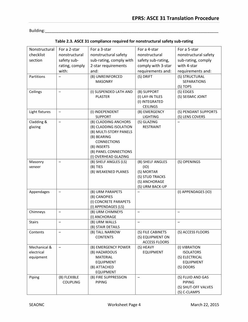
2.3 Nonstructural
Compare the ASCE 31 deficiency list with Table 2.3, and determine the highest nonstructural safety sub-
rating justified by the evaluation.
Notes:
• In Table 2.3, the initial (B), (I), or (S) indicates the ASCE 31 nonstructural checklist where the
item is found: Basic, Intermediate, or Supplemental.
• In Table 2.3, for purposes of deriving the Safety rating only, items in the 3-star and 4-star
columns need not be considered NC if the non-compliance occurs only in locations where
related damage would not cause severe injury or death. Findings from ASCE 31 evaluations
performed at the Life Safety level only might need to be revised for purposes of deriving Repair
Cost and Recovery ratings if the ASCE 31 findings assumed unoccupied spaces. Commentary:
This allowance is consistent with ASCE 41-13 Section 16.17.
EPRS: ASCE 31 Translation Procedure
Building:______________________________________________________________________________
SEAONC Worksheet Page 4 March 22, 2015
Table 2.3. ASCE 31 compliance required for nonstructural safety sub-rating
Nonstructural
checklist
section
For a 2-star
nonstructural
safety sub-
rating, comply
with:
For a 3-star
nonstructural safety
sub-rating, comply with
2-star requirements
and:
For a 4-star
nonstructural
safety sub-rating,
comply with 3-star
requirements and:
For a 5-star
nonstructural safety
sub-rating, comply
with 4-star
requirements and:
Partitions – (B) UNREINFORCED
MASONRY
(S) DRIFT (S) STRUCTURAL
SEPARATIONS
(S) TOPS
Ceilings – (I) SUSPENDED LATH AND
PLASTER
(B) SUPPORT
(I) LAY-IN TILES
(I) INTEGRATED
CEILINGS
(S) EDGES
(S) SEISMIC JOINT
Light fixtures – (I) INDEPENDENT
SUPPORT
(B) EMERGENCY
LIGHTING
(S) PENDANT SUPPORTS
(S) LENS COVERS
Cladding &
glazing
– (B) CLADDING ANCHORS
(B) CLADDING ISOLATION
(B) MULTI-STORY PANELS
(B) BEARING
CONNECTIONS
(B) INSERTS
(B) PANEL CONNECTIONS
(I) OVERHEAD GLAZING
(S) GLAZING
RESTRAINT
–
Masonry
veneer
– (B) SHELF ANGLES (LS)
(B) TIES
(B) WEAKENED PLANES
(B) SHELF ANGLES
(IO)
(S) MORTAR
(S) STUD TRACKS
(S) ANCHORAGE
(S) URM BACK-UP
(S) OPENINGS
Appendages – (B) URM PARAPETS
(B) CANOPIES
(I) CONCRETE PARAPETS
(I) APPENDAGES (LS)
– (I) APPENDAGES (IO)
Chimneys – (B) URM CHIMNEYS
(I) ANCHORAGE
– –
Stairs – (B) URM WALLS
(B) STAIR DETAILS
– –
Contents – (B) TALL NARROW
CONTENTS
(S) FILE CABINETS
(S) EQUIPMENT ON
ACCESS FLOORS
(S) ACCESS FLOORS
Mechanical &
electrical
equipment
– (B) EMERGENCY POWER
(B) HAZARDOUS
MATERIAL
EQUIPMENT
(B) ATTACHED
EQUIPMENT
(S) HEAVY
EQUIPMENT
(I) VIBRATION
ISOLATORS
(S) ELECTRICAL
EQUIPMENT
(S) DOORS
Piping (B) FLEXIBLE
COUPLING
(B) FIRE SUPPRESSION
PIPING
– (S) FLUID AND GAS
PIPING
(S) SHUT-OFF VALVES
(S) C-CLAMPS

EPRS: ASCE 31 Translation Procedure
Building:______________________________________________________________________________
SEAONC Worksheet Page 5 March 22, 2015
Nonstructural
checklist
section
For a 2-star
nonstructural
safety sub-
rating, comply
with:
For a 3-star
nonstructural safety
sub-rating, comply with
2-star requirements
and:
For a 4-star
nonstructural
safety sub-rating,
comply with 3-star
requirements and:
For a 5-star
nonstructural safety
sub-rating, comply
with 4-star
requirements and:
Ducts – (I) STAIR AND SMOKE
DUCTS
– (S) DUCT BRACING
(S) DUCT SUPPORT
Hazardous
materials
(S) GAS
CYLINDERS
(B) TOXIC SUBSTANCES
(S) HAZARDOUS
MATERIALS
– –
Elevators – – – (S) SUPPORT SYSTEM
(S) SEISMIC SWITCH
(S) SHAFT WALLS
(S) RETAINER GUARDS
(S) RETAINER PLATE
(S) COUNTERWEIGHT
RAILS
(S) BRACKETS
(S) SPREADER BRACKET
(S) GO-SLOW
ELEVATORS
2.4 Safety Rating Summary
Structural safety sub-rating from line 2.1: ______
Geologic/foundation safety sub-rating from line 2.2: ______
Nonstructural safety sub-rating from line 2.3: ______
The overall Safety Rating is the lowest of the three sub-ratings: ______
Part 3. Repair Cost Rating
Repair Cost Rating instructions and notes:
1. The Repair Cost Rating is taken as the lowest of two sub-ratings: Geologic, and
Structural/nonstructural.
3.1 Geologic
Are any of the following Tier 1 checklist items on the ASCE 31 deficiency list? ______
• LIQUEFACTION
• SLOPE FAILURE
• SURFACE FAULT RUPTURE
CHECK: If Yes, the geologic repair cost sub-rating is 1-star. If No, the geologic repair cost sub-rating is 5-
star.

EPRS: ASCE 31 Translation Procedure
Building:______________________________________________________________________________
SEAONC Worksheet Page 6 March 22, 2015
3.2 Structural/Nonstructural
Determine the structural/nonstructural repair cost sub-rating as a function of the ASCE 31 building type
and the overall building Safety Rating (line 2.4) from Table 3.2.
Note: Table 3.2 generally relies on the Safety rating, determined above. Where the nonstructural safety
sub-rating relies on assumptions that potential damage need not be considered NC because it would
occur in unoccupied areas or otherwise would not result in severe injury or death, such assumptions
must be set aside for purposes of deriving Repair Cost and Recovery ratings.
Table 3.2. Structural/nonstructural repair cost sub-rating as a function of ASCE 31
building type and overall Safety Rating
ASCE 31 building type
Safety Rating
5-star 4-star 3-star 2-star 1-star
W1, W1A, W2 4-star 3-star 3-star 2-star 1-star
Other 3-star 2-star 2-star 1-star 1-star
Commentary: Assignment of the structural/nonstructural repair cost sub-rating is intentionally
conservative. This reflects the understanding that ASCE 31 was not intended to predict costs. For more
discussion, see SEAONC EBC BRS (2012).
3.3 Repair Cost Rating summary
Geologic repair cost sub-rating from line 3.1: ______
Structural/nonstructural repair cost sub-rating from line 3.2: ______
The overall Repair Cost Rating is the lower of the two sub-ratings: ______

EPRS: ASCE 31 Translation Procedure
Building:______________________________________________________________________________
SEAONC Worksheet Page 7 March 22, 2015
Part 4. Recovery Rating
Recovery Rating instructions and notes:
1. The Recovery Rating is taken as the lowest of three sub-ratings: Geologic, Structural, and
Nonstructural.
Commentary: The EPRS Recovery Rating reflects functional recovery time, as opposed to the time needed
for either safe re-occupancy or for full recovery, but excludes the effects of externalities. See the EPRS
User’s Guide.
4.1 Geologic
Are any of the following Tier 1 checklist items on the ASCE 31 deficiency list? ______
• LIQUEFACTION
• SLOPE FAILURE
• SURFACE FAULT RUPTURE
CHECK: If Yes, the geologic recovery sub-rating is 1-star; skip to line 4.4 or, optionally, continue with line
4.2 or 4.3. If No, the geologic recovery sub-rating is 5-star.
4.2 Structural
Is the structural safety sub-rating (line 2.1) either 1-star or 2-star? _______
CHECK: If Yes, the structural recovery sub-rating is 1-star. Skip to line 4.4 or, optionally, continue with
line 4.3. If No, continue.
Is the structural safety sub-rating (line 2.1) either 3-star or 4-star? _______
CHECK: If Yes, the structural recovery sub-rating is 3-star. If No (that is, if the structural safety sub-rating
is 5-star), the structural recovery sub-rating is 5-star.
4.3 Nonstructural
4.3.1. Initial nonstructural recovery sub-rating:
Compare the ASCE 31 deficiency list with Table 4.3.1 and determine the highest nonstructural recovery
sub-rating justified by the evaluation.
Notes:
• In Table 4.3.1, the initial indicates the ASCE 31 nonstructural checklist where the item is found:
Basic (B), Intermediate (I), or Supplemental (S).
• Table 4.3.1 generally relies on the Safety rating, determined above. Where the nonstructural
safety sub-rating relies on assumptions that potential damage need not be considered NC
EPRS: ASCE 31 Translation Procedure
Building:______________________________________________________________________________
SEAONC Worksheet Page 8 March 22, 2015
because it would occur in unoccupied areas or otherwise would not result in severe injury or
death, such assumptions must be set aside for purposes of deriving Repair Cost and Recovery
ratings.
Commentary: Assignment of the nonstructural recovery sub-rating is based on SEAONC BRS judgment,
recognizing that ASCE 31 was not intended to predict recovery time. For more discussion, see SEAONC
EBC BRS (2012) and Bonowitz (2011) in the EPRS User’s Guide list of References.

EPRS: ASCE 31 Translation Procedure
Building:______________________________________________________________________________
SEAONC Worksheet Page 9 March 22, 2015
Table 4.3.1. ASCE 31 compliance required for nonstructural recovery sub-rating
Nonstructural
checklist
section
For a 2-star
nonstructural recovery
sub-rating, comply
with:
For a 3-star nonstructural
recovery sub-rating, comply
with 2-star requirements and:
For a 4-star nonstructural
recovery sub-rating, comply with
3-star requirements and:
For a 5-star nonstructural
recovery sub-rating, comply
with 4-star requirements and:
Partitions – – (B) UNREINFORCED MASONRY
(S) DRIFT
(S) TOPS
(S) STRUCTURAL SEPARATIONS
Ceilings – – (I) SUSPENDED LATH AND PLASTER
(B) SUPPORT
(I) INTEGRATED CEILINGS
(I) LAY-IN TILES
(S) EDGESa
(S) SEISMIC JOINTa
Light fixtures – (B) EMERGENCY LIGHTING
(I) INDEPENDENT SUPPORT
(S) PENDANT SUPPORTS
– (S) LENS COVERS
Cladding &
glazing
– – (B) CLADDING ANCHORS
(B) CLADDING ISOLATION
(B) MULTI-STORY PANELS
(B) BEARING CONNECTIONS
(B) INSERTS
(B) PANEL CONNECTIONS
(I) OVERHEAD GLAZING
(S) GLAZING RESTRAINT
–
Masonry
veneer
– – (B) SHELF ANGLES (LS)
(B) TIES
(B) WEAKENED PLANES
(S) MORTAR
(S) STUD TRACKS
(S) OPENINGS
(S) ANCHORAGE
(S) URM BACK-UP
–

EPRS: ASCE 31 Translation Procedure
Building:______________________________________________________________________________
SEAONC Worksheet Page 10 March 22, 2015
Nonstructural
checklist
section
For a 2-star
nonstructural recovery
sub-rating, comply
with:
For a 3-star nonstructural
recovery sub-rating, comply
with 2-star requirements and:
For a 4-star nonstructural
recovery sub-rating, comply with
3-star requirements and:
For a 5-star nonstructural
recovery sub-rating, comply
with 4-star requirements and:
Appendages – – (B) URM PARAPETS
(B) CANOPIES
(I) CONCRETE PARAPETS
(I) APPENDAGES (LS)
(I) APPENDAGES (IO)
–
Chimneys – – (B) URM CHIMNEYS
(I) ANCHORAGE
–
Stairs – (B) STAIR DETAILS (B) URM WALLS –
Contents – (S) ACCESS FLOORS
(S) EQUIPMENT ON ACCESS
FLOORS
– (B) TALL NARROW CONTENTS
(S) FILE CABINETSa
(S) CABINET DOORS AND
DRAWERSa
Mechanical &
electrical
equipment
– (B) EMERGENCY POWER
(B) HAZARDOUS MATERIAL
EQUIPMENT
(B) ATTACHED EQUIPMENT
(I) VIBRATION ISOLATORS
(S) ELECTRICAL EQUIPMENT
(S) DOORS
– (S) HEAVY EQUIPMENT
Piping (B) FIRE SUPPRESSION
PIPING
(B) FLEXIBLE COUPLING
(S) SHUT-OFF VALVES
(S) FLUID AND GAS
PIPING, hazmat
(S) FLUID PIPING, non hazmat (S) C-CLAMPS –
Ducts – (I) STAIR AND SMOKE DUCTS
(S) DUCT BRACING
(S) DUCT SUPPORT
– –

EPRS: ASCE 31 Translation Procedure
Building:______________________________________________________________________________
SEAONC Worksheet Page 11 March 22, 2015
Nonstructural
checklist
section
For a 2-star
nonstructural recovery
sub-rating, comply
with:
For a 3-star nonstructural
recovery sub-rating, comply
with 2-star requirements and:
For a 4-star nonstructural
recovery sub-rating, comply with
3-star requirements and:
For a 5-star nonstructural
recovery sub-rating, comply
with 4-star requirements and:
Hazardous
materials
(B) TOXIC SUBSTANCES
(S) GAS CYLINDERS
(S) HAZARDOUS
MATERIALS
– – –
Elevators – (S) SUPPORT SYSTEM
(S) SEISMIC SWITCH
(S) SHAFT WALLS
(S) RETAINER GUARDS
(S) RETAINER PLATE
(S) COUNTERWEIGHT RAILS
(S) BRACKETS
(S) SPREADER BRACKET
(S) GO-SLOW ELEVATORS
– –
a These items need not be considered except for purposes of adjusting the nonstructural recovery sub-rating in line 4.3.1.

EPRS: ASCE 31 Translation Procedure
Building:______________________________________________________________________________
SEAONC Worksheet Page 12 March 22, 2015
4.3.2. Adjusting the nonstructural recovery sub-rating:
The initial nonstructural recovery sub-rating based on Table 4.3.1 (line 4.3.1) is: ______.
If the initial sub-rating is 1-star, skip this line and proceed to line 4.4. Otherwise, in the following lines, at
the top of column (A), enter the initial nonstructural recovery sub-rating, plus 1 star. At the top of
column (B), enter the initial sub-rating plus 2 stars. (For example, if the initial sub-rating from line 4.3.1
is 3-star, enter 4-star at the top of column (A) and 5-star at the top of column (B).)
Complete column (A): Consider the items from the ASCE 31 deficiency list that appear in Table 4.3.1 in
the column corresponding to column A, and answer the following questions (Yes/No). (For example, if
column (A) is labeled 4-star, compare the deficiency list with the 4-star column of Table 4.3.1.) Complete
column (B) similarly.
(A)
___-star
(B)
___-star
4.3.2.1. Size adjustment: Are any of the deficiencies extensive throughout
the building, or is the building large enough that the functional
recovery time for that item would probably exceed the time implied
by the initial sub-rating?
4.3.2.2. Public use adjustment: Do any of the building’s occupancies or
functions of interest involve public access or accommodation, so
that the functional recovery time for any of the deficiencies must
consider issues of habitability or legal compliance?
4.3.2.3. Contents adjustment: Would any of the deficiencies (or expected
damage to other contents items not considered explicitly by ASCE
31) have a disproportionate impact on functional recovery time due
to specialized use or occupancy, or performance requirements of the
building?
Total number of Yes responses from lines 4.3.2.1 through 4.3.2.3:
The initial sub-rating, minus the total number of Yes responses in column (A) is: ____.
The initial sub-rating, plus 1, minus the total number of Yes responses in column (B) is: ____.
The final nonstructural recovery sub-rating is the lower of these two values: ____.
Commentary: The adjustment procedure reflects the following logic: First, consider the deficiencies that
are controlling the nonstructural recovery sub-rating; these will be in the Table 4.3.1 columns to the right
of the column with which the building complies. Then, ask if any of these deficiencies are extensive or
serious enough that they merit a lower sub-rating. If one condition applies, the sub-rating is reduced by
one star. If two or more apply, it is reduced by two stars.

EPRS: ASCE 31 Translation Procedure
Building:______________________________________________________________________________
SEAONC Worksheet Page 13 March 22, 2015
4.4 Recovery Rating summary
Geologic recovery sub-rating from line 4.1: ______
Structural recovery sub-rating from line 4.2: ______
Nonstructural recovery sub-rating from line 4.3.2: ______
The overall Recovery Rating is the lowest of the three sub-ratings: ______
Part 5. Summary
Record the three-part rating and the sub-ratings.
Sub-ratings Overall
rating
Rating to
report, or
No Rating Structural Geologic/
foundation
Nonstructural
Safety (line 2.4)
Repair Cost (line 3.3) Same as
structural
Recovery (line 4.4)
Commentary: The EPRS allows the rating engineer to report No Rating for any of the rating dimensions,
as discussed in the EPRS User’s Guide.
Tip: If unknown conditions are driving the rating, consider reporting the rating as “No Rating” as an
indication that more work might be justified to reach a more reliable conclusion.

Table 2.1 ASCE 31 Compliance Required for Structural Safety Sub-rating EPRS: ASCE 31 Translation Procedure
5-Star 4-Star 3-Star 2-Star
4.3.1.1 Basic Building System General LOAD PATH C C C C
4.3.2.4 Basic Building System Configuration VERTICAL DISCONTINUITIES C C C C
4.4.2.1.1 Basic Lateral Force Resisting System Shear Walls REDUNDANCY, shear walls C C C
4.4.2.7.1 Basic Lateral Force Resisting System Shear Walls SHEAR STRESS CHECK, wood walls C C C C
4.4.2.7.2 Basic Lateral Force Resisting System Shear Walls STUCCO (EXTERIOR PLASTER) SHEAR WALLS C C C C
4.4.2.7.3 Basic Lateral Force Resisting System Shear Walls GYPSUM WALLBOARD OR PLASTER SHEAR WALLS C C C C
4.4.2.7.4 Basic Lateral Force Resisting System Shear Walls NARROW WOOD SHEAR WALLS (LS) C C C
4.4.2.7.4 Basic Lateral Force Resisting System Shear Walls NARROW WOOD SHEAR WALLS (IO) C
4.4.2.7.5 Basic Lateral Force Resisting System Shear Walls WALLS CONNECTED THROUGH FLOORS C C C C
4.4.2.7.6 Basic Lateral Force Resisting System Shear Walls HILLSIDE SITE (LS) C C C C
4.4.2.7.6 Basic Lateral Force Resisting System Shear Walls HILLSIDE SITE (IO) C
4.4.2.7.7 Basic Lateral Force Resisting System Shear Walls CRIPPLE WALLS C C C
4.4.2.7.8 Basic Lateral Force Resisting System Shear Walls OPENINGS C C C C
4.6.3.3 Basic Connections Vertical Components WOOD POSTS C C C
4.6.3.4 Basic Connections Vertical Components WOOD SILLS C C C
4.6.4.1 Basic Connections Interconnection of Elements GIRDER/COLUMN CONNECTION C C C
4.4.2.7.9 Supplemental Lateral Force Resisting System Shear Walls HOLD-DOWN ANCHORS C
4.5.1.1 Supplemental Diaphragms General DIAPHRAGM CONTINUITY C C C C
4.5.1.2 Supplemental Diaphragms General DIAPHRAGM CONTINUITY (One Story Building) C C C
4.5.1.3 Supplemental Diaphragms General ROOF CHORD CONTINUITY C C C
4.5.1.7 Supplemental Diaphragms General PLAN IRREGULARITIES C
4.5.1.8 Supplemental Diaphragms General DIAPHRAGM REINFORCEMENT AT OPENINGS C
4.5.2.1 Supplemental Diaphragms Wood Diaphragms STRAIGHT SHEATHING (LS) C C C
4.5.2.1 Supplemental Diaphragms Wood Diaphragms STRAIGHT SHEATHING (IO) C
4.5.2.2 Supplemental Diaphragms Wood Diaphragms SPANS (LS) C C C
4.5.2.2 Supplemental Diaphragms Wood Diaphragms SPANS (IO) C
4.5.2.3 Supplemental Diaphragms Wood Diaphragms UNBLOCKED DIAPHRAGMS (LS) C C C
4.5.2.3 Supplemental Diaphragms Wood Diaphragms UNBLOCKED DIAPHRAGMS (IO) C
4.5.7.1 Supplemental Diaphragms Other Diaphragms OTHER DIAPHRAGMS C C C
4.6.3.9 Supplemental Connections Vertical Components WOOD SILL BOLTS (LS) C C C
4.6.3.9 Supplemental Connections Vertical Components WOOD SILL BOLTS (IO) C
Note: C = Compliance required for the safety sub-rating shown
ASCE 31
Tier 2
Section Checklist Heading Section Item C NC NA U
Compliance Required for
Safety sub-Rating:
Table 2.1 - W1 (Wood Light Frames)
SEAONC Worksheet Page 14 March 31, 2015

Table 2.1 ASCE 31 Compliance Required for Structural Safety Sub-rating EPRS: ASCE 31 Translation Procedure
5-Star 4-Star 3-Star 2-Star
4.3.1.1 Basic Building System General LOAD PATH C C C C
4.3.2.1 Basic Building System Configuration WEAK STORY C C C C
4.3.2.2 Basic Building System Configuration SOFT STORY C C C C
4.3.2.4 Basic Building System Configuration VERTICAL DISCONTINUITIES C C C C
4.4.2.1.1 Basic Lateral Force Resisting System Shear Walls REDUNDANCY, shear walls C C C
4.4.2.7.1 Basic Lateral Force Resisting System Shear Walls SHEAR STRESS CHECK, wood walls C C C C
4.4.2.7.2 Basic Lateral Force Resisting System Shear Walls STUCCO (EXTERIOR PLASTER) SHEAR WALLS C C C C
4.4.2.7.3 Basic Lateral Force Resisting System Shear Walls GYPSUM WALLBOARD OR PLASTER SHEAR WALLS C C C C
4.4.2.7.4 Basic Lateral Force Resisting System Shear Walls NARROW WOOD SHEAR WALLS (LS) C C C C
4.4.2.7.4 Basic Lateral Force Resisting System Shear Walls NARROW WOOD SHEAR WALLS (IO) C
4.4.2.7.5 Basic Lateral Force Resisting System Shear Walls WALLS CONNECTED THROUGH FLOORS C C C C
4.4.2.7.6 Basic Lateral Force Resisting System Shear Walls HILLSIDE SITE (LS) C C C C
4.4.2.7.6 Basic Lateral Force Resisting System Shear Walls HILLSIDE SITE (IO) C
4.4.2.7.7 Basic Lateral Force Resisting System Shear Walls CRIPPLE WALLS C C C C
4.4.2.7.8 Basic Lateral Force Resisting System Shear Walls OPENINGS C C C C
4.6.3.3 Basic Connections Vertical Components WOOD POSTS C C C
4.6.3.4 Basic Connections Vertical Components WOOD SILLS C C C C
4.6.4.1 Basic Connections Interconnection of Elements GIRDER/COLUMN CONNECTION C C C C
4.4.2.7.9 Supplemental Lateral Force Resisting System Shear Walls HOLD-DOWN ANCHORS C
4.5.1.1 Supplemental Diaphragms General DIAPHRAGM CONTINUITY C C C C
4.5.1.3 Supplemental Diaphragms General ROOF CHORD CONTINUITY C C C
4.5.1.7 Supplemental Diaphragms General PLAN IRREGULARITIES C
4.5.1.8 Supplemental Diaphragms General DIAPHRAGM REINFORCEMENT AT OPENINGS C
4.5.2.1 Supplemental Diaphragms Wood Diaphragms STRAIGHT SHEATHING (LS) C C C
4.5.2.1 Supplemental Diaphragms Wood Diaphragms STRAIGHT SHEATHING (IO) C
4.5.2.2 Supplemental Diaphragms Wood Diaphragms SPANS (LS) C C C
4.5.2.2 Supplemental Diaphragms Wood Diaphragms SPANS (IO) C
4.5.2.3 Supplemental Diaphragms Wood Diaphragms UNBLOCKED DIAPHRAGMS (LS) C C C
4.5.2.3 Supplemental Diaphragms Wood Diaphragms UNBLOCKED DIAPHRAGMS (IO) C
4.5.7.1 Supplemental Diaphragms Other Diaphragms OTHER DIAPHRAGMS C C C
4.6.3.9 Supplemental Connections Vertical Components WOOD SILL BOLTS (LS) C C C
4.6.3.9 Supplemental Connections Vertical Components WOOD SILL BOLTS (IO) C
Note: C = Compliance required for the safety sub-rating shown
ASCE 31
Tier 2
Section Checklist Heading Section Item C NC NA U
Compliance Required for
Safety sub-Rating:
Table 2.1 - W1A (Wood Multi-Story, Multi-Unit, Residential)
SEAONC Worksheet Page 15 March 31, 2015

Table 2.1 ASCE 31 Compliance Required for Structural Safety Sub-rating EPRS: ASCE 31 Translation Procedure
5-Star 4-Star 3-Star 2-Star
4.3.1.1 Basic Building System General LOAD PATH C C C C
4.3.1.3 Basic Building System General MEZZANINES C C C
4.3.2.1 Basic Building System Configuration WEAK STORY C C C C
4.3.2.2 Basic Building System Configuration SOFT STORY C C C C
4.3.2.3 Basic Building System Configuration GEOMETRY C C C C
4.3.2.4 Basic Building System Configuration VERTICAL DISCONTINUITIES C C C C
4.3.2.5 Basic Building System Configuration MASS C C C C
4.4.2.1.1 Basic Lateral Force Resisting System Shear Walls REDUNDANCY, shear walls C C C
4.4.2.7.1 Basic Lateral Force Resisting System Shear Walls SHEAR STRESS CHECK, wood walls C C C C
4.4.2.7.2 Basic Lateral Force Resisting System Shear Walls STUCCO (EXTERIOR PLASTER) SHEAR WALLS C C C C
4.4.2.7.3 Basic Lateral Force Resisting System Shear Walls GYPSUM WALLBOARD OR PLASTER SHEAR WALLS C C C C
4.4.2.7.4 Basic Lateral Force Resisting System Shear Walls NARROW WOOD SHEAR WALLS (LS) C C C C
4.4.2.7.4 Basic Lateral Force Resisting System Shear Walls NARROW WOOD SHEAR WALLS (IO) C
4.4.2.7.5 Basic Lateral Force Resisting System Shear Walls WALLS CONNECTED THROUGH FLOORS C C C C
4.4.2.7.6 Basic Lateral Force Resisting System Shear Walls HILLSIDE SITE (LS) C C C C
4.4.2.7.6 Basic Lateral Force Resisting System Shear Walls HILLSIDE SITE (IO) C
4.4.2.7.7 Basic Lateral Force Resisting System Shear Walls CRIPPLE WALLS C C C C
4.4.2.7.8 Basic Lateral Force Resisting System Shear Walls OPENINGS C C C C
4.6.3.3 Basic Connections Vertical Components WOOD POSTS C C C
4.6.3.4 Basic Connections Vertical Components WOOD SILLS C C C C
4.6.4.1 Basic Connections Interconnection of Elements GIRDER/COLUMN CONNECTION C C C C
4.4.2.7.9 Supplemental Lateral Force Resisting System Shear Walls HOLD-DOWN ANCHORS C
4.5.1.1 Supplemental Diaphragms General DIAPHRAGM CONTINUITY C C C C
4.5.1.3 Supplemental Diaphragms General ROOF CHORD CONTINUITY C C C
4.5.1.7 Supplemental Diaphragms General PLAN IRREGULARITIES C
4.5.1.8 Supplemental Diaphragms General DIAPHRAGM REINFORCEMENT AT OPENINGS C
4.5.2.1 Supplemental Diaphragms Wood Diaphragms STRAIGHT SHEATHING (LS) C C C
4.5.2.1 Supplemental Diaphragms Wood Diaphragms STRAIGHT SHEATHING (IO) C
4.5.2.2 Supplemental Diaphragms Wood Diaphragms SPANS (LS) C C C
4.5.2.2 Supplemental Diaphragms Wood Diaphragms SPANS (IO) C
4.5.2.3 Supplemental Diaphragms Wood Diaphragms UNBLOCKED DIAPHRAGMS (LS) C C C
4.5.2.3 Supplemental Diaphragms Wood Diaphragms UNBLOCKED DIAPHRAGMS (IO) C
4.5.7.1 Supplemental Diaphragms Other Diaphragms OTHER DIAPHRAGMS C C C
4.6.3.9 Supplemental Connections Vertical Components WOOD SILL BOLTS (LS) C C C
4.6.3.9 Supplemental Connections Vertical Components WOOD SILL BOLTS (IO) C
Note: C = Compliance required for the safety sub-rating shown
ASCE 31
Tier 2
Section Checklist Heading Section Item C NC NA U
Compliance Required for
Safety sub-Rating:
Table 2.1 - W2 (Wood Frames, Commercial & Industrial)
SEAONC Worksheet Page 16 March 31, 2015

Table 2.1 ASCE 31 Compliance Required for Structural Safety Sub-rating EPRS: ASCE 31 Translation Procedure
5-Star 4-Star 3-Star 2-Star
4.3.1.1 Basic Building System General LOAD PATH C C C C
4.3.1.2 Basic Building System General ADJACENT BUILDINGS C C C
4.3.1.3 Basic Building System General MEZZANINES C C C
4.3.2.1 Basic Building System Configuration WEAK STORY C C C C
4.3.2.2 Basic Building System Configuration SOFT STORY C C C C
4.3.2.3 Basic Building System Configuration GEOMETRY C C C C
4.3.2.4 Basic Building System Configuration VERTICAL DISCONTINUITIES C C C C
4.3.2.5 Basic Building System Configuration MASS C C C C
4.3.2.6 Basic Building System Configuration TORSION C C C C
4.4.1.1.1 Basic Lateral Force Resisting System Moment Frames REDUNDANCY, moment frames (LS) C C C
4.4.1.1.1 Basic Lateral Force Resisting System Moment Frames REDUNDANCY, moment frames (IO) C
4.4.1.2.1 Basic Lateral Force Resisting System Moment Frames INTERFERING WALLS C C C
4.4.1.3.1. Basic Lateral Force Resisting System Moment Frames DRIFT CHECK (LS) C C C
4.4.1.3.1. Basic Lateral Force Resisting System Moment Frames DRIFT CHECK (IO) C
4.4.1.3.2 Basic Lateral Force Resisting System Moment Frames AXIAL STRESS CHECK, steel columns C C C C
4.6.2.2 Basic Connections Shear Transfer TRANSFER TO STEEL FRAMES (LS) C C C C
4.6.2.2 Basic Connections Shear Transfer TRANSFER TO STEEL FRAMES (IO) C
4.6.3.1 Basic Connections Vertical Components STEEL COLUMNS (LS) C C C C
4.6.3.1 Basic Connections Vertical Components STEEL COLUMNS (IO) C
4.4.1.3.3 Supplemental Lateral Force Resisting System Moment Frames MOMENT-RESISTING CONNECTIONS C C C
4.4.1.3.4 Supplemental Lateral Force Resisting System Moment Frames PANEL ZONES C C C
4.4.1.3.5 Supplemental Lateral Force Resisting System Moment Frames COLUMN SPLICES, steel moment frames (LS) C C C C
4.4.1.3.5 Supplemental Lateral Force Resisting System Moment Frames COLUMN SPLICES, steel moment frames (IO) C
4.4.1.3.6 Supplemental Lateral Force Resisting System Moment Frames STRONG COLUMN/WEAK BEAM, steel C C C
4.4.1.3.7 Supplemental Lateral Force Resisting System Moment Frames COMPACT MEMBERS C C C
4.4.1.3.8 Supplemental Lateral Force Resisting System Moment Frames BEAM PENETRATIONS C
4.4.1.3.9 Supplemental Lateral Force Resisting System Moment Frames GIRDER FLANGE CONTINUITY PLATES C
4.4.1.3.10 Supplemental Lateral Force Resisting System Moment Frames OUT-OF-PLANE BRACING, steel moment frames C
4.4.1.3.11 Supplemental Lateral Force Resisting System Moment Frames BOTTOM FLANGE BRACING C
4.5.1.7 Supplemental Diaphragms General PLAN IRREGULARITIES C
4.5.1.8 Supplemental Diaphragms General DIAPHRAGM REINFORCEMENT AT OPENINGS C
4.6.3.10 Supplemental Connections Vertical Components UPLIFT AT PILE CAPS (LS) C C C
4.6.3.10 Supplemental Connections Vertical Components UPLIFT AT PILE CAPS (IO) C
Note: C = Compliance required for the safety sub-rating shown
ASCE 31
Tier 2
Section Checklist Heading Section Item C NC NA U
Compliance Required for
Safety sub-Rating:
Table 2.1 - S1 (Steel Moment Frames - Stiff Diaphragms)
SEAONC Worksheet Page 17 March 31, 2015

Table 2.1 ASCE 31 Compliance Required for Structural Safety Sub-rating EPRS: ASCE 31 Translation Procedure
5-Star 4-Star 3-Star 2-Star
4.3.1.1 Basic Building System General LOAD PATH C C C C
4.3.1.2 Basic Building System General ADJACENT BUILDINGS C C C
4.3.1.3 Basic Building System General MEZZANINES C C C
4.3.2.1 Basic Building System Configuration WEAK STORY C C C C
4.3.2.2 Basic Building System Configuration SOFT STORY C C C C
4.3.2.3 Basic Building System Configuration GEOMETRY C C C C
4.3.2.4 Basic Building System Configuration VERTICAL DISCONTINUITIES C C C C
4.3.2.5 Basic Building System Configuration MASS C C C C
4.4.1.1.1 Basic Lateral Force Resisting System Moment Frames REDUNDANCY, moment frames (LS) C C C
4.4.1.1.1 Basic Lateral Force Resisting System Moment Frames REDUNDANCY, moment frames (IO) C
4.4.1.2.1 Basic Lateral Force Resisting System Moment Frames INTERFERING WALLS C C C
4.4.1.3.1. Basic Lateral Force Resisting System Moment Frames DRIFT CHECK (LS) C C C
4.4.1.3.1. Basic Lateral Force Resisting System Moment Frames DRIFT CHECK (IO) C
4.4.1.3.2 Basic Lateral Force Resisting System Moment Frames AXIAL STRESS CHECK, steel columns C C C C
4.6.2.2 Basic Connections Shear Transfer TRANSFER TO STEEL FRAMES (LS) C C C C
4.6.2.2 Basic Connections Shear Transfer TRANSFER TO STEEL FRAMES (IO) C
4.6.3.1 Basic Connections Vertical Components STEEL COLUMNS (LS) C C C C
4.6.3.1 Basic Connections Vertical Components STEEL COLUMNS (IO) C
4.4.1.3.3 Supplemental Lateral Force Resisting System Moment Frames MOMENT-RESISTING CONNECTIONS C C C
4.4.1.3.4 Supplemental Lateral Force Resisting System Moment Frames PANEL ZONES C C C
4.4.1.3.5 Supplemental Lateral Force Resisting System Moment Frames COLUMN SPLICES, steel moment frames (LS) C C C C
4.4.1.3.5 Supplemental Lateral Force Resisting System Moment Frames COLUMN SPLICES, steel moment frames (IO) C
4.4.1.3.6 Supplemental Lateral Force Resisting System Moment Frames STRONG COLUMN/WEAK BEAM, steel C C C
4.4.1.3.7 Supplemental Lateral Force Resisting System Moment Frames COMPACT MEMBERS C C C
4.4.1.3.8 Supplemental Lateral Force Resisting System Moment Frames BEAM PENETRATIONS C
4.4.1.3.9 Supplemental Lateral Force Resisting System Moment Frames GIRDER FLANGE CONTINUITY PLATES C
4.4.1.3.10 Supplemental Lateral Force Resisting System Moment Frames OUT-OF-PLANE BRACING, steel moment frames C
4.4.1.3.11 Supplemental Lateral Force Resisting System Moment Frames BOTTOM FLANGE BRACING C
4.5.1.2 Supplemental Diaphragms General CROSS TIES C C C
4.5.1.7 Supplemental Diaphragms General PLAN IRREGULARITIES C
4.5.1.8 Supplemental Diaphragms General DIAPHRAGM REINFORCEMENT AT OPENINGS C
4.5.2.1 Supplemental Diaphragms Wood Diaphragms STRAIGHT SHEATHING (LS) C C C
4.5.2.1 Supplemental Diaphragms Wood Diaphragms STRAIGHT SHEATHING (IO) C
4.5.2.2 Supplemental Diaphragms Wood Diaphragms SPANS (LS) C C C
4.5.2.2 Supplemental Diaphragms Wood Diaphragms SPANS (IO) C
4.5.2.3 Supplemental Diaphragms Wood Diaphragms UNBLOCKED DIAPHRAGMS (LS) C C C
4.5.2.3 Supplemental Diaphragms Wood Diaphragms UNBLOCKED DIAPHRAGMS (IO) C
4.5.3.1 Supplemental Diaphragms Metal Deck Diaphragms NON-CONCRETE FILLED DIAPHRAGMS C
4.5.7.1 Supplemental Diaphragms Other Diaphragms OTHER DIAPHRAGMS C C C
4.6.3.10 Supplemental Connections Vertical Components UPLIFT AT PILE CAPS (LS) C C C
4.6.3.10 Supplemental Connections Vertical Components UPLIFT AT PILE CAPS (IO) C
Note: C = Compliance required for the safety sub-rating shown
ASCE 31
Tier 2
Section Checklist Heading Section Item C NC NA U
Compliance Required for
Safety sub-Rating:
Table 2.1 - S1A (Steel Moment Frames - Flexible Diaphragms)
SEAONC Worksheet Page 18 March 31, 2015
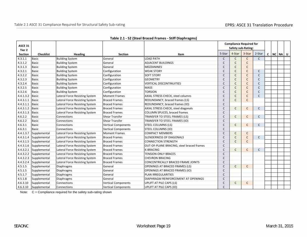
Table 2.1 ASCE 31 Compliance Required for Structural Safety Sub-rating EPRS: ASCE 31 Translation Procedure
5-Star 4-Star 3-Star 2-Star
4.3.1.1 Basic Building System General LOAD PATH C C C C
4.3.1.2 Basic Building System General ADJACENT BUILDINGS C C C
4.3.1.3 Basic Building System General MEZZANINES C C C
4.3.2.1 Basic Building System Configuration WEAK STORY C C C C
4.3.2.2 Basic Building System Configuration SOFT STORY C C C C
4.3.2.3 Basic Building System Configuration GEOMETRY C C C C
4.3.2.4 Basic Building System Configuration VERTICAL DISCONTINUITIES C C C C
4.3.2.5 Basic Building System Configuration MASS C C C C
4.3.2.6 Basic Building System Configuration TORSION C C C C
4.4.1.3.2 Basic Lateral Force Resisting System Moment Frames AXIAL STRESS CHECK, steel columns C C C C
4.4.3.1.1 Basic Lateral Force Resisting System Braced Frames REDUNDANCY, braced frames (LS) C C C
4.4.3.1.1 Basic Lateral Force Resisting System Braced Frames REDUNDANCY, braced frames (IO) C
4.4.3.1.2 Basic Lateral Force Resisting System Braced Frames AXIAL STRESS CHECK, steel diagonals C C C C
4.4.3.1.3 Basic Lateral Force Resisting System Braced Frames COLUMN SPLICES, braced frames C
4.6.2.2 Basic Connections Shear Transfer TRANSFER TO STEEL FRAMES (LS) C C C C
4.6.2.2 Basic Connections Shear Transfer TRANSFER TO STEEL FRAMES (IO) C
4.6.3.1 Basic Connections Vertical Components STEEL COLUMNS (LS) C C C C
4.6.3.1 Basic Connections Vertical Components STEEL COLUMNS (IO) C
4.4.1.3.7 Supplemental Lateral Force Resisting System Moment Frames COMPACT MEMBERS C C C
4.4.3.1.4 Supplemental Lateral Force Resisting System Braced Frames SLENDERNESS OF DIAGONALS C C C C
4.4.3.1.5 Supplemental Lateral Force Resisting System Braced Frames CONNECTION STRENGTH C C C
4.4.3.1.6 Supplemental Lateral Force Resisting System Braced Frames OUT-OF-PLANE BRACING, steel braced frames C
4.4.3.2.1 Supplemental Lateral Force Resisting System Braced Frames K-BRACING C C C C
4.4.3.2.2 Supplemental Lateral Force Resisting System Braced Frames TENSION-ONLY BRACES C
4.4.3.2.3 Supplemental Lateral Force Resisting System Braced Frames CHEVRON BRACING C
4.4.3.2.4 Supplemental Lateral Force Resisting System Braced Frames CONCENTRICALLY BRACED FRAME JOINTS C
4.5.1.5 Supplemental Diaphragms General OPENINGS AT BRACED FRAMES (LS) C C C
4.5.1.5 Supplemental Diaphragms General OPENINGS AT BRACED FRAMES (IO) C
4.5.1.7 Supplemental Diaphragms General PLAN IRREGULARITIES C
4.5.1.8 Supplemental Diaphragms General DIAPHRAGM REINFORCEMENT AT OPENINGS C
4.6.3.10 Supplemental Connections Vertical Components UPLIFT AT PILE CAPS (LS) C C C
4.6.3.10 Supplemental Connections Vertical Components UPLIFT AT PILE CAPS (IO) C
Note: C = Compliance required for the safety sub-rating shown
ASCE 31
Tier 2
Section Checklist Heading Section Item C NC NA U
Compliance Required for
Safety sub-Rating:
Table 2.1 - S2 (Steel Braced Frames - Stiff Diaphragms)
SEAONC Worksheet Page 19 March 31, 2015

Table 2.1 ASCE 31 Compliance Required for Structural Safety Sub-rating EPRS: ASCE 31 Translation Procedure
5-Star 4-Star 3-Star 2-Star
4.3.1.1 Basic Building System General LOAD PATH C C C C
4.3.1.2 Basic Building System General ADJACENT BUILDINGS C C C
4.3.1.3 Basic Building System General MEZZANINES C C C
4.3.2.1 Basic Building System Configuration WEAK STORY C C C C
4.3.2.2 Basic Building System Configuration SOFT STORY C C C C
4.3.2.3 Basic Building System Configuration GEOMETRY C C C C
4.3.2.4 Basic Building System Configuration VERTICAL DISCONTINUITIES C C C C
4.3.2.5 Basic Building System Configuration MASS C C C C
4.4.1.3.2 Basic Lateral Force Resisting System Moment Frames AXIAL STRESS CHECK, steel columns C C C C
4.4.3.1.1 Basic Lateral Force Resisting System Braced Frames REDUNDANCY, braced frames (LS) C C C
4.4.3.1.1 Basic Lateral Force Resisting System Braced Frames REDUNDANCY, braced frames (IO) C
4.4.3.1.2 Basic Lateral Force Resisting System Braced Frames AXIAL STRESS CHECK, steel diagonals C C C C
4.4.3.1.3 Basic Lateral Force Resisting System Braced Frames COLUMN SPLICES, braced frames C
4.6.2.2 Basic Connections Shear Transfer TRANSFER TO STEEL FRAMES (LS) C C C C
4.6.2.2 Basic Connections Shear Transfer TRANSFER TO STEEL FRAMES (IO) C
4.6.3.1 Basic Connections Vertical Components STEEL COLUMNS (LS) C C C C
4.6.3.1 Basic Connections Vertical Components STEEL COLUMNS (IO) C
4.4.1.3.7 Supplemental Lateral Force Resisting System Moment Frames COMPACT MEMBERS C C C
4.4.3.1.4 Supplemental Lateral Force Resisting System Braced Frames SLENDERNESS OF DIAGONALS C C C C
4.4.3.1.5 Supplemental Lateral Force Resisting System Braced Frames CONNECTION STRENGTH C C C
4.4.3.1.6 Supplemental Lateral Force Resisting System Braced Frames OUT-OF-PLANE BRACING, steel braced frames C
4.4.3.2.1 Supplemental Lateral Force Resisting System Braced Frames K-BRACING C C C C
4.4.3.2.2 Supplemental Lateral Force Resisting System Braced Frames TENSION-ONLY BRACES C
4.4.3.2.3 Supplemental Lateral Force Resisting System Braced Frames CHEVRON BRACING C
4.4.3.2.4 Supplemental Lateral Force Resisting System Braced Frames CONCENTRICALLY BRACED FRAME JOINTS C
4.5.1.2 Supplemental Diaphragms General CROSS TIES C C C
4.5.1.5 Supplemental Diaphragms General OPENINGS AT BRACED FRAMES (LS) C C C
4.5.1.5 Supplemental Diaphragms General OPENINGS AT BRACED FRAMES (IO) C
4.5.1.7 Supplemental Diaphragms General PLAN IRREGULARITIES C
4.5.1.8 Supplemental Diaphragms General DIAPHRAGM REINFORCEMENT AT OPENINGS C
4.5.2.1 Supplemental Diaphragms Wood Diaphragms STRAIGHT SHEATHING (LS) C C C
4.5.2.1 Supplemental Diaphragms Wood Diaphragms STRAIGHT SHEATHING (IO) C
4.5.2.2 Supplemental Diaphragms Wood Diaphragms SPANS (LS) C C C
4.5.2.2 Supplemental Diaphragms Wood Diaphragms SPANS (IO) C
4.5.2.3 Supplemental Diaphragms Wood Diaphragms UNBLOCKED DIAPHRAGMS (LS) C C C
4.5.2.3 Supplemental Diaphragms Wood Diaphragms UNBLOCKED DIAPHRAGMS (IO) C
4.5.3.1 Supplemental Diaphragms Metal Deck Diaphragms NON-CONCRETE FILLED DIAPHRAGMS C
4.6.3.10 Supplemental Connections Vertical Components UPLIFT AT PILE CAPS (LS) C C C
4.6.3.10 Supplemental Connections Vertical Components UPLIFT AT PILE CAPS (IO) C
Note: C = Compliance required for the safety sub-rating shown
ASCE 31
Tier 2
Section Checklist Heading Section Item C NC NA U
Compliance Required for
Safety sub-Rating:
Table 2.1 - S2A (Steel Braced Frames - Flexible Diaphragms)
SEAONC Worksheet Page 20 March 31, 2015

Table 2.1 ASCE 31 Compliance Required for Structural Safety Sub-rating EPRS: ASCE 31 Translation Procedure
5-Star 4-Star 3-Star 2-Star
4.3.1.1 Basic Building System General LOAD PATH C C C C
4.3.1.3 Basic Building System General MEZZANINES C C C
4.3.2.4 Basic Building System Configuration VERTICAL DISCONTINUITIES C C C C
4.3.2.6 Basic Building System Configuration TORSION C C C C
4.4.3.1.2 Basic Lateral Force Resisting System Braced Frames AXIAL STRESS CHECK, steel diagonals C C C C
4.6.2.2 Basic Connections Shear Transfer TRANSFER TO STEEL FRAMES (LS) C C C C
4.6.2.2 Basic Connections Shear Transfer TRANSFER TO STEEL FRAMES (IO) C
4.6.3.1 Basic Connections Vertical Components STEEL COLUMNS (LS) C C C C
4.6.3.1 Basic Connections Vertical Components STEEL COLUMNS (IO) C
4.6.3.8 Basic Connections Vertical Components WALL PANELS, foundation attachment C C C C
4.6.5.1 Basic Connections Panel Connections ROOF PANELS C C C
4.6.5.2 Basic Connections Panel Connections WALL PANELS, framing attachment C C C C
4.4.1.3.3 Supplemental Lateral Force Resisting System Moment Frames MOMENT-RESISTING CONNECTIONS C C C
4.4.1.3.7 Supplemental Lateral Force Resisting System Moment Frames COMPACT MEMBERS C C C
4.4.1.3.8 Supplemental Lateral Force Resisting System Moment Frames BEAM PENETRATIONS C
4.4.1.3.10 Supplemental Lateral Force Resisting System Moment Frames OUT-OF-PLANE BRACING, steel moment frames C
4.4.1.3.11 Supplemental Lateral Force Resisting System Moment Frames BOTTOM FLANGE BRACING C
4.5.1.7 Supplemental Diaphragms General PLAN IRREGULARITIES C
4.5.1.8 Supplemental Diaphragms General DIAPHRAGM REINFORCEMENT AT OPENINGS C
4.5.7.1 Supplemental Diaphragms Other Diaphragms OTHER DIAPHRAGMS C C C
4.6.3.10 Supplemental Connections Vertical Components UPLIFT AT PILE CAPS (LS) C C C
4.6.3.10 Supplemental Connections Vertical Components UPLIFT AT PILE CAPS (IO) C
Note: C = Compliance required for the safety sub-rating shown
ASCE 31
Tier 2
Section Checklist Heading Section Item C NC NA U
Compliance Required for
Safety sub-Rating:
Table 2.1 - S3 (Steel Light Frames)
SEAONC Worksheet Page 21 March 31, 2015

Table 2.1 ASCE 31 Compliance Required for Structural Safety Sub-rating EPRS: ASCE 31 Translation Procedure
5-Star 4-Star 3-Star 2-Star
4.3.1.1 Basic Building System General LOAD PATH C C C C
4.3.1.3 Basic Building System General MEZZANINES C C C
4.3.2.1 Basic Building System Configuration WEAK STORY C C C C
4.3.2.2 Basic Building System Configuration SOFT STORY C C C C
4.3.2.3 Basic Building System Configuration GEOMETRY C C C C
4.3.2.4 Basic Building System Configuration VERTICAL DISCONTINUITIES C C C C
4.3.2.5 Basic Building System Configuration MASS C C C C
4.3.2.6 Basic Building System Configuration TORSION C C C C
4.4.1.6.1 Basic Lateral Force Resisting System Moment Frames COMPLETE FRAMES C C C
4.4.2.1.1 Basic Lateral Force Resisting System Shear Walls REDUNDANCY, shear walls C C C
4.4.2.2.1 Basic Lateral Force Resisting System Shear Walls SHEAR STRESS CHECK, concrete walls C C C
4.4.2.2.2 Basic Lateral Force Resisting System Shear Walls REINFORCING STEEL, non-tilt-up concrete walls C C C
4.4.2.2.9 Basic Lateral Force Resisting System Shear Walls COLUMN SPLICES, encased steel columns C
4.6.2.1 Basic Connections Shear Transfer TRANSFER TO SHEAR WALLS (LS) C C C C
4.6.2.1 Basic Connections Shear Transfer TRANSFER TO SHEAR WALLS (IO) C
4.6.3.5 Basic Connections Vertical Components FOUNDATION DOWELS (LS) C C C C
4.6.3.5 Basic Connections Vertical Components FOUNDATION DOWELS (IO) C
4.6.3.6 Basic Connections Vertical Components SHEAR-WALL-BOUNDARY COLUMNS (LS) C C C C
4.6.3.6 Basic Connections Vertical Components SHEAR-WALL-BOUNDARY COLUMNS (IO) C
4.4.2.2.3 Supplemental Lateral Force Resisting System Shear Walls COUPLING BEAMS (LS) C C C
4.4.2.2.3 Supplemental Lateral Force Resisting System Shear Walls COUPLING BEAMS (IO) C
4.4.2.2.4 Supplemental Lateral Force Resisting System Shear Walls OVERTURNING, concrete shear walls C
4.4.2.2.5 Supplemental Lateral Force Resisting System Shear Walls CONFINEMENT REINFORCING C
4.4.2.2.6 Supplemental Lateral Force Resisting System Shear Walls REINFORCING AT OPENINGS, concrete walls C
4.4.2.2.7 Supplemental Lateral Force Resisting System Shear Walls WALL THICKNESS, cast-in-place concrete C
4.4.2.2.8 Supplemental Lateral Force Resisting System Shear Walls WALL CONNECTIONS, concrete walls (LS) C C C
4.4.2.2.8 Supplemental Lateral Force Resisting System Shear Walls WALL CONNECTIONS, concrete walls (IO) C
4.5.1.4 Supplemental Diaphragms General OPENINGS AT SHEAR WALLS (LS) C C C
4.5.1.4 Supplemental Diaphragms General OPENINGS AT SHEAR WALLS (IO) C
4.5.1.7 Supplemental Diaphragms General PLAN IRREGULARITIES C
4.5.1.8 Supplemental Diaphragms General DIAPHRAGM REINFORCEMENT AT OPENINGS C
4.6.3.10 Supplemental Connections Vertical Components UPLIFT AT PILE CAPS (LS) C C C
4.6.3.10 Supplemental Connections Vertical Components UPLIFT AT PILE CAPS (IO) C
Note: C = Compliance required for the safety sub-rating shown
ASCE 31
Tier 2
Section Checklist Heading Section Item C NC NA U
Compliance Required for
Safety sub-Rating:
Table 2.1 - S4 (Steel Frames with Concrete Shearwalls)
SEAONC Worksheet Page 22 March 31, 2015

Table 2.1 ASCE 31 Compliance Required for Structural Safety Sub-rating EPRS: ASCE 31 Translation Procedure
5-Star 4-Star 3-Star 2-Star
4.3.1.1 Basic Building System General LOAD PATH C C C C
4.3.1.3 Basic Building System General MEZZANINES C C C
4.3.2.1 Basic Building System Configuration WEAK STORY C C C C
4.3.2.2 Basic Building System Configuration SOFT STORY C C C C
4.3.2.3 Basic Building System Configuration GEOMETRY C C C C
4.3.2.4 Basic Building System Configuration VERTICAL DISCONTINUITIES C C C C
4.3.2.5 Basic Building System Configuration MASS C C C C
4.3.2.6 Basic Building System Configuration TORSION C C C C
4.4.2.1.1 Basic Lateral Force Resisting System Shear Walls REDUNDANCY, shear walls C C C
4.4.2.4.1 Basic Lateral Force Resisting System Shear Walls SHEAR STRESS CHECK, reinforced masonry walls C C C
4.4.2.5.1 Basic Lateral Force Resisting System Shear Walls SHEAR STRESS CHECK, URM walls C C C
4.4.2.6.1 Basic Lateral Force Resisting System Shear Walls WALL CONNECTIONS, masonry walls C C C C
4.6.2.1 Basic Connections Shear Transfer TRANSFER TO SHEAR WALLS (LS) C C C C
4.6.2.1 Basic Connections Shear Transfer TRANSFER TO SHEAR WALLS (IO) C
4.6.3.1 Basic Connections Vertical Components STEEL COLUMNS (LS) C C C C
4.6.3.1 Basic Connections Vertical Components STEEL COLUMNS (IO) C
4.4.2.4.3 Supplemental Lateral Force Resisting System Shear Walls REINFORCING AT OPENINGS, masonry walls C
4.4.2.6.2 Supplemental Lateral Force Resisting System Shear Walls PROPORTIONS, infill walls (LS) C C C
4.4.2.6.2 Supplemental Lateral Force Resisting System Shear Walls PROPORTIONS, infill walls (IO) C
4.4.2.6.3 Supplemental Lateral Force Resisting System Shear Walls SOLID WALLS C C C C
4.5.1.7 Supplemental Diaphragms General PLAN IRREGULARITIES C
4.5.1.8 Supplemental Diaphragms General DIAPHRAGM REINFORCEMENT AT OPENINGS C
4.6.3.10 Supplemental Connections Vertical Components UPLIFT AT PILE CAPS (LS) C C C
4.6.3.10 Supplemental Connections Vertical Components UPLIFT AT PILE CAPS (IO) C
Note: C = Compliance required for the safety sub-rating shown
ASCE 31
Tier 2
Section Checklist Heading Section Item C NC NA U
Compliance Required for
Safety sub-Rating:
Table 2.1 - S5 (Steel Frames with Infill Masonry Shearwalls)
SEAONC Worksheet Page 23 March 31, 2015

Table 2.1 ASCE 31 Compliance Required for Structural Safety Sub-rating EPRS: ASCE 31 Translation Procedure
5-Star 4-Star 3-Star 2-Star
4.3.1.1 Basic Building System General LOAD PATH C C C C
4.3.1.2 Basic Building System General ADJACENT BUILDINGS C C C
4.3.1.3 Basic Building System General MEZZANINES C C C
4.3.2.1 Basic Building System Configuration WEAK STORY C C C C
4.3.2.2 Basic Building System Configuration SOFT STORY C C C C
4.3.2.3 Basic Building System Configuration GEOMETRY C C C C
4.3.2.4 Basic Building System Configuration VERTICAL DISCONTINUITIES C C C C
4.3.2.5 Basic Building System Configuration MASS C C C C
4.4.2.1.1 Basic Lateral Force Resisting System Shear Walls REDUNDANCY, shear walls C C C
4.4.2.4.1 Basic Lateral Force Resisting System Shear Walls SHEAR STRESS CHECK, reinforced masonry walls C C C
4.4.2.5.1 Basic Lateral Force Resisting System Shear Walls SHEAR STRESS CHECK, URM walls C C C
4.4.2.6.1 Basic Lateral Force Resisting System Shear Walls WALL CONNECTIONS, masonry walls C C C C
4.6.2.1 Basic Connections Shear Transfer TRANSFER TO SHEAR WALLS (LS) C C C C
4.6.2.1 Basic Connections Shear Transfer TRANSFER TO SHEAR WALLS (IO) C
4.6.3.1 Basic Connections Vertical Components STEEL COLUMNS (LS) C C C C
4.6.3.1 Basic Connections Vertical Components STEEL COLUMNS (IO) C
4.4.2.4.3 Supplemental Lateral Force Resisting System Shear Walls REINFORCING AT OPENINGS, masonry walls C
4.4.2.6.2 Supplemental Lateral Force Resisting System Shear Walls PROPORTIONS, infill walls (LS) C C C
4.4.2.6.2 Supplemental Lateral Force Resisting System Shear Walls PROPORTIONS, infill walls (IO) C
4.4.2.6.3 Supplemental Lateral Force Resisting System Shear Walls SOLID WALLS C C C C
4.5.1.2 Supplemental Diaphragms General CROSS TIES C C C
4.5.1.7 Supplemental Diaphragms General PLAN IRREGULARITIES C
4.5.1.8 Supplemental Diaphragms General DIAPHRAGM REINFORCEMENT AT OPENINGS C
4.5.2.1 Supplemental Diaphragms Wood Diaphragms STRAIGHT SHEATHING (LS) C C C C
4.5.2.1 Supplemental Diaphragms Wood Diaphragms STRAIGHT SHEATHING (IO) C
4.5.2.2 Supplemental Diaphragms Wood Diaphragms SPANS (LS) C C C C
4.5.2.2 Supplemental Diaphragms Wood Diaphragms SPANS (IO) C
4.5.2.3 Supplemental Diaphragms Wood Diaphragms UNBLOCKED DIAPHRAGMS (LS) C C C C
4.5.2.3 Supplemental Diaphragms Wood Diaphragms UNBLOCKED DIAPHRAGMS (IO) C
4.5.3.1 Supplemental Diaphragms Metal Deck Diaphragms NON-CONCRETE FILLED DIAPHRAGMS C
4.5.7.1 Supplemental Diaphragms Other Diaphragms OTHER DIAPHRAGMS C C C
4.6.1.4 Supplemental Connections Anchorage for Normal Forces STIFFNESS OF WALL ANCHORS C C C
4.6.3.10 Supplemental Connections Vertical Components UPLIFT AT PILE CAPS (LS) C C C
4.6.3.10 Supplemental Connections Vertical Components UPLIFT AT PILE CAPS (IO) C
Note: C = Compliance required for the safety sub-rating shown
ASCE 31
Tier 2
Section Checklist Heading Section Item C NC NA U
Compliance Required for
Safety sub-Rating:
Table 2.1 - S5A (Steel Frames with Infill Masonry Shearwalls - Flexible Diaphragms)
SEAONC Worksheet Page 24 March 31, 2015

Table 2.1 ASCE 31 Compliance Required for Structural Safety Sub-rating EPRS: ASCE 31 Translation Procedure
5-Star 4-Star 3-Star 2-Star
4.3.1.1 Basic Building System General LOAD PATH C C C C
4.3.1.2 Basic Building System General ADJACENT BUILDINGS C C C
4.3.1.3 Basic Building System General MEZZANINES C C C
4.3.2.1 Basic Building System Configuration WEAK STORY C C C C
4.3.2.2 Basic Building System Configuration SOFT STORY C C C C
4.3.2.3 Basic Building System Configuration GEOMETRY C C C C
4.3.2.4 Basic Building System Configuration VERTICAL DISCONTINUITIES C C C C
4.3.2.5 Basic Building System Configuration MASS C C C C
4.3.2.6 Basic Building System Configuration TORSION C C C C
4.3.3.5 Basic Building System Condition of Materials POST-TENSIONING ANCHORS C C C
4.4.1.1.1 Basic Lateral Force Resisting System Moment Frames REDUNDANCY, moment frames (LS) C C C
4.4.1.1.1 Basic Lateral Force Resisting System Moment Frames REDUNDANCY, moment frames (IO) C
4.4.1.2.1 Basic Lateral Force Resisting System Moment Frames INTERFERING WALLS C C C C
4.4.1.4.1 Basic Lateral Force Resisting System Moment Frames SHEAR STRESS CHECK, concrete columns C C C C
4.4.1.4.2 Basic Lateral Force Resisting System Moment Frames AXIAL STRESS CHECK, concrete columns C C C C
4.6.3.2 Basic Connections Vertical Components CONCRETE COLUMNS (LS) C C C C
4.6.3.2 Basic Connections Vertical Components CONCRETE COLUMNS (IO) C
4.4.1.4.3 Supplemental Lateral Force Resisting System Moment Frames FLAT SLAB FRAMES C C C C
4.4.1.4.4 Supplemental Lateral Force Resisting System Moment Frames PRESTRESSED FRAME ELEMENTS C C C
4.4.1.4.5 Supplemental Lateral Force Resisting System Moment Frames CAPTIVE COLUMNS (LS) C C C C
4.4.1.4.5 Supplemental Lateral Force Resisting System Moment Frames CAPTIVE COLUMNS (IO) C
4.4.1.4.6 Supplemental Lateral Force Resisting System Moment Frames NO SHEAR FAILURES C C C C
4.4.1.4.7 Supplemental Lateral Force Resisting System Moment Frames STRONG COLUMN/WEAK BEAM, concrete C C C C
4.4.1.4.8 Supplemental Lateral Force Resisting System Moment Frames BEAM BARS C C C C
4.4.1.4.9 Supplemental Lateral Force Resisting System Moment Frames COLUMN-BAR SPLICES (LS) C C C C
4.4.1.4.9 Supplemental Lateral Force Resisting System Moment Frames COLUMN-BAR SPLICES (IO) C
4.4.1.4.10 Supplemental Lateral Force Resisting System Moment Frames BEAM BAR SPLICES C C C C
4.4.1.4.11 Supplemental Lateral Force Resisting System Moment Frames COLUMN-TIE SPACING C C C C
4.4.1.4.12 Supplemental Lateral Force Resisting System Moment Frames STIRRUP SPACING C C C C
4.4.1.4.13 Supplemental Lateral Force Resisting System Moment Frames JOINT REINFORCING C C C C
4.4.1.4.14 Supplemental Lateral Force Resisting System Moment Frames JOINT ECCENTRICITY C C C
4.4.1.4.15 Supplemental Lateral Force Resisting System Moment Frames STIRRUP AND TIE HOOKS C C C
4.4.1.6.2 Supplemental Lateral Force Resisting System Moment Frames DEFLECTION COMPATIBILITY (LS) C C C C
4.4.1.6.2 Supplemental Lateral Force Resisting System Moment Frames DEFLECTION COMPATIBILITY (IO) C
4.4.1.6.3 Supplemental Lateral Force Resisting System Moment Frames FLAT SLABS C C C C
4.5.1.1 Supplemental Diaphragms General DIAPHRAGM CONTINUITY C C C C
4.5.1.7 Supplemental Diaphragms General PLAN IRREGULARITIES C
4.5.1.8 Supplemental Diaphragms General DIAPHRAGM REINFORCEMENT AT OPENINGS C
4.6.3.10 Supplemental Connections Vertical Components UPLIFT AT PILE CAPS (LS) C C C
4.6.3.10 Supplemental Connections Vertical Components UPLIFT AT PILE CAPS (IO) C
Note: C = Compliance required for the safety sub-rating shown
ASCE 31
Tier 2
Section Checklist Heading Section Item C NC NA U
Compliance Required for
Safety sub-Rating:
Table 2.1 - C1 (Concrete Moment Frames)
SEAONC Worksheet Page 25 March 31, 2015
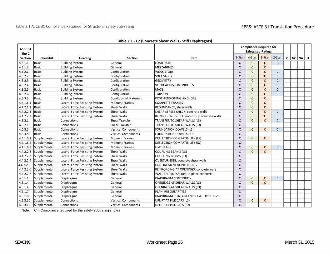
Table 2.1 ASCE 31 Compliance Required for Structural Safety Sub-rating EPRS: ASCE 31 Translation Procedure
5-Star 4-Star 3-Star 2-Star
4.3.1.1 Basic Building System General LOAD PATH C C C C
4.3.1.3 Basic Building System General MEZZANINES C C C
4.3.2.1 Basic Building System Configuration WEAK STORY C C C C
4.3.2.2 Basic Building System Configuration SOFT STORY C C C C
4.3.2.3 Basic Building System Configuration GEOMETRY C C C C
4.3.2.4 Basic Building System Configuration VERTICAL DISCONTINUITIES C C C C
4.3.2.5 Basic Building System Configuration MASS C C C C
4.3.2.6 Basic Building System Configuration TORSION C C C C
4.3.3.5 Basic Building System Condition of Materials POST-TENSIONING ANCHORS C C C
4.4.1.6.1 Basic Lateral Force Resisting System Moment Frames COMPLETE FRAMES C C C
4.4.2.1.1 Basic Lateral Force Resisting System Shear Walls REDUNDANCY, shear walls C C C
4.4.2.2.1 Basic Lateral Force Resisting System Shear Walls SHEAR STRESS CHECK, concrete walls C C C C
4.4.2.2.2 Basic Lateral Force Resisting System Shear Walls REINFORCING STEEL, non-tilt-up concrete walls C C C C
4.6.2.1 Basic Connections Shear Transfer TRANSFER TO SHEAR WALLS (LS) C C C C
4.6.2.1 Basic Connections Shear Transfer TRANSFER TO SHEAR WALLS (IO) C
4.6.3.5 Basic Connections Vertical Components FOUNDATION DOWELS (LS) C C C C
4.6.3.5 Basic Connections Vertical Components FOUNDATION DOWELS (IO) C
4.4.1.6.2 Supplemental Lateral Force Resisting System Moment Frames DEFLECTION COMPATIBILITY (LS) C C C
4.4.1.6.2 Supplemental Lateral Force Resisting System Moment Frames DEFLECTION COMPATIBILITY (IO) C
4.4.1.6.3 Supplemental Lateral Force Resisting System Moment Frames FLAT SLABS C C C C
4.4.2.2.3 Supplemental Lateral Force Resisting System Shear Walls COUPLING BEAMS (LS) C C C
4.4.2.2.3 Supplemental Lateral Force Resisting System Shear Walls COUPLING BEAMS (IO) C
4.4.2.2.4 Supplemental Lateral Force Resisting System Shear Walls OVERTURNING, concrete shear walls C
4.4.2.2.5 Supplemental Lateral Force Resisting System Shear Walls CONFINEMENT REINFORCING C
4.4.2.2.6 Supplemental Lateral Force Resisting System Shear Walls REINFORCING AT OPENINGS, concrete walls C
4.4.2.2.7 Supplemental Lateral Force Resisting System Shear Walls WALL THICKNESS, cast-in-place concrete C
4.5.1.1 Supplemental Diaphragms General DIAPHRAGM CONTINUITY C C C C
4.5.1.4 Supplemental Diaphragms General OPENINGS AT SHEAR WALLS (LS) C C C
4.5.1.4 Supplemental Diaphragms General OPENINGS AT SHEAR WALLS (IO) C
4.5.1.7 Supplemental Diaphragms General PLAN IRREGULARITIES C
4.5.1.8 Supplemental Diaphragms General DIAPHRAGM REINFORCEMENT AT OPENINGS C
4.6.3.10 Supplemental Connections Vertical Components UPLIFT AT PILE CAPS (LS) C C C
4.6.3.10 Supplemental Connections Vertical Components UPLIFT AT PILE CAPS (IO) C
Note: C = Compliance required for the safety sub-rating shown
ASCE 31
Tier 2
Section Checklist Heading Section Item C NC NA U
Compliance Required for
Safety sub-Rating:
Table 2.1 - C2 (Concrete Shear Walls - Stiff Diaphragms)
SEAONC Worksheet Page 26 March 31, 2015

Table 2.1 ASCE 31 Compliance Required for Structural Safety Sub-rating EPRS: ASCE 31 Translation Procedure
5-Star 4-Star 3-Star 2-Star
4.3.1.1 Basic Building System General LOAD PATH C C C C
4.3.1.2 Basic Building System General ADJACENT BUILDINGS C C C
4.3.1.3 Basic Building System General MEZZANINES C C C
4.3.2.1 Basic Building System Configuration WEAK STORY C C C C
4.3.2.2 Basic Building System Configuration SOFT STORY C C C C
4.3.2.3 Basic Building System Configuration GEOMETRY C C C C
4.3.2.4 Basic Building System Configuration VERTICAL DISCONTINUITIES C C C C
4.3.2.5 Basic Building System Configuration MASS C C C C
4.3.3.5 Basic Building System Condition of Materials POST-TENSIONING ANCHORS C C C
4.4.2.1.1 Basic Lateral Force Resisting System Shear Walls REDUNDANCY, shear walls C C C
4.4.2.2.1 Basic Lateral Force Resisting System Shear Walls SHEAR STRESS CHECK, concrete walls C C C C
4.4.2.2.2 Basic Lateral Force Resisting System Shear Walls REINFORCING STEEL, non-tilt-up concrete walls C C C C
4.6.1.1 Basic Connections Anchorage for Normal Forces WALL ANCHORAGE C C C C
4.6.2.1 Basic Connections Shear Transfer TRANSFER TO SHEAR WALLS (LS) C C C C
4.6.2.1 Basic Connections Shear Transfer TRANSFER TO SHEAR WALLS (IO) C
4.6.3.5 Basic Connections Vertical Components FOUNDATION DOWELS (LS) C C C C
4.6.3.5 Basic Connections Vertical Components FOUNDATION DOWELS (IO) C
4.4.2.2.3 Supplemental Lateral Force Resisting System Shear Walls COUPLING BEAMS (LS) C C C
4.4.2.2.3 Supplemental Lateral Force Resisting System Shear Walls COUPLING BEAMS (IO) C
4.4.2.2.4 Supplemental Lateral Force Resisting System Shear Walls OVERTURNING, concrete shear walls C
4.4.2.2.5 Supplemental Lateral Force Resisting System Shear Walls CONFINEMENT REINFORCING C
4.4.2.2.6 Supplemental Lateral Force Resisting System Shear Walls REINFORCING AT OPENINGS, concrete walls C
4.4.2.2.7 Supplemental Lateral Force Resisting System Shear Walls WALL THICKNESS, cast-in-place concrete C
4.5.1.1 Supplemental Diaphragms General DIAPHRAGM CONTINUITY C C C C
4.5.1.2 Supplemental Diaphragms General CROSS TIES C C C C
4.5.1.4 Supplemental Diaphragms General OPENINGS AT SHEAR WALLS (LS) C C C
4.5.1.4 Supplemental Diaphragms General OPENINGS AT SHEAR WALLS (IO) C
4.5.1.7 Supplemental Diaphragms General PLAN IRREGULARITIES C
4.5.1.8 Supplemental Diaphragms General DIAPHRAGM REINFORCEMENT AT OPENINGS C
4.5.2.1 Supplemental Diaphragms Wood Diaphragms STRAIGHT SHEATHING (LS) C C C C
4.5.2.1 Supplemental Diaphragms Wood Diaphragms STRAIGHT SHEATHING (IO) C
4.5.2.2 Supplemental Diaphragms Wood Diaphragms SPANS (LS) C C C C
4.5.2.2 Supplemental Diaphragms Wood Diaphragms SPANS (IO) C
4.5.2.3 Supplemental Diaphragms Wood Diaphragms UNBLOCKED DIAPHRAGMS (LS) C C C C
4.5.2.3 Supplemental Diaphragms Wood Diaphragms UNBLOCKED DIAPHRAGMS (IO) C
4.5.3.1 Supplemental Diaphragms Metal Deck Diaphragms NON-CONCRETE FILLED DIAPHRAGMS C
4.5.7.1 Supplemental Diaphragms Other Diaphragms OTHER DIAPHRAGMS C C C C
4.6.3.10 Supplemental Connections Vertical Components UPLIFT AT PILE CAPS (LS) C C C
4.6.3.10 Supplemental Connections Vertical Components UPLIFT AT PILE CAPS (IO) C
Note: C = Compliance required for the safety sub-rating shown
ASCE 31
Tier 2
Section Checklist Heading Section Item C NC NA U
Compliance Required for
Safety sub-Rating:
Table 2.1 - C2A (Concrete Shear Walls - Flexible Diaphragms)
SEAONC Worksheet Page 27 March 31, 2015

Table 2.1 ASCE 31 Compliance Required for Structural Safety Sub-rating EPRS: ASCE 31 Translation Procedure
5-Star 4-Star 3-Star 2-Star
4.3.1.1 Basic Building System General LOAD PATH C C C C
4.3.1.3 Basic Building System General MEZZANINES C C C
4.3.2.1 Basic Building System Configuration WEAK STORY C C C C
4.3.2.2 Basic Building System Configuration SOFT STORY C C C C
4.3.2.3 Basic Building System Configuration GEOMETRY C C C C
4.3.2.4 Basic Building System Configuration VERTICAL DISCONTINUITIES C C C C
4.3.2.5 Basic Building System Configuration MASS C C C C
4.3.2.6 Basic Building System Configuration TORSION C C C C
4.4.2.1.1 Basic Lateral Force Resisting System Shear Walls REDUNDANCY, shear walls C C C
4.4.2.4.1 Basic Lateral Force Resisting System Shear Walls SHEAR STRESS CHECK, reinforced masonry walls C C C C
4.4.2.5.1 Basic Lateral Force Resisting System Shear Walls SHEAR STRESS CHECK, URM walls C C C C
4.4.2.6.1 Basic Lateral Force Resisting System Shear Walls WALL CONNECTIONS, masonry walls C C C C
4.6.2.1 Basic Connections Shear Transfer TRANSFER TO SHEAR WALLS (LS) C C C C
4.6.2.1 Basic Connections Shear Transfer TRANSFER TO SHEAR WALLS (IO) C
4.6.3.2 Basic Connections Vertical Components CONCRETE COLUMNS (LS) C C C C
4.6.3.2 Basic Connections Vertical Components CONCRETE COLUMNS (IO) C
4.4.1.6.2 Supplemental Lateral Force Resisting System Moment Frames DEFLECTION COMPATIBILITY (LS) C C C
4.4.1.6.2 Supplemental Lateral Force Resisting System Moment Frames DEFLECTION COMPATIBILITY (IO) C
4.4.1.6.3 Supplemental Lateral Force Resisting System Moment Frames FLAT SLABS C C C C
4.4.2.4.3 Supplemental Lateral Force Resisting System Shear Walls REINFORCING AT OPENINGS, masonry walls C
4.4.2.6.2 Supplemental Lateral Force Resisting System Shear Walls PROPORTIONS, infill walls (LS) C C C
4.4.2.6.2 Supplemental Lateral Force Resisting System Shear Walls PROPORTIONS, infill walls (IO) C
4.4.2.6.3 Supplemental Lateral Force Resisting System Shear Walls SOLID WALLS C C C C
4.4.2.6.4 Supplemental Lateral Force Resisting System Shear Walls INFILL WALLS C C C C
4.5.1.1 Supplemental Diaphragms General DIAPHRAGM CONTINUITY C C C C
4.5.1.4 Supplemental Diaphragms General OPENINGS AT SHEAR WALLS (LS) C C C
4.5.1.4 Supplemental Diaphragms General OPENINGS AT SHEAR WALLS (IO) C
4.5.1.6 Supplemental Diaphragms General OPENINGS AT EXTERIOR MASONRY SHEAR WALLS (LS) C C C
4.5.1.6 Supplemental Diaphragms General OPENINGS AT EXTERIOR MASONRY SHEAR WALLS (IO) C
4.5.1.7 Supplemental Diaphragms General PLAN IRREGULARITIES C
4.5.1.8 Supplemental Diaphragms General DIAPHRAGM REINFORCEMENT AT OPENINGS C
4.6.3.10 Supplemental Connections Vertical Components UPLIFT AT PILE CAPS (LS) C C C
4.6.3.10 Supplemental Connections Vertical Components UPLIFT AT PILE CAPS (IO) C
Note: C = Compliance required for the safety sub-rating shown
ASCE 31
Tier 2
Section Checklist Heading Section Item C NC NA U
Compliance Required for
Safety sub-Rating:
Table 2.1 - C3 (Concrete Frames with Infill Masonry Shearwalls)
SEAONC Worksheet Page 28 March 31, 2015

Table 2.1 ASCE 31 Compliance Required for Structural Safety Sub-rating EPRS: ASCE 31 Translation Procedure
5-Star 4-Star 3-Star 2-Star
4.3.1.1 Basic Building System General LOAD PATH C C C C
4.3.1.2 Basic Building System General ADJACENT BUILDINGS C C C
4.3.1.3 Basic Building System General MEZZANINES C C C
4.3.2.1 Basic Building System Configuration WEAK STORY C C C C
4.3.2.2 Basic Building System Configuration SOFT STORY C C C C
4.3.2.3 Basic Building System Configuration GEOMETRY C C C C
4.3.2.4 Basic Building System Configuration VERTICAL DISCONTINUITIES C C C C
4.3.2.5 Basic Building System Configuration MASS C C C C
4.4.2.1.1 Basic Lateral Force Resisting System Shear Walls REDUNDANCY, shear walls C C C
4.4.2.4.1 Basic Lateral Force Resisting System Shear Walls SHEAR STRESS CHECK, reinforced masonry walls C C C C
4.4.2.5.1 Basic Lateral Force Resisting System Shear Walls SHEAR STRESS CHECK, URM walls C C C C
4.4.2.6.1 Basic Lateral Force Resisting System Shear Walls WALL CONNECTIONS, masonry walls C C C C
4.6.2.1 Basic Connections Shear Transfer TRANSFER TO SHEAR WALLS (LS) C C C C
4.6.2.1 Basic Connections Shear Transfer TRANSFER TO SHEAR WALLS (IO) C
4.6.3.2 Basic Connections Vertical Components CONCRETE COLUMNS (LS) C C C C
4.6.3.2 Basic Connections Vertical Components CONCRETE COLUMNS (IO) C
4.4.2.4.3 Supplemental Lateral Force Resisting System Shear Walls REINFORCING AT OPENINGS, masonry walls C
4.4.2.6.2 Supplemental Lateral Force Resisting System Shear Walls PROPORTIONS, infill walls (LS) C C C
4.4.2.6.2 Supplemental Lateral Force Resisting System Shear Walls PROPORTIONS, infill walls (IO) C
4.4.2.6.3 Supplemental Lateral Force Resisting System Shear Walls SOLID WALLS C C C C
4.4.2.6.4 Supplemental Lateral Force Resisting System Shear Walls INFILL WALLS C C C C
4.5.1.1 Supplemental Diaphragms General DIAPHRAGM CONTINUITY C C C C
4.5.1.2 Supplemental Diaphragms General CROSS TIES C C C C
4.5.1.4 Supplemental Diaphragms General OPENINGS AT SHEAR WALLS (LS) C C C
4.5.1.4 Supplemental Diaphragms General OPENINGS AT SHEAR WALLS (IO) C
4.5.1.6 Supplemental Diaphragms General OPENINGS AT EXTERIOR MASONRY SHEAR WALLS (LS) C C C
4.5.1.6 Supplemental Diaphragms General OPENINGS AT EXTERIOR MASONRY SHEAR WALLS (IO) C
4.5.1.7 Supplemental Diaphragms General PLAN IRREGULARITIES C
4.5.1.8 Supplemental Diaphragms General DIAPHRAGM REINFORCEMENT AT OPENINGS C
4.5.2.1 Supplemental Diaphragms Wood Diaphragms STRAIGHT SHEATHING (LS) C C C C
4.5.2.1 Supplemental Diaphragms Wood Diaphragms STRAIGHT SHEATHING (IO) C
4.5.2.2 Supplemental Diaphragms Wood Diaphragms SPANS (LS) C C C C
4.5.2.2 Supplemental Diaphragms Wood Diaphragms SPANS (IO) C
4.5.2.3 Supplemental Diaphragms Wood Diaphragms UNBLOCKED DIAPHRAGMS (LS) C C C C
4.5.2.3 Supplemental Diaphragms Wood Diaphragms UNBLOCKED DIAPHRAGMS (IO) C
4.5.3.1 Supplemental Diaphragms Metal Deck Diaphragms NON-CONCRETE FILLED DIAPHRAGMS C
4.5.7.1 Supplemental Diaphragms Other Diaphragms OTHER DIAPHRAGMS C C C C
4.6.1.4 Supplemental Connections Anchorage for Normal Forces STIFFNESS OF WALL ANCHORS C C C
4.6.3.10 Supplemental Connections Vertical Components UPLIFT AT PILE CAPS (LS) C C C
4.6.3.10 Supplemental Connections Vertical Components UPLIFT AT PILE CAPS (IO) C
Note: C = Compliance required for the safety sub-rating shown
ASCE 31
Tier 2
Section Checklist Heading Section Item C NC NA U
Compliance Required for
Safety sub-Rating:
Table 2.1 - C3A (Concrete Frames with Infill Masonry Shearwalls - Flexible Diaphragms)
SEAONC Worksheet Page 29 March 31, 2015
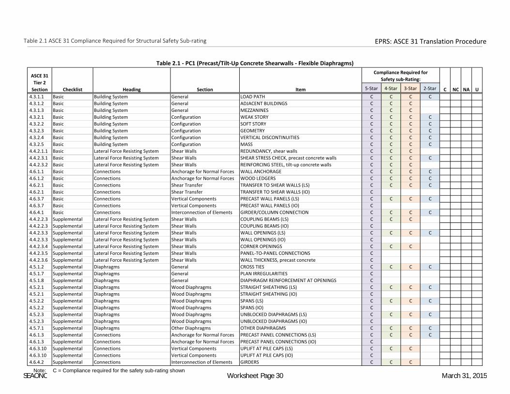
Table 2.1 ASCE 31 Compliance Required for Structural Safety Sub-rating EPRS: ASCE 31 Translation Procedure
5-Star 4-Star 3-Star 2-Star
4.3.1.1 Basic Building System General LOAD PATH C C C C
4.3.1.2 Basic Building System General ADJACENT BUILDINGS C C C
4.3.1.3 Basic Building System General MEZZANINES C C C
4.3.2.1 Basic Building System Configuration WEAK STORY C C C C
4.3.2.2 Basic Building System Configuration SOFT STORY C C C C
4.3.2.3 Basic Building System Configuration GEOMETRY C C C C
4.3.2.4 Basic Building System Configuration VERTICAL DISCONTINUITIES C C C C
4.3.2.5 Basic Building System Configuration MASS C C C C
4.4.2.1.1 Basic Lateral Force Resisting System Shear Walls REDUNDANCY, shear walls C C C
4.4.2.3.1 Basic Lateral Force Resisting System Shear Walls SHEAR STRESS CHECK, precast concrete walls C C C C
4.4.2.3.2 Basic Lateral Force Resisting System Shear Walls REINFORCING STEEL, tilt-up concrete walls C C C
4.6.1.1 Basic Connections Anchorage for Normal Forces WALL ANCHORAGE C C C C
4.6.1.2 Basic Connections Anchorage for Normal Forces WOOD LEDGERS C C C C
4.6.2.1 Basic Connections Shear Transfer TRANSFER TO SHEAR WALLS (LS) C C C C
4.6.2.1 Basic Connections Shear Transfer TRANSFER TO SHEAR WALLS (IO) C
4.6.3.7 Basic Connections Vertical Components PRECAST WALL PANELS (LS) C C C C
4.6.3.7 Basic Connections Vertical Components PRECAST WALL PANELS (IO) C
4.6.4.1 Basic Connections Interconnection of Elements GIRDER/COLUMN CONNECTION C C C C
4.4.2.2.3 Supplemental Lateral Force Resisting System Shear Walls COUPLING BEAMS (LS) C C C
4.4.2.2.3 Supplemental Lateral Force Resisting System Shear Walls COUPLING BEAMS (IO) C
4.4.2.3.3 Supplemental Lateral Force Resisting System Shear Walls WALL OPENINGS (LS) C C C C
4.4.2.3.3 Supplemental Lateral Force Resisting System Shear Walls WALL OPENINGS (IO) C
4.4.2.3.4 Supplemental Lateral Force Resisting System Shear Walls CORNER OPENINGS C C C
4.4.2.3.5 Supplemental Lateral Force Resisting System Shear Walls PANEL-TO-PANEL CONNECTIONS C
4.4.2.3.6 Supplemental Lateral Force Resisting System Shear Walls WALL THICKNESS, precast concrete C
4.5.1.2 Supplemental Diaphragms General CROSS TIES C C C C
4.5.1.7 Supplemental Diaphragms General PLAN IRREGULARITIES C
4.5.1.8 Supplemental Diaphragms General DIAPHRAGM REINFORCEMENT AT OPENINGS C
4.5.2.1 Supplemental Diaphragms Wood Diaphragms STRAIGHT SHEATHING (LS) C C C C
4.5.2.1 Supplemental Diaphragms Wood Diaphragms STRAIGHT SHEATHING (IO) C
4.5.2.2 Supplemental Diaphragms Wood Diaphragms SPANS (LS) C C C C
4.5.2.2 Supplemental Diaphragms Wood Diaphragms SPANS (IO) C
4.5.2.3 Supplemental Diaphragms Wood Diaphragms UNBLOCKED DIAPHRAGMS (LS) C C C C
4.5.2.3 Supplemental Diaphragms Wood Diaphragms UNBLOCKED DIAPHRAGMS (IO) C
4.5.7.1 Supplemental Diaphragms Other Diaphragms OTHER DIAPHRAGMS C C C C
4.6.1.3 Supplemental Connections Anchorage for Normal Forces PRECAST PANEL CONNECTIONS (LS) C C C C
4.6.1.3 Supplemental Connections Anchorage for Normal Forces PRECAST PANEL CONNECTIONS (IO) C
4.6.3.10 Supplemental Connections Vertical Components UPLIFT AT PILE CAPS (LS) C C C
4.6.3.10 Supplemental Connections Vertical Components UPLIFT AT PILE CAPS (IO) C
4.6.4.2 Supplemental Connections Interconnection of Elements GIRDERS C C C
Note: C = Compliance required for the safety sub-rating shown
ASCE 31
Tier 2
Section Checklist Heading Section Item C NC NA U
Compliance Required for
Safety sub-Rating:
Table 2.1 - PC1 (Precast/Tilt-Up Concrete Shearwalls - Flexible Diaphragms)
SEAONC Worksheet Page 30 March 31, 2015

Table 2.1 ASCE 31 Compliance Required for Structural Safety Sub-rating EPRS: ASCE 31 Translation Procedure
5-Star 4-Star 3-Star 2-Star
4.3.1.1 Basic Building System General LOAD PATH C C C C
4.3.1.3 Basic Building System General MEZZANINES C C C
4.3.2.1 Basic Building System Configuration WEAK STORY C C C C
4.3.2.2 Basic Building System Configuration SOFT STORY C C C C
4.3.2.3 Basic Building System Configuration GEOMETRY C C C C
4.3.2.4 Basic Building System Configuration VERTICAL DISCONTINUITIES C C C C
4.3.2.5 Basic Building System Configuration MASS C C C C
4.3.2.6 Basic Building System Configuration TORSION C C C C
4.3.3.5 Basic Building System Condition of Materials POST-TENSIONING ANCHORS C C C
4.4.2.1.1 Basic Lateral Force Resisting System Shear Walls REDUNDANCY, shear walls C C C
4.4.2.3.1 Basic Lateral Force Resisting System Shear Walls SHEAR STRESS CHECK, precast concrete walls C C C C
4.4.2.3.2 Basic Lateral Force Resisting System Shear Walls REINFORCING STEEL, tilt-up concrete walls C C C
4.5.5.1 Basic Diaphragms Precast Concrete Diaphragms TOPPING SLAB C C C C
4.6.1.1 Basic Connections Anchorage for Normal Forces WALL ANCHORAGE C C C C
4.6.2.1 Basic Connections Shear Transfer TRANSFER TO SHEAR WALLS (LS) C C C C
4.6.2.1 Basic Connections Shear Transfer TRANSFER TO SHEAR WALLS (IO) C
4.6.2.3 Basic Connections Shear Transfer TOPPING SLAB TO WALLS OR FRAMES (LS) C C C C
4.6.2.3 Basic Connections Shear Transfer TOPPING SLAB TO WALLS OR FRAMES (IO) C
4.6.3.7 Basic Connections Vertical Components PRECAST WALL PANELS (LS) C C C C
4.6.3.7 Basic Connections Vertical Components PRECAST WALL PANELS (IO) C
4.6.4.1 Basic Connections Interconnection of Elements GIRDER/COLUMN CONNECTION C C C C
4.4.1.6.2 Supplemental Lateral Force Resisting System Moment Frames DEFLECTION COMPATIBILITY (LS) C C C
4.4.1.6.2 Supplemental Lateral Force Resisting System Moment Frames DEFLECTION COMPATIBILITY (IO) C
4.4.2.2.3 Supplemental Lateral Force Resisting System Shear Walls COUPLING BEAMS (LS) C C C
4.4.2.2.3 Supplemental Lateral Force Resisting System Shear Walls COUPLING BEAMS (IO) C
4.4.2.3.3 Supplemental Lateral Force Resisting System Shear Walls WALL OPENINGS (LS) C C C C
4.4.2.3.3 Supplemental Lateral Force Resisting System Shear Walls WALL OPENINGS (IO) C
4.4.2.3.4 Supplemental Lateral Force Resisting System Shear Walls CORNER OPENINGS C C C
4.4.2.3.5 Supplemental Lateral Force Resisting System Shear Walls PANEL-TO-PANEL CONNECTIONS C
4.4.2.3.6 Supplemental Lateral Force Resisting System Shear Walls WALL THICKNESS, precast concrete C
4.5.1.7 Supplemental Diaphragms General PLAN IRREGULARITIES C
4.5.1.8 Supplemental Diaphragms General DIAPHRAGM REINFORCEMENT AT OPENINGS C
4.6.1.3 Supplemental Connections Anchorage for Normal Forces PRECAST PANEL CONNECTIONS (LS) C C C C
4.6.1.3 Supplemental Connections Anchorage for Normal Forces PRECAST PANEL CONNECTIONS (IO) C
4.6.3.10 Supplemental Connections Vertical Components UPLIFT AT PILE CAPS (LS) C C C
4.6.3.10 Supplemental Connections Vertical Components UPLIFT AT PILE CAPS (IO) C
4.6.4.2 Supplemental Connections Interconnection of Elements GIRDERS C C C
Note: C = Compliance required for the safety sub-rating shown
ASCE 31
Tier 2
Section Checklist Heading Section Item C NC NA U
Compliance Required for
Safety sub-Rating:
Table 2.1 - PC1A (Precast/Tilt-Up Concrete Shearwalls - Stiff Diaphragms)
SEAONC Worksheet Page 31 March 31, 2015

Table 2.1 ASCE 31 Compliance Required for Structural Safety Sub-rating EPRS: ASCE 31 Translation Procedure
5-Star 4-Star 3-Star 2-Star
4.3.1.1 Basic Building System General LOAD PATH C C C C
4.3.1.3 Basic Building System General MEZZANINES C C C
4.3.2.1 Basic Building System Configuration WEAK STORY C C C C
4.3.2.2 Basic Building System Configuration SOFT STORY C C C C
4.3.2.3 Basic Building System Configuration GEOMETRY C C C C
4.3.2.4 Basic Building System Configuration VERTICAL DISCONTINUITIES C C C C
4.3.2.5 Basic Building System Configuration MASS C C C C
4.3.2.6 Basic Building System Configuration TORSION C C C C
4.3.3.5 Basic Building System Condition of Materials POST-TENSIONING ANCHORS C C C
4.4.1.6.1 Basic Lateral Force Resisting System Moment Frames COMPLETE FRAMES C C C
4.4.2.1.1 Basic Lateral Force Resisting System Shear Walls REDUNDANCY, shear walls C C C
4.4.2.2.1 Basic Lateral Force Resisting System Shear Walls SHEAR STRESS CHECK, concrete walls C C C C
4.4.2.2.2 Basic Lateral Force Resisting System Shear Walls REINFORCING STEEL, non-tilt-up concrete walls C C C C
4.5.5.1 Basic Diaphragms Precast Concrete Diaphragms TOPPING SLAB C C C C
4.6.1.1 Basic Connections Anchorage for Normal Forces WALL ANCHORAGE C C C C
4.6.2.1 Basic Connections Shear Transfer TRANSFER TO SHEAR WALLS (LS) C C C C
4.6.2.1 Basic Connections Shear Transfer TRANSFER TO SHEAR WALLS (IO) C
4.6.2.3 Basic Connections Shear Transfer TOPPING SLAB TO WALLS OR FRAMES (LS) C C C C
4.6.2.3 Basic Connections Shear Transfer TOPPING SLAB TO WALLS OR FRAMES (IO) C
4.6.3.5 Basic Connections Vertical Components FOUNDATION DOWELS (LS) C C C C
4.6.3.5 Basic Connections Vertical Components FOUNDATION DOWELS (IO) C
4.6.4.1 Basic Connections Interconnection of Elements GIRDER/COLUMN CONNECTION C C C C
4.4.1.5.2 Supplemental Lateral Force Resisting System Moment Frames PRECAST FRAMES C C C C
4.4.1.5.3 Supplemental Lateral Force Resisting System Moment Frames PRECAST CONNECTIONS C C C
4.4.1.6.2 Supplemental Lateral Force Resisting System Moment Frames DEFLECTION COMPATIBILITY (LS) C C C
4.4.1.6.2 Supplemental Lateral Force Resisting System Moment Frames DEFLECTION COMPATIBILITY (IO) C
4.4.2.2.3 Supplemental Lateral Force Resisting System Shear Walls COUPLING BEAMS (LS) C C C
4.4.2.2.3 Supplemental Lateral Force Resisting System Shear Walls COUPLING BEAMS (IO) C
4.4.2.2.4 Supplemental Lateral Force Resisting System Shear Walls OVERTURNING, concrete shear walls C
4.4.2.2.5 Supplemental Lateral Force Resisting System Shear Walls CONFINEMENT REINFORCING C
4.4.2.2.6 Supplemental Lateral Force Resisting System Shear Walls REINFORCING AT OPENINGS, concrete walls C
4.4.2.2.7 Supplemental Lateral Force Resisting System Shear Walls WALL THICKNESS, cast-in-place concrete C
4.5.1.4 Supplemental Diaphragms General OPENINGS AT SHEAR WALLS (LS) C C C
4.5.1.4 Supplemental Diaphragms General OPENINGS AT SHEAR WALLS (IO) C
4.5.1.7 Supplemental Diaphragms General PLAN IRREGULARITIES C
4.5.1.8 Supplemental Diaphragms General DIAPHRAGM REINFORCEMENT AT OPENINGS C
4.6.3.10 Supplemental Connections Vertical Components UPLIFT AT PILE CAPS (LS) C C C
4.6.3.10 Supplemental Connections Vertical Components UPLIFT AT PILE CAPS (IO) C
4.6.4.3 Supplemental Connections Interconnection of Elements CORBEL BEARING C C C
4.6.4.4 Supplemental Connections Interconnection of Elements CORBEL CONNECTIONS C C C
Note: C = Compliance required for the safety sub-rating shown
ASCE 31
Tier 2
Section Checklist Heading Section Item C NC NA U
Compliance Required for
Safety sub-Rating:
Table 2.1 - PC2 (Precast Concrete Frames with Shearwalls)
SEAONC Worksheet Page 32 March 31, 2015

Table 2.1 ASCE 31 Compliance Required for Structural Safety Sub-rating EPRS: ASCE 31 Translation Procedure
5-Star 4-Star 3-Star 2-Star
4.3.1.1 Basic Building System General LOAD PATH C C C C
4.3.1.2 Basic Building System General ADJACENT BUILDINGS C C C
4.3.1.3 Basic Building System General MEZZANINES C C C
4.3.2.1 Basic Building System Configuration WEAK STORY C C C C
4.3.2.2 Basic Building System Configuration SOFT STORY C C C C
4.3.2.3 Basic Building System Configuration GEOMETRY C C C C
4.3.2.4 Basic Building System Configuration VERTICAL DISCONTINUITIES C C C C
4.3.2.5 Basic Building System Configuration MASS C C C C
4.3.2.6 Basic Building System Configuration TORSION C C C C
4.3.3.5 Basic Building System Condition of Materials POST-TENSIONING ANCHORS C C C
4.4.1.1.1 Basic Lateral Force Resisting System Moment Frames REDUNDANCY, moment frames (LS) C C C
4.4.1.1.1 Basic Lateral Force Resisting System Moment Frames REDUNDANCY, moment frames (IO) C
4.4.1.4.1 Basic Lateral Force Resisting System Moment Frames SHEAR STRESS CHECK, concrete columns C C C C
4.4.1.4.2 Basic Lateral Force Resisting System Moment Frames AXIAL STRESS CHECK, concrete columns C C C C
4.4.1.5.1 Basic Lateral Force Resisting System Moment Frames PRECAST CONNECTION CHECK C C C C
4.5.5.1 Basic Diaphragms Precast Concrete Diaphragms TOPPING SLAB C C C C
4.6.2.3 Basic Connections Shear Transfer TOPPING SLAB TO WALLS OR FRAMES (LS) C C C C
4.6.2.3 Basic Connections Shear Transfer TOPPING SLAB TO WALLS OR FRAMES (IO) C
4.6.4.1 Basic Connections Interconnection of Elements GIRDER/COLUMN CONNECTION C C C C
4.4.1.4.4 Supplemental Lateral Force Resisting System Moment Frames PRESTRESSED FRAME ELEMENTS C C C
4.4.1.4.5 Supplemental Lateral Force Resisting System Moment Frames CAPTIVE COLUMNS (LS) C C C C
4.4.1.4.5 Supplemental Lateral Force Resisting System Moment Frames CAPTIVE COLUMNS (IO) C
4.4.1.4.13 Supplemental Lateral Force Resisting System Moment Frames JOINT REINFORCING C C C C
4.4.1.6.2 Supplemental Lateral Force Resisting System Moment Frames DEFLECTION COMPATIBILITY (LS) C C C C
4.4.1.6.2 Supplemental Lateral Force Resisting System Moment Frames DEFLECTION COMPATIBILITY (IO) C
4.5.1.7 Supplemental Diaphragms General PLAN IRREGULARITIES C
4.5.1.8 Supplemental Diaphragms General DIAPHRAGM REINFORCEMENT AT OPENINGS C
4.6.3.10 Supplemental Connections Vertical Components UPLIFT AT PILE CAPS (LS) C C C
4.6.3.10 Supplemental Connections Vertical Components UPLIFT AT PILE CAPS (IO) C
4.6.4.2 Supplemental Connections Interconnection of Elements GIRDERS C C C
4.6.4.3 Supplemental Connections Interconnection of Elements CORBEL BEARING C C C
4.6.4.4 Supplemental Connections Interconnection of Elements CORBEL CONNECTIONS C C C
Note: C = Compliance required for the safety sub-rating shown
ASCE 31
Tier 2
Section Checklist Heading Section Item C NC NA U
Compliance Required for
Safety sub-Rating:
Table 2.1 - PC2A (Precast Concrete Frames without Shearwalls)
SEAONC Worksheet Page 33 March 31, 2015

Table 2.1 ASCE 31 Compliance Required for Structural Safety Sub-rating EPRS: ASCE 31 Translation Procedure
5-Star 4-Star 3-Star 2-Star
4.3.1.1 Basic Building System General LOAD PATH C C C C
4.3.1.2 Basic Building System General ADJACENT BUILDINGS C C C
4.3.1.3 Basic Building System General MEZZANINES C C C
4.3.2.1 Basic Building System Configuration WEAK STORY C C C C
4.3.2.2 Basic Building System Configuration SOFT STORY C C C C
4.3.2.3 Basic Building System Configuration GEOMETRY C C C C
4.3.2.4 Basic Building System Configuration VERTICAL DISCONTINUITIES C C C C
4.3.2.5 Basic Building System Configuration MASS C C C C
4.4.2.1.1 Basic Lateral Force Resisting System Shear Walls REDUNDANCY, shear walls C C C
4.4.2.4.1 Basic Lateral Force Resisting System Shear Walls SHEAR STRESS CHECK, reinforced masonry walls C C C C
4.4.2.4.2 Basic Lateral Force Resisting System Shear Walls REINFORCING STEEL, reinforced masonry C C C
4.6.1.1 Basic Connections Anchorage for Normal Forces WALL ANCHORAGE C C C C
4.6.1.2 Basic Connections Anchorage for Normal Forces WOOD LEDGERS C C C C
4.6.2.1 Basic Connections Shear Transfer TRANSFER TO SHEAR WALLS (LS) C C C C
4.6.2.1 Basic Connections Shear Transfer TRANSFER TO SHEAR WALLS (IO) C
4.6.3.5 Basic Connections Vertical Components FOUNDATION DOWELS (LS) C C C C
4.6.3.5 Basic Connections Vertical Components FOUNDATION DOWELS (IO) C
4.6.4.1 Basic Connections Interconnection of Elements GIRDER/COLUMN CONNECTION C C C C
4.4.2.4.3 Supplemental Lateral Force Resisting System Shear Walls REINFORCING AT OPENINGS, masonry walls C
4.4.2.4.4 Supplemental Lateral Force Resisting System Shear Walls PROPORTIONS, reinforced masonry C C C
4.5.1.2 Supplemental Diaphragms General CROSS TIES C C C C
4.5.1.4 Supplemental Diaphragms General OPENINGS AT SHEAR WALLS (LS) C C C
4.5.1.4 Supplemental Diaphragms General OPENINGS AT SHEAR WALLS (IO) C
4.5.1.6 Supplemental Diaphragms General OPENINGS AT EXTERIOR MASONRY SHEAR WALLS (LS) C C C
4.5.1.6 Supplemental Diaphragms General OPENINGS AT EXTERIOR MASONRY SHEAR WALLS (IO) C
4.5.1.7 Supplemental Diaphragms General PLAN IRREGULARITIES C
4.5.1.8 Supplemental Diaphragms General DIAPHRAGM REINFORCEMENT AT OPENINGS C
4.5.2.1 Supplemental Diaphragms Wood Diaphragms STRAIGHT SHEATHING (LS) C C C C
4.5.2.1 Supplemental Diaphragms Wood Diaphragms STRAIGHT SHEATHING (IO) C
4.5.2.2 Supplemental Diaphragms Wood Diaphragms SPANS (LS) C C C C
4.5.2.2 Supplemental Diaphragms Wood Diaphragms SPANS (IO) C
4.5.2.3 Supplemental Diaphragms Wood Diaphragms UNBLOCKED DIAPHRAGMS (LS) C C C C
4.5.2.3 Supplemental Diaphragms Wood Diaphragms UNBLOCKED DIAPHRAGMS (IO) C
4.5.3.1 Supplemental Diaphragms Metal Deck Diaphragms NON-CONCRETE FILLED DIAPHRAGMS C
4.5.7.1 Supplemental Diaphragms Other Diaphragms OTHER DIAPHRAGMS C C C C
4.6.1.4 Supplemental Connections Anchorage for Normal Forces STIFFNESS OF WALL ANCHORS C C C
Note: C = Compliance required for the safety sub-rating shown
ASCE 31
Tier 2
Section Checklist Heading Section Item C NC NA U
Compliance Required for
Safety sub-Rating:
Table 2.1 - RM1 (Reinforced Masonry Bearing Walls - Flexible Diaphragms)
SEAONC Worksheet Page 34 March 31, 2015

Table 2.1 ASCE 31 Compliance Required for Structural Safety Sub-rating EPRS: ASCE 31 Translation Procedure
5-Star 4-Star 3-Star 2-Star
4.3.1.1 Basic Building System General LOAD PATH C C C C
4.3.1.3 Basic Building System General MEZZANINES C C C
4.3.2.1 Basic Building System Configuration WEAK STORY C C C C
4.3.2.2 Basic Building System Configuration SOFT STORY C C C C
4.3.2.3 Basic Building System Configuration GEOMETRY C C C C
4.3.2.4 Basic Building System Configuration VERTICAL DISCONTINUITIES C C C C
4.3.2.5 Basic Building System Configuration MASS C C C C
4.3.2.6 Basic Building System Configuration TORSION C C C C
4.4.2.1.1 Basic Lateral Force Resisting System Shear Walls REDUNDANCY, shear walls C C C
4.4.2.4.1 Basic Lateral Force Resisting System Shear Walls SHEAR STRESS CHECK, reinforced masonry walls C C C C
4.4.2.4.2 Basic Lateral Force Resisting System Shear Walls REINFORCING STEEL, reinforced masonry C C C
4.5.5.1 Basic Diaphragms Precast Concrete Diaphragms TOPPING SLAB C C C C
4.6.1.1 Basic Connections Anchorage for Normal Forces WALL ANCHORAGE C C C C
4.6.2.1 Basic Connections Shear Transfer TRANSFER TO SHEAR WALLS (LS) C C C C
4.6.2.1 Basic Connections Shear Transfer TRANSFER TO SHEAR WALLS (IO) C
4.6.2.3 Basic Connections Shear Transfer TOPPING SLAB TO WALLS OR FRAMES (LS) C C C C
4.6.2.3 Basic Connections Shear Transfer TOPPING SLAB TO WALLS OR FRAMES (IO) C
4.6.3.5 Basic Connections Vertical Components FOUNDATION DOWELS (LS) C C C C
4.6.3.5 Basic Connections Vertical Components FOUNDATION DOWELS (IO) C
4.6.4.1 Basic Connections Interconnection of Elements GIRDER/COLUMN CONNECTION C C C C
4.4.2.4.3 Supplemental Lateral Force Resisting System Shear Walls REINFORCING AT OPENINGS, masonry walls C
4.4.2.4.4 Supplemental Lateral Force Resisting System Shear Walls PROPORTIONS, reinforced masonry C C C
4.5.1.4 Supplemental Diaphragms General OPENINGS AT SHEAR WALLS (LS) C C C
4.5.1.4 Supplemental Diaphragms General OPENINGS AT SHEAR WALLS (IO) C
4.5.1.6 Supplemental Diaphragms General OPENINGS AT EXTERIOR MASONRY SHEAR WALLS (LS) C C C
4.5.1.6 Supplemental Diaphragms General OPENINGS AT EXTERIOR MASONRY SHEAR WALLS (IO) C
4.5.1.7 Supplemental Diaphragms General PLAN IRREGULARITIES C
4.5.1.8 Supplemental Diaphragms General DIAPHRAGM REINFORCEMENT AT OPENINGS C
Note: C = Compliance required for the safety sub-rating shown
ASCE 31
Tier 2
Section Checklist Heading Section Item C NC NA U
Compliance Required for
Safety sub-Rating:
Table 2.1 - RM2 (Reinforced Masonry Bearing Walls - Stiff Diaphragms)
SEAONC Worksheet Page 35 March 31, 2015

Table 2.1 ASCE 31 Compliance Required for Structural Safety Sub-rating EPRS: ASCE 31 Translation Procedure
5-Star 4-Star 3-Star 2-Star
4.3.1.1 Basic Building System General LOAD PATH C C C C
4.3.1.2 Basic Building System General ADJACENT BUILDINGS C C C
4.3.1.3 Basic Building System General MEZZANINES C C C
4.3.2.1 Basic Building System Configuration WEAK STORY C C C C
4.3.2.2 Basic Building System Configuration SOFT STORY C C C C
4.3.2.3 Basic Building System Configuration GEOMETRY C C C C
4.3.2.4 Basic Building System Configuration VERTICAL DISCONTINUITIES C C C C
4.3.2.5 Basic Building System Configuration MASS C C C C
4.4.2.1.1 Basic Lateral Force Resisting System Shear Walls REDUNDANCY, shear walls C C C
4.4.2.5.1 Basic Lateral Force Resisting System Shear Walls SHEAR STRESS CHECK, URM walls C C C C
4.6.1.1 Basic Connections Anchorage for Normal Forces WALL ANCHORAGE C C C C
4.6.1.2 Basic Connections Anchorage for Normal Forces WOOD LEDGERS C C C C
4.6.2.1 Basic Connections Shear Transfer TRANSFER TO SHEAR WALLS (LS) C C C C
4.6.2.1 Basic Connections Shear Transfer TRANSFER TO SHEAR WALLS (IO) C
4.6.4.1 Basic Connections Interconnection of Elements GIRDER/COLUMN CONNECTION C C C C
4.4.2.5.2 Supplemental Lateral Force Resisting System Shear Walls PROPORTIONS, URM C C C C
4.4.2.5.3 Supplemental Lateral Force Resisting System Shear Walls MASONRY LAY-UP C C C
4.5.1.2 Supplemental Diaphragms General CROSS TIES C C C C
4.5.1.4 Supplemental Diaphragms General OPENINGS AT SHEAR WALLS (LS) C C C
4.5.1.4 Supplemental Diaphragms General OPENINGS AT SHEAR WALLS (IO) C
4.5.1.6 Supplemental Diaphragms General OPENINGS AT EXTERIOR MASONRY SHEAR WALLS (LS) C C C
4.5.1.6 Supplemental Diaphragms General OPENINGS AT EXTERIOR MASONRY SHEAR WALLS (IO) C
4.5.1.7 Supplemental Diaphragms General PLAN IRREGULARITIES C
4.5.1.8 Supplemental Diaphragms General DIAPHRAGM REINFORCEMENT AT OPENINGS C
4.5.2.1 Supplemental Diaphragms Wood Diaphragms STRAIGHT SHEATHING (LS) C C C C
4.5.2.1 Supplemental Diaphragms Wood Diaphragms STRAIGHT SHEATHING (IO) C
4.5.2.2 Supplemental Diaphragms Wood Diaphragms SPANS (LS) C C C C
4.5.2.2 Supplemental Diaphragms Wood Diaphragms SPANS (IO) C
4.5.2.3 Supplemental Diaphragms Wood Diaphragms UNBLOCKED DIAPHRAGMS (LS) C C C C
4.5.2.3 Supplemental Diaphragms Wood Diaphragms UNBLOCKED DIAPHRAGMS (IO) C
4.5.3.1 Supplemental Diaphragms Metal Deck Diaphragms NON-CONCRETE FILLED DIAPHRAGMS C
4.5.7.1 Supplemental Diaphragms Other Diaphragms OTHER DIAPHRAGMS C C C C
4.6.1.4 Supplemental Connections Anchorage for Normal Forces STIFFNESS OF WALL ANCHORS C C C
4.6.4.5 Supplemental Connections Interconnection of Elements BEAM, GIRDER AND TRUSS SUPPORTS C C C C
Note: C = Compliance required for the safety sub-rating shown
ASCE 31
Tier 2
Section Checklist Heading Section Item C NC NA U
Compliance Required for
Safety sub-Rating:
Table 2.1 - URM (Unreinforced Masonry Bearing Walls - Flexible Diaphragms)
SEAONC Worksheet Page 36 March 31, 2015

Table 2.1 ASCE 31 Compliance Required for Structural Safety Sub-rating EPRS: ASCE 31 Translation Procedure
5-Star 4-Star 3-Star 2-Star
4.3.1.1 Basic Building System General LOAD PATH C C C C
4.3.1.3 Basic Building System General MEZZANINES C C C
4.3.2.1 Basic Building System Configuration WEAK STORY C C C C
4.3.2.2 Basic Building System Configuration SOFT STORY C C C C
4.3.2.3 Basic Building System Configuration GEOMETRY C C C C
4.3.2.4 Basic Building System Configuration VERTICAL DISCONTINUITIES C C C C
4.3.2.5 Basic Building System Configuration MASS C C C C
4.3.2.6 Basic Building System Configuration TORSION C C C C
4.4.2.1.1 Basic Lateral Force Resisting System Shear Walls REDUNDANCY, shear walls C C C
4.4.2.5.1 Basic Lateral Force Resisting System Shear Walls SHEAR STRESS CHECK, URM walls C C C C
4.6.1.1 Basic Connections Anchorage for Normal Forces WALL ANCHORAGE C C C C
4.6.2.1 Basic Connections Shear Transfer TRANSFER TO SHEAR WALLS (LS) C C C C
4.6.2.1 Basic Connections Shear Transfer TRANSFER TO SHEAR WALLS (IO) C
4.6.4.1 Basic Connections Interconnection of Elements GIRDER/COLUMN CONNECTION C C C C
4.4.2.5.2 Supplemental Lateral Force Resisting System Shear Walls PROPORTIONS, URM C C C C
4.4.2.5.3 Supplemental Lateral Force Resisting System Shear Walls MASONRY LAY-UP C C C
4.5.1.4 Supplemental Diaphragms General OPENINGS AT SHEAR WALLS (LS) C C C
4.5.1.4 Supplemental Diaphragms General OPENINGS AT SHEAR WALLS (IO) C
4.5.1.6 Supplemental Diaphragms General OPENINGS AT EXTERIOR MASONRY SHEAR WALLS (LS) C C C
4.5.1.6 Supplemental Diaphragms General OPENINGS AT EXTERIOR MASONRY SHEAR WALLS (IO) C
4.5.1.7 Supplemental Diaphragms General PLAN IRREGULARITIES C
4.5.1.8 Supplemental Diaphragms General DIAPHRAGM REINFORCEMENT AT OPENINGS C
4.6.4.5 Supplemental Connections Interconnection of Elements BEAM, GIRDER AND TRUSS SUPPORTS C C C C
Note: C = Compliance required for the safety sub-rating shown
ASCE 31
Tier 2
Section Checklist Heading Section Item C NC NA U
Compliance Required for
Safety sub-Rating:
Table 2.1 - URMA (Unreinforced Masonry Bearing Walls - Stiff Diaphragms)
SEAONC Worksheet Page 37 March 31, 2015

Table 2.2 ASCE 31 Compliance Required for Geologic/Foundation Safety Sub-rating EPRS: ASCE 31 Translation Procedure
5-Star 4-Star 3-Star 2-Star
4.7.1.1 Geologic Site Hazards and Foundations Geologic Site Hazards LIQUEFACTION C C C
4.7.1.2 Geologic Site Hazards and Foundations Geologic Site Hazards SLOPE FAILURE C C C C
4.7.1.3 Geologic Site Hazards and Foundations Geologic Site Hazards SURFACE FAULT RUPTURE C C C C
4.7.3.1 Geologic Site Hazards and Foundations Capacity of Foundations POLE FOUNDATIONS C C C C
4.7.3.2 Geologic Site Hazards and Foundations Capacity of Foundations OVERTURNING, foundations C C C
4.7.3.3 Geologic Site Hazards and Foundations Capacity of Foundations TIES BETWEEN FOUNDATION ELEMENTS C C C
4.7.3.4 Geologic Site Hazards and Foundations Capacity of Foundations DEEP FOUNDATIONS C
4.7.3.5 Geologic Site Hazards and Foundations Capacity of Foundations SLOPING SITES C
Note: C = Compliance required for the Geologic Site Hazards and Foundations Safety sub-rating shown
NA U
Table 2.2 - Geologic Site Hazards and Foundations
ASCE 31
Tier 2
Section Checklist Heading Item
Compliance Required for
Geologic/Foundation Sub-rating:
C NC
SEAONC Worksheet Page 38 March 31, 2015