earth pressure on retaining walls in abaquslateral earth pressure and retaining walls in abaqus...
TRANSCRIPT

LATERAL EARTH PRESSURE AND RETAINING WALLS IN ABAQUS
Calculation of at-rest and active lateral earth pressure using a Finite ElementModel – an ABAQUS tutorial
Professor: Dr.-Ing. William Fuentes
Student: Melany Gil Rueda
Department of Civil and Environmental Engineering
Universidad del Norte
Barranquilla, Colombia
2018

Problem
A 3-m-high backfill sand is supported by a concrete retaining wall and is subjected to a 10 kPa surcharge pressure onthe top. Calculate the at-rest and active lateral earth pressure acting against the wall using a Finite Element Modelbuilt in Abaqus.
30

Overview of the model: ‘Active failure’
• At rest U1 = 0
• Active U1 = - 0.005 m
Soil-structure
interaction
2 steps will be set: First, the Geostatic step and then the Displacement step (Active). After the first step, the at-restlateral earth pressure is obtained. After the second step, the Active lateral earth pressure is obtained.

Module: Part1- From the Module
list select theModule: Part
2- Click on theCreate Part tool
3- Fill the dialog box to create the firstpart: Soil
123
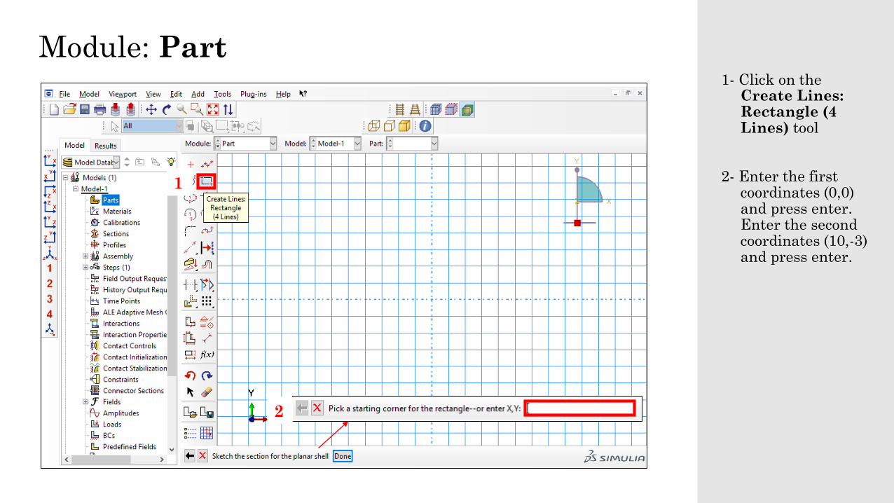
Module: Part1- Click on the
Create Lines: Rectangle (4 Lines) tool
2- Enter the firstcoordinates (0,0) and press enter. Enter the secondcoordinates (10,-3) and press enter.
1
2

Module: Part1- Click on the red
cross to end theprocedure
2- Click on Done
1
2
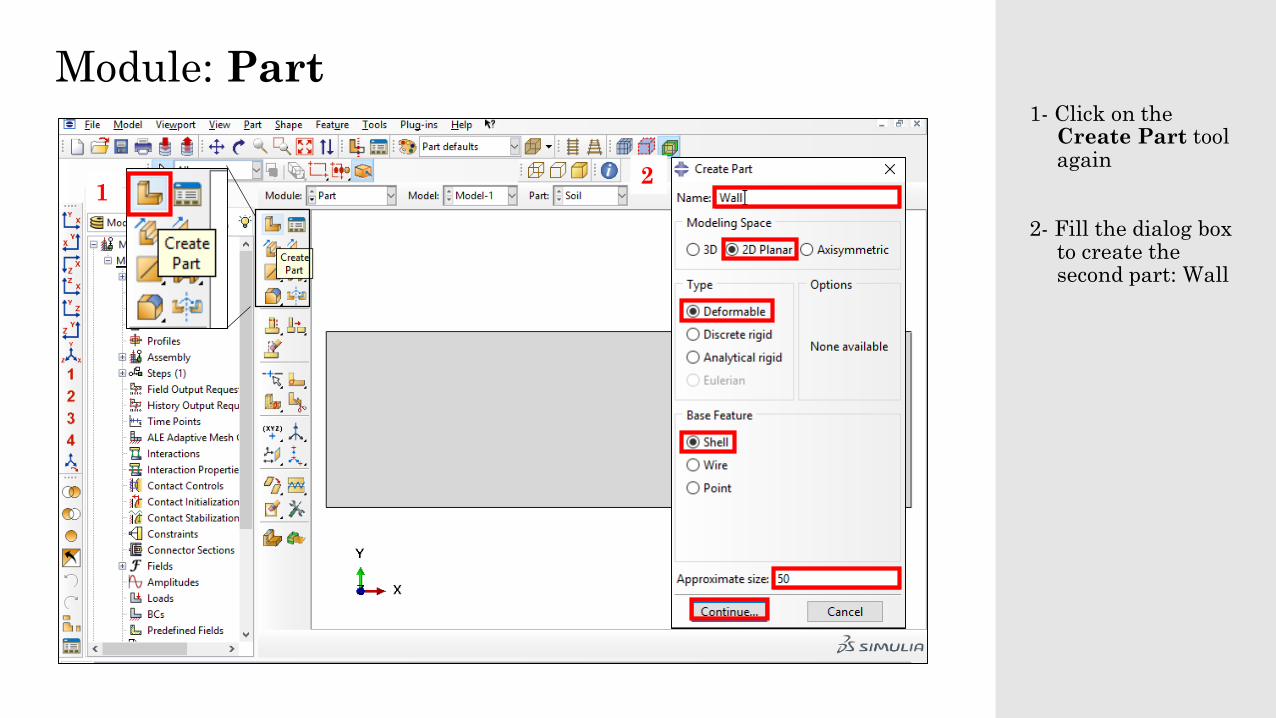
Module: Part1- Click on the
Create Part toolagain
2- Fill the dialog box to create thesecond part: Wall
12
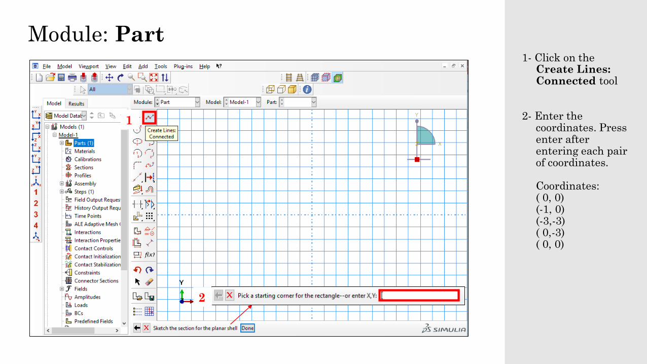
Module: Part1- Click on the
Create Lines: Connected tool
2- Enter thecoordinates. Pressenter after entering each pairof coordinates.
Coordinates:( 0, 0)(-1, 0)(-3,-3)( 0,-3)( 0, 0)
1
2

Module: Part1- Click on the red
cross to end theprocedure
2- Click on Done
1
2

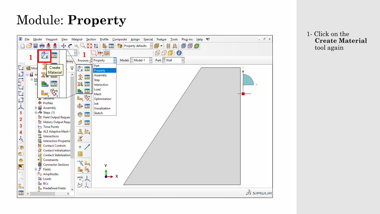
Module: Property1- From the Module
list select theModule: Property
2- Click on theCreate Material tool
12

Module: Property1- Fill the dialog box
to create the firstmaterial: Soil. In this case, a Drucker Prager/cap modelwill be used.
2- Click on General and then onDensity
3-Enter the densityas 1.7 kg/m3
1
2
3

Module: Property1- Click on
Mechanical, Elasticity and then on Elastic
2-Enter theparameters:
Young’s Modulus, E = 10000 kPa
Poisson’s Ratio,v = 0.3
1
2

Module: Property1- Click on
Mechanical, Plasticity and then on Mohr Coulomb Plasticity
1

Module: Property1- Enter the
parameters1
Module: Property1- Click on the
Create Material tool again
11

Module: Property1- Fill the dialog box
to create thesecond material: Concrete.
2- Click on General and then onDensity
3-Enter the densityas 2.4 kg/m3
1
2
3

Module: Property1- Click on
Mechanical, Elasticity and then on Elastic
2-Enter theparameters:
Young’s Modulus, E = 20∙106 kPa
Poisson’s Ratio, v = 0.2
1
2

Module: Property1- Click on the
Create Sectiontool
2- Fill the dialog box to create the firstsection (Soil) as anHomogeneousSolid section. Click onContinue
3- In the Edit Sectiondialog box, choose‘Soil’ as thematerial and clickon OK.
1
2 3

Module: Property1- Click on the
Create Sectiontool
2- Fill the dialog box to create thesecond section(Wall) as anHomogeneousSolid section. Click onContinue
3- In the Edit Sectiondialog box, choose‘Concrete’ as thematerial and clickon OK.
1
2 3

Module: Property1- Click on the
Assign Sectiontool
2- Name the new set as ‘wall’
3- Click inside theregion of the walland it will turnred
4- Click on Done
5- In the Edit SectionAssigment dialogbox, choose ‘Wall’ as the section and click on OK.
1
2
3
4
5

Module: Property1- From the Part List
select the Part: Soil
2- Click on theAssign Sectiontool
3- Name the new set as ‘soil’’
4- Click inside theregion of the soiland it will turnred
5- Click on Done
6- In the Edit SectionAssigment dialogbox, choose ‘Soil’ as the section and click on OK.
2
3
4
5
6
1

Module: Assembly1- From the Module
list select theModule: Assembly
2- Click on theInstance Parttool
3- In the CreateInstance dialogbox, Click on Soiland on OK
4- Repeat the firsttwo steps and in the dialog box, click on Wall and on OK
12
3 4

Module: Assembly

Module: Step1- From the Module
list select theModule: Step
2- Click on theCreate Step tool
3- In the Create Step dialog box, namethe first step as ‘Geostatic’ and select ‘General’, and ‘Geostatic’. Click onContinue
1
23

Module: Step1- In the Edit Step
dialog box, select‘Automatic’ as theIncrementation Type. Then, clickon OK
1

Module: Step1- Click on the
Create Step tool
2- In the Create Step dialog box, namethe second step as ‘Displacement’ and select ‘General’, and ‘Static, General’ as theProcedure Type. Click onContinue
1
2

Module: Step1- In the Edit Step
dialog box, select‘Automatic’ as theIncrementation Type and complete the dialog box. Then, click on OK1

Module: Interaction1- From the Module
list select theModule: Interaction
2- Click on theCreateInteractionProperty tool
3- In the dialog box, name theinteractionproperty as ‘IntProp’ and select ‘Contact’’. Click onContinue
12
3

Module: Interaction1- Click on
Mechanical and on TangentialBehavior
2- Select Penalty as the FrictionFormulation and set the FrictionCoefficient astan(2/3 30°) = 0.36
1 2

Module: Interaction1- Click on
Mechanical and on Normal Behavior
2- Click on OK
1
2