earth location user’s guide (elug) - nasa · dcn 1 earth location user’s guide (elug) revision...
TRANSCRIPT

NOAA/NESDIS NOAA/OSD3-1998-015R1UD0
DRL 504-11 March 16, 1998
DCN 1
Earth Location User’s Guide(ELUG)
Revision 1
March 1998
Prepared by:
U.S. Department of Commerce
National Oceanic and Atmospheric Administration (NOAA)
National Environmental Satellite, Data, and Information Service (NESDIS)

NOAA/NESDIS NOAA/OSD3-1998-015R1UD0
DRL 504-11 March 16, 1998
DCN 1

NOAA/NESDIS NOAA/OSD3-1998-015R1UD0
DRL 504-11 March 16, 1998
DCN 1
AK-1
Acknowledgments
Previous Versions. NOAA/NESDIS acknowledges the efforts of Space Systems/Loral (SS/L)and Integral Systems, Incorporated (ISI) for their preparation of the original version of thisdocument, SS/L-TR00689, published January 13, 1994, and ISI-36-439 (Revision A) publishedSeptember 26, 1994, under National Aeronautics and Space Administration (NASA) ContractNAS 5-29500. ISI is also acknowledged for contributions to the NOAA/NESDIS DCN 0baseline of the document, ISI-36-439R0UD0, published May 15, 1997.
Current Version. NOAA/NESDIS acknowledges the contributions of the following companiesin the content update of this Revision 1 document baseline:
< Lockheed-Martin Space Mission Systems and Services (LMSMS&S)< Swales Aerospace< Integral Systems, Incorporated (ISI)
NOAA/NESDIS NOAA/OSD3-1998-015R1UD0
DRL 504-11 March 16, 1998
DCN 1
i
Table of Contents
1.0 Introduction ........................................................................................................................ 1-11.1 Overview .................................................................................................................. 1-1
1.1.1 Instrument Coordinate Systems.................................................................... 1-21.1.2 Earth Location Processing............................................................................ 1-8
1.2 Document Organization ......................................................................................... 1-10
2.0 Auxiliary GVAR Data........................................................................................................ 2-12.1 Orbit and Attitude (O&A) Coefficient Set............................................................... 2-1
2.1.1 O&A Format Description............................................................................. 2-12.1.2 Notation Conversion..................................................................................... 2-7
2.2 Yaw Flip Flag........................................................................................................... 2-72.3 Nadir Offset.............................................................................................................. 2-7
3.0 Mathematical Description of Instrument Related Coordinate Systems ............................. 3-13.1 Parameters for the Coordinate Transformations ...................................................... 3-13.2 Cycle and Increments ............................................................................................... 3-13.3 Lines and Pixels........................................................................................................ 3-23.4 Elevation and Scan Angles....................................................................................... 3-33.5 Notes on the Instrument-Related Coordinate Systems............................................. 3-53.6 Cycles/Increments to Elevation and Scan Angles Conversion ................................ 3-93.7 Line/Pixel to Elevation/Scan Angle Conversion...................................................... 3-93.8 Optical Axis Correction.......................................................................................... 3-10
4.0 Transformations Between the Instrument and Geographic Coordinates............................ 4-14.1 Orbit Model .............................................................................................................. 4-14.2 Spacecraft to Earth-Fixed Coordinates Transformation........................................... 4-34.3 Attitude Angles and Attitude Misalignments........................................................... 4-54.4 Instrument to Earth-Fixed Coordinates Transformation .......................................... 4-64.5 Pointing Vectors in the Instrument Frame ............................................................... 4-64.6 Geographic to Instrument Coordinates Transformation........................................... 4-84.7 Instrument to Geographic Coordinates Transformation......................................... 4-104.8 Year and Day of Year to Julian Day Transformation............................................. 4-11
5.0 Module Descriptions .......................................................................................................... 5-15.1 Subroutine LMODEL............................................................................................... 5-15.2 Subroutine INST2ER ............................................................................................... 5-25.3 Function GATT........................................................................................................ 5-25.4 Subroutine LPOINT ................................................................................................. 5-35.5 Subroutine GPOINT................................................................................................. 5-3

NOAA/NESDIS NOAA/OSD3-1998-015R1UD0
DRL 504-11 March 16, 1998
DCN 1
ii
5.6 Subroutine SNDELOC............................................................................................. 5-45.7 Function TIME50..................................................................................................... 5-45.8 Subroutine SETCONS.............................................................................................. 5-55.9 Function EVLN........................................................................................................ 5-55.10 Subroutine SCPX ..................................................................................................... 5-55.11 Subroutine EVSC2LPF ............................................................................................ 5-6
6.0 Test Cases........................................................................................................................... 6-1
Appendix A. Example of OGE Earth Location Software Usage............................................... A-1
Appendix B. OGE Earth Location Software Listings.................................................................B-1
Appendix C. Kamel to Keplerian Transformation......................................................................C-1
List of Figures
1-1 Imager Coordinates and Frames (Upright) ...................................................................... 1-41-2 Sounder Coordinates and Frames (Upright) .................................................................... 1-51-3 Imager Coordinates and Frames (Inverted) ..................................................................... 1-61-4 Sounder Coordinates and Frames (Inverted) ................................................................... 1-73-1 ELVMAX and SCNMAX for a Normal Spacecraft ........................................................ 3-43-2 ELVMAX and SCNMAX for a Flipped Spacecraft ........................................................ 3-63-3 Elevation and Line Coordinates of the Imager for a Normal Spacecraft......................... 3-63-4 Elevation and Line Coordinates of the Imager for a Flipped Spacecraft......................... 3-63-5 Instrument Optical Axis and Detector Pointings ............................................................. 3-74-1 Spacecraft Coordinate System Geometry ........................................................................ 4-44-2 Instrument Angle Geometry............................................................................................. 4-7
List of Tables
2-1 Imager Documentation Block 0 Format Definition ......................................................... 2-32-2 Sounder Instrumentation Documentation Block.............................................................. 2-53-1 Line 1 Pixel 1 Cycles and Increments.............................................................................. 3-2

NOAA/NESDIS NOAA/OSD3-1998-015R1UD0
DRL 504-11 March 16, 1998
DCN 1
1-1
1.0 Introduction
This document provides GOES I-M users with the information describing the process of Earthlocating imagery formatted into the GOES Variable (GVAR) data stream. The informationprovided is a description of the Earth location algorithm used by the Sensor ProcessingSubsystem (SPS) of the Operations Ground Equipment (OGE) and its software implementation.The descriptions provided assume knowledge of the Imager and Sounder instruments and theGVAR format. The Imager and Sounder instrument characteristics and the GVAR data formatare, respectively, described in the Imager/Sounder – OGE Interface Control Document (FordAerospace Corporation (FAC) specification #SJ572022) and the OGE Interface Specification(DRL 504-02), which were developed for the GOES I-M satellite program.
The manual is organized to provide a GOES user with a complete description of the functionalprocess and relevant OGE software implementation. The specific organization is as follows:
Section 1. Overview of the process, which includes brief descriptions of the coordinatesystems, orbit and attitude (O&A) determination process, and relevant GOES userEarth location coordinate transformations.
Section 2. Description of the O&A coefficient set contents as transmitted in the GVARformat. This is the set used to determine spacecraft position and instrumentattitude.
Section 3. Mathematical description of the instrument-related coordinate systems and thetransformation between these coordinate systems.
Section 4. Mathematical description of the transformations between the instrument-relatedcoordinate systems and geographic coordinates.
Section 5. Module descriptions of applicable software as implemented in the OGE's SensorProcessing Subsystem (SPS).
Section 6. Test cases for use in verifying user implementations of Earth location software.
Appendix A. Example of Earth Location Software Module Usage (modules described inSection 5).
Appendix B. Fortran listings of the software described in Section 5.
Appendix C. Kamel to Keplerian Transformation.
1.1 Overview
Earth location determination involves the computation of transformations between geographicand instrument coordinate systems. This allows the determination of the pixel location within aprocessed frame of imagery corresponding to a selected geographic location. A brief description
NOAA/NESDIS NOAA/OSD3-1998-015R1UD0
DRL 504-11 March 16, 1998
DCN 1
1-2
of the instrument coordinate systems used is provided in the next section prior to continuing withthe overview of the transformation process.
While modifying the O&A model for flipped spacecraft, the instrument misalignment terms werefound to be incomplete. The misalignment terms were correct for the Imager (and the Sounderin inverted mode) but were incorrect for the Sounder (and the Imager in inverted mode). Themodifications to the misalignment model have been included in this update of the Earth LocationUser’s Guide. The misalignment corrections now vary with instrument and spacecraftorientation.
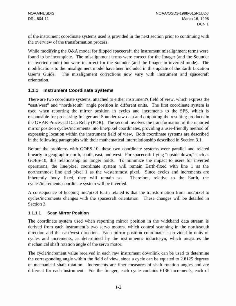
1.1.1 Instrument Coordinate Systems
There are two coordinate systems, attached to either instrument's field of view, which express the“east/west” and “north/south” angle position in different units. The first coordinate system isused when reporting the mirror position in cycles and increments to the SPS, which isresponsible for processing Imager and Sounder raw data and outputting the resulting products inthe GVAR Processed Data Relay (PDR). The second involves the transformation of the reportedmirror position cycles/increments into line/pixel coordinates, providing a user-friendly method ofexpressing location within the instrument field of view. Both coordinate systems are describedin the following paragraphs with their mathematical interrelationship described in Section 3.1.
Before the problems with GOES-10, these two coordinate systems were parallel and relatedlinearly to geographic north, south, east, and west. For spacecraft flying “upside down,” such asGOES-10, this relationship no longer holds. To minimize the impact to users for invertedoperations, the line/pixel coordinate system will remain Earth-fixed with line 1 as thenorthernmost line and pixel 1 as the westernmost pixel. Since cycles and increments areinherently body fixed, they will remain so. Therefore, relative to the Earth, thecycles/increments coordinate system will be inverted.
A consequence of keeping line/pixel Earth related is that the transformation from line/pixel tocycles/increments changes with the spacecraft orientation. These changes will be detailed inSection 3.
1.1.1.1 Scan Mirror Position
The coordinate system used when reporting mirror position in the wideband data stream isderived from each instrument’s two servo motors, which control scanning in the north/southdirection and the east/west direction. Each mirror position coordinate is provided in units ofcycles and increments, as determined by the instrument's inductosyn, which measures themechanical shaft rotation angle of the servo motor.
The cycle/increment value received in each raw instrument downlink can be used to determinethe corresponding angle within the field of view, since a cycle can be equated to 2.8125 degreesof mechanical shaft rotation. Increments are finer measures of shaft rotation angles and aredifferent for each instrument. For the Imager, each cycle contains 6136 increments, each of

NOAA/NESDIS NOAA/OSD3-1998-015R1UD0
DRL 504-11 March 16, 1998
DCN 1
1-3
which is approximately equal to 8 microradians of mechanical shaft rotation. For the Sounder,each cycle contains 2805 increments, each of which is equal to approximately 17.5 microradiansof mechanical shaft rotation.
As a result of the manner in which the instrument scanning mirrors have been gimbaled, therelationship between a given shaft mechanical angle and the corresponding image optical angleis not the same in both axes. In the north/south direction, the mechanical shaft angle is equal tothe mirror’s optical angle. In the east/west direction, a mechanical shaft angle change has adoubling effect upon the mirror’s optical angle.
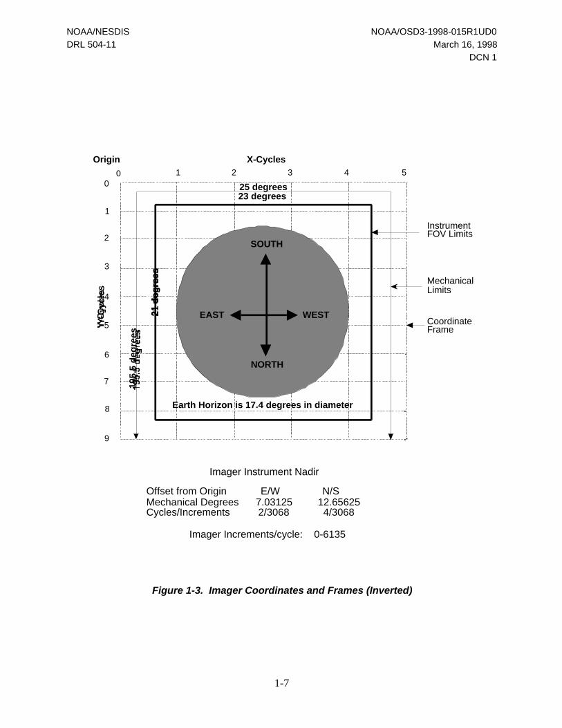
Figures 1-1 and 1-2 illustrate the cycles/increments coordinate system as related to the Imagerand Sounder fields of view for an upright spacecraft. The origin of the coordinate system is inthe upper left corner for the Imager and in the lower left corner for the Sounder. At a nominalgeosynchronous orbit, the Earth will be positioned within the frame as indicated. Under theseconditions, instrument nadir corresponds to the subsatellite point and has the coordinates denotedin the figure. The actual nadir values will vary somewhat according to the results of the factoryalignment. Figures 1-3 and 1-4 are the equivalent figures for an inverted spacecraft.
There are two inner boundaries within the coordinate system to consider. The first is themechanical scanning limits of the instrument, which are enforced via physical stops. The secondboundary is defined as the instrument’s operational field of view, or the planned scanning limits.Instrument scanning is performed within these bounds during normal operations. It is importantto note that due to the variation of the instrument nadir point, which is expected to be slightlydifferent for each instrument, the mechanical scanning limits will vary slightly with respect tothe origin of the cycles/increments coordinate system.
1.1.1.2 Line/Pixel Coordinate System
The line/pixel coordinate system was developed to provide GOES users with instrument scanposition information in a traditional graphics form. In this coordinate system, the east/west scanposition is described in pixels with the north/south scan position described in lines. The visiblechannel provides the basis for the line/pixel coordinate system for both instruments. Since a lineand pixel unit corresponds to the north/south and east/west angle swept by one visible detectorsample, line/pixel coordinates can be directly mapped to the received visible image arrays.
The line/pixel coordinate system is absolute: the calculation of these coordinates is performedwithout regard to the starting location of the frame. Different frame start locations are absolutelymapped to unique line/pixel coordinates, rather than mapping schemes in which coordinates aredefined relative to the start of each frame.
The origin of the line/pixel coordinate system is defined relative to that of the instrument (i.e.,scan mirror position) as a mapping of the northernmost visible detector in the visible detectorarray to the northwest corner of the instrument coordinate frame. The origin is not defined withrespect to the operational instrument field of view limits due to the variation of the actual

NOAA/NESDIS NOAA/OSD3-1998-015R1UD0
DRL 504-11 March 16, 1998
DCN 1
1-4
instrument nadir point from one instrument to another, which would cause the mapping to beinstrument unique rather than general for all instruments.
For the Imager, line/pixel reference locations are provided in the GVAR format for the imageframe corners, each image point, the current scan line number, and the easternmost andwesternmost visible pixel in the current scan. All of this data is contained in the Imagerdocumentation block (GVAR Block 0). For the Sounder, line/pixel coordinates are provided foreach pixel sampled in addition to the frame and scan line references previously described for theImager. Providing line/pixel coordinates for every Sounder sample is possible due to the farlower data rate of the Sounder as compared with the Imager.

NOAA/NESDIS NOAA/OSD3-1998-015R1UD0
DRL 504-11 March 16, 1998
DCN 1
1-5
00
1
1
2
2
3
3
4
4
5
5
6
7
8
9
NORTH
WEST EAST
SOUTH
23 degrees25 degrees
X-CyclesOrigin
Y-C
ycle
s
Earth Horizon is 17.4 degrees in diameter
InstrumentFOV Limits
MechanicalLimits
CoordinateFrame
Imager Instrument Nadir
Offset from Origin E/W N/SMechanical Degrees 7.03125 12.65625Cycles/Increments 2/3068 4/3068
Imager Increments/cycle: 0-6135
21 d
eg
rees
195.5
deg
rees
Figure 1-1. Imager Coordinates and Frames (Upright)

NOAA/NESDIS NOAA/OSD3-1998-015R1UD0
DRL 504-11 March 16, 1998
DCN 1
1-6
0
0
1
1
2
2
3
3
4
4
5
5
6
7
8
9
23 degrees
25 degrees
X-CyclesOrigin
Y-C
ycle
s
Earth Horizon is 17.4 degrees in diameterInstrumentFOV Limits
MechanicalLimits
CoordinateFrame
Sounder Instrument Nadir
Offset from Origin E/W N/SMechanical Degrees 7.03125 12.65625Cycles/Increments 2/1402 4/1402
Sounder Increments/Cycle: 0-2804
21 d
eg
rees
195.5
deg
rees
NORTH
WEST EAST
SOUTH
Figure 1-2. Sounder Coordinates and Frames (Upright)
NOAA/NESDIS NOAA/OSD3-1998-015R1UD0
DRL 504-11 March 16, 1998
DCN 1
1-7
00
1
1
2
2
3
3
4
4
5
5
6
7
8
9
SOUTH
EAST WEST
NORTH
23 degrees25 degrees
X-CyclesOrigin
Y-C
ycle
s
Earth Horizon is 17.4 degrees in diameter
InstrumentFOV Limits
MechanicalLimits
CoordinateFrame
Imager Instrument Nadir
Offset from Origin E/W N/SMechanical Degrees 7.03125 12.65625Cycles/Increments 2/3068 4/3068
Imager Increments/cycle: 0-6135
21 d
eg
rees
195.5
deg
rees
Figure 1-3. Imager Coordinates and Frames (Inverted)

NOAA/NESDIS NOAA/OSD3-1998-015R1UD0
DRL 504-11 March 16, 1998
DCN 1
1-8
0
0
1
1
2
2
3
3
4
4
5
5
6
7
8
9
23 degrees
25 degrees
X-CyclesOrigin
Y-C
ycle
s
Earth Horizon is 17.4 degrees in diameterInstrumentFOV Limits
MechanicalLimits
CoordinateFrame
Sounder Instrument Nadir
Offset from Origin E/W N/SMechanical Degrees 7.03125 12.65625Cycles/Increments 2/1402 4/1402
Sounder Increments/Cycle: 0-2804
21 d
eg
rees
195.5
deg
rees
SOUTH
EAST WEST
NORTH
Figure 1-4. Sounder Coordinates and Frames (Inverted)

NOAA/NESDIS NOAA/OSD3-1998-015R1UD0
DRL 504-11 March 16, 1998
DCN 1
1-9
1.1.2 Earth Location Processing
The GVAR format provides Earth location references to varying degrees for each instrument.For the Imager, the user is provided with the Earth locations expressed in latitude/longitudecoordinates for the northwest and southeast corners and the subsatellite point of the imagingframe. For the Sounder, the above references are provided along with the Earth locations of eachdetector sample (pixel) and the boresight (i.e., scan mirror position). In general, GOES userswould employ Earth location processes that allow the extraction of image areas within an Imagerframe which are bounded by predefined Earth locations. The process would not be necessary forthe Sounder, since both the location in the instrument and Earth frames are, respectively,provided in line/pixel and latitude/longitude coordinates. The Earth location process describedwould involve the determination of a line/pixel location given a latitude/longitude coordinate orvice versa. These processes are the inverse of one another and involve the determination of thespacecraft position and instrument attitude using the O&A coefficient set, which is provided inthe appropriate instrument’s documentation block. Prior to continuing with the description of thetransformation, an overview is provided in the following paragraphs of the Image MotionCompensation (IMC) process from an OGE operational point of view.
1.1.2.1 OGE Image Motion Compensation Processing
One of the most important features of the GOES I-M satellite system is the onboardcoregistration of image frames received over a specified time interval. The time interval isreferred to as the coregistration interval and is planned to be nominally 24 hours. Coregistrationof successive image frames involves both the OGE and the instruments operating in a closedloop fashion as described in the following paragraphs.
The process starts with the determination of the O&A over the specified coregistration interval.This is performed by the OGE’s Orbit and Attitude Tracking System (OATS). It results in theupload of an IMC coefficient set to the spacecraft containing estimates of the orbital state and theinstrument attitude, allowing the particular instrument’s scan mirror drive to compensate for thesatellite motion and instrument attitude variations. Each updated IMC set is determined fromstar measurements, known landmarks, and range data, previously provided by other OGEsubsystems.
In conjunction with the upload of the IMC coefficient set to the spacecraft, the O&A set is sentto the appropriate SPS for Earth location and gridding processing functions and for incorporationinto the GVAR format. The O&A coefficient set is a version of the IMC coefficient set whichhas been tailored for ground processing use. In general, the SPS implements the O&A set at thestart of the next image frame; therefore, if the update occurs in the middle of a frame, the currentset will continue to be used and reported in GVAR throughout the remainder of the frame. Thisprevents discontinuities in Earth location determination and gridding within a frame. It isimportant to note that if the O&A coefficient set is updated in the middle of a normal frame andthe frame is later interrupted by a priority frame, the current set is used throughout the normalframe with the updated set used throughout the priority frame.
NOAA/NESDIS NOAA/OSD3-1998-015R1UD0
DRL 504-11 March 16, 1998
DCN 1
1-10
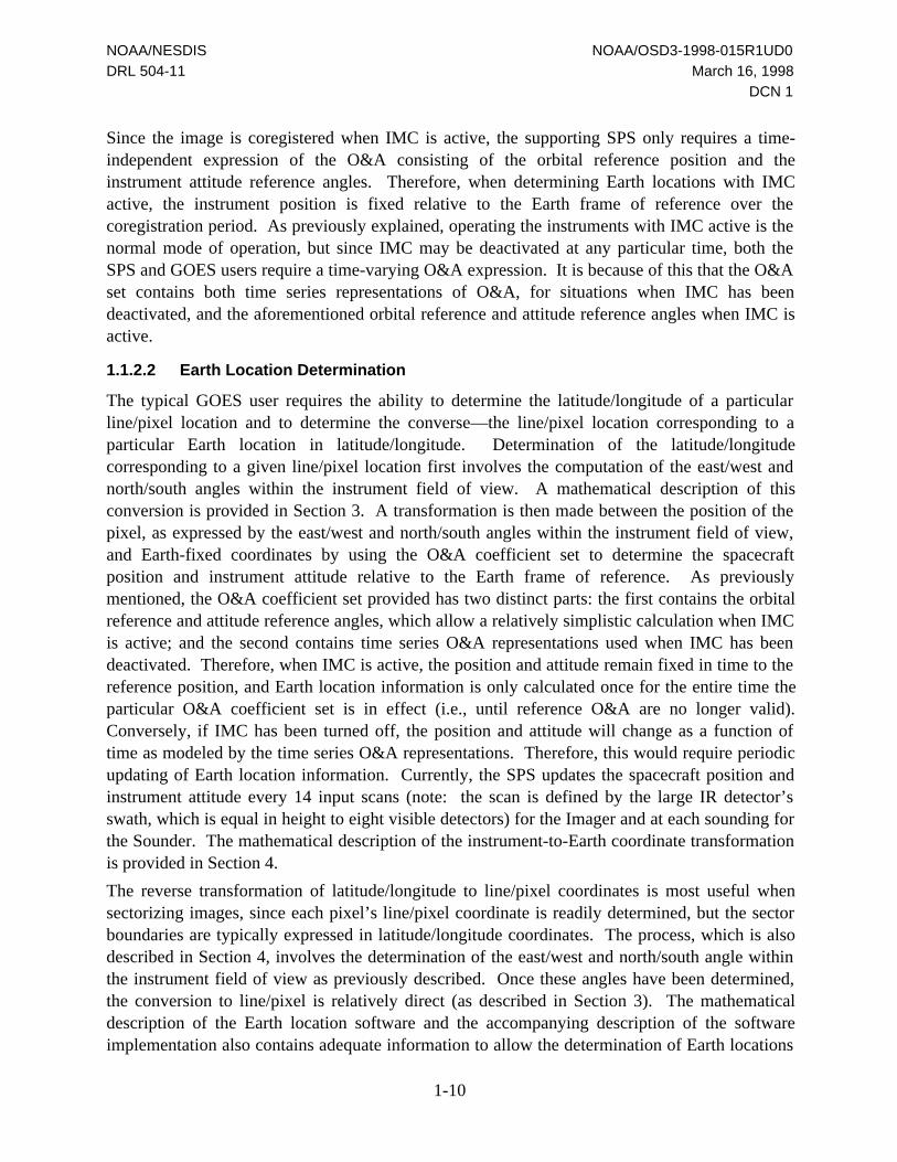
Since the image is coregistered when IMC is active, the supporting SPS only requires a time-independent expression of the O&A consisting of the orbital reference position and theinstrument attitude reference angles. Therefore, when determining Earth locations with IMCactive, the instrument position is fixed relative to the Earth frame of reference over thecoregistration period. As previously explained, operating the instruments with IMC active is thenormal mode of operation, but since IMC may be deactivated at any particular time, both theSPS and GOES users require a time-varying O&A expression. It is because of this that the O&Aset contains both time series representations of O&A, for situations when IMC has beendeactivated, and the aforementioned orbital reference and attitude reference angles when IMC isactive.
1.1.2.2 Earth Location Determination
The typical GOES user requires the ability to determine the latitude/longitude of a particularline/pixel location and to determine the converse—the line/pixel location corresponding to aparticular Earth location in latitude/longitude. Determination of the latitude/longitudecorresponding to a given line/pixel location first involves the computation of the east/west andnorth/south angles within the instrument field of view. A mathematical description of thisconversion is provided in Section 3. A transformation is then made between the position of thepixel, as expressed by the east/west and north/south angles within the instrument field of view,and Earth-fixed coordinates by using the O&A coefficient set to determine the spacecraftposition and instrument attitude relative to the Earth frame of reference. As previouslymentioned, the O&A coefficient set provided has two distinct parts: the first contains the orbitalreference and attitude reference angles, which allow a relatively simplistic calculation when IMCis active; and the second contains time series O&A representations used when IMC has beendeactivated. Therefore, when IMC is active, the position and attitude remain fixed in time to thereference position, and Earth location information is only calculated once for the entire time theparticular O&A coefficient set is in effect (i.e., until reference O&A are no longer valid).Conversely, if IMC has been turned off, the position and attitude will change as a function oftime as modeled by the time series O&A representations. Therefore, this would require periodicupdating of Earth location information. Currently, the SPS updates the spacecraft position andinstrument attitude every 14 input scans (note: the scan is defined by the large IR detector’sswath, which is equal in height to eight visible detectors) for the Imager and at each sounding forthe Sounder. The mathematical description of the instrument-to-Earth coordinate transformationis provided in Section 4.
The reverse transformation of latitude/longitude to line/pixel coordinates is most useful whensectorizing images, since each pixel’s line/pixel coordinate is readily determined, but the sectorboundaries are typically expressed in latitude/longitude coordinates. The process, which is alsodescribed in Section 4, involves the determination of the east/west and north/south angle withinthe instrument field of view as previously described. Once these angles have been determined,the conversion to line/pixel is relatively direct (as described in Section 3). The mathematicaldescription of the Earth location software and the accompanying description of the softwareimplementation also contains adequate information to allow the determination of Earth locations
NOAA/NESDIS NOAA/OSD3-1998-015R1UD0
DRL 504-11 March 16, 1998
DCN 1
1-11
from the instrument cycle/increment mirror position coordinates. This is the transformationperformed by the SPSs and is not expected to be undertaken by the majority of GOES users.Some additional explanation applies to this particular type of transformation. For the Imager,only the mirror position (i.e., scan addresses) of either end of each scan are reported.Determination of the mirror position within a scan is determined in the SPS by linearinterpolation. The reported mirror position is provided in the Imager documentation block(Block 0) as part of the header and trailer block reports. In the case of the Sounder, the mirrorposition of each dwell is reported, but the servo error value must be added to the mirror positionin cycles/increments prior to performing any transformations to determine the mirror’s trueposition. Since there are several servo error values reported with each dwell, one value has beenselected which best represents the true servo error contribution to the mirror position as seen inthe image data. This value is E-W scan servo error #8 which is contained in word #181 of theSounder raw data block. (Raw block contents included with each Sounder Sensor Block 11 aredescribed in the GVAR format specification.) In addition, the description and correspondingsoftware of the routine used to determine the Earth locations of the Sounder detectors is alsoprovided. Earth locating these detectors requires an additional correction for detector rotationwhich is a function of the north/south angle. Rotation correction is not necessary for the Imager,since it is performed by the instrument.
1.2 Document Organization
Section 2 of this document discusses the auxiliary GVAR data, Section 3 presents amathematical description of the instrument-related coordinate systems, and Section 4 describesthe transformations between the instrument and geographic coordinates. Module descriptionsand test cases are given in Sections 5 and 6, respectively.
The following three appendices are also provided:
• Appendix A—Example of OGE Earth location software usage
• Appendix B—OGE Earth location software listings
• Appendix C—Kamel-to-Keplerian transformation

NOAA/NESDIS NOAA/OSD3-1998-015R1UD0
DRL 504-11 March 16, 1998
DCN 1
2-1
2.0 Auxiliary GVAR Data
Besides the scan data, the GVAR stream contains additional information necessary for Earthlocation. This auxiliary data consists of the O&A coefficient set, the YAW FLIP flag, and thenadir offsets for each instrument. Each of these is discussed in this section.
2.1 Orbit and Attitude (O&A) Coefficient Set
This section provides a description of the form and content of the O&A coefficient set.Tables 2-1 and 2-2 define the format of the Imager and Sounder O&A coefficient sets as they aretransmitted in the GVAR format. The Imager O&A set is contained in the Imagerdocumentation block (Block 0) and the Sounder’s is included within the Sounder documentationBlock 11. Both tables have been extracted from the GVAR format description contained in theOGE Interface Specification (DRL 504-02). The word number references in the left column arethe actual word numbers of the data portion of the block (i.e., numbering does not include theheader portion). The functional content of both O&A coefficient sets is identical, so theircontent is described collectively in the following paragraphs in sequential order. Please note thatthe word references used in the description are the Imager’s (see Table 2-1 given at the end ofSection 2.1.1).
2.1.1 O&A Format Description
At the start of each O&A coefficient set, an IMC set identifier is provided. Each set has a uniqueASCII identifier enabling users to discriminate changes in O&A coefficient sets. The format ofthe IMC set identifier is described in Section 4.3.1.1 of the OGE Interface Specification(DRL 504-02).
The next seven parameters (words 295 through 322) provide the O&A position references whichare used when IMC is active. The first four parameters are orbital position references with theremaining three being the roll, pitch, and yaw reference angles. The roll and pitch misalignmentangles are totally compensated when IMC is active and, therefore, references for these angles arenot required. The reference O&A parameters are then followed by the epoch date and time ofthe O&A set, which is the set’s reference time. In other words, the epoch time defines T = 0 forthe O&A coefficient set and is used only when IMC is off to time reference the O&A time seriesequations. The recommended IMC set enable time from epoch (words 331–334) is the timewhen the IMC set is nominally activated on the spacecraft.
The spacecraft compensation parameters (words 335 to 346) provide the capability to apply thesame correction bias to the Imager and Sounder due to spacecraft disturbance that may occurduring the coregistration period.
NOAA/NESDIS NOAA/OSD3-1998-015R1UD0
DRL 504-11 March 16, 1998
DCN 1
2-2
Following the spacecraft compensation parameters are the coefficients for the orbital time seriesused for calculating the spacecraft position when IMC is off. The functional form of the timeseries is described in Section 4.1.
The remainder of the O&A coefficient set consists of the exponential start time from epochwhich is followed by the time series expressions describing the instrument attitude variation ofthe five attitude angles—roll, pitch, yaw, roll misalignment, and pitch misalignment. The rolland pitch misalignment angles define the misalignment of the instrument optical axis and areincorporated as corrections to the instrument elevation and scan angles. Each angle’s time seriesequation has the same functional form consisting of exponential, Fourier, and monomial sinusoidfunctional components. Since the exponential component is not normally in use, the exponentialstart time is provided to define when it should be activated as part of the time series computation.It is expressed as a delta time from epoch and should be positive. The Fourier and the monomialsinusoid components are expressed as a series containing a variable number of these functions.The format of the associated word fields allows for the maximum number of each of thefunctions expected. The number of Fourier and monomial sinusoid coefficients that areapplicable in a particular O&A coefficient set is respectively defined in words 535 to 538 andwords 659 to 662. The practical maximums are currently expected to be 15 Fourier and 4monomial sinusoids.
Table 2-1 provides the O&A parameters in use for the Imager instrument. The format andengineering units of each variable are denoted in parentheses. The partition is sized to hold thelargest expected O&A set. In general, the actual number of parameters in effect is less than themaximum and varies through time. The “numeric” parameters (words 535–538 and 659–662)are used to denote the number of active terms employed for the roll attitude angle. In a similarfashion, each of the remaining four angles modeled by the O&A set is provided with “numeric”parameters defining the number of active terms. Inactive terms are not compressed out of theO&A set; their places are occupied by zeroed data words.
Table 2-2 provides the O&A parameters in use for the Sounder instrument. The format andengineering units of each variable are denoted in parentheses. The partition is sized to hold thelargest expected O&A set. In general, the actual number of parameters in effect is less than themaximum and varies through time. The “number” parameters (words 563–566 and 687–690) areused to denote the number of active terms employed for the roll attitude angle. In a similarfashion, each of the remaining four angles modeled by the O&A set is provided with “numeric”parameters defining the number of active terms. Inactive terms are not compressed out of theO&A set; their places are occupied by zeroed data words.

NOAA/NESDIS NOAA/OSD3-1998-015R1UD0
DRL 504-11 March 16, 1998
DCN 1
2-3
Table 2-1. Imager Documentation Block 0 Format Definition (1 of 2)
Words Description (Format, Units)
279–282 IMC Set Identifier (I*16, 4 ASCII characters)
283–294 Spares – not used
295–298 Reference longitude (R*4, rad), positive east
299–302 Reference radial distance from nominal (R*4, km)
303–306 Reference latitude (R*4, rad)
307–310 Reference orbit yaw (R*4, rad)
311–314 Reference attitude: roll (R*4, rad)
315–318 Reference attitude: pitch (R*4, rad)
319–322 Reference attitude: yaw (R*4, rad)
323–330 Epoch date/time: standard BCD format
331–334 IMC set enable time from epoch (R*4, min)
335–338 Spacecraft compensation: roll (R*4, rad)
339–342 Spacecraft compensation: pitch (R*4, rad)
343–346 Spacecraft compensation: yaw (R*4, rad)
347–398 Change in longitude from ref. (13@R*4, rad), positive east
399–442 Change in radial distance from ref. (11 @ R*4, km)
443–478 Sine geocentric latitude, total (9 @ R*4, no units)
479–514 Sine orbit yaw, total (9 @ R*4, no units)
515–518 Daily solar rate (R*4, rad/min)
519–522 Exponential start time from epoch (R*4, min)
Words 523–742 apply to roll attitude angle
523–526 Exponential magnitude (R*4, rad)
527–530 Exponential time constant (R*4, min)
531–534 Constant, mean attitude angle (R*4, rad)
535–538 Number of sinusiods/angles (I*4, no units)
539–542 Magnitude of first-order sinusoid(R*4, rad)
543–546 Phase angle of first-order sinusoid (R*4, rad)
M M
651–654 Magnitude of fifteenth sinusoid (R*4, rad)
655–658 Phase angle of fifteenth sinusoid (R*4, rad)

NOAA/NESDIS NOAA/OSD3-1998-015R1UD0
DRL 504-11 March 16, 1998
DCN 1
2-4
Table 2-1. Imager Documentation Block 0 Format Definition (2 of 2)
Words Description (Format, Units)
659–662 Number of monomial sinusiods (I*4, no units)
663-666 Order of applicable sinusoid (I*4, no units)
667–670 Order of first monomial sinusoid (I*4, no units)
671–674 Magnitude of monomial sinusoid (R*4, rad)
675–678 Phase angle of monomial sinusoid (R*4, rad)
679–682 Angle from epoch where monomial is zero (R*4, rad)
683–702 Repeat of 663–682 but for second monomial
703–722 Repeat of 663–682 but for third monomial
723–742 Repeat of 663–682 but for fourth monomial
743–962 Repeat of 523–742 for pitch attitude angle
963–1182 Repeat of 523–742 for yaw attitude angle
1183–1402 Repeat of 523–742 for roll misalignment angle
1403–1622 Repeat of 523–742 for pitch misalignment angle
1623–1689 Spares – unused
1690 Longitudinal parity (XOR) of words 279–1689

NOAA/NESDIS NOAA/OSD3-1998-015R1UD0
DRL 504-11 March 16, 1998
DCN 1
2-5
Table 2-2. Sounder Instrument Documentation Block (1 of 2)
Words Description (Format, Units)
307–310 IMC set identifier (I*16, 4 ASCII characters)
311–322 Spares – not used
323–326 Reference longitude (R*4, rad), positive east
327–330 Reference radial distance from nominal (R*4, km)
331–334 Reference latitude (R*4, rad)
335–338 Reference orbit yaw (R*4, rad)
339–342 Reference attitude: roll (R*4, rad)
343–346 Reference attitude: pitch (R*4, rad)
347–350 Reference attitude: yaw (R*4, rad)
351–358 Epoch date/time: standard BCD format
359–362 IMC set enable time from epoch (R*4, min)
363–366 Spacecraft compensation: roll (R*4, rad)
367–370 Spacecraft compensation: pitch (R*4, rad)
371–374 Spacecraft compensation: yaw (R*4, rad)
375–426 Change in longitude from ref. (13 @ R*4, rad), positive east
427–470 Change in radial distance from ref. (11 @ R*4, km)
471–506 Sine geocentric latitude, total (9 @ R*4, no units)
507–542 Sine orbit yaw, total (9 @ R*4, no units)
543–546 Daily solar rate (R*4, rad/min)
547–550 Exponential start time from epoch (R*4, min)
Words 551–770 apply to roll attitude angle
551–554 Exponential magnitude (R*4, rad)
555–558 Exponential time constant (R*4, min)
559–562 Constant, mean attitude angle (R*4, rad)
563–566 Number of sinusiods/angles (I*4, no units)
567–570 Magnitude of first-order sinusoid (R*4, rad)
571–574 Phase angle of first-order sinusoid (R*4, rad)
M M
679–682 Magnitude of fifteenth sinusoid (R*4, rad)
683–686 Phase angle of fifteenth sinusoid (R*4, rad)
NOAA/NESDIS NOAA/OSD3-1998-015R1UD0
DRL 504-11 March 16, 1998
DCN 1
2-6
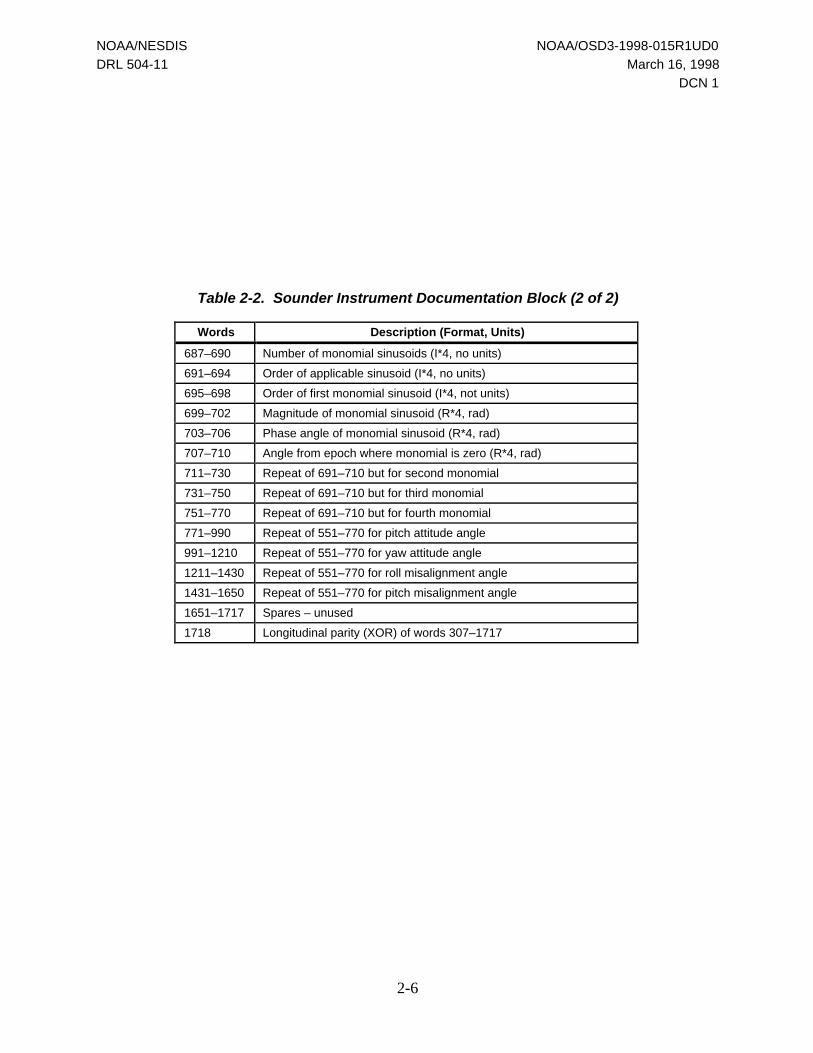
Table 2-2. Sounder Instrument Documentation Block (2 of 2)
Words Description (Format, Units)
687–690 Number of monomial sinusoids (I*4, no units)
691–694 Order of applicable sinusoid (I*4, no units)
695–698 Order of first monomial sinusoid (I*4, not units)
699–702 Magnitude of monomial sinusoid (R*4, rad)
703–706 Phase angle of monomial sinusoid (R*4, rad)
707–710 Angle from epoch where monomial is zero (R*4, rad)
711–730 Repeat of 691–710 but for second monomial
731–750 Repeat of 691–710 but for third monomial
751–770 Repeat of 691–710 but for fourth monomial
771–990 Repeat of 551–770 for pitch attitude angle
991–1210 Repeat of 551–770 for yaw attitude angle
1211–1430 Repeat of 551–770 for roll misalignment angle
1431–1650 Repeat of 551–770 for pitch misalignment angle
1651–1717 Spares – unused
1718 Longitudinal parity (XOR) of words 307–1717
NOAA/NESDIS NOAA/OSD3-1998-015R1UD0
DRL 504-11 March 16, 1998
DCN 1
2-7
2.1.2 Notation Conversion
The notation used in Section 4 when describing the functional form of the equations associatedwith the O&A coefficients can be directly mapped to the word location using the followingequations:
1. a(i) = X + (i – 1) * 4
where X is the starting word location of the O&A coefficient set,
X = 279 (Imager) or 307 (Sounder)
a(i) maps to the value located at word position x + (I – 1) * 4
2. C(j) = a(k + j – 1)
where a(k) corresponds to the word location of the C(1) coefficient.
Definition of C(1) varies with respect to the particular attitude angle as described inSection 4.3.
2.2 Yaw Flip Flag
As discussed earlier, the misalignment model takes different forms for normal and flippedspacecraft, as well as for different instruments. Therefore, it is necessary to transmit in theGVAR data stream a flag denoting the spacecraft configuration. Block 0 contains the yaw-flipflag in bit 16 of ISCAN; it is equal to 0 for normal operations or 1 for flipped operations. AllBlock 11 messages contain the yaw-flip flag in the SAD ID word 20. It has the value x ‘00’ fornormal operations or the value x ‘3F’ for flipped operations. The Sounder Scan DocumentationBlock 11 has the yaw-flip flag in bit 0 of word 57, with 0 for normal operations or 1 for flippedoperations.
It is the responsibility of the user’s software to store this flag in such a way that the ELUGroutines can use it.
2.3 Nadir Offset
Ideally each instrument points at the subsatellite point (nadir) when the mirror is centered in theinstrument field of view. In general, this is not the case. To accommodate hardware limitations,nadir offset parameters were introduced. All O&A sets use these values, which are transmittedin GVAR, as a reference. Earth location requires knowledge of these parameters. The values area combination of the measured instrument deviation from ideal, Earth sensor pitch biases, andother biases that may have been introduced into the system. All of these are reflected in thenumbers reported by the SPS in GVAR. Although not often, these numbers change if thecontrolling Earth sensor is changed or if other biases are introduced into the system. The ELUGroutine SETCONS uses these values to calculate ELVMAX and SCNMAX for each instrument.

NOAA/NESDIS NOAA/OSD3-1998-015R1UD0
DRL 504-11 March 16, 1998
DCN 1
2-8
(Section 3.3 gives a more detailed discussion of ELVMAX and SCNMAX.) SETCONS (or itsequivalent) should be called anytime the instrument nadir values change.
NOAA/NESDIS NOAA/OSD3-1998-015R1UD0
DRL 504-11 March 16, 1998
DCN 1
3-1
3.0 Mathematical Description of Instrument-RelatedCoordinate Systems
This section describes instrument-related coordinate systems used in the Earth location processand the algorithms used to perform the necessary coordinate conversions.
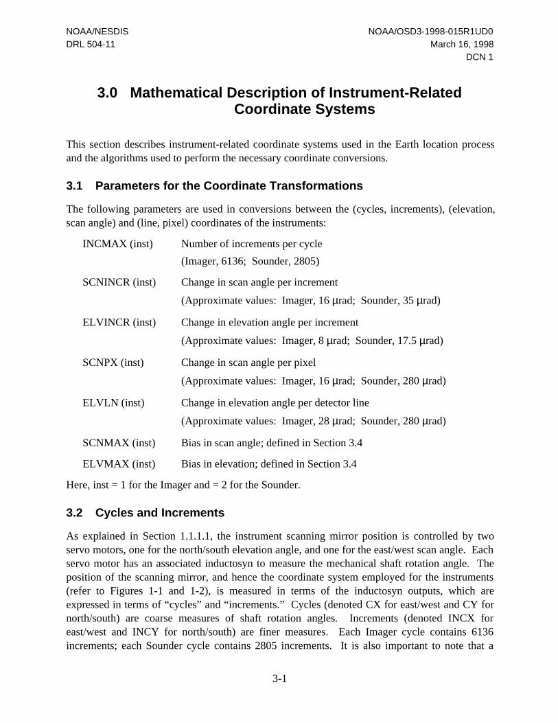
3.1 Parameters for the Coordinate Transformations
The following parameters are used in conversions between the (cycles, increments), (elevation,scan angle) and (line, pixel) coordinates of the instruments:
INCMAX (inst) Number of increments per cycle
(Imager, 6136; Sounder, 2805)
SCNINCR (inst) Change in scan angle per increment
(Approximate values: Imager, 16 µrad; Sounder, 35 µrad)
ELVINCR (inst) Change in elevation angle per increment
(Approximate values: Imager, 8 µrad; Sounder, 17.5 µrad)
SCNPX (inst) Change in scan angle per pixel
(Approximate values: Imager, 16 µrad; Sounder, 280 µrad)
ELVLN (inst) Change in elevation angle per detector line
(Approximate values: Imager, 28 µrad; Sounder, 280 µrad)
SCNMAX (inst) Bias in scan angle; defined in Section 3.4
ELVMAX (inst) Bias in elevation; defined in Section 3.4
Here, inst = 1 for the Imager and = 2 for the Sounder.
3.2 Cycles and Increments
As explained in Section 1.1.1.1, the instrument scanning mirror position is controlled by twoservo motors, one for the north/south elevation angle, and one for the east/west scan angle. Eachservo motor has an associated inductosyn to measure the mechanical shaft rotation angle. Theposition of the scanning mirror, and hence the coordinate system employed for the instruments(refer to Figures 1-1 and 1-2), is measured in terms of the inductosyn outputs, which areexpressed in terms of “cycles” and “increments.” Cycles (denoted CX for east/west and CY fornorth/south) are coarse measures of shaft rotation angles. Increments (denoted INCX foreast/west and INCY for north/south) are finer measures. Each Imager cycle contains 6136increments; each Sounder cycle contains 2805 increments. It is also important to note that a
NOAA/NESDIS NOAA/OSD3-1998-015R1UD0
DRL 504-11 March 16, 1998
DCN 1
3-2
shaft angle change in the east/west direction has a doubling effect upon the mirror’s opticalangle.
The origin of the coordinate system (zero cycles, zero increments) corresponds to the northwestcorner of the Imager’s field of view for normal operations and the southeast corner for invertedoperations. For the Sounder, the origin is in the southwest corner in the Sounder’s field of viewfor normal operations and the northeast corner for inverted operations. The instruments’mechanical limits are enforced by the presence of physical stops
3.3 Lines and Pixels
As previously described in Section 1.1.1.2, the mapping scheme which translates instrumentcycles/increments coordinates to line/pixel coordinates was designed to cover the entireinstrument coordinate frame. Therefore, the area covered by the line/pixel coordinate system canbe directly superimposed over the instrument coordinate frame which covers 9 cycles in thenorth/south dimension and 5 cycles in the east/west dimension. This scheme was chosen toprovide a mapping that is instrument independent. The mapping would not be instrumentindependent if the line/pixel coordinate system only covered the area defined by the operationallimits (instrument field of view, refer to Figures 1-1 and 1-2). The instrument dependence wouldbe caused by the variation of the actual nadir location between versions of the Imager or Sounderinstruments.
A line and pixel unit, respectively, corresponds to the north/south and east/west angles swept byone visible pixel. Therefore, the mapping can be visualized as the division of the Imager andSounder coordinate frame into visible detector lines in the north/south direction and pixel units inthe east/west direction. The origin of the line and pixel coordinate system is at the northwestcorner of the instrument coordinate system for both the Imager and the Sounder and is defined asline #1, pixel #1, where
• Line #1 corresponds to the northernmost visible detector line possible, which is located atthe extreme northernmost elevation angle in the instrument coordinate frame. Linenumbers increase in the southerly direction.
• Pixel #1 corresponds to the extreme western position of the instrument’s coordinatesystem. Pixel numbers increase in the easterly direction.
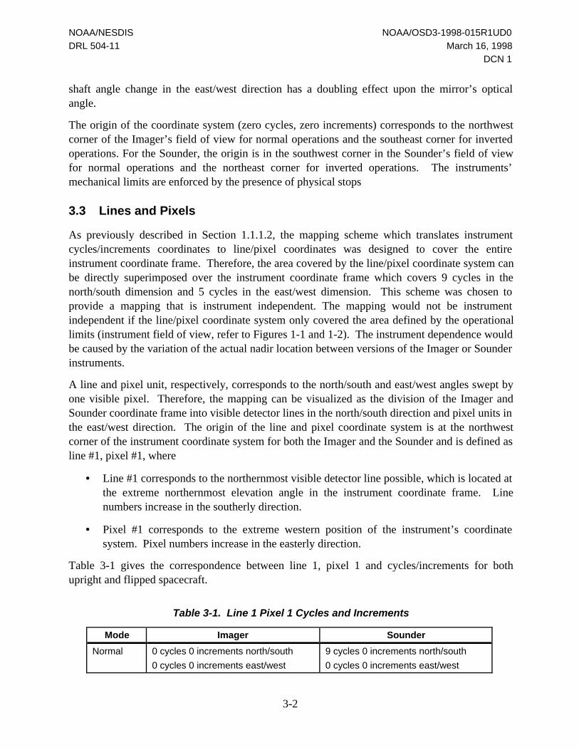
Table 3-1 gives the correspondence between line 1, pixel 1 and cycles/increments for bothupright and flipped spacecraft.
Table 3-1. Line 1 Pixel 1 Cycles and Increments
Mode Imager Sounder
Normal 0 cycles 0 increments north/south
0 cycles 0 increments east/west
9 cycles 0 increments north/south
0 cycles 0 increments east/west

NOAA/NESDIS NOAA/OSD3-1998-015R1UD0
DRL 504-11 March 16, 1998
DCN 1
3-3
Inverted 9 cycles 0 increments north/south
5 cycles 0 increments east/west
0 cycles 0 increments north/south
5 cycles 0 increments east/west
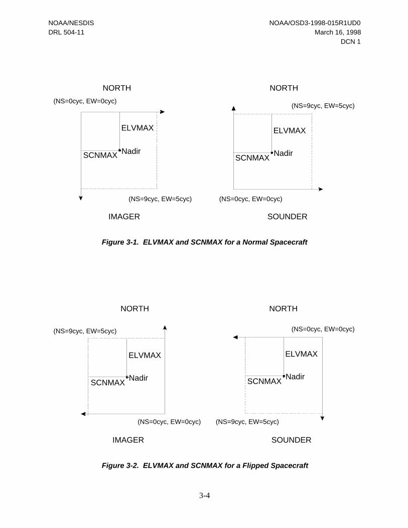
3.4 Elevation and Scan Angles
Zero elevation and zero scan angles correspond to the instrument pointing at the subsatellitepoint (nadir). Therefore, the origin of the elevation-and-scan-angle coordinate system is biasedrelative to the origin of the cycles/increments coordinate system. The east/west bias is denotedas SCNMAX, and the north/south bias is denoted as ELVMAX. Their values are supposed tocorrespond to 4 cycles, 3068 increments north/south and 2 cycles, 3068 increments east/west forthe Imager; and to 4 cycles, 1402 increments north/south and 2 cycles, 1402 increments east/westfor the Sounder. The actual values are derived from the factory-measured nadir location of theinstrument, expressed in north/south and east/west cycles and increments and are provided,respectively, in the Imager documentation Block 0 (words 6305–6310) and the Sounderdocumentation Block 11 (words 3005–3010).
For all spacecraft, normal and flipped, the elevation angle decreases from north to south and thescan angle increases from west to east. This means that the transformation fromcycles/increments coordinates to elevation-and-scan-angle coordinates depends upon thespacecraft orientation.
For a normal spacecraft, ELVMAX and SCNMAX are defined as the offset from the northwestcorner of the instrument as shown in Figure 3-1. Because the elevation/scan angle coordinatesare an Earth-based system, ELVMAX and SCNMAX are kept as the offsets from the northwestcorner of the instrument for flipped spacecraft as shown in Figure 3-2. Using the nadir locationsdistributed in GVAR of NSCYC1/NSINC1 and EWCYC1/EWINC1 for the Imager andNSCYC2/NSINC2 and EWCYC2/EWINC2 for the Sounder, the following equations give thevalue of ELVMAX and SCNMAX:
ELVMAX(1) = ELVINCR(1) * [NSCYC1*INCMAX(1) + NSINC1]
SCNMAX(1) = SCNINCR(1) * [EWCYC1*INCMAX(1) + EWINC1]
ELVMAX(2) = ELVINCR(2) * [(9 – NSCYC2)*INCMAX(2) – NSINC2]
SCNMAX(2) = SNCINCR(2) * [EWCYC2*INCMAX(2) + EWINC2]
For a flipped spacecraft, the SPS will distribute nadir values in GVAR such that the abovedefinitions will compute the correct values for ELVMAX and SCNMAX.
Users must, however, recalculate ELVMAX and SCNMAX if the nadir locations change.
NOAA/NESDIS NOAA/OSD3-1998-015R1UD0
DRL 504-11 March 16, 1998
DCN 1
3-4
IMAGER SOUNDER
Nadir
ELVMAX
SCNMAX Nadir
ELVMAX
SCNMAX
NORTH NORTH
(NS=9cyc, EW=5cyc)
(NS=0cyc, EW=0cyc)
(NS=0cyc, EW=0cyc)
(NS=9cyc, EW=5cyc)
Figure 3-1. ELVMAX and SCNMAX for a Normal Spacecraft
IMAGER SOUNDER
Nadir
ELVMAX
SCNMAXNadir
ELVMAX
SCNMAX
NORTHNORTH
(NS=0cyc, EW=0cyc)
(NS=0cyc, EW=0cyc)
(NS=9cyc, EW=5cyc)
(NS=9cyc, EW=5cyc)
Figure 3-2. ELVMAX and SCNMAX for a Flipped Spacecraft

NOAA/NESDIS NOAA/OSD3-1998-015R1UD0
DRL 504-11 March 16, 1998
DCN 1
3-5
3.5 Notes on the Instrument-Related Coordinate Systems
Cycles/increments coordinates define the north/south and east/west positions of the instrumentscanning mirror, that is, the direction of its optical axis. Cycles/increments coordinates areinconvenient for describing the pointing of the instruments’ individual detectors which arealways biased relative to the optical axis.
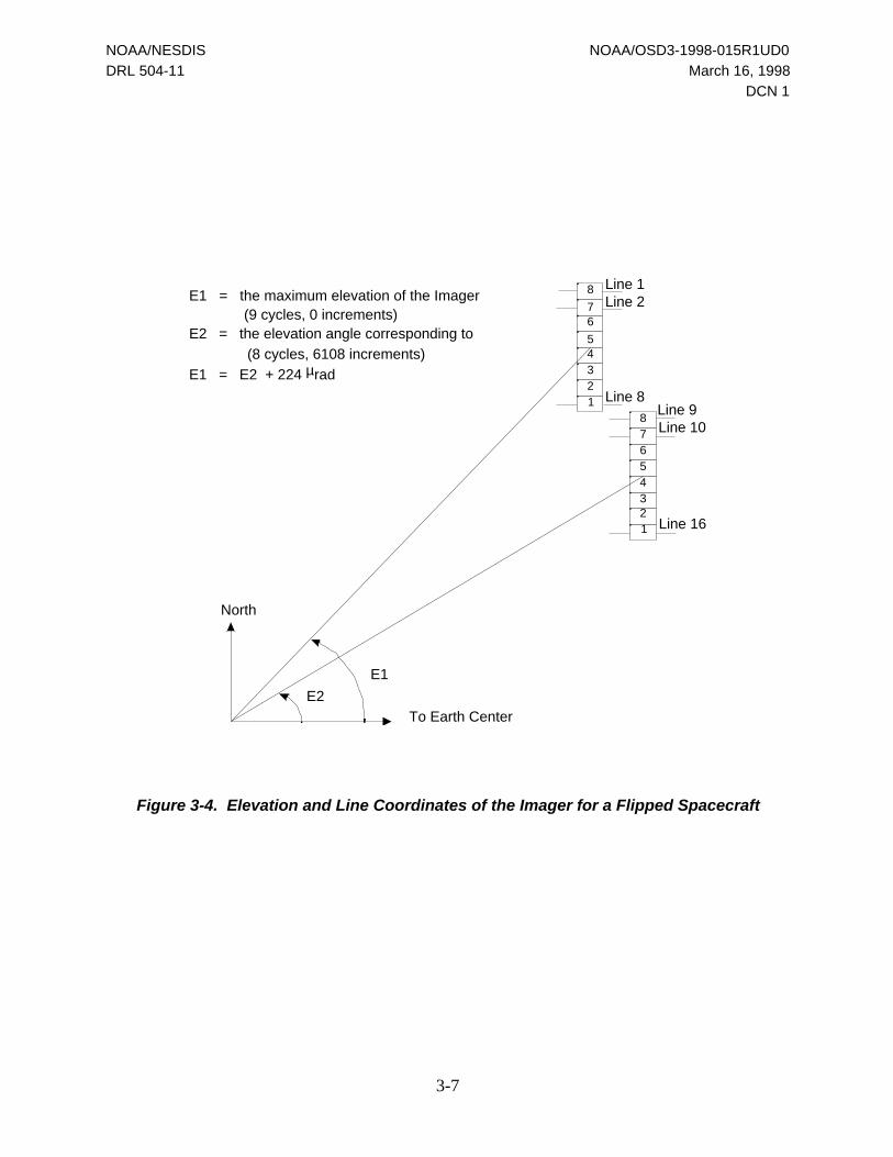
Lines and pixels are defined as coordinates of the uniformly spaced grid covering theinstrument’s field of view. The northernmost line of the grid, line #1, corresponds to the linedrawn by the uppermost detector when the optical axis of the instrument has the maximumpossible elevation. The relation between the line and elevation coordinates for the Imager VISchannel is shown in Figure 3-3 for a normal spacecraft and in Figure 3-4 for a flipped spacecraft.
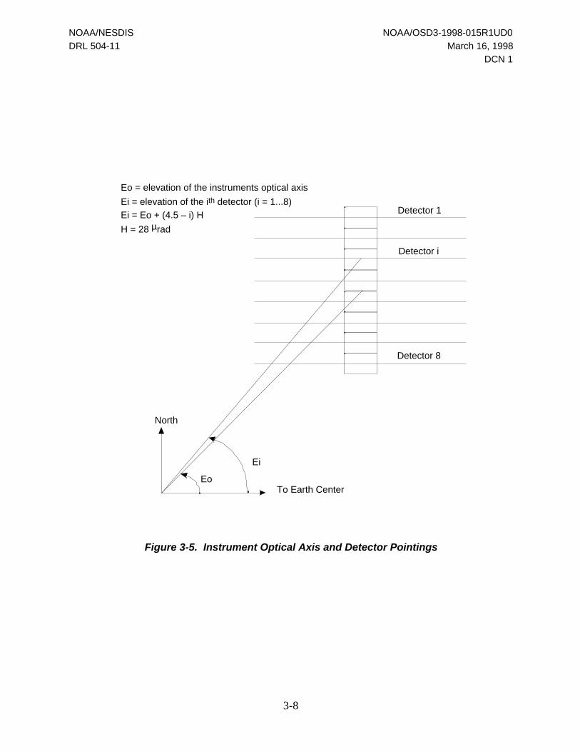
For the Imager VIS channel, the elevation angle related to line #1 is a sum of ELVMAX(instrument pointing) and 3.5 detector heights [uppermost detector pointing with respect to theoptical axis of the instrument (see Figure 3-5 for the Imager VIS channel of a normalspacecraft)]. The corresponding formula is given in Section 3.7. The above also implies that,for the Imager VIS channel, the elevation angles related to the first four visible lines are alwaysgreater than ELVMAX.
Similarly, pixel #1 (westernmost pixel) corresponds to the extreme western position of theinstrument’s optical axis. The magnitude of the related scan angle is denoted as SCNMAX.
The relationship between lines/pixels and elevation/scan angles depends on the nadir offset ofeach instrument. Like the elevation/scan angle coordinates, the line/pixel coordinates areabsolute—they are independent of a particular image frame, which is defined by thecycle/increment coordinates of the frame corners. Correspondingly, the lines and pixels shouldnot be confused with the images of individual detectors. Due to the instrument’s mechanicallimits, an actual image frame never contains points with line = 1 or pixel = 1 coordinates.

NOAA/NESDIS NOAA/OSD3-1998-015R1UD0
DRL 504-11 March 16, 1998
DCN 1
3-6
Figure 3-3. Elevation and Line Coordinates of the Imager for a Normal Spacecraft
NOAA/NESDIS NOAA/OSD3-1998-015R1UD0
DRL 504-11 March 16, 1998
DCN 1
3-7
5
8
76
4321
Line 1Line 2
Line 8
8765432
Line 9Line 10
Line 16
To Earth Center
North
E2
E1
E1 = the maximum elevation of the Imager(9 cycles, 0 increments)
E2 = the elevation angle corresponding to
(8 cycles, 6108 increments)
E1 = E2 + 224 µrad
1
Figure 3-4. Elevation and Line Coordinates of the Imager for a Flipped Spacecraft
NOAA/NESDIS NOAA/OSD3-1998-015R1UD0
DRL 504-11 March 16, 1998
DCN 1
3-8
To Earth Center
North
Eo
Ei
Detector 1
Detector i
Detector 8
Eo = elevation of the instruments optical axis
Ei = elevation of the ith detector (i = 1...8)
Ei = Eo + (4.5 – i) H
H = 28 µrad
Figure 3-5. Instrument Optical Axis and Detector Pointings

NOAA/NESDIS NOAA/OSD3-1998-015R1UD0
DRL 504-11 March 16, 1998
DCN 1
3-9
3.6 Cycles/Increments to Elevation and Scan Angles Conversion
With the elevation/scan angle coordinate system being Earth-fixed, the transformations forcycles/increments differs for normal and flipped spacecraft.
For a normal spacecraft, the transformation from the north/south cycles and increments(CY,INCY) to the instrument scanning mirror elevation angle, EV, is defined as
EV = ELVMAX(1) – ELVINCR(1)*[CY*INCMAX(1) + INCY]
EV = ELVMAX(2) – ELVINCR(2)*[(9-CY)*INCMAX(2) – INCY]
and the transformation from east/west cycles and increments (CX, INCX) to the mirror scanangle, SC, is
SC = SCNINCR(inst)*[CX*INCMAX(inst) + INCX] – SCNMAX (inst)
For a flipped spacecraft, the transformation from the north/south cycles and increments(CY,INCY) to the instrument scanning mirror elevation angle, EV, is defined as
EV = ELVMAX(1) – ELVINCR(1)*[(9–CY)*INCMAX(1) – INCY]
EV = ELVMAX(2) – ELVINCR(2)*[CY*INCMAX(2) + INCY]
and the transformation from east/west cycles and increments (CX, INCX) to the mirror scanangle, SC, is
SC = SCNINCR(inst)*[(5–CX)*INCMAX(inst) – INCX] - SCNMAX (inst)
where inst = 1 for the Imager and = 2 for the Sounder.
3.7 Line/Pixel to Elevation/Scan Angle Conversion
For a given instrument, the elevation angle, EV, is computed from the line number, LINE, as
EV = ELVMAX(inst) + (D – LINE) * ELVLN(inst)
where D is the elevation of the northernmost detector relative to the optical axis of theinstrument, expressed in detector lines. For the Imager, D = 4.5; for the Sounder, D = 2.5. Thescan angle, SC, is computed from the pixel number, PIXEL, as
SC = (PIXEL – 1) * SCNPX(inst) – SCNMAX(inst)
Correspondingly, the transformations from elevation and scan angles to line and pixelcoordinates are written as
LINE = [ELVMAX(inst) – EV]/ELVLN(inst) + D
PIXEL = [SCNMAX(inst) + SC]/SCNPX(inst) + 1
NOAA/NESDIS NOAA/OSD3-1998-015R1UD0
DRL 504-11 March 16, 1998
DCN 1
3-10
3.8 Optical Axis Correction
When transforming cycles and increments or lines and pixels to/from elevation and scan angles,OATS includes an additional optical axis correction term that was not included in the ELUGequations. This correction is applied as the final step in converting to elevation and scan anglesand is applied as the first step in converting from elevation and scan angles. When convertingcycles and increments to/from lines and pixels via the elevation and scan angles, these termscancel. They are only relevant for cycles and increments or line and pixel conversions to/fromlatitude and longitude. To minimize the changes in the ELUG software, this correction has beenadded to the routines LPOINT and GPOINT. When converting from latitude and longitude, theangles EV' and SC' need to be corrected by the following equations:
EV = EV' + EV'*SC' * (SCNMAX(INSTR) – 2.5*INCMAX(INSTR) * SCNINCR(INSTR))
SC = SC' – EV'2 * (SCNMAX(INSTR) – 2.5*INCMAX(INSTR) * SCNINCR(INSTR))/2
When converting from angles EV' and SC' to latitude and longitude, the following correctionsneed to be applied:
EV = EV' – EV' * SC' * (SCNMAX(INSTR) – 2.5*INCMAX(INSTR) * SCNINCR(INSTR))
SC = SC' + EV'2 * (SCNMAX(INSTR) – 2.5*INCMAX(INSTR) * SCNINCR(INSTR))/2

NOAA/NESDIS NOAA/OSD3-1998-015R1UD0
DRL 504-11 March 16, 1998
DCN 1
4-1
4.0 Transformations Between the Instrument andGeographic Coordinates
4.1 Orbit Model
The satellite position is described by four states (see Appendix C for definition and relationshipto Keplerian elements): the longitude (LAM), the radial distance (R), the geocentric latitude(PHI), and the orbit yaw (PSI). Their values are computed from a set of 336 O&A coefficients inGVAR Block 0. These O&A coefficients are denoted as a1, a2, a3, … , a335, a336.
If IMC is enabled, LAM = a5, R = 42164.17478 + a6, PHI = a7, and PSI = a8. Nominally,a5 = station longitude (positive east) and a6 = a7 = a8 = 0.
If IMC is disabled, the orbit is described by 42 coefficients that are used to determine four time-dependent values that give the current orbit state. The four quantities are the sine of the orbityaw (DYAW), the change in the radial distance from the reference orbit radius (DR), the sine ofthe geocentric latitude (DLAT), and the change in the longitude (DLON). The correspondingformulas are as follows:
DLON = a18 + a19*A + a20*A2 + 2 * [a21*sin(A) + a22*cos(A)
+ a23*sin(2*A) + a24*cos(2*A) + a25*sin(1.9268*A)
+ a26*cos(1.9268*A) + a27*sin(0.927*A)
+ a28*cos(0.927*A)] + 2*A*[a29*sin(A) + a30*cos(A)]
DR = a31 + a32*cos(A) + a33*sin(A) + a34*cos(2*A)
+ a35*sin(2*A) + a36*cos(1.9268*A) + a37*sin(1.9268*A)
+ a38*cos(0.927*A) + a39*sin(0.927*A)
+ A * [a40*cos(A) + a41*sin(A)]
DLAT = a42 + a43*cos(A) + a44*sin(A) + a45*cos(2*A)
+ a46*sin(2*A) + A * [a47*cos(A) + a48*sin(A)]
+ a49*cos(0.927*A) + a50*sin(0.927*A)
DYAW = a51 + a52*sin(A) + a53*cos(A) + a54*sin(2*A)
+ a55*cos(2*A) + A*[a56*sin(A) + a57*cos(A)]
+ a58*sin(0.927*A) + a59*cos(0.927*A)

NOAA/NESDIS NOAA/OSD3-1998-015R1UD0
DRL 504-11 March 16, 1998
DCN 1
4-2
Here A = 0.7292115E–4 * T and T = time in seconds since epoch. If IMC is disabled,
LAM = a5 + DLON
R = 42164.17478 + DR
PHI = arcsin(DLAT)
PSI = arcsin(DYAW)
In the next step, the IMC longitude, the geocentric latitude, and the orbit yaw are converted tothe orbit inclination (i), the argument of latitude (u), and the longitude of the ascending node(ASC):
i = arcsin{[sin2(PHI) + sin2(PSI)]1/2}
u = arctan[sin(PHI)/sin(PSI)]
ASC = LAM – u
The related subsatellite longitude and geodetic latitude are given by
RLON = ASC + arctan[cos(i)*sin(u)/cos(u)]
RLAT = arctan[tan(PHI)/(1 – F)2]
where F is the Earth flattening factor.
All these computations are performed by the LMODEL subroutine.

NOAA/NESDIS NOAA/OSD3-1998-015R1UD0
DRL 504-11 March 16, 1998
DCN 1
4-3
4.2 Spacecraft to Earth-Fixed Coordinates Transformation
The spacecraft orbital coordinate system (Y1,Y2,Y3) has the axis Y3 pointed towards the Earth’scenter, the axis Y2 pointed in the negative orbital angular momentum direction (approximately tothe south), and the axis Y1 pointed roughly in the orbit velocity direction (see Figure 4-1).
The Earth-centered fixed coordinate system (X1,X2,X3) rotates with the Earth. It has its centerat the center of mass of the Earth, with the X1 axis lying in the equatorial plane and directedalong the meridian of Greenwich. The X2 axis lies in the equatorial plane and 90 degrees inadvance of the X1 axis. The X3 axis coincides with the spin axis of the Earth. Matrix B = (Bk,j)defines the spacecraft to Earth-fixed coordinates transformation, X = B * Y, where
B1,1 = – cos(ASC) * sin(u) – sin(ASC) * cos(u) * cos(i)
B2,1 = – sin(ASC) * sin(u) + cos(ASC) * cos(u) * cos(i)
B3,1 = cos(u) * sin(i)
B1,2 = – sin(ASC) * sin(i)
B2,2 = cos(ASC) * sin(i)
B3,2 = – cos(i)
B1,3 = – cos(ASC) * cos(u) + sin(ASC) * sin(u) * cos(i)
B2,3 = – sin(ASC) * cos(u) – cos(ASC) * sin(u) * cos(i)
B3,3 = – sin(u) * sin(i)
where ASC, u, and i are defined in the previous section.
Matrix B is computed by the LMODEL subroutine.

NOAA/NESDIS NOAA/OSD3-1998-015R1UD0
DRL 504-11 March 16, 1998
DCN 1
4-4
O
U
X
S/C
Y
X
EARTH
Coordinate FramesX : Earth-CenteredY : Spacecraft OrbitalU : Instrument Body
S/C angularmomentumvector
X
Y
Y
U
U
2
1
1
1
2
3
3
3
pitch
roll
yaw
2
Figure 4-1. Spacecraft Coordinate System Geometry

NOAA/NESDIS NOAA/OSD3-1998-015R1UD0
DRL 504-11 March 16, 1998
DCN 1
4-5
4.3 Attitude Angles and Attitude Misalignments
The instrument pointing is described by the roll, pitch, and yaw attitude angles (ROLL, PITCH,YAW) and the roll and pitch attitude misalignment angles (Rma, Pma).
If IMC is enabled, these five quantities are the following:
ROLL = a9, PITCH = a10, = YAW = a11, Rma = Pma = 0
If IMC is disabled, the attitude angles and misalignments include the time-dependent termsATT1, ATT2, ... , ATT5, as follows:
ROLL = a9 + ATT1 + a15
PITCH = a10 + ATT2 + a16
YAW = a11 + ATT3 + a17
Rma = ATT4
Pma = ATT5
The quantities ATT1, ... , ATT5 have the generic form:
ATT = C(1) * exp [– (T – a61)/C(2)] + C(3)
+ Σk=1C(4) {C(3+2k) * cos[WA*k + C(4+2k)]}
+ Σj=1C(35)
{C(33+5j) * [WA – C(35+5j)]C(32+5j)
* cos[WA*C(31+5j) + C(34+5j)]}
where
WA = a60 * T
Σn1n2
denotes summation from n1 to n2 (n1 >0)
and C(1), … ,C(55) are a subset of the O&A parameters:
C(1) = a62 for ATT1, C(2) = a63 for ATT1, …
C(1) = a117 for ATT2, C(2) = a118 for ATT2, …
C(1) = a172 for ATT3, C(2) = a173 for ATT3, …
C(1) = a227 for ATT4, C(2) = a228 for ATT4, …
C(1) = a282 for ATT5, C(2) = a283 for ATT5, …
Note that the exponential term must be zero if T < a61. All the above values are computed bythe LMODEL routine. LMODEL calls the GATT function to compute the quantities ATT1, ... ,ATT5.

NOAA/NESDIS NOAA/OSD3-1998-015R1UD0
DRL 504-11 March 16, 1998
DCN 1
4-6
4.4 Instrument to Earth-Fixed Coordinates Transformation
If the roll, pitch, and yaw angles are zero, the instrument frame (U1,U2,U3) coincides with thespacecraft orbital coordinate system (Y1,Y2,Y3).
The transformation between these two coordinate systems, based upon the instrument pointingerrors ROLL, PITCH, and YAW, is defined by the rotation matrix M as follows:
Y = M * U
Using the small angle approximation of trigonometric functions, the matrix M = (Mj,k) is writtenas
M1,1 = 1 – 0.5 * (YAW2 + PITCH2)
M1,2 = – YAW
M1,3 = PITCH
M2,1 = YAW + ROLL*PITCH
M2,2 = 1 – 0.5 * (ROLL2 + YAW2)
M2,3 = – ROLL
M3,1 = – PITCH + ROLL*YAW
M3,2 = ROLL + PITCH*YAW
M3,3 = 1 – 0.5 * (ROLL2 + PITCH2)
Correspondingly, the instrument to Earth-fixed coordinate transformation is given by
X = BT * U
where matrix BT = B * M. All these computations are done in the INST2ER subroutine.
4.5 Pointing Vectors in the Instrument Frame
A unit vector U = (U1,U2,U3) in Cartesian instrument coordinates is a function of the elevationand scan angles (EV, SC) and the two misalignments, Rma and Pma. The scan angle increasesfrom west to east. The elevation decreases from north to south (instrument angle geometry, referto Figure 4-2). The instrument pointing vector is computed as
U1 = sin(S0)
U2 = – sin(E0)*cos(S0)
U3 = cos(E0)*cos(S0)
where E0 and S0 are the elevation and scan angles corrected for the roll and pitch misalignments.For the Imager in normal operations and the Sounder in flipped operations, the corrections are
E0 = EV – Pma*sin(EV)*[1/cos(SC) + tan(SC)] – Rma*[1 – cos(EV)/cos(SC)]

NOAA/NESDIS NOAA/OSD3-1998-015R1UD0
DRL 504-11 March 16, 1998
DCN 1
4-7
S0 = SC + Rma*sin(EV)
SCAN PLANE
LANDMARK (or STAR)Direction
Instrumentnadir
U1
U3
U2
EARTH
SC
EV
Figure 4-2. Instrument Angle Geometry
NOAA/NESDIS NOAA/OSD3-1998-015R1UD0
DRL 504-11 March 16, 1998
DCN 1
4-8
For the Imager in flipped operations and the Sounder in normal operations, the corrections arethe following:
E0 = EV + Pma*sin(EV)*[1/cos(SC) - tan(SC)] - Rma*[1 - cos(EV)/cos(SC)]
S0 = SC – Rma*sin(EV)
In the above, the angles EV and SC correspond to the optical axis of the instrument. To find thepointing angles of a particular detector, EV and SC must be corrected for the detector biasesfrom the center of the instrument mirror. Namely, in the above equations, the angles EV and SCare replaced, correspondingly, with (EV + dE) and (SC + dS). The corrections dE and dS are
dE = d1 * cos(EV) – d2 * sin(EV)
dS = d1 * sin(EV) + d2 * cos(EV)
where d1 and d2 are, respectively, the vertical (north/south) and horizontal (east/west) biases ofthe detector relative to the optical axis of the instrument.
4.6 Geographic to Instrument Coordinates Transformation
Transformation of geographic coordinates, LAT/LON, to the instrument elevation and scanangles, EV/SC, proceeds in the following order:
• Compute the geographic (geodetic) latitude, LAT, to geocentric latitude PHI:
PHI = arctan [(1 – F)2 * tan(LAT)]
where F = 1 – BE/AE is the Earth flattening factor and AE and BE are, respectively, theEarth equatorial and polar radii.
• Compute the normalized coordinates of the point in the Cartesian Earth-centered fixedcoordinate system:
X1 = r * cos(PHI)*cos(LON)
X2 = r * cos(PHI)*sin(LON)
X3 = r * sin(PHI)
where r is the local Earth radius, expressed in units of AE,
r = [1 + p * sin2(PHI)]–1/2
and
p = (1 – F)–2 – 1 = (AE/BE)2 – 1

NOAA/NESDIS NOAA/OSD3-1998-015R1UD0
DRL 504-11 March 16, 1998
DCN 1
4-9
• Compute the pointing vector W = (W1,W2,W3):
W = X – R
where R is the spacecraft position vector in units of Earth radii and in the Earth-fixedcoordinate system.
If the angle between the pointing vector and the normal to the Earth’s surface at a givenpoint is less than 90 degrees, the point is invisible to the instrument. Since the vectorX1, X2, [(AE/BE)2*X3] is directed along the normal, the condition of invisibility is asfollows:
W1*X1 + W2*X2 + W3*X3/(1 – F)2 > 0
• Compute the vector W = (W1,W2,W3) transformation to the instrument frame, obtainingthe vector U = (U1,U2,U3):
U = BTT * W
where BTT is the transpose of BT.
• Compute the elevation and scan angles related to the vector W:
E0 = – arctan (U2/U3)
S0 = arctan [U1/sqrt(U2*U2 + U3*U3)]
• The elevation and scan angle correction for the attitude misalignments depends upon theinstrument and spacecraft orientation. For the Imager in a normal configuration and theSounder in the flipped configuration, the corrections are the following:
EV = E0 + Pma*sin(E0)*[1/cos(S0) + tan(S0)] + Rma*[1 – cos(E0)/cos(S0)]
SC = S0 – Rma*sin(E0)
For the Imager in the flipped configuration and the Sounder in a normal configuration,the corrections are the following:
EV = E0 – Pma*sin(E0)*[1/cos(S0) – tan(S0)] + Rma*[1 – cos(E0)/cos(S0)]
SC = S0 + Rma*sin(E0)
All the above computations are performed by the subroutine GPOINT.

NOAA/NESDIS NOAA/OSD3-1998-015R1UD0
DRL 504-11 March 16, 1998
DCN 1
4-10
4.7 Instrument to Geographic Coordinates Transformation
Transformation from elevation/scan angle to latitude/longitude coordinates is performed in thefollowing order:
• Correct the given elevation and scan angles (EV, SC) for the roll and pitchmisalignments. Again, this transformation is instrument and spacecraft orientationdependent. For the Imager in normal operations and the Sounder in flipped operations,the corrections are the following:
E0 = EV – Pma*sin(EV)*[1/cos(SC) + tan(SC)] – Rma*[1 – cos(EV)/cos(SC)]
S0 = SC + Rma*sin(EV)
For the Imager in flipped operations and the Sounder in normal operations, thecorrections are the following:
E0 = EV + Pma*sin(EV)*[1/cos(SC) – tan(SC)] – Rma*[1 – cos(EV)/cos(SC)]
S0 = SC – Rma*sin(EV)
• Compute the instrument point vector as follows:
U1 = sin(S0)
U2 = – sin(E0)*cos(S0)
U3 = cos(E0)*cos(S0)
• Transform the vector U to Earth-fixed coordinates
W = BT * U
• Solve a system of four equations to find the intersection of the vector W with the Earth’ssurface as follows:
X1 = R1 + h * W1
X2 = R2 + h * W2
X3 = R3 + h * W3
X1*X1 + X2*X2 + [X3/(1 – F)]2 = 1
where R is the spacecraft position vector in units of Earth radii and h is the unknownslant distance from the spacecraft to the intersect.

NOAA/NESDIS NOAA/OSD3-1998-015R1UD0
DRL 504-11 March 16, 1998
DCN 1
4-11
• Compute h as a solution of the quadratic equation
h2*Q1 + 2*h*Q2 + Q3 = 0
where
Q1 = W1*W1 + W2*W2 + [W3/(1 – F)]2
Q2 = W1*R1 + W2*R2 + W3*R3/(1 – F)2
Q3 = R1*R1 + R2*R2 + [R3/(1 – F)]2 – 1
If D = Q2*Q2 – Q1*Q3 < 0, there is no solution; i.e., the instrument looks off the Earth.Otherwise,
h = – [Q2 + sqrt(D)]/Q1
and the Cartesian coordinates of the intersect are obtained from the first three systemequations.
• Convert the vector X to geographic latitude and longitude using the following:
LAT = arctan [(1 – F)–2*X3/sqrt[X1*X1 + X2*X2)]
LON = arctan (X2/X1)
All these computations are performed by the routine LPOINT.
4.8 Year and Day of Year to Julian Day Transformation
Transformation from integer year, YEAR, and day of year, DAY, to number of days from0 hours UT, 1950, January 1 (denoted as JD) is based on an algorithm by Fliegal and VanFlandern (Communications of the ACM, vol. 11, no. 10, October 1968):
JD = DAY + 1461*(YEAR+4799)/4 – 3*[(YEAR + 4899)/100]/4 – 2465022

NOAA/NESDIS NOAA/OSD3-1998-015R1UD0
DRL 504-11 March 16, 1998
DCN 1
5-1
5.0 Module Descriptions
5.1 Subroutine LMODEL
Subroutine LMODEL uses the O&A parameter set in the GVAR Block 0 format to compute thefollowing, at a given time:
• Instrument attitude angles and attitude angle misalignments
• Subsatellite latitude and longitude
• Spacecraft to Earth-centered fixed coordinates transformation matrix, B
• Instrument to Earth-fixed coordinates transformation matrix, BT
• Spacecraft position vector in the units of the Earth equatorial radius
Usage:
CALL LMODEL (time, epoch_time, O&A_set, IMC, LAT, LON)
Input arguments:
• Time in minutes from 1950, January 1.0 (R*8)
• Epoch time of the O&A parameter set in minutes from 1950, January 1.0 (R*8)
• O&A parameter set in the GVAR Block 0 format, (R*4) 336 word array
• IMC status (I*4)
Output arguments:
• Subsatellite geographic latitude in radians (R*4)
• Subsatellite geographic longitude in radians (R*4)
Output variables in common ELCOMM:
• Roll, pitch, and yaw angles and the roll and pitch angle misalignments (R*4)
• Normalized satellite position vector (R*8)
• Matrices B and BT (R*8)
LMODEL calls two subroutines—INST2ER and GATT.

NOAA/NESDIS NOAA/OSD3-1998-015R1UD0
DRL 504-11 March 16, 1998
DCN 1
5-2
5.2 Subroutine INST2ER
INST2ER accepts the roll, pitch, and yaw angles and the spacecraft to Earth-fixed coordinatestransformation matrix and computes the instrument to Earth-fixed coordinates matrix.
Usage:
CALL INST2ER (ROLL, PITCH, YAW, B, BT)
Input arguments:
• ROLL, PITCH, YAW — roll, pitch, and yaw in radians (R*4)
• B — spacecraft to Earth-fixed coordinates transformation matrix, 3-by-3 array (R*8)
Output argument:
• BT — instrument to Earth-fixed coordinates transformation matrix, 3-by-3 array (R*8)
5.3 Function GATT
GATT uses a subset of the O&A parameter set in the GVAR Block 0 format to compute theattitude or attitude misalignment angle specified by its starting position in the O&A set. Thisfunction is used internally by LMODEL.
Usage:
ATT = GATT (k, a1, WA, time_delay)
Input arguments:
• k — starting position of the O&A parameter subset (I*4)
• a1 — O&A parameter set, 336-word array (R*4)
• WA — solar orbit angle in radians (R*4)
• time_delay — exponential time delay from epoch in minutes (R*4)
Output:
Output is in radians (R*4).

NOAA/NESDIS NOAA/OSD3-1998-015R1UD0
DRL 504-11 March 16, 1998
DCN 1
5-3
5.4 Subroutine LPOINT
LPOINT transforms the instrument elevation (north/south) and scan (east/west) angles to therelated geographic (geodetic) latitude and longitude. The instrument is defined by the content ofcommon ELCOMM. This routine has been modified to reflect the spacecraft orientationchanges. A new origin offset correction has also been added. This correction is a part of OATSbut had not been added to the ELUG routines.
Usage:
CALL LPOINT (INSTR, FLIP_FLG, EV, SC, LAT, LON, IER)
Input arguments:
• INSTR instrument code (1 for Imager, 2 for Sounder)
• FLIP_FLG — orientation flag (1 for normal, –1 for inverted)
• EV, SC — elevation and scan angles in radians (R*4)
Output arguments:
• LAT, LON — geographic latitude and longitude (R*4)
• IER — output status (I*4); = 1 if the instrument is pointed off the Earth, = 0 otherwise
5.5 Subroutine GPOINT
GPOINT transforms the geographic (geodetic) latitude and longitude to the correspondingelevation (north/south) and scan (east/west) angles of the instrument. The instrument is definedby the content of common ELCOMM. This routine has been modified to reflect the spacecraftorientation changes. A new origin offset correction has also been added. This correction is apart of OATS but had not been added to the ELUG routines.
Usage:
CALL GPOINT (INSTR, FLIP_FLG, LAT, LON, EV, SC, IER)
Input arguments:
• INSTR instrument code (1 for Imager, 2 for Sounder)
• FLIP_FLG — orientation flag (1 for normal, –1 for inverted)
• LAT, LON — geographic latitude and longitude (R*4)
Output arguments:
• EV, SC — elevation and scan angles in radians (R*4)

NOAA/NESDIS NOAA/OSD3-1998-015R1UD0
DRL 504-11 March 16, 1998
DCN 1
5-4
• IER — output status (I*4); = 1 if a given point on Earth is invisible for the instrument,= 0 otherwise
5.6 Subroutine SNDELOC
SNDELOC accepts the instrument mirror position (expressed in cycles and increments), theservo error values, and the positional offsets for four detectors of a selected Sounder channel andcomputes the detector Earth locations in geographic latitude and longitude coordinates. Thisroutine has been modified to reflect the spacecraft orientation changes.
Usage:
CALL SNDELOC (FLIP_FLG, CX, INCX, CY, INCY, SVX, SVY, OFF, GEO)
Input arguments:
• FLIP_FLG — Orientation flag (1 for normal, –1 for inverted)
• CX, INCX — east/west cycles and increments (I*4).
• CY, INCY — north/south cycles and increments (I*4).
• SVX — east/west servo error in radians (R*4).
• SVY — north/south servo error in radians (R*4).
• OFF — 4-by-2 array of offsets, expressed in radians (R*4). OFF(j,l) and OFF(j,2)correspond, respectively, to the east/west and north/south offsets of the jth detector(j = 1, ..., 4). The offsets are defined with respect to the nominal positions of thedetectors.
Output argument:
• GEO — 4-by-2 array of Earth locations, expressed in radians (R*4). GEO(j,l) is thegeodetic latitude and GEO(j,2) is the geodetic longitude related to the jth detector. If adetector looks off the Earth, the corresponding latitude and longitude are set to 999999.
SNDELOC calls the LPOINT subroutine.
5.7 Function TIME50
TIME50 converts date and time given in BCD format to R*8 minutes from 1950, January 1.0.
Usage:
T = TIME50 (DW)
NOAA/NESDIS NOAA/OSD3-1998-015R1UD0
DRL 504-11 March 16, 1998
DCN 1
5-5
Input arguments:
• DW — two words containing date and time information, as follows:
DW(1) = YYYYDDDH
DW(2) = HMMSSLLL
where Y,D,H,M,S,L are BCD digits of year, day of year, hours, minutes, seconds, andmilliseconds, respectively.
5.8 Subroutine SETCONS
SETCONS generates constants in common INSTCOMM. This routine has been modified forrepeated calls. It needs to be called whenever the origin position in GVAR changes.
Usage:
CALL SETCONS (NSCYC1, NSINC1, EWCYC1, EWINC1, NSCYC2,
NSINC2, NSCYC2, NSINC2)
Input arguments:
• NSCYC1, NSINC1 — north/south cycles and increments of the Imager nadir (I*4)
• EWCYC1, EWINC1 — east/west cycles and increments of the Imager nadir (I*4)
• NSCYC2, NSINC2 — north/south cycles and increments of the Sounder nadir (I*4)
• EWCYC2, EWINC2 — east/west cycles and increments of the Sounder nadir (I*4)
5.9 Function EVLN
EVLN converts a single-precision line number to a single-precision elevation (north/south) anglein radians.
Usage:
E = EVLN (inst, line)
Input arguments:
• inst — instrument code (I*4); inst = 1 for the Imager, = 2 for the Sounder
• line — line number (R*4)
NOAA/NESDIS NOAA/OSD3-1998-015R1UD0
DRL 504-11 March 16, 1998
DCN 1
5-6
5.10 Subroutine SCPX
SCPX converts a single-precision pixel number to a single-precision scan (east/west) angle inradians.
Usage:
SC = SCPX (inst, pixel)
Input arguments:
• inst — instrument code (I*4); inst = 1 for the Imager, = 2 for the Sounder
• pixel — pixel number (R*4)
5.11 Subroutine EVSC2LPF
EVSC2LPF converts elevation (north/south) and scan (east/west) angles to single-precision lineand pixel numbers.
Usage:
CALL = EVSC2LPF (inst, EV, SC, line, pixel)
Input arguments:
• inst — instrument code (I*4); inst = 1 for the Imager, = 2 for the Sounder
• EV, SC — elevation and scan angles in radians (R*4)
Output arguments:
• line — line number (R*4)
• pixel — pixel number (R*4)
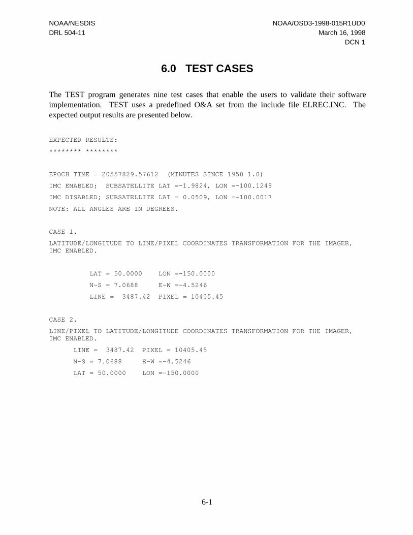
NOAA/NESDIS NOAA/OSD3-1998-015R1UD0
DRL 504-11 March 16, 1998
DCN 1
6-1
6.0 TEST CASES
The TEST program generates nine test cases that enable the users to validate their softwareimplementation. TEST uses a predefined O&A set from the include file ELREC.INC. Theexpected output results are presented below.
EXPECTED RESULTS:
******** ********
EPOCH TIME = 20557829.57612 (MINUTES SINCE 1950 1.0)
IMC ENABLED; SUBSATELLITE LAT =-1.9824, LON =-100.1249
IMC DISABLED; SUBSATELLITE LAT = 0.0509, LON =-100.0017
NOTE: ALL ANGLES ARE IN DEGREES.
CASE 1.
LATITUDE/LONGITUDE TO LINE/PIXEL COORDINATES TRANSFORMATION FOR THE IMAGER,IMC ENABLED.
LAT = 50.0000 LON =-150.0000
N-S = 7.0688 E-W =-4.5246
LINE = 3487.42 PIXEL = 10405.45
CASE 2.
LINE/PIXEL TO LATITUDE/LONGITUDE COORDINATES TRANSFORMATION FOR THE IMAGER,IMC ENABLED.
LINE = 3487.42 PIXEL = 10405.45
N-S = 7.0688 E-W =-4.5246
LAT = 50.0000 LON =-150.0000

NOAA/NESDIS NOAA/OSD3-1998-015R1UD0
DRL 504-11 March 16, 1998
DCN 1
6-2
CASE 3.
LATITUDE/LONGITUDE TO LINE/PIXEL COORDINATES TRANSFORMATION FOR THE SOUNDER,IMC ENABLED.
LAT =-50.0000 LON = -50.0000
N-S =-6.8659 E-W = 4.5781
LINE = 1219.38 PIXEL = 1162.93
CASE 4.
LINE/PIXEL TO LATITUDE/LONGITUDE COORDINATES TRANSFORMATION FOR THE SOUNDER,IMC ENABLED.
LINE = 1219.38 PIXEL = 1162.93
N-S =-6.8659 E-W = 4.5781
LAT =-50.0000 LON = -50.0000
CASE 5.
LATITUDE/LONGITUDE TO LINE/PIXEL COORDINATES TRANSFORMATION FOR THE IMAGER,IMC DISABLED.
LAT = 50.0000 LON =-150.0000
N-S = 6.8594 E-W =-4.6513
LINE = 3617.98 PIXEL = 10267.21
CASE 6.
LINE/PIXEL TO LATITUDE/LONGITUDE COORDINATES TRANSFORMATION FOR THE IMAGER,IMC DISABLED.
LINE = 3617.98 PIXEL = 10267.21
N-S = 6.8594 E-W =-4.6513
LAT = 49.9999 LON =-149.9997
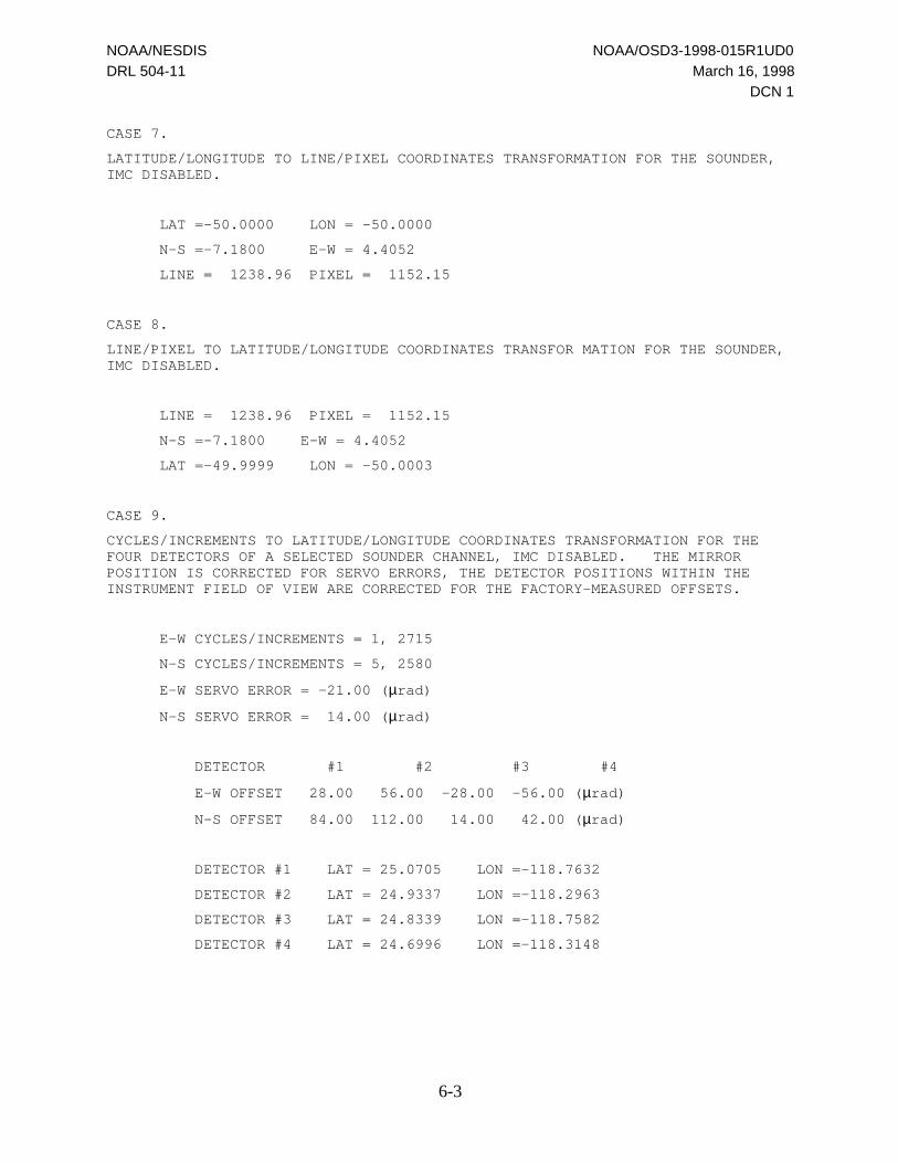
NOAA/NESDIS NOAA/OSD3-1998-015R1UD0
DRL 504-11 March 16, 1998
DCN 1
6-3
CASE 7.
LATITUDE/LONGITUDE TO LINE/PIXEL COORDINATES TRANSFORMATION FOR THE SOUNDER,IMC DISABLED.
LAT =-50.0000 LON = -50.0000
N-S =-7.1800 E-W = 4.4052
LINE = 1238.96 PIXEL = 1152.15
CASE 8.
LINE/PIXEL TO LATITUDE/LONGITUDE COORDINATES TRANSFOR MATION FOR THE SOUNDER,IMC DISABLED.
LINE = 1238.96 PIXEL = 1152.15
N-S =-7.1800 E-W = 4.4052
LAT =-49.9999 LON = -50.0003
CASE 9.
CYCLES/INCREMENTS TO LATITUDE/LONGITUDE COORDINATES TRANSFORMATION FOR THEFOUR DETECTORS OF A SELECTED SOUNDER CHANNEL, IMC DISABLED. THE MIRRORPOSITION IS CORRECTED FOR SERVO ERRORS, THE DETECTOR POSITIONS WITHIN THEINSTRUMENT FIELD OF VIEW ARE CORRECTED FOR THE FACTORY-MEASURED OFFSETS.
E-W CYCLES/INCREMENTS = 1, 2715
N-S CYCLES/INCREMENTS = 5, 2580
E-W SERVO ERROR = -21.00 (µrad)
N-S SERVO ERROR = 14.00 (µrad)
DETECTOR #1 #2 #3 #4
E-W OFFSET 28.00 56.00 -28.00 -56.00 (µrad)
N-S OFFSET 84.00 112.00 14.00 42.00 (µrad)
DETECTOR #1 LAT = 25.0705 LON =-118.7632
DETECTOR #2 LAT = 24.9337 LON =-118.2963
DETECTOR #3 LAT = 24.8339 LON =-118.7582
DETECTOR #4 LAT = 24.6996 LON =-118.3148

NOAA/NESDIS NOAA/OSD3-1998-015R1UD0
DRL 504-11 March 16, 1998
DCN 1
A-1
Appendix A.
Example of OGE Earth LocationSoftware Usage

NOAA/NESDIS NOAA/OSD3-1998-015R1UD0
DRL 504-11 March 16, 1998
DCN 1
A-2
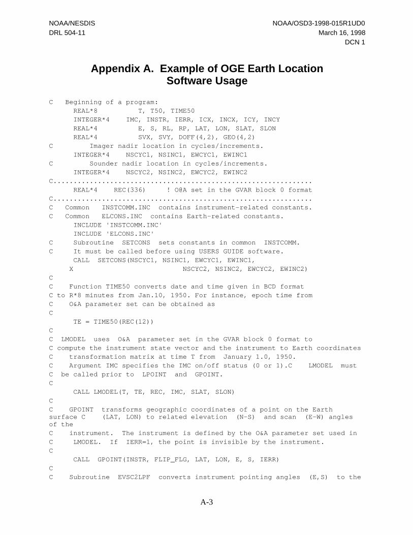
NOAA/NESDIS NOAA/OSD3-1998-015R1UD0
DRL 504-11 March 16, 1998
DCN 1
A-3
Appendix A. Example of OGE Earth LocationSoftware Usage
C Beginning of a program: REAL*8 T, T50, TIME50 INTEGER*4 IMC, INSTR, IERR, ICX, INCX, ICY, INCY REAL*4 E, S, RL, RP, LAT, LON, SLAT, SLON REAL*4 SVX, SVY, DOFF(4,2), GEO(4,2)C Imager nadir location in cycles/increments. INTEGER*4 NSCYC1, NSINC1, EWCYC1, EWINC1C Sounder nadir location in cycles/increments. INTEGER*4 NSCYC2, NSINC2, EWCYC2, EWINC2C................................................................ REAL*4 REC(336) ! O@A set in the GVAR block 0 formatC................................................................C Common INSTCOMM.INC contains instrument-related constants.C Common ELCONS.INC contains Earth-related constants. INCLUDE 'INSTCOMM.INC' INCLUDE 'ELCONS.INC'C Subroutine SETCONS sets constants in common INSTCOMM.C It must be called before using USERS GUIDE software. CALL SETCONS(NSCYC1, NSINC1, EWCYC1, EWINC1, X NSCYC2, NSINC2, EWCYC2, EWINC2)CC Function TIME50 converts date and time given in BCD formatC to R*8 minutes from Jan.10, 1950. For instance, epoch time fromC O&A parameter set can be obtained asC TE = TIME50(REC(12))CC LMODEL uses O&A parameter set in the GVAR block 0 format toC compute the instrument state vector and the instrument to Earth coordinatesC transformation matrix at time T from January 1.0, 1950.C Argument IMC specifies the IMC on/off status (0 or 1).C LMODEL mustC be called prior to LPOINT and GPOINT.C CALL LMODEL(T, TE, REC, IMC, SLAT, SLON)CC GPOINT transforms geographic coordinates of a point on the Earthsurface C (LAT, LON) to related elevation (N-S) and scan (E-W) anglesof theC instrument. The instrument is defined by the O&A parameter set used inC LMODEL. If IERR=1, the point is invisible by the instrument.C CALL GPOINT(INSTR, FLIP_FLG, LAT, LON, E, S, IERR)CC Subroutine EVSC2LPF converts instrument pointing angles (E,S) to the

NOAA/NESDIS NOAA/OSD3-1998-015R1UD0
DRL 504-11 March 16, 1998
DCN 1
A-4
C related line and pixel numbers (RL, RP)C IF (IERR. EQ. 0) CALL EVSC2LPF(INSTR, E, S, RL, RP)CC Functions EVLN and SCPX convert, respectively, line and pixelC numbers (RL, RP) to the instrument elevation (N-S) and scan (E-W)C angles.C E = EVLN(INSTR, RL) S = SCPX(INSTR, RP)CC LPOINT transforms elevation and scan angles to geographic coordinates.C Output flag IERR=1 if the instrument looks off the Earth.C The instrument is defined by the O&A parameter set used in LMODEL.C CALL LPOINT(INSTR, FLIP_FLG, E, S, LAT, LON, IERR)CC SNDELOC computes latitudes and longitudes related to four detectorsC of the Sounder instrument. The instrument pointing is given by the E-WC cycles/increments (ICX, INCX) and the N-S cycles/incrementsC (ICY, INCY).C CALL SNDELOC(FLIP_FLG, ICX, INCX, ICY, INCY, SVX, SVY, DOFF, GEO)

NOAA/NESDIS NOAA/OSD3-1998-015R1UD0
DRL 504-11 March 16, 1998
DCN 1
B-1
Appendix B.
OGE Earth Location Software Listings

NOAA/NESDIS NOAA/OSD3-1998-015R1UD0
DRL 504-11 March 16, 1998
DCN 1
B-2

NOAA/NESDIS NOAA/OSD3-1998-015R1UD0
DRL 504-11 March 16, 1998
DCN 1
B-3
B. OGE EARTH LOCATION SOFTWARE LISTINGS
C***********************************************************************C***********************************************************************C**C** INTEGRAL SYSTEMS, INC.C**C***********************************************************************C**C** PROJECT : OPERATIONS GROUND EQUIPMENT FOR GOES-NEXTC** SYSTEM : EARTH LOCATION USERS GUIDEC** PROGRAM : TESTC** SOURCE : TEST.FORC** LOAD NAME : ANYC** PROGRAMMER: IGOR LEVINEC**C** VER. DATA BY COMMENTC** ---- -------- --- ---------------------------------------------C** 1 10/03/89 IL INITIAL CREATIONC** 2 06/06/94 IL NOW SETCONS IS CALLED WITH 8 ARGUMENTSC**C***********************************************************************C**C** THIS PROGRAM GENERATES TEST CASES TO VALIDATE THE USER'SC** IMPLEMENTATIONS OF SOFTWARE FOR TRANSFORMATIONS BETWEENC** THE LATITUDE/LONGITUDE AND LINE/PIXEL COORDINAT SYSTEMS.C** THE RELATED O&A PARAMETER SET IS DEFINED IN INCLUDE FILE I.ELREC.C**C***********************************************************************C**C** CALLED BY : NONEC** COMMONS MODIFIED: NONEC** INPUTS : NONEC** OUTPUTS : NONEC** ROUTINES CALLED : SETCONS,LMODEL,EVLN,SCPX,LPOINT,C** GPOINT,EVSC2LPF,SNDELOCC**C***********************************************************************C*********************************************************************** PROGRAM TEST IMPLICIT NONECC CALLING PARAMETERSCCC LOCAL VARIABLESC REAL*8 T,TIME50,TU,DLAT(2),DLON(2) REAL DOFF(4,2),GEO(4,2),RLAT,RLON,E,S,RL,RP,EVLN,SCPX,SVX,SVY INTEGER INSTR,IMC,IER,ICX,INCX,ICY,INCY,I,J,FLIP_FLGCC INCLUDE FILESC INCLUDE 'ELCONS.INC' INCLUDE 'INSTCOMM.INC' INCLUDE 'ELCOMM.INC' INCLUDE 'ELREC.INC'
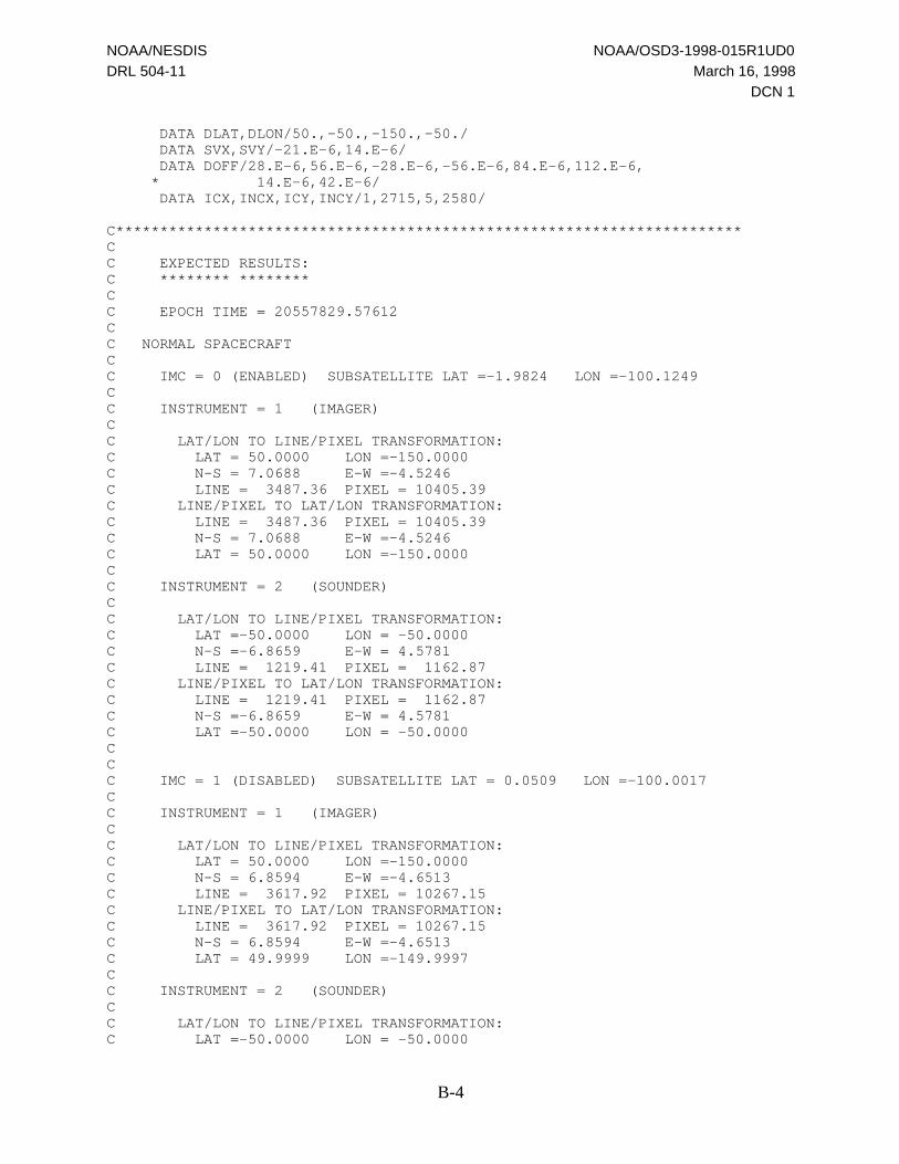
NOAA/NESDIS NOAA/OSD3-1998-015R1UD0
DRL 504-11 March 16, 1998
DCN 1
B-4
DATA DLAT,DLON/50.,-50.,-150.,-50./ DATA SVX,SVY/-21.E-6,14.E-6/ DATA DOFF/28.E-6,56.E-6,-28.E-6,-56.E-6,84.E-6,112.E-6, * 14.E-6,42.E-6/ DATA ICX,INCX,ICY,INCY/1,2715,5,2580/
C***********************************************************************CC EXPECTED RESULTS:C ******** ********CC EPOCH TIME = 20557829.57612CC NORMAL SPACECRAFTCC IMC = 0 (ENABLED) SUBSATELLITE LAT =-1.9824 LON =-100.1249CC INSTRUMENT = 1 (IMAGER)CC LAT/LON TO LINE/PIXEL TRANSFORMATION:C LAT = 50.0000 LON =-150.0000C N-S = 7.0688 E-W =-4.5246C LINE = 3487.36 PIXEL = 10405.39C LINE/PIXEL TO LAT/LON TRANSFORMATION:C LINE = 3487.36 PIXEL = 10405.39C N-S = 7.0688 E-W =-4.5246C LAT = 50.0000 LON =-150.0000CC INSTRUMENT = 2 (SOUNDER)CC LAT/LON TO LINE/PIXEL TRANSFORMATION:C LAT =-50.0000 LON = -50.0000C N-S =-6.8659 E-W = 4.5781C LINE = 1219.41 PIXEL = 1162.87C LINE/PIXEL TO LAT/LON TRANSFORMATION:C LINE = 1219.41 PIXEL = 1162.87C N-S =-6.8659 E-W = 4.5781C LAT =-50.0000 LON = -50.0000CCC IMC = 1 (DISABLED) SUBSATELLITE LAT = 0.0509 LON =-100.0017CC INSTRUMENT = 1 (IMAGER)CC LAT/LON TO LINE/PIXEL TRANSFORMATION:C LAT = 50.0000 LON =-150.0000C N-S = 6.8594 E-W =-4.6513C LINE = 3617.92 PIXEL = 10267.15C LINE/PIXEL TO LAT/LON TRANSFORMATION:C LINE = 3617.92 PIXEL = 10267.15C N-S = 6.8594 E-W =-4.6513C LAT = 49.9999 LON =-149.9997CC INSTRUMENT = 2 (SOUNDER)CC LAT/LON TO LINE/PIXEL TRANSFORMATION:C LAT =-50.0000 LON = -50.0000

NOAA/NESDIS NOAA/OSD3-1998-015R1UD0
DRL 504-11 March 16, 1998
DCN 1
B-5
C N-S =-7.1650 E-W = 4.3902C LINE = 1238.05 PIXEL = 1151.16C LINE/PIXEL TO LAT/LON TRANSFORMATION:C LINE = 1238.05 PIXEL = 1151.16C N-S =-7.1650 E-W = 4.3902C LAT =-49.9999 LON = -50.0003CC CYCLES/INCREMENTS TO LAT/LON TRANSFORMATION:C E-W CYCLES/INCREMENTS = 1, 2715C N-S CYCLES/INCREMENTS = 5, 2580C E-W SERVO ERROR = -21.00 (mrad)C N-S SERVO ERROR = 14.00 (mrad)CC DETECTOR #1 #2 #3 #4C E-W OFFSET 28.00 56.00 -28.00 -56.00 (mrad)C N-S OFFSET 84.00 112.00 14.00 42.00 (mrad)CC DETECTOR #1 LAT = 25.1035 LON =-118.8478C DETECTOR #2 LAT = 25.0270 LON =-118.3774C DETECTOR #3 LAT = 24.8625 LON =-118.8069C DETECTOR #4 LAT = 24.7853 LON =-118.3595CC FLIPPED (INVERTED SPACECRAFTCC IMC = 0 (ENABLED) SUBSATELLITE LAT =-1.9824 LON =-100.1249CC INSTRUMENT = 1 (IMAGER)CC LAT/LON TO LINE/PIXEL TRANSFORMATION:C LAT = 50.0000 LON =-150.0000C N-S = 7.0688 E-W =-4.5246C LINE = 3487.36 PIXEL = 10405.39C LINE/PIXEL TO LAT/LON TRANSFORMATION:C LINE = 3487.36 PIXEL = 10405.39C N-S = 7.0688 E-W =-4.5246C LAT = 50.0000 LON =-150.0000CC INSTRUMENT = 2 (SOUNDER)CC LAT/LON TO LINE/PIXEL TRANSFORMATION:C LAT =-50.0000 LON = -50.0000C N-S =-6.8659 E-W = 4.5780C LINE = 1219.35 PIXEL = 1162.99C LINE/PIXEL TO LAT/LON TRANSFORMATION:C LINE = 1219.35 PIXEL = 1162.99C N-S =-6.8659 E-W = 4.5780C LAT =-50.0000 LON = -50.0000CCC IMC = 1 (DISABLED) SUBSATELLITE LAT = 0.0509 LON =-100.0017CC INSTRUMENT = 1 (IMAGER)CC LAT/LON TO LINE/PIXEL TRANSFORMATION:C LAT = 50.0000 LON =-150.0000C N-S = 6.8450 E-W =-4.6370C LINE = 3626.88 PIXEL = 10282.76

NOAA/NESDIS NOAA/OSD3-1998-015R1UD0
DRL 504-11 March 16, 1998
DCN 1
B-6
C LINE/PIXEL TO LAT/LON TRANSFORMATION:C LINE = 3626.88 PIXEL = 10282.76C N-S = 6.8450 E-W =-4.6370C LAT = 49.9998 LON =-149.9996CC INSTRUMENT = 2 (SOUNDER)CC LAT/LON TO LINE/PIXEL TRANSFORMATION:C LAT =-50.0000 LON = -50.0000C N-S =-7.1800 E-W = 4.4052C LINE = 1238.93 PIXEL = 1152.22C LINE/PIXEL TO LAT/LON TRANSFORMATION:C LINE = 1238.93 PIXEL = 1152.22C N-S =-7.1800 E-W = 4.4052C LAT =-49.9998 LON = -50.0003CC CYCLES/INCREMENTS TO LAT/LON TRANSFORMATION:C E-W CYCLES/INCREMENTS = 1, 2715C N-S CYCLES/INCREMENTS = 5, 2580C E-W SERVO ERROR = -21.00 (mrad)C N-S SERVO ERROR = 14.00 (mrad)CC DETECTOR #1 #2 #3 #4C E-W OFFSET 28.00 56.00 -28.00 -56.00 (mrad)C N-S OFFSET 84.00 112.00 14.00 42.00 (mrad)CC DETECTOR #1 LAT =-22.5543 LON = -80.4361C DETECTOR #2 LAT =-22.6288 LON = -79.9716C DETECTOR #3 LAT =-22.7889 LON = -80.3995C DETECTOR #4 LAT =-22.8645 LON = -79.9554CC NOTE: LAT, LON, AND N-S, E-W ANGLES ARE IN DEGREES.CC***********************************************************************
C SET CONSTANTS IN COMMON INSTCOMM CALL SETCONS(4,3068,2,3068,4,1402,2,1402)
C COMPUTE EPOCH TIMEC TU=TIME50(REC(12)) TU=20557829.57612 PRINT 500,TU T=TU+20. DO FLIP_FLG = 1, -1, -2 DO IMC=0,1
C COMPUTE DATA NEEDED FOR INSTRUMENT TO EARTH COORDINATESC TRANSFORMATION CALL LMODEL(T,TU,REC,IMC,RLAT,RLON) PRINT 510,IMC,RLAT*DEG,RLON*DEG
DO INSTR=1,2
C GEOGRAPHIC TO LINE/PIXEL COORDINATES TRANSFORMATION:C SET INPUT LATITUDE AND LONGITUDE RLAT=DLAT(INSTR)*RAD RLON=DLON(INSTR)*RAD

NOAA/NESDIS NOAA/OSD3-1998-015R1UD0
DRL 504-11 March 16, 1998
DCN 1
B-7
PRINT 520,INSTR,DLAT(INSTR),DLON(INSTR)
C TRANSFORM LAT/LON TO N-S AND E-W INSTRUMENT ANGLES CALL GPOINT(INSTR,FLIP_FLG,RLAT,RLON,E,S,IER) IF (IER.EQ.0) THEN
C CONVERT N-S AND E-W ANGLES TO LINE/PIXEL COORDINATES CALL EVSC2LPF(INSTR,E,S,RL,RP) PRINT 530,E*DEG,S*DEG,RL,RP
C REVERSE TRANSFORMATION: LINE/PIXEL TO GEOGRAPHIC COORDINATES
C CONVERT LINE/PIXEL NUMBERS TO N-S AND E-W INSTRUMENT ANGLES E=EVLN(INSTR,RL) S=SCPX(INSTR,RP) PRINT 540,RL,RP,E*DEG,S*DEG
C TRANSFORM N-S AND E-W ANGLES TO GEOGRAPHIC COORDINATES CALL LPOINT(INSTR,FLIP_FLG,E,S,RLAT,RLON,IER) IF (IER.EQ.0) PRINT 550,RLAT*DEG,RLON*DEG END IF ENDDO ENDDO
C TRANSFORM CYCLES/INCREMENTS, SERVO ERROR VALUES AND THEC FACTORY-MEASURED DETECTOR OFFSETS TO LAT/LON COORDINATESC FOR THE FOUR DETECTORS OF THE SOUNDER INSTRUMENT
CALL SNDELOC(FLIP_FLG,ICX,INCX,ICY,INCY,SVX,SVY,DOFF,GEO)
PRINT 560,ICX,INCX,ICY,INCY,SVX*1.E6,SVY*1.E6 PRINT 570,((DOFF(I,J)*1.E6,I=1,4),J=1,2) PRINT 580, (I,GEO(I,1)*DEG,GEO(I,2)*DEG,I=1,4) CALL SETCONS(4,3068,2,3068,4,1403,2,1403) ENDDO
500 FORMAT(1X,'EPOCH TIME =',F15.5) 510 FORMAT(//1X,'IMC =',I2,3X,'SUBSATELLITE LAT =', * F7.4,3X,'LON =',F9.4) 520 FORMAT(/1X,'INSTRUMENT =',I2/ * /3X,'LAT/LON TO LINE/PIXEL TRANSFORMATION:'/ * 5X,'LAT =',F8.4,4X,'LON =',F9.4) 530 FORMAT(5X,'N-S =',F7.4,5X,'E-W =',F7.4/ * 5X,'LINE =',F9.2,2X,'PIXEL =',F9.2) 540 FORMAT(3X,'LINE/PIXEL TO LAT/LON TRANSFORMATION:'/ * 5X,'LINE =',F9.2,2X,'PIXEL =',F9.2/ * 5X,'N-S =',F7.4,5X,'E-W =',F7.4) 550 FORMAT(5X,'LAT =',F8.4,4X,'LON =',F9.4) 560 FORMAT(/3X,'CYCLES/INCREMENTS TO LAT/LON TRANSFORMATION:'/ * 5X,'E-W CYCLES/INCREMENTS =',I2,',',I5/ * 5X,'N-S CYCLES/INCREMENTS =',I2,',',I5/ * 5X,'E-W SERVO ERROR =',F7.2,' (mrad)'/ * 5X,'N-S SERVO ERROR =',F7.2,' (mrad)') 570 FORMAT(/5X,'DETECTOR',6X,'#1',6X,'#2',6X,'#3',6X,'#4'/ * 5X,'E-W OFFSET',4F8.2,' (mrad)'/ * 5X,'N-S OFFSET',4F8.2,' (mrad)'/) 580 FORMAT(5X,'DETECTOR #',I1,3X,'LAT =',F8.4,2X,'LON =',F9.4)

NOAA/NESDIS NOAA/OSD3-1998-015R1UD0
DRL 504-11 March 16, 1998
DCN 1
B-8
END
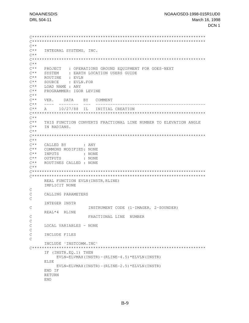
NOAA/NESDIS NOAA/OSD3-1998-015R1UD0
DRL 504-11 March 16, 1998
DCN 1
B-9
C***********************************************************************C***********************************************************************C**C** INTEGRAL SYSTEMS, INC.C**C***********************************************************************C**C** PROJECT : OPERATIONS GROUND EQUIPMENT FOR GOES-NEXTC** SYSTEM : EARTH LOCATION USERS GUIDEC** ROUTINE : EVLNC** SOURCE : EVLN.FORC** LOAD NAME : ANYC** PROGRAMMER: IGOR LEVINEC**C** VER. DATA BY COMMENTC** ---- -------- --- ---------------------------------------------C** A 10/27/88 IL INITIAL CREATIONC***********************************************************************C**C** THIS FUNCTION CONVERTS FRACTIONAL LINE NUMBER TO ELEVATION ANGLEC** IN RADIANS.C**C***********************************************************************C**C** CALLED BY : ANYC** COMMONS MODIFIED: NONEC** INPUTS : NONEC** OUTPUTS : NONEC** ROUTINES CALLED : NONEC**C***********************************************************************C*********************************************************************** REAL FUNCTION EVLN(INSTR,RLINE) IMPLICIT NONECC CALLING PARAMETERSC INTEGER INSTRC INSTRUMENT CODE (1-IMAGER, 2-SOUNDER) REAL*4 RLINEC FRACTIONAL LINE NUMBERCC LOCAL VARIABLES - NONECC INCLUDE FILESC INCLUDE 'INSTCOMM.INC'C*********************************************************************** IF (INSTR.EQ.1) THEN EVLN=ELVMAX(INSTR)-(RLINE-4.5)*ELVLN(INSTR) ELSE EVLN=ELVMAX(INSTR)-(RLINE-2.5)*ELVLN(INSTR) END IF RETURN END
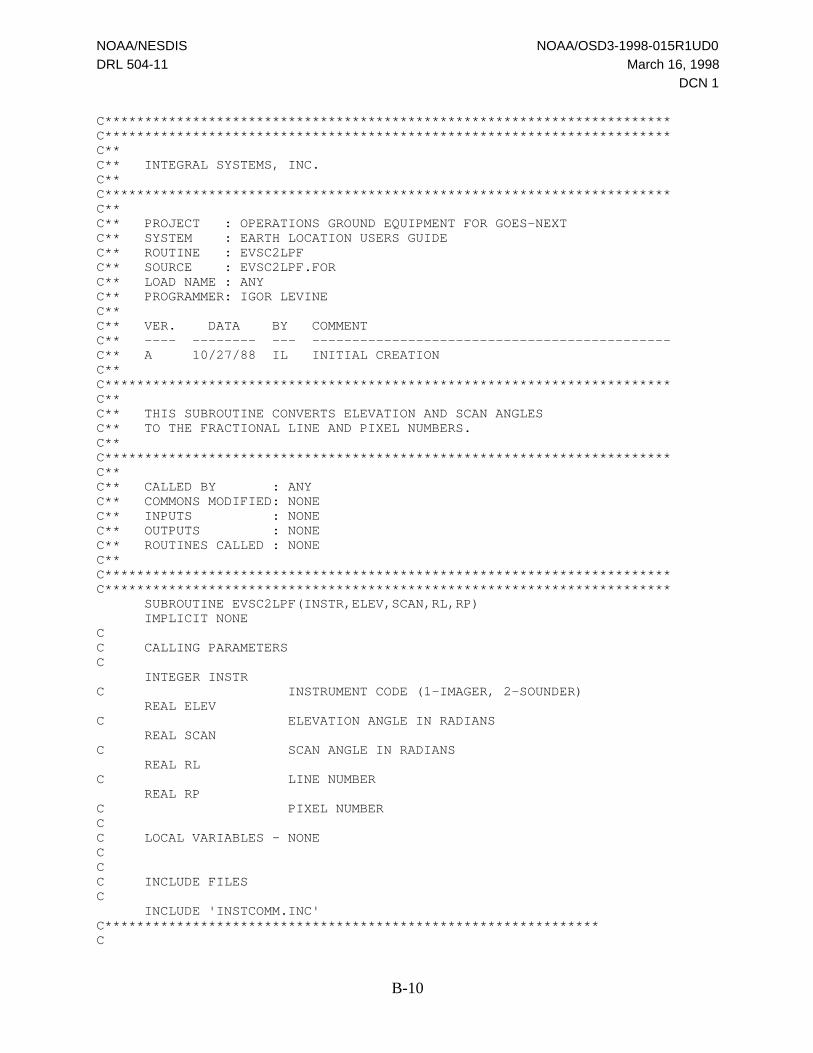
NOAA/NESDIS NOAA/OSD3-1998-015R1UD0
DRL 504-11 March 16, 1998
DCN 1
B-10
C***********************************************************************C***********************************************************************C**C** INTEGRAL SYSTEMS, INC.C**C***********************************************************************C**C** PROJECT : OPERATIONS GROUND EQUIPMENT FOR GOES-NEXTC** SYSTEM : EARTH LOCATION USERS GUIDEC** ROUTINE : EVSC2LPFC** SOURCE : EVSC2LPF.FORC** LOAD NAME : ANYC** PROGRAMMER: IGOR LEVINEC**C** VER. DATA BY COMMENTC** ---- -------- --- ---------------------------------------------C** A 10/27/88 IL INITIAL CREATIONC**C***********************************************************************C**C** THIS SUBROUTINE CONVERTS ELEVATION AND SCAN ANGLESC** TO THE FRACTIONAL LINE AND PIXEL NUMBERS.C**C***********************************************************************C**C** CALLED BY : ANYC** COMMONS MODIFIED: NONEC** INPUTS : NONEC** OUTPUTS : NONEC** ROUTINES CALLED : NONEC**C***********************************************************************C*********************************************************************** SUBROUTINE EVSC2LPF(INSTR,ELEV,SCAN,RL,RP) IMPLICIT NONECC CALLING PARAMETERSC INTEGER INSTRC INSTRUMENT CODE (1-IMAGER, 2-SOUNDER) REAL ELEVC ELEVATION ANGLE IN RADIANS REAL SCANC SCAN ANGLE IN RADIANS REAL RLC LINE NUMBER REAL RPC PIXEL NUMBERCC LOCAL VARIABLES - NONECCC INCLUDE FILESC INCLUDE 'INSTCOMM.INC'C**************************************************************C
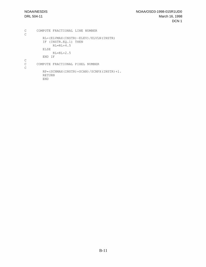
NOAA/NESDIS NOAA/OSD3-1998-015R1UD0
DRL 504-11 March 16, 1998
DCN 1
B-11
C COMPUTE FRACTIONAL LINE NUMBERC RL=(ELVMAX(INSTR)-ELEV)/ELVLN(INSTR) IF (INSTR.EQ.1) THEN RL=RL+4.5 ELSE RL=RL+2.5 END IFCC COMPUTE FRACTIONAL PIXEL NUMBERC RP=(SCNMAX(INSTR)+SCAN)/SCNPX(INSTR)+1. RETURN END
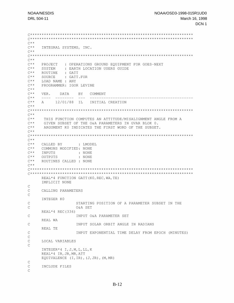
NOAA/NESDIS NOAA/OSD3-1998-015R1UD0
DRL 504-11 March 16, 1998
DCN 1
B-12
C***********************************************************************C***********************************************************************C**C** INTEGRAL SYSTEMS, INC.C**C***********************************************************************C**C** PROJECT : OPERATIONS GROUND EQUIPMENT FOR GOES-NEXTC** SYSTEM : EARTH LOCATION USERS GUIDEC** ROUTINE : GATTC** SOURCE : GATT.FORC** LOAD NAME : ANYC** PROGRAMMER: IGOR LEVINEC**C** VER. DATA BY COMMENTC** ---- -------- --- ---------------------------------------------C** A 12/01/88 IL INITIAL CREATIONC**C***********************************************************************C**C** THIS FUNCTION COMPUTES AN ATTITUDE/MISALIGNMENT ANGLE FROM AC** GIVEN SUBSET OF THE O&A PARAMETERS IN GVAR BLOK 0.C** ARGUMENT K0 INDICATES THE FIRST WORD OF THE SUBSET.C**C***********************************************************************C**C** CALLED BY : LMODELC** COMMONS MODIFIED: NONEC** INPUTS : NONEC** OUTPUTS : NONEC** ROUTINES CALLED : NONEC**C***********************************************************************C*********************************************************************** REAL*4 FUNCTION GATT(K0,REC,WA,TE) IMPLICIT NONECC CALLING PARAMETERSC INTEGER K0C STARTING POSITION OF A PARAMETER SUBSET IN THEC O&A SET REAL*4 REC(336)C INPUT O&A PARAMETER SET REAL WAC INPUT SOLAR ORBIT ANGLE IN RADIANS REAL TEC INPUT EXPONENTIAL TIME DELAY FROM EPOCH (MINUTES)CC LOCAL VARIABLESC INTEGER*4 I,J,M,L,LL,K REAL*4 IR,JR,MR,ATT EQUIVALENCE (I,IR),(J,JR),(M,MR)CC INCLUDE FILESC

NOAA/NESDIS NOAA/OSD3-1998-015R1UD0
DRL 504-11 March 16, 1998
DCN 1
B-13
C***********************************************************************CC CONSTANT COMPONENTC K=K0 ATT=REC(K+2)CC COMPUTES THE EXPONENTIAL TERMC IF (TE.GE.0.AND.REC(K+1).GT.0.) ATT=ATT+REC(K)*EXP(-TE/REC(K+1))CC EXTRACTS THE NUMBER OF SINUSOIDSC IR=REC(K+3)CC CALCULATION OF SINUSOIDSC DO 10 L=1,I ATT=ATT+REC(K+2*L+2)*COS(WA*L+REC(K+2*L+3)) 10 CONTINUECC POINTER TO THE NUMBER OF MONOMIAL SINUSOIDSC K=K+34CC EXTACTS NUMBER OF MONOMIAL SINUSOIDSC IR=REC(K)CC COMPUTES MONOMIAL SINUSOIDSC DO 20 L=1,I LL=K+5*LCC ORDER OF SINUSOIDC JR=REC(LL-4)CC ORDER OF MONOMIAL SINUSOIDC MR=REC(LL-3) ATT=ATT+REC(LL-2)*((WA-REC(LL))**M)*COS(J*WA+REC(LL-1)) 20 CONTINUE GATT=ATT RETURN END

NOAA/NESDIS NOAA/OSD3-1998-015R1UD0
DRL 504-11 March 16, 1998
DCN 1
B-14
C***********************************************************************C***********************************************************************C**C** INTEGRAL SYSTEMS, INC.C**C***********************************************************************C**C** PROJECT : OPERATIONS GROUND EQUIPMENT FOR GOES-NEXTC** SYSTEM : EARTH LOCATION USERS GUIDEC** ROUTINE : GPOINTC** SOURCE : GPOINT.FORC** LOAD NAME : ANYC** PROGRAMMER: IGOR LEVINEC**C** VER. DATA BY COMMENTC** ---- -------- --- ---------------------------------------------C** 1 12/10/87 IL INITIAL CREATIONC** 2 06/10/88 IL REPLACED ASIN WITH ATAN TO SAVE TIMEC** 3 06/02/89 IL COORDINATE AXES CHANGED ACCORDING TOC** FORD'S DEFINITION IN SDAIP, DRL 504-01C** 4 12/01/93 IL IMPLEMENTED NEW FORMULAE FOR SCAN ANGLEC** CORRECTIONS DUE TO MISALIGNMENTS.C**C***********************************************************************C**C** THIS SUBROUTINE CONVERTS GEOGRAPHIC LATITUDE AND LONGITUDEC** TO THE RELATED ELEVATION AND SCAN ANGLES.C**C***********************************************************************C**C** CALLED BY : ANYC** COMMONS MODIFIED: NONEC** INPUTS : NONEC** OUTPUTS : NONEC** ROUTINES CALLED : NONEC**C***********************************************************************C*********************************************************************** SUBROUTINE GPOINT(INSTR,FLIP_FLG,RLAT,RLON,ALF,GAM,IERR) IMPLICIT NONECC CALLING PARAMETERSC INTEGER*4 INSTRC INSTRUMENT CODE (1=IMAGER,2=SOUNDER) INTEGER*4 FLIP_FLGC S/C ORIENTATION FLAG (1=NORMAL,-1=INVERTED) REAL*4 RLATc GEOGRAPHIC LATITUDE IN RADIANS (INPUT) REAL*4 RLONc GEOGRAPHIC LONGITUDE IN RADIANS (INPUT) REAL*4 ALFc ELEVATION ANGLE IN RADIANS (OUTPUT) REAL*4 GAMc SCAN ANGLE IN RADIANS (OUTPUT) INTEGER IERRc OUTPUT STATUS; 0 - SUCCESSFUL COMPLETION,
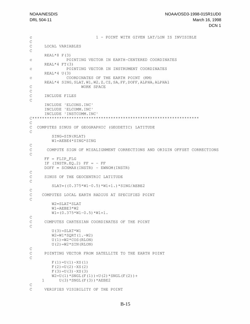
NOAA/NESDIS NOAA/OSD3-1998-015R1UD0
DRL 504-11 March 16, 1998
DCN 1
B-15
c 1 - POINT WITH GIVEN LAT/LON IS INVISIBLECC LOCAL VARIABLESC REAL*8 F(3)c POINTING VECTOR IN EARTH-CENTERED COORDINATES REAL*4 FT(3)c POINTING VECTOR IN INSTRUMENT COORDINATES REAL*4 U(3)c COORDINATES OF THE EARTH POINT (KM) REAL*4 SING,SLAT,W1,W2,Z,CZ,SA,FF,DOFF,ALPHA,ALPHA1C WORK SPACECC INCLUDE FILESC INCLUDE 'ELCONS.INC' INCLUDE 'ELCOMM.INC' INCLUDE 'INSTCOMM.INC'C********************************************************************CC COMPUTES SINUS OF GEOGRAPHIC (GEODETIC) LATITUDEC SING=SIN(RLAT) W1=AEBE4*SING*SINGCC COMPUTE SIGN OF MISALIGNMENT CORRECTIONS AND ORIGIN OFFSET CORRECTIONSC FF = FLIP_FLG IF (INSTR.EQ.2) FF = - FF DOFF = SCNMAX(INSTR) - EWNOM(INSTR)CC SINUS OF THE GEOCENTRIC LATITUDEC SLAT=((0.375*W1-0.5)*W1+1.)*SING/AEBE2CC COMPUTES LOCAL EARTH RADIUS AT SPECIFIED POINTC W2=SLAT*SLAT W1=AEBE3*W2 W1=(0.375*W1-0.5)*W1+1.CC COMPUTES CARTESIAN COORDINATES OF THE POINTC U(3)=SLAT*W1 W2=W1*SQRT(1.-W2) U(1)=W2*COS(RLON) U(2)=W2*SIN(RLON)CC POINTING VECTOR FROM SATELLITE TO THE EARTH POINTC F(1)=U(1)-XS(1) F(2)=U(2)-XS(2) F(3)=U(3)-XS(3) W2=U(1)*SNGL(F(1))+U(2)*SNGL(F(2))+ 1 U(3)*SNGL(F(3))*AEBE2CC VERIFIES VISIBILITY OF THE POINT

NOAA/NESDIS NOAA/OSD3-1998-015R1UD0
DRL 504-11 March 16, 1998
DCN 1
B-16
C IF (W2.GT.0.) THEN IERR=1 ALF=99999. GAM=99999. RETURN END IFCC CONVERTS POINTING VECTOR TO INSTRUMENT COORDINATESC FT(1)=BT(1,1)*F(1)+BT(2,1)*F(2)+BT(3,1)*F(3) FT(2)=BT(1,2)*F(1)+BT(2,2)*F(2)+BT(3,2)*F(3) FT(3)=BT(1,3)*F(1)+BT(2,3)*F(2)+BT(3,3)*F(3)CC CONVERTS POINTING VECTOR TO SCAN AND ELEVATION ANGLES ANDC CORRECTS FOR THE ROLL AND PITCH MISALIGNMENTSC GAM=ATAN(FT(1)/SQRT(FT(2)**2+FT(3)**2)) ALF=-ATAN(FT(2)/FT(3)) W1=SIN(ALF) W2=COS(GAM) ALPHA1=ALF+RMA*(1.-COS(ALF)/W2)+PMA*W1*(FF/W2+TAN(GAM)) GAM=GAM-FF*RMA*W1 ALF = ALPHA1 + ALPHA1*GAM*DOFF GAM = GAM - 0.5*ALPHA1*ALPHA1*DOFF IERR=0 RETURN END
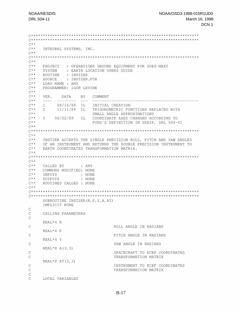
NOAA/NESDIS NOAA/OSD3-1998-015R1UD0
DRL 504-11 March 16, 1998
DCN 1
B-17
C***********************************************************************C***********************************************************************C**C** INTEGRAL SYSTEMS, INC.C**C***********************************************************************C**C** PROJECT : OPERATIONS GROUND EQUIPMENT FOR GOES-NEXTC** SYSTEM : EARTH LOCATION USERS GUIDEC** ROUTINE : INST2ERC** SOURCE : INST2ER.FORC** LOAD NAME : ANYC** PROGRAMMER: IGOR LEVINEC**C** VER. DATA BY COMMENTC** ---- -------- --- ---------------------------------------------C** 1 08/16/88 IL INITIAL CREATIONC** 2 11/11/88 IL TRIGONOMETRIC FUNCTIONS REPLACED WITHC** SMALL ANGLE APPROXIMATIONSC** 3 06/02/89 IL COORDINATE AXES CHANGED ACCORDING TOC** FORD'S DEFINITION IN SDAIP, DRL 504-01C**C***********************************************************************C**C** INST2ER ACCEPTS THE SINGLE PRECISION ROLL, PITCH AND YAW ANGLESC** OF AN INSTRUMENT AND RETURNS THE DOUBLE PRECISION INSTRUMENT TOC** EARTH COORDINATES TRANSFORMATION MATRIX.C**C***********************************************************************C**C** CALLED BY : ANYC** COMMONS MODIFIED: NONEC** INPUTS : NONEC** OUTPUTS : NONEC** ROUTINES CALLED : NONEC**C***********************************************************************C*********************************************************************** SUBROUTINE INST2ER(R,P,Y,A,AT) IMPLICIT NONECC CALLING PARAMETERSC REAL*4 RC ROLL ANGLE IN RADIANS REAL*4 PC PITCH ANGLE IN RADIANS REAL*4 YC YAW ANGLE IN RADIANS REAL*8 A(3,3)C SPACECRAFT TO ECEF COORDINATESC TRANSFORMATION MATRIX REAL*8 AT(3,3)C INSTRUMENT TO ECEF COORDINATESC TRANSFORMATION MATRIXCC LOCAL VARIABLES

NOAA/NESDIS NOAA/OSD3-1998-015R1UD0
DRL 504-11 March 16, 1998
DCN 1
B-18
C REAL*8 RPY(3,3)C INSTRUMENT TO BODY COORDINATESC TRANSFORMATION MATRIX REAL SR,CR,SP,CP,SY,CY INTEGER*4 I,JC INDICESCC INCLUDE FILESCC**********************************************************************CC COMPUTE INSTRUMENT TO BODY COORDINATES TRANSFORMATION MATRIXC SP=SIN(P) CP=COS(P) SR=SIN(R) CR=COS(R) SY=SIN(Y) CY=COS(Y) RPY(1,1)=CY*CP RPY(2,1)=CY*SP*SR+SY*CR RPY(3,1)=SY*SR-CY*SP*CR RPY(1,2)=-SY*CP RPY(2,2)=CY*CR-SP*SR*SY RPY(3,2)=CY*SR+SY*SP*CR RPY(1,3)=SP RPY(2,3)=-CP*SR RPY(3,3)=CP*CRCC MULTIPLICATION OF MATRICES A AND RPYC DO 10 I=1,3 DO 10 J=1,3 10 AT(I,J)=A(I,1)*RPY(1,J)+A(I,2)*RPY(2,J)+A(I,3)*RPY(3,J) RETURN END

NOAA/NESDIS NOAA/OSD3-1998-015R1UD0
DRL 504-11 March 16, 1998
DCN 1
B-19
C***********************************************************************C***********************************************************************C**C** INTEGRAL SYSTEMS, INC.C**C***********************************************************************C**C** PROJECT : OPERATIONS GROUND EQUIPMENT FOR GOES-NEXTC** SYSTEM : EARTH LOCATION USERS GUIDEC** ROUTINE : LMODELC** SOURCE : LMODEL.FORC** LOAD NAME : ANYC** PROGRAMMER: IGOR LEVINEC**C** VER. DATA BY COMMENTC** ---- -------- --- ---------------------------------------------C** 1 01/09/89 IL INITIAL CREATIONC** 2 06/02/89 IL COORDINATE AXES CHANGED ACCORDING TOC** FORD'S DEFINITION IN SDAIP, DRL 504-01C** 3 08/21/89 IL CORRECTED ORBIT ANGLE COMPUTATIONSC** 4 02/27/90 IL S/C COMPENSATION APPLIED UNCONDITIONALLY;C** REFERENCE RADIAL DISTANCE, LATITUDE ANDC** ORBIT YAW SET TO ZERO IF IMC DISABLED.C** 5 12/01/93 IL ADDED TRAP FOR SLAT=SYAW=0; CORRECTEDC** EXPRESSION FOR LAM.C**C***********************************************************************C**C** THIS SUBROUTINE COMPUTES THE POSITION OF THE SATELLITE AND THEC** ATTITUDE OF THE IMAGER OR SOUNDER. THE CALCULATIONS ARE BASEDC** ON THE OATS ORBIT AND ATTITUDE MODEL REPRESENTED BY THE O&AC** PARAMETER SET IN GVAR BLOCK 0.C** INPUTS:C** TIME, EPOCH TIME, O&A PARAMETER SET, IMC STATUS.C**C** OUTPUTS:C** THE SPACECRAFT POSITION VECTOR IN EARTH-FIXED COORDINATES;C** THE GEOMETRIC ROLL, PITCH, YAW ANGLES AND THE ROLL,C** PITCH MISALIGNMENTS FOR EITHER THE IMAGER OR THE SOUNDER;C** THE EARTH-FIXED TO INSTRUMENT FRAME TRANSFORMATION MATRIX;C** GEOGRAPHIC LATITUDE AND LONGITUDE AT SUBSATELLITE POINT.C**C** DESCRIPTIONC** LMODEL ACCEPTS AN INPUT DOUBLE PRECISION TIME IN MINUTES FROMC** 1950, JAN.1.0 AND AN INPUT SET OF O&A PARAMETERS AND COMPUTESC** POSITION OF THE SATELLITE, THE ATTITUDE ANGLES AND ATTITUDEC** MISALIGNMENTS AND THE INSTRUMENT TO EARTH-FIXED COORDINATESC** TRANSFORMATION MATRIX.C**C***********************************************************************C**C** CALLED BY : ANYC** COMMONS MODIFIED: /ELCOMM/ XS,Q3,PITCH,ROLL,YAW,PMA,RMA,BTC** INPUTS : NONEC** OUTPUTS : NONEC** ROUTINES CALLED : INST2ER,GATTC**
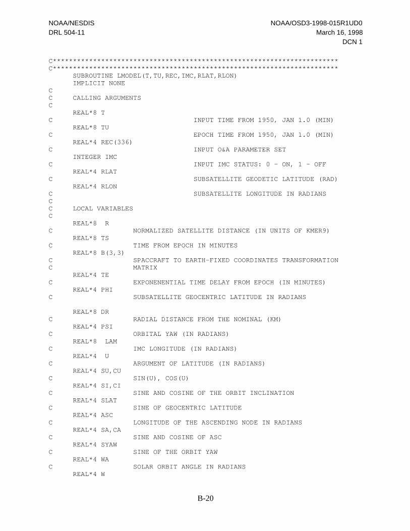
NOAA/NESDIS NOAA/OSD3-1998-015R1UD0
DRL 504-11 March 16, 1998
DCN 1
B-20
C***********************************************************************C*********************************************************************** SUBROUTINE LMODEL(T,TU,REC,IMC,RLAT,RLON) IMPLICIT NONECC CALLING ARGUMENTSC REAL*8 TC INPUT TIME FROM 1950, JAN 1.0 (MIN) REAL*8 TUC EPOCH TIME FROM 1950, JAN 1.0 (MIN) REAL*4 REC(336)C INPUT O&A PARAMETER SET INTEGER IMCC INPUT IMC STATUS: 0 - ON, 1 - OFF REAL*4 RLATC SUBSATELLITE GEODETIC LATITUDE (RAD) REAL*4 RLONC SUBSATELLITE LONGITUDE IN RADIANSCC LOCAL VARIABLESC REAL*8 RC NORMALIZED SATELLITE DISTANCE (IN UNITS OF KMER9) REAL*8 TSC TIME FROM EPOCH IN MINUTES REAL*8 B(3,3)C SPACCRAFT TO EARTH-FIXED COORDINATES TRANSFORMATIONC MATRIX REAL*4 TEC EXPONENENTIAL TIME DELAY FROM EPOCH (IN MINUTES) REAL*4 PHIC SUBSATELLITE GEOCENTRIC LATITUDE IN RADIANS
REAL*8 DRC RADIAL DISTANCE FROM THE NOMINAL (KM) REAL*4 PSIC ORBITAL YAW (IN RADIANS) REAL*8 LAMC IMC LONGITUDE (IN RADIANS) REAL*4 UC ARGUMENT OF LATITUDE (IN RADIANS) REAL*4 SU,CUC SIN(U), COS(U) REAL*4 SI,CIC SINE AND COSINE OF THE ORBIT INCLINATION REAL*4 SLATC SINE OF GEOCENTRIC LATITUDE REAL*4 ASCC LONGITUDE OF THE ASCENDING NODE IN RADIANS REAL*4 SA,CAC SINE AND COSINE OF ASC REAL*4 SYAWC SINE OF THE ORBIT YAW REAL*4 WAC SOLAR ORBIT ANGLE IN RADIANS REAL*4 W
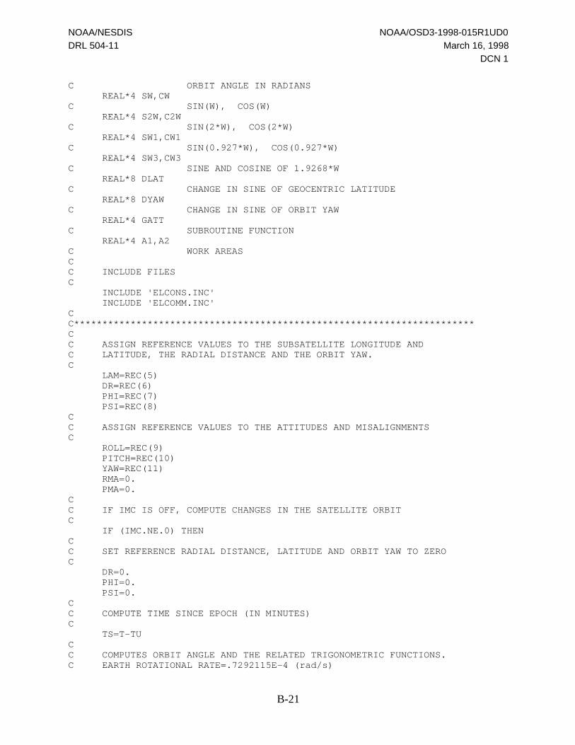
NOAA/NESDIS NOAA/OSD3-1998-015R1UD0
DRL 504-11 March 16, 1998
DCN 1
B-21
C ORBIT ANGLE IN RADIANS REAL*4 SW,CWC SIN(W), COS(W) REAL*4 S2W,C2WC SIN(2*W), COS(2*W) REAL*4 SW1,CW1C SIN(0.927*W), COS(0.927*W) REAL*4 SW3,CW3C SINE AND COSINE OF 1.9268*W REAL*8 DLATC CHANGE IN SINE OF GEOCENTRIC LATITUDE REAL*8 DYAWC CHANGE IN SINE OF ORBIT YAW REAL*4 GATTC SUBROUTINE FUNCTION REAL*4 A1,A2C WORK AREASCC INCLUDE FILESC INCLUDE 'ELCONS.INC' INCLUDE 'ELCOMM.INC'CC***********************************************************************CC ASSIGN REFERENCE VALUES TO THE SUBSATELLITE LONGITUDE ANDC LATITUDE, THE RADIAL DISTANCE AND THE ORBIT YAW.C LAM=REC(5) DR=REC(6) PHI=REC(7) PSI=REC(8)CC ASSIGN REFERENCE VALUES TO THE ATTITUDES AND MISALIGNMENTSC ROLL=REC(9) PITCH=REC(10) YAW=REC(11) RMA=0. PMA=0.CC IF IMC IS OFF, COMPUTE CHANGES IN THE SATELLITE ORBITC IF (IMC.NE.0) THENCC SET REFERENCE RADIAL DISTANCE, LATITUDE AND ORBIT YAW TO ZEROC DR=0. PHI=0. PSI=0.CC COMPUTE TIME SINCE EPOCH (IN MINUTES)C TS=T-TUCC COMPUTES ORBIT ANGLE AND THE RELATED TRIGONOMETRIC FUNCTIONS.C EARTH ROTATIONAL RATE=.7292115E-4 (rad/s)

NOAA/NESDIS NOAA/OSD3-1998-015R1UD0
DRL 504-11 March 16, 1998
DCN 1
B-22
C W=0.7292115D-4*60.0D0*TS SW=SIN(W) CW=COS(W) SW1=SIN(0.927*W) CW1=COS(0.927*W) S2W=SIN(2.*W) C2W=COS(2.*W) SW3=SIN(1.9268*W) CW3=COS(1.9268*W)CC COMPUTES CHANGE IN THE IMC LONGITUDE FROM THE REFERENCEC LAM=LAM+REC(18)+(REC(19)+REC(20)*W)*W 1 +(REC(27)*SW1+REC(28)*CW1+REC(21)*SW+REC(22)*CW 2 +REC(23)*S2W+REC(24)*C2W + REC(25)*SW3+REC(26)*CW3 3 +W*(REC(29)*SW+REC(30)*CW))*2.CC COMPUTES CHANGE IN RADIAL DISTANCE FROM THE REFERENCE (KM)C DR=DR + REC(31) + REC(32)*CW+REC(33)*SW 1 +REC(34)*C2W+REC(35)*S2W + REC(36)*CW3+REC(37)*SW3 2 +REC(38)*CW1+REC(39)*SW1 + W*(REC(40)*CW+REC(41)*SW)CC COMPUTES THE SINE OF THE CHANGE IN THE GEOCENTRIC LATITUDEC DLAT=REC(42) + REC(43)*CW+REC(44)*SW 1 +REC(45)*C2W+REC(46)*S2W 2 +W*(REC(47)*CW+REC(48)*SW) 3 +REC(49)*CW1+REC(50)*SW1CC COMPUTES GEOCENTRIC LATITUDE BY USING AN EXPANSION FOR ARCSINEC PHI=PHI+DLAT*(1.+DLAT*DLAT/6.)CC COMPUTES SINE OF THE CHANGE IN THE ORBIT YAWC DYAW=REC(51) + REC(52)*SW+REC(53)*CW 1 +REC(54)*S2W+REC(55)*C2W 2 +W*(REC(56)*SW+REC(57)*CW) 3 +REC(58)*SW1+REC(59)*CW1CC COMPUTES THE ORBIT YAW BY USING AN EXPANSION FOR ARCSINE.C PSI=PSI+DYAW*(1.+DYAW*DYAW/6.)CC CALCULATION OF CHANGES IN THE SATELLITE ORBIT ENDS HEREC END IFCC CONVERSION OF THE IMC LONGITUDE AND ORBIT YAW TO THE SUBSATELLITEC LONGITUDE AND THE ORBIT INCLINATION (REF: GOES-PCC-TM-2473, INPUTSC REQUIRED FOR EARTH LOCATION AND GRIDDING BY SPS, JUNE 6, 1988)C SLAT=SIN(PHI) SYAW=SIN(PSI) SI=SLAT**2+SYAW**2

NOAA/NESDIS NOAA/OSD3-1998-015R1UD0
DRL 504-11 March 16, 1998
DCN 1
B-23
CI=SQRT(1.-SI) SI=SQRT(SI) IF (SLAT.EQ.0. .AND. SYAW.EQ.0.) THEN U=0. ELSE U=ATAN2(SLAT,SYAW) END IF SU=SIN(U) CU=COS(U)CC COMPUTES LONGITUDE OF THE ASCENDING NODEC ASC=LAM-U SA=SIN(ASC) CA=COS(ASC)CC COMPUTES THE SUBSATELLITE GEOGRAPHIC LATITUDEC RLAT=ATAN(AEBE2*TAN(PHI))CC COMPUTES THE SUBSATELLITE LONGITUDEC RLON=ASC+ATAN2(CI*SU,CU)CC COMPUTES THE SPACECRAFT TO EARTH-FIXED COORDINATES TRANSFORMATIONC MATRIX:C (VECTOR IN ECEF COORDINATES) = B * (VECTOR IN S/C COORDINATES)C B(1,2)=-SA*SI B(2,2)= CA*SI B(3,2)=-CI B(1,3)=-CA*CU+SA*SU*CI B(2,3)=-SA*CU-CA*SU*CI B(3,3)=-SLAT B(1,1)=-CA*SU-SA*CU*CI B(2,1)=-SA*SU+CA*CU*CI B(3,1)= CU*SICC COMPUTES THE NORMALIZED SPACECRAFT POSITION VECTOR IN EARTH-FIXEDC COORDINATES - XS.C R=(NOMORB+DR)/AE XS(1)=-B(1,3)*R XS(2)=-B(2,3)*R XS(3)=-B(3,3)*RCC PRECOMPUTES Q3 (USED IN LPOINT)C Q3=XS(1)**2+XS(2)**2+AEBE2*XS(3)**2-1.0CC COMPUTES THE ATTITUDES AND MISALIGNMENTS IF IMC IS OFFC IF (IMC.NE.0) THENCC COMPUTES THE SOLAR ORBIT ANGLEC WA=REC(60)*TS

NOAA/NESDIS NOAA/OSD3-1998-015R1UD0
DRL 504-11 March 16, 1998
DCN 1
B-24
CC COMPUTES THE DIFFERENCE BETWEEN CURRENT TIME, TS, AND THEC EXPONENTIAL TIME, REC(61). NOTE THAT BOTH TIMES ARE SINCE EPOCH.C TE=TS-REC(61)CC COMPUTES ROLLC ROLL=ROLL+GATT(62,REC,WA,TE)CC COMPUTES PITCHC PITCH=PITCH+GATT(117,REC,WA,TE)CC COMPUTES YAWC YAW=YAW+GATT(172,REC,WA,TE)CC COMPUTES ROLL MISALIGNMENTC RMA=GATT(227,REC,WA,TE)CC COMPUTES PITCH MISALIGNMENTC PMA=GATT(282,REC,WA,TE)CC APPLY THE SPACECRAFT COMPENSATIONC ROLL=ROLL+REC(15) PITCH=PITCH+REC(16) YAW=YAW+REC(17) END IFCC COMPUTES THE INSTRUMENT TO EARTH-FIXED COORDINATES TRANSFORMATIONC MATRIX - BTC CALL INST2ER(ROLL,PITCH,YAW,B,BT) RETURN END
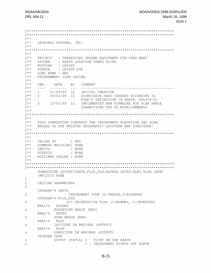
NOAA/NESDIS NOAA/OSD3-1998-015R1UD0
DRL 504-11 March 16, 1998
DCN 1
B-25
C***********************************************************************C***********************************************************************C**C** INTEGRAL SYSTEMS, INC.C**C***********************************************************************C**C** PROJECT : OPERATIONS GROUND EQUIPMENT FOR GOES-NEXTC** SYSTEM : EARTH LOCATION USERS GUIDEC** ROUTINE : LPOINTC** SOURCE : LPOINT.FORC** LOAD NAME : ANYC** PROGRAMMER: IGOR LEVINEC**C** VER. DATA BY COMMENTC** ---- -------- --- ---------------------------------------------C** 1 01/09/89 IL INITIAL CREATIONC** 2 06/02/89 IL COORDINATE AXES CHANGED ACCORDING TOC** FORD'S DEFINITION IN SDAIP, DRL504-01C** 3 12/01/93 IL IMPLEMENTED NEW FORMULAE FOR SCAN ANGLEC** CORRECTIONS DUE TO MISALIGNMENTSC**C***********************************************************************C**C** THIS SUBROUTINE CONVERTS THE INSTRUMENT ELEVATION AND SCANC** ANGLES TO THE RELATED GEOGRAPHIC LATITUDE AND LONGITUDE.C**C***********************************************************************C**C** CALLED BY : ANYC** COMMONS MODIFIED: NONEC** INPUTS : NONEC** OUTPUTS : NONEC** ROUTINES CALLED : NONEC**C***********************************************************************C*********************************************************************** SUBROUTINE LPOINT(INSTR,FLIP_FLG,ALPHA0,ZETA0,RLAT,RLON,IERR) IMPLICIT NONECC CALLING PARAMETERSC INTEGER*4 INSTRC INSTRUMENT CODE (1=IMAGER,2=SOUNDER) INTEGER*4 FLIP_FLGC S/C ORIENTATION FLAG (1=NORMAL,-1=INVERTED) REAL*4 ALPHA0c ELEVATION ANGLE (RAD) REAL*4 ZETA0c SCAN ANGLE (RAD) REAL*4 RLATc LATITUDE IN RADIANS (OUTPUT) REAL*4 RLONc LONGITUDE IN RADIANS (OUTPUT) INTEGER IERRc OUTPUT STATUS; 0 - POINT ON THE EARTHc 1 - INSTRUMENT POINTS OFF EARTH
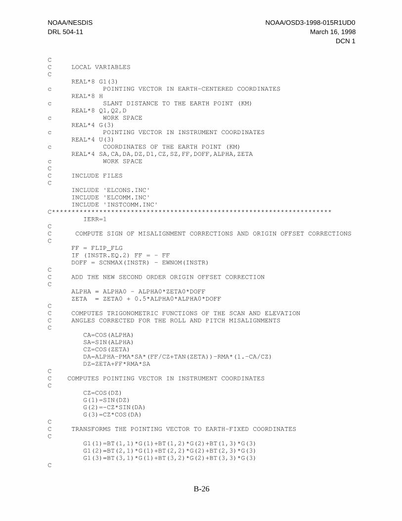
NOAA/NESDIS NOAA/OSD3-1998-015R1UD0
DRL 504-11 March 16, 1998
DCN 1
B-26
CC LOCAL VARIABLESC REAL*8 G1(3)c POINTING VECTOR IN EARTH-CENTERED COORDINATES REAL*8 Hc SLANT DISTANCE TO THE EARTH POINT (KM) REAL*8 Q1,Q2,Dc WORK SPACE REAL*4 G(3)c POINTING VECTOR IN INSTRUMENT COORDINATES REAL*4 U(3)c COORDINATES OF THE EARTH POINT (KM) REAL*4 SA,CA,DA,DZ,D1,CZ,SZ,FF,DOFF,ALPHA,ZETAc WORK SPACECC INCLUDE FILESC INCLUDE 'ELCONS.INC' INCLUDE 'ELCOMM.INC' INCLUDE 'INSTCOMM.INC'C*********************************************************************** IERR=1CC COMPUTE SIGN OF MISALIGNMENT CORRECTIONS AND ORIGIN OFFSET CORRECTIONSC FF = FLIP_FLG IF (INSTR.EQ.2) FF = - FF DOFF = SCNMAX(INSTR) - EWNOM(INSTR)CC ADD THE NEW SECOND ORDER ORIGIN OFFSET CORRECTIONC ALPHA = ALPHA0 - ALPHA0*ZETA0*DOFF ZETA = ZETA0 + 0.5*ALPHA0*ALPHA0*DOFFCC COMPUTES TRIGONOMETRIC FUNCTIONS OF THE SCAN AND ELEVATIONC ANGLES CORRECTED FOR THE ROLL AND PITCH MISALIGNMENTSC CA=COS(ALPHA) SA=SIN(ALPHA) CZ=COS(ZETA) DA=ALPHA-PMA*SA*(FF/CZ+TAN(ZETA))-RMA*(1.-CA/CZ) DZ=ZETA+FF*RMA*SACC COMPUTES POINTING VECTOR IN INSTRUMENT COORDINATESC CZ=COS(DZ) G(1)=SIN(DZ) G(2)=-CZ*SIN(DA) G(3)=CZ*COS(DA)CC TRANSFORMS THE POINTING VECTOR TO EARTH-FIXED COORDINATESC G1(1)=BT(1,1)*G(1)+BT(1,2)*G(2)+BT(1,3)*G(3) G1(2)=BT(2,1)*G(1)+BT(2,2)*G(2)+BT(2,3)*G(3) G1(3)=BT(3,1)*G(1)+BT(3,2)*G(2)+BT(3,3)*G(3)C

NOAA/NESDIS NOAA/OSD3-1998-015R1UD0
DRL 504-11 March 16, 1998
DCN 1
B-27
C COMPUTES COEFFICIENTS AND SOLVES A QUADRATIC EQUATION TOC FIND THE INTERSECT OF THE POINTING VECTOR WITH THE EARTHC SURFACEC Q1=G1(1)**2+G1(2)**2+AEBE2*G1(3)**2 Q2=XS(1)*G1(1)+XS(2)*G1(2)+AEBE2*XS(3)*G1(3) D=Q2*Q2-Q1*Q3 IF (DABS(D).LT.1.D-9) D=0.CC IF THE DISCIMINANTE OF THE EQUATION, D, IS NEGATIVE, THEC INSTRUMENT POINTS OFF THE EARTHC IF (D.LT.0) THEN RLAT=999999. RLON=999999. RETURN END IF D=DSQRT(D)CC SLANT DISTANCE FROM THE SATELLITE TO THE EARTH POINTC H=-(Q2+D)/Q1CC CARTESIAN COORDINATES OF THE EARTH POINTC U(1)=XS(1)+H*G1(1) U(2)=XS(2)+H*G1(2) U(3)=XS(3)+H*G1(3)CC SINUS OF GEOCENTRIC LATITUDEC D1=U(3)/SQRT(U(1)**2+U(2)**2+U(3)**2)CC GEOGRAPHIC (GEODETIC) COORDINATES OF THE POINTC RLAT=ATAN(AEBE2*D1/SQRT(1.-D1*D1)) RLON=ATAN2(U(2),U(1)) IERR=0 RETURN END
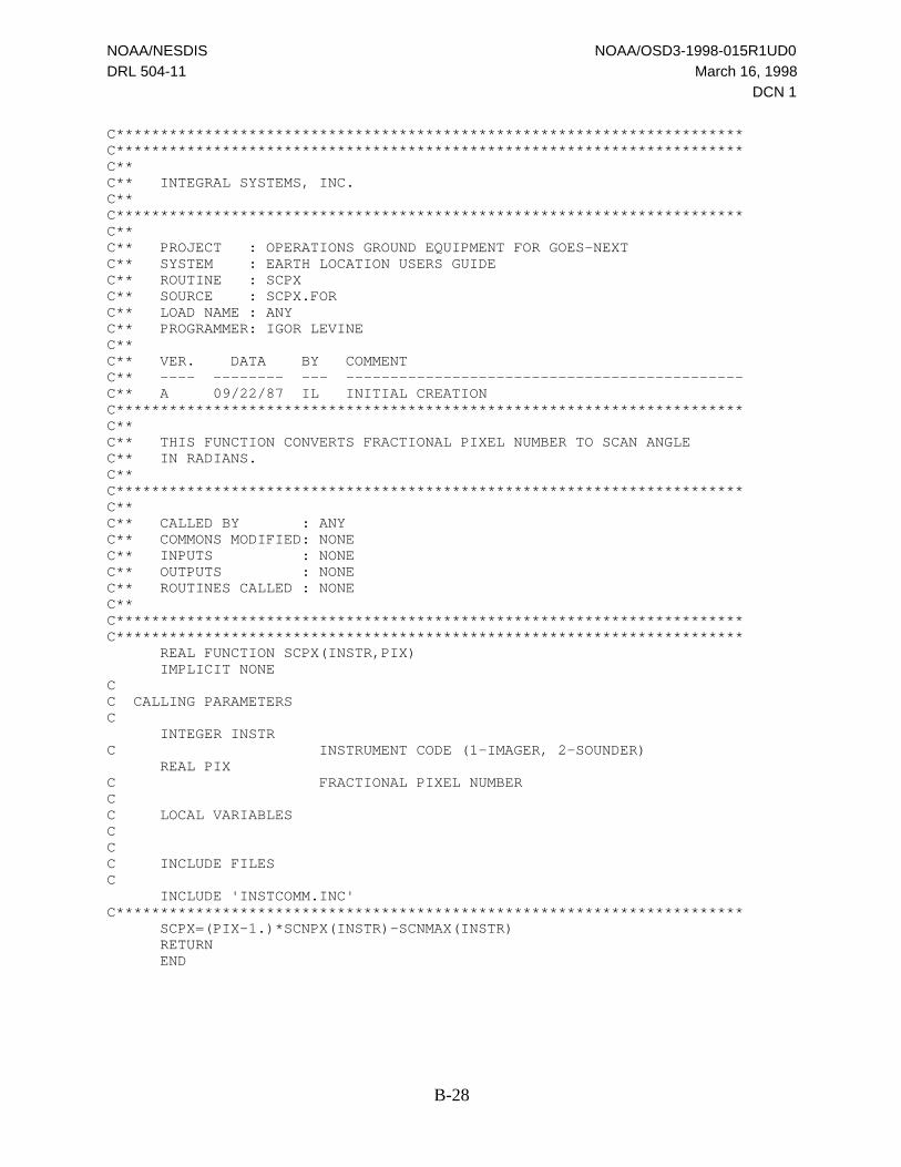
NOAA/NESDIS NOAA/OSD3-1998-015R1UD0
DRL 504-11 March 16, 1998
DCN 1
B-28
C***********************************************************************C***********************************************************************C**C** INTEGRAL SYSTEMS, INC.C**C***********************************************************************C**C** PROJECT : OPERATIONS GROUND EQUIPMENT FOR GOES-NEXTC** SYSTEM : EARTH LOCATION USERS GUIDEC** ROUTINE : SCPXC** SOURCE : SCPX.FORC** LOAD NAME : ANYC** PROGRAMMER: IGOR LEVINEC**C** VER. DATA BY COMMENTC** ---- -------- --- ---------------------------------------------C** A 09/22/87 IL INITIAL CREATIONC***********************************************************************C**C** THIS FUNCTION CONVERTS FRACTIONAL PIXEL NUMBER TO SCAN ANGLEC** IN RADIANS.C**C***********************************************************************C**C** CALLED BY : ANYC** COMMONS MODIFIED: NONEC** INPUTS : NONEC** OUTPUTS : NONEC** ROUTINES CALLED : NONEC**C***********************************************************************C*********************************************************************** REAL FUNCTION SCPX(INSTR,PIX) IMPLICIT NONECC CALLING PARAMETERSC INTEGER INSTRC INSTRUMENT CODE (1-IMAGER, 2-SOUNDER) REAL PIXC FRACTIONAL PIXEL NUMBERCC LOCAL VARIABLESCCC INCLUDE FILESC INCLUDE 'INSTCOMM.INC'C*********************************************************************** SCPX=(PIX-1.)*SCNPX(INSTR)-SCNMAX(INSTR) RETURN END

NOAA/NESDIS NOAA/OSD3-1998-015R1UD0
DRL 504-11 March 16, 1998
DCN 1
B-29
C***********************************************************************C***********************************************************************C**C** INTEGRAL SYSTEMS, INC.C**C***********************************************************************C**C** PROJECT : OPERATIONS GROUND EQUIPMENT FOR GOES-NEXTC** SYSTEM : EARTH LOCATION USERS GUIDEC** ROUTINE : SETCONSC** SOURCE : SETCONS.FORC** LOAD NAME : ANYC** PROGRAMMER: IGOR LEVINEC**C** VER. DATA BY COMMENTC** ---- -------- --- ---------------------------------------------C** 1 02/16/89 IL INITIAL CREATIONC** 2 05/27/94 IL ADDED ARGUMENTS NSCYC1,..,EWINC2C**C***********************************************************************C**C** THIS SUBROUTINE GENERATES CONSTANTS IN COMMON INSTCOMMC**C***********************************************************************C**C** CALLED BY : ANYC** COMMONS MODIFIED: INSTCOMMC** INPUTS : NONEC** OUTPUTS : NONEC** ROUTINES CALLED : NONEC**C***********************************************************************C*********************************************************************** SUBROUTINE SETCONS(NSCYC1, NSINC1, EWCYC1, EWINC1, 1 NSCYC2, NSINC2, EWCYC2, EWINC2) IMPLICIT NONECC CALLING PARAMETERSC INTEGER NSCYC1C N-S CYCLES OF THE IMAGER OFFSET INTEGER NSINC1C N-S INCREMENTS OF THE IMAGER OFFSET INTEGER EWCYC1C E-W CYCLES OF THE IMAGER OFFSET INTEGER EWINC1C E-W INCREMENTS OF THE IMAGER OFFSET INTEGER NSCYC2C N-S CYCLES OF THE SOUNDER OFFSET INTEGER NSINC2C N-S INCREMENTS OF THE SOUNDER OFFSET INTEGER EWCYC2C E-W CYCLES OF THE SOUNER OFFSET INTEGER EWINC2C E-W INCREMENTS OF THE SOUNDER OFFSETCC LOCAL VARIABLES
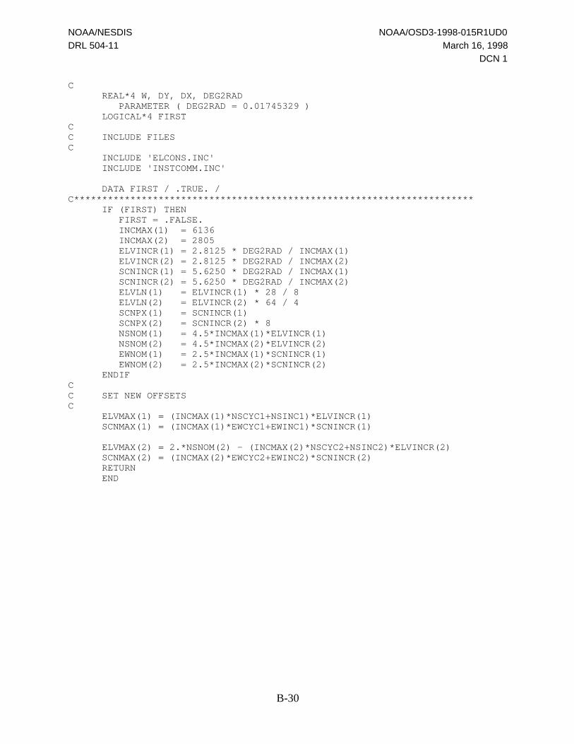
NOAA/NESDIS NOAA/OSD3-1998-015R1UD0
DRL 504-11 March 16, 1998
DCN 1
B-30
C REAL*4 W, DY, DX, DEG2RAD PARAMETER ( DEG2RAD = 0.01745329 ) LOGICAL*4 FIRSTCC INCLUDE FILESC INCLUDE 'ELCONS.INC' INCLUDE 'INSTCOMM.INC'
DATA FIRST / .TRUE. /C*********************************************************************** IF (FIRST) THEN FIRST = .FALSE. INCMAX(1) = 6136 INCMAX(2) = 2805 ELVINCR(1) = 2.8125 * DEG2RAD / INCMAX(1) ELVINCR(2) = 2.8125 * DEG2RAD / INCMAX(2) SCNINCR(1) = 5.6250 * DEG2RAD / INCMAX(1) SCNINCR(2) = 5.6250 * DEG2RAD / INCMAX(2) ELVLN(1) = ELVINCR(1) * 28 / 8 ELVLN(2) = ELVINCR(2) * 64 / 4 SCNPX(1) = SCNINCR(1) SCNPX(2) = SCNINCR(2) * 8 NSNOM(1) = 4.5*INCMAX(1)*ELVINCR(1) NSNOM(2) = 4.5*INCMAX(2)*ELVINCR(2) EWNOM(1) = 2.5*INCMAX(1)*SCNINCR(1) EWNOM(2) = 2.5*INCMAX(2)*SCNINCR(2) ENDIFCC SET NEW OFFSETSC ELVMAX(1) = (INCMAX(1)*NSCYC1+NSINC1)*ELVINCR(1) SCNMAX(1) = (INCMAX(1)*EWCYC1+EWINC1)*SCNINCR(1)
ELVMAX(2) = 2.*NSNOM(2) - (INCMAX(2)*NSCYC2+NSINC2)*ELVINCR(2) SCNMAX(2) = (INCMAX(2)*EWCYC2+EWINC2)*SCNINCR(2) RETURN END
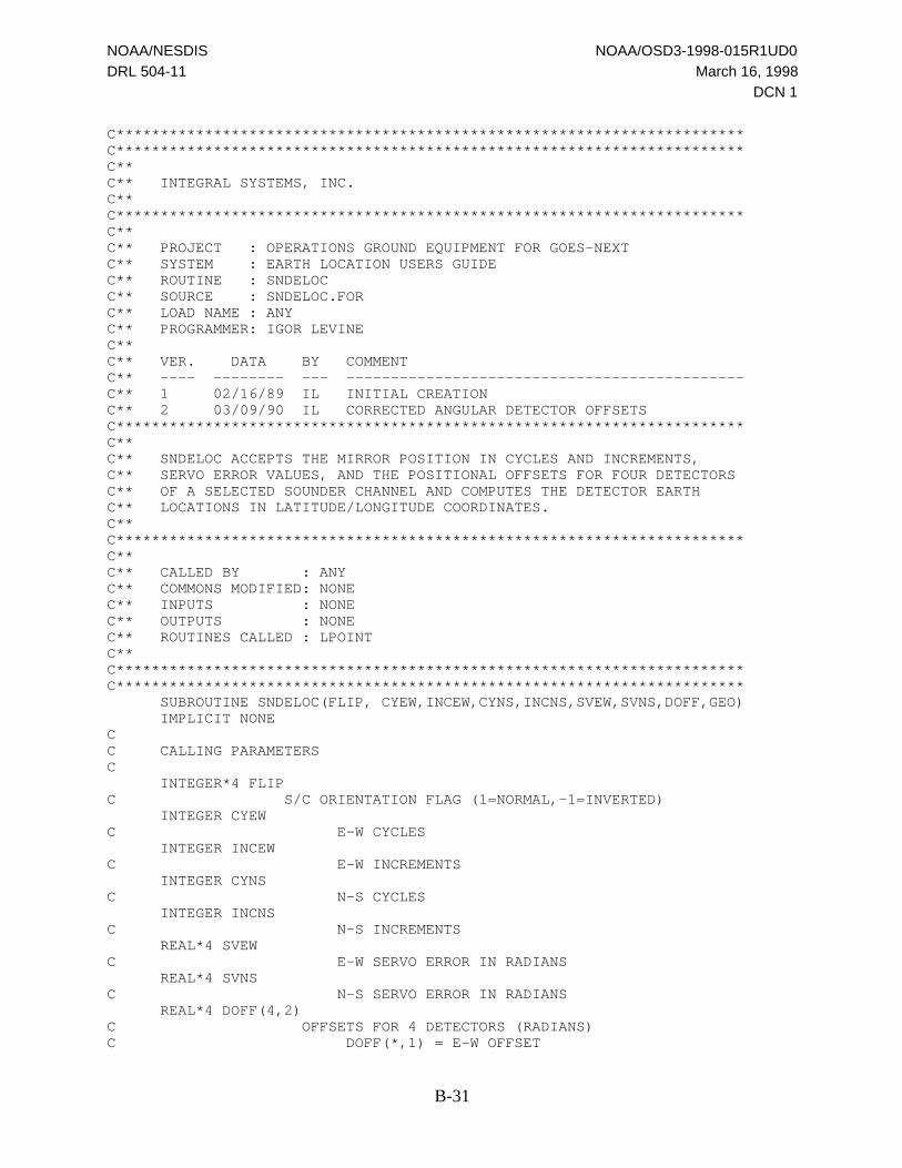
NOAA/NESDIS NOAA/OSD3-1998-015R1UD0
DRL 504-11 March 16, 1998
DCN 1
B-31
C***********************************************************************C***********************************************************************C**C** INTEGRAL SYSTEMS, INC.C**C***********************************************************************C**C** PROJECT : OPERATIONS GROUND EQUIPMENT FOR GOES-NEXTC** SYSTEM : EARTH LOCATION USERS GUIDEC** ROUTINE : SNDELOCC** SOURCE : SNDELOC.FORC** LOAD NAME : ANYC** PROGRAMMER: IGOR LEVINEC**C** VER. DATA BY COMMENTC** ---- -------- --- ---------------------------------------------C** 1 02/16/89 IL INITIAL CREATIONC** 2 03/09/90 IL CORRECTED ANGULAR DETECTOR OFFSETSC***********************************************************************C**C** SNDELOC ACCEPTS THE MIRROR POSITION IN CYCLES AND INCREMENTS,C** SERVO ERROR VALUES, AND THE POSITIONAL OFFSETS FOR FOUR DETECTORSC** OF A SELECTED SOUNDER CHANNEL AND COMPUTES THE DETECTOR EARTHC** LOCATIONS IN LATITUDE/LONGITUDE COORDINATES.C**C***********************************************************************C**C** CALLED BY : ANYC** COMMONS MODIFIED: NONEC** INPUTS : NONEC** OUTPUTS : NONEC** ROUTINES CALLED : LPOINTC**C***********************************************************************C*********************************************************************** SUBROUTINE SNDELOC(FLIP, CYEW,INCEW,CYNS,INCNS,SVEW,SVNS,DOFF,GEO) IMPLICIT NONECC CALLING PARAMETERSC INTEGER*4 FLIPC S/C ORIENTATION FLAG (1=NORMAL,-1=INVERTED) INTEGER CYEWC E-W CYCLES INTEGER INCEWC E-W INCREMENTS INTEGER CYNSC N-S CYCLES INTEGER INCNSC N-S INCREMENTS REAL*4 SVEWC E-W SERVO ERROR IN RADIANS REAL*4 SVNSC N-S SERVO ERROR IN RADIANS REAL*4 DOFF(4,2)C OFFSETS FOR 4 DETECTORS (RADIANS)C DOFF(*,1) = E-W OFFSET
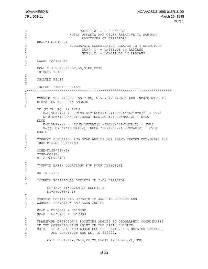
NOAA/NESDIS NOAA/OSD3-1998-015R1UD0
DRL 504-11 March 16, 1998
DCN 1
B-32
C DOFF(*,2) = N-S OFFSETC NOTE: OFFSETS ARE GIVEN RELATIVE TO NOMINALC POSITIONS OF DETECTORS REAL*4 GEO(4,2)C GEOGRAPHIC COORDINATES RELATED TO 4 DETECTORSC GEO(*,1) = LATITUDE IN RADIANSC GEO(*,2) = LONGITUDE IN RADIANSCC LOCAL VARIABLESC REAL E,S,H,EV,SC,DE,DS,SINE,COSE INTEGER I,IERCC INCLUDE FILESC INCLUDE 'INSTCOMM.inc'C***********************************************************************CC CONVERT THE MIRROR POSITION, GIVEN IN CYCLES AND INCREMENTS, TOC ELEVATION AND SCAN ANGLESC IF (FLIP .EQ. 1) THEN E=ELVMAX(2) + ((CYNS-9)*INCMAX(2)+INCNS)*ELVINCR(2) + SVNS S=(CYEW*INCMAX(2)+INCEW)*SCNINCR(2)-SCNMAX(2) + SVEW ELSE E=ELVMAX(2) - (CYNS*INCMAX(2)+INCNS)*ELVINCR(2) - SVNS S=((5-CYEW)*INCMAX(2)-INCEW)*SCNINCR(2)-SCNMAX(2) - SVEW ENDIFCC CORRECT ELEVATION AND SCAN ANGLES FOR SERVO ERRORS OBTAINING THEC TRUE MIRROR POINTINGC SINE=FLIP*SIN(E) COSE=COS(E) H=-2.*SCNPX(2)CC COMPUTE EARTH LOCATIONS FOR FOUR DETECTORSC DO 10 I=1,4CC COMPUTE POSITIONAL OFFSETS OF I-TH DETECTORC DE=(2.5-I)*ELVLN(2)+DOFF(I,2) DS=H+DOFF(I,1)CC CONVERT POSITIONAL OFFSETS TO ANGULAR OFFSETS ANDC CORRECT ELEVATION AND SCAN ANGLESC EV=E + DE*COSE + DS*SINE SC=S - DE*SINE + DS*COSECC TRANSFORM DETECTOR'S POINTING ANGLES TO GEOGRAPHIC COORDINATESC OF THE CORRESPONDING POINT ON THE EARTH SURFACE.C NOTE: IF A DETECTOR LOOKS OFF THE EARTH, THE RELATED LATITUDEC AND LONGITUDE ARE SET TO 999999.C CALL LPOINT(2,FLIP,EV,SC,GEO(I,1),GEO(I,2),IER)

NOAA/NESDIS NOAA/OSD3-1998-015R1UD0
DRL 504-11 March 16, 1998
DCN 1
B-33
H=-H 10 CONTINUE RETURN END

NOAA/NESDIS NOAA/OSD3-1998-015R1UD0
DRL 504-11 March 16, 1998
DCN 1
B-34
C***********************************************************************C***********************************************************************C**C** INTEGRAL SYSTEMS, INC.C**C***********************************************************************C**C** PROJECT : OPERATIONS GROUND EQUIPMENT FOR GOES-NEXTC** SYSTEM : EARTH LOCATION USERS GUIDEC** NAME : ELCOMMC** TYPE : DATA AREAC** SOURCE : ELCOMM.INCC**C** VER. DATA BY COMMENTC** ---- -------- ---------------- --------------------------------C** A 01/09/89 I. LEVINE INITIAL CREATIONC**C***********************************************************************C**C** DESCRIPTIONC** INSTRUMENT POSITION AND ATTITUDE VARIABLES AND TRANSFORMATIONC** MATRIXC**C***********************************************************************C***********************************************************************CC COMMON VARIABLESC REAL*8 XS(3)C NORMALIZED S/C POSITION IN ECEF COORDINATES REAL*8 BT(3,3)C ECEF TO INSTRUMENT COORDINATES TRANSFORMATION REAL*8 Q3C USED IN SUBROUTINE LPOINT REAL*4 PITCH,ROLL,YAWC PITCH,ROLL,YAW ANGLES OF INSTRUMENT (RAD) REAL*4 PMA,RMAC PITCH,ROLL MISALIGNMENTS OF INSTRUMENT (RAD) COMMON /ELCOMM/ XS,BT,Q3,PITCH,ROLL,YAW,PMA,RMA

NOAA/NESDIS NOAA/OSD3-1998-015R1UD0
DRL 504-11 March 16, 1998
DCN 1
B-35
C***********************************************************************C***********************************************************************C**C** INTEGRAL SYSTEMS, INC.C**C***********************************************************************C**C** PROJECT : OPERATIONS GROUND EQUIPMENT FOR GOES-NEXTC** SYSTEM : EARTH LOCATION USERS GUIDEC** NAME : ELCONSC** TYPE : DATA AREAC** SOURCE : ELCONS.INCC**C** VER. DATA BY COMMENTC** ---- -------- ---------------- --------------------------------C** A 01/09/89 I. LEVINE INITIAL CREATIONC**C***********************************************************************C**C** DESCRIPTIONC** MATHEMATICAL AND EARTH-RELATED CONSTANTSC**C***********************************************************************C***********************************************************************C REAL*8 PI PARAMETER (PI=3.141592653589793D0) REAL*8 DEG PARAMETER (DEG=180.D0/PI) REAL*8 RAD PARAMETER (RAD=PI/180.D0)C DEGREES TO RADIANS CONVERSION PI/180 REAL*8 NOMORB PARAMETER (NOMORB=42164.365D0)C NOMINAL RADIAL DISTANCE OF SATELLITE (km) REAL*8 AE PARAMETER (AE=6378.137D0)C EARTH EQUATORIAL RADIUS (km) REAL*8 FER PARAMETER (FER=1.D0/298.25D0)C EARTH FLATTENING COEFFICIENT = 1-(BE/AE) REAL*4 AEBE2 PARAMETER (AEBE2=1.D0/(1.D0-FER)**2) REAL*4 AEBE3 PARAMETER (AEBE3=AEBE2-1.) REAL*4 AEBE4 PARAMETER (AEBE4=(1.D0-FER)**4-1.)CC***********************************************************************
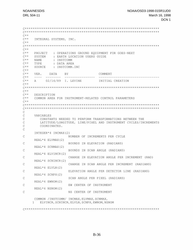
NOAA/NESDIS NOAA/OSD3-1998-015R1UD0
DRL 504-11 March 16, 1998
DCN 1
B-36
C***********************************************************************C***********************************************************************C**C** INTEGRAL SYSTEMS, INC.C**C***********************************************************************C**C** PROJECT : OPERATIONS GROUND EQUIPMENT FOR GOES-NEXTC** SYSTEM : EARTH LOCATION USERS GUIDEC** NAME : INSTCOMMC** TYPE : DATA AREAC** SOURCE : INSTCOMM.INCC**C** VER. DATA BY COMMENTC** ---- -------- ---------------- --------------------------------C** A 02/16/89 I. LEVINE INITIAL CREATIONC**C***********************************************************************C**C** DESCRIPTIONC** COMMON AREA FOR INSTRUMENT-RELATED CONTROL PARAMETERSC**C***********************************************************************C***********************************************************************CC VARIABLESC CONSTANTS NEEDED TO PERFORM TRANSFORMATIONS BETWEEN THEC LATITUDE/LONGITUDE, LINE/PIXEL AND INSTRUMENT CYCLES/INCREMENTSC COORDINATES.C INTEGER*4 INCMAX(2)C NUMBER OF INCREMENTS PER CYCLE REAL*4 ELVMAX(2)C BOUNDS IN ELEVATION (RADIANS) REAL*4 SCNMAX(2)C BOUNDS IN SCAN ANGLE (RADIANS) REAL*4 ELVINCR(2)C CHANGE IN ELEVATION ANGLE PER INCREMENT (RAD) REAL*4 SCNINCR(2)C CHANGE IN SCAN ANGLE PER INCREMENT (RADIANS) REAL*4 ELVLN(2)C ELEVATION ANGLE PER DETECTOR LINE (RADIANS) REAL*4 SCNPX(2)C SCAN ANGLE PER PIXEL (RADIANS) REAL*4 EWNOM(2)C EW CENTER OF INSTRUMENT REAL*4 NSNOM(2)C NS CENTER OF INSTRUMENT
COMMON /INSTCOMM/ INCMAX,ELVMAX,SCNMAX, 1 ELVINCR,SCNINCR,ELVLN,SCNPX,EWNOM,NSNOM
C***********************************************************************

NOAA/NESDIS NOAA/OSD3-1998-015R1UD0
DRL 504-11 March 16, 1998
DCN 1
B-37
C***********************************************************************C***********************************************************************C**C** INTEGRAL SYSTEMS, INC.C**C***********************************************************************C**C** PROJECT : OPERATIONS GROUND EQUIPMENT FOR GOES-NEXTC** SYSTEM : EARTH LOCATION USERS GUIDEC** NAME : RECC** TYPE : DATA AREAC** SOURCE : ELREC.INCC**C** VER. DATA BY COMMENTC** ---- -------- ---------------- --------------------------------C** A 01/19/89 I. LEVINE INITIAL CREATIONC**C***********************************************************************C**C** DESCRIPTIONC** TEST SET OF O&A PARAMETERS IN THE GVAR BLOCK 0 FORMATC**C***********************************************************************C***********************************************************************C CONTENT OF CORRESPONDING WORDS:C REC(5) - REFERENCE LONGITUDEC REC(6) - DISTANCE FROM NOMINALC REC(7) - REFERENCE LATITUDEC REC(8) - REFERENCE ORBIT YAWC REC(9) - REFERENCE ROLLC REC(10) - REFERENCE PITCHC REC(11) - REFERENCE YAWC REC(12),REC(13) - EPOCH TIME IN THE BCD FORMAT /YYYYDDDH HMMSSLLL/C WHERE Y=YEAR, D=DAY, H=HOUR, M=MINUTE,C S=SECONDS, L=MILLISECONDS.C REC(14) - UNUSEDC REC(15) - SPACECRAFT COMPENSATION, ROLLC REC(16) - SPACECRAFT COMPENSATION, PITCHC REC(17) - SPACECRAFT COMPENSATION, YAWC REC(62) - ROLL COEFFICIENTS BEGIN HEREC REC(117) - PITCH COEFFICIENTS BEGIN HEREC REC(172) - YAW COEFFICIENTS BEGIN HEREC REC(227) - ROLL MISALIGNMENT COEFFICIENTS BEGIN HEREC REC(282) - PITCH MISALIGNMENT COEFFICIENTS BEGIN HEREC*********************************************************************** REAL*4 REC(336) DATA REC/4*0,C REFER. LON=-100.1189, LAT=-1.9813, ORB.YAW=-.34967 deg, DIST=84.066 1 -1.747405052185, 84.06604003906, -.34368492669E-1, 1 -.6102979183197E-2, 3*0,C EPOCH 02/01/89 6:29:34.567 1 X'19890320',X'62934567',C SPECECRAFT COMPENSATION 1 0,3.E-4,-3.E-4,-2.E-4,C COEFFICIENTS FOR CHANGES IN LON, LAT, RADIAL DISTANCE AND ORBIT YAW 1 42*2.E-4,C DAILY SOLAR RATE (rad/min) AND EXPONENTIAL START TIME FROM EPOCH
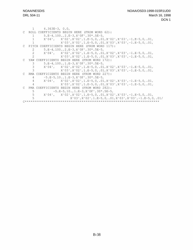
NOAA/NESDIS NOAA/OSD3-1998-015R1UD0
DRL 504-11 March 16, 1998
DCN 1
B-38
1 4.363E-3, 0.0,C ROLL COEFFICIENTS BEGIN HERE (FROM WORD 62): 1 5.E-4,100.,2.E-3,X'0F',30*.5E-5, 1 X'04', X'02',X'02',1.E-5,0,.01,X'02',X'03',-1.E-5,0,.01, 1 X'03',X'02',1.E-5,0,.01,X'03',X'03',-1.E-5,0,.01,C PITCH COEFFICIENTS BEGIN HERE (FROM WORD 117): 2 5.E-4,100.,2.E-3,X'0F',30*.5E-5, 2 X'04', X'02',X'02',1.E-5,0,.01,X'02',X'03',-1.E-5,0,.01, 2 X'03',X'02',1.E-5,0,.01,X'03',X'03',-1.E-5,0,.01,C YAW COEFFICIENTS BEGIN HERE (FROM WORD 172): 3 5.E-4,100.,1.E-3,X'0F',30*.5E-5, 3 X'04', X'02',X'02',1.E-5,0,.01,X'02',X'03',-1.E-5,0,.01, 3 X'03',X'02',1.E-5,0,.01,X'03',X'03',-1.E-5,0,.01,C RMA COEFFICIENTS BEGIN HERE (FROM WORD 227): 4 -5.E-5,10.,1.E-3,X'0F',30*.5E-5, 4 X'04', X'02',X'02',1.E-5,0,.01,X'02',X'03',-1.E-5,0,.01, 4 X'03',X'02',1.E-5,0,.01,X'03',X'03',-1.E-5,0,.01,C PMA COEFFICIENTS BEGIN HERE (FROM WORD 282):
5 -5.E-5,10.,1.E-3,X'0F',30*.5E-5, 5 X'04', X'02',X'02',1.E-5,0,.01,X'02',X'03',-1.E-5,0,.01,
5 X'03',X'02',1.E-5,0,.01,X'03',X'03',-1.E-5,0,.01/C***********************************************************************

NOAA/NESDIS NOAA/OSD3-1998-015R1UD0
DRL 504-11 March 16, 1998
DCN 1
C-1
Appendix C.
Kamel to Keplerian Transformation
See separate file ELUGAPPC.DOC for the contents of this appendix.

NOAA/NESDIS NOAA/OSD3-1998-015R1UD0
DRL 504-11 March 16, 1998
DCN 1
DL-1
Distribution List
Organization Name Address
National Oceanic and Atmospheric Administration (NOAA)
NOAA/SO13 Baker, Michael FB 4, Room 0109NOAA/SO13 Celone, Pete FB 4, Room 0151NOAA/OSD Dittberner, Gerald FB 4, Room 3301NOAA/OSD3 Dorsey, Warren FB 4, Room 3308ANOAA/SO12 Dress, Andre FB 4, Room 0110NOAA/SO13 Goddard, Brent FB 4, Room 0109/0122NOAA/SO13 Han, Dong FB 4, Room 0110NOAA/SO1 Kelly, Kathleen FB 4, Room 0135NOAA/SO13 King, Cheryl FB 4, Room 0109NOAA/SO13 McCoy, Robert FB 4, Room 0109NOAA/OSD3 McKenzie, Keith FB 4, Room 3308DNOAA/SO13 Miller, Dolores FB 4, Room 0109NOAA/SAO4 Miller, Edward GSFC Code 415.0, Bldg. 6, W241NOAA/SO13 Pinkine, Nick FB 4, Room 0110NOAA/OSD3 Reynolds, Richard FB 4, Room 3308CNOAA/SO13 Robinson, Diane FB 4, Room 0109NOAA/SO212 Speidel, William CDA, Wallops, VANOAA/SO1 Suranno, Michael FB 4, Room 0135NOAA/SO13 Tsui, John FB 4, Room 0110NOAA/SO12 Walsh, Timothy FB 4, Room 0110NOAA/ESP3 Winston, Wayne WWB, Suite 200NOAA/SAO4 Wrublewski, Tom GSFC Code 480.0, Bldg. 6, W241NOAA/SOCC Floor Copy, Operator FB 4, 0200 WingNOAA/SOCC Floor Copy, Engineer FB 4, 0200 WingNOAA GOES Library c/o Raza, Haider FB 4, Room 3307NOAA/SOCC Library c/o Rasolee, Niloofar FB 4, Room 0129NOAA/WCDA Library c/o Sheridan, Jim [2] CDA, Wallops, VANOAA/WCDA Floor Copy c/o Sheridan, Jim CDA, Wallops, VANOAA/CSC Dutcher, David FB 4, Room 3311NOAA/CSC Hegele, Linwood FB 4, Room 3313NOAA/CSC Smith, David FB 4, Room 3315ANOAA/CSC Smith, Elizabeth FB 4, Room 3317NOAA/CSC Webber, William FB 4, Room 3314NOAA/CSC Yu, Yan Pong FB 4, Room 3315NOAA/ADNET De Vore, Felicia FB 4, Room 3317NOAA/PRC Hickman, Barbara Camp Springs, MD
National Aeronautics and Space Administration (NASA)
NOAA/NESDIS NOAA/OSD3-1998-015R1UD0
DRL 504-11 March 16, 1998
DCN 1
DL-2
NASA/GSFC Martin, David GSFC Code 415.0, Bldg. 6, W213NASA/GSFC GOES Library c/o Archer, Benita GSFC Code 415.0, Bldg. 6, W232NASA/CSC MOST Library c/o Anderson, Joyce Boeing, Seabrook, MDNASA/CSC Bengston, Charles Boeing, Seabrook, MDNASA/CSC Fiorello, John Boeing, Seabrook, MD
The Aerospace Corporation
Aerospace Pastore, Richard FB 4, Room 3316
Lockheed-Martin – SMS&S
LMSMS&S Al-Jazrawi, Anne FB 4, Room 0109LMSMS&S Al-Jazrawi, Atheer FB 4, Room 0165LMSMS&S Clemons, Eric FB 4, Room 0165LMSMS&S DeGumbia, Jonathan FB 4, Room 0165LMSMS&S Forness, Richard FB 4, Room 0165LMSMS&S Gurlacz, Tom FB 4, Room 0165LMSMS&S Herndon, David FB 4, Room 0109LMSMS&S Kempton, James Seabrook, MDLMSMS&S Riefner, Kurt FB 4, Room 0165LMSMS&S Smith, Brian FB 4, Room 0135; Seabrook, MDLMSMS&S Walker, Greg FB 4, Room 0109LMSMS&S Zegalia, Steve FB 4, Room 0165
Integral Systems, Incorporated (ISI)
ISI Johnson, Joy Lanham, MDISI Race, Randall Lanham, MDISI Reece, Jay Lanham, MDISI Scott, George Lanham, MDISI Walsh, Steve Lanham, MDISI Woods, Patrick Lanham, MD
Space System/Loral (SS/L)
SS/L Chevray, Keiko FB 4, Room 0165SS/L Hudson, James Palo Alto, CASS/L Lutz, Steve Palo Alto, CA
Swales Aerospace)
Swales Arnaud, Daniel Beltsville, MDSwales Baucom, Tina Beltsville, MDSwales Bryant, William Beltsville, MDSwales Finnegan, Eric Beltsville, MD