earth - insulation tester mi 2088 user manual · pdf fileearth - insulation tester mi 2088...
TRANSCRIPT
Earth - Insulation Tester MI 2088
User Manual Version 1.0, Code no. 20 750 325
2
Distributor: Manufacturer: METREL d.d. Ljubljanska cesta 77 1354 Horjul Slovenia web site: http://www.metrel.si e-mail: [email protected]
Mark on your equipment certifies that this equipment meets the requirements of the EU (European Union) concerning safety and interference causing equipment regulations
© 2003 METREL No part of this publication may be reproduced or utilized in any form or by any means without permission in writing from METREL.
MI 2088 Earth –Insulation Tester Table of contents
3
1. Introduction ............................................................................................................ 4 1.1. General description ........................................................................................... 4 1.2. Warnings ........................................................................................................... 5 1.3. List of parameters measurable by the Earth - Insulation Tester ........................ 6 1.4. Standards applied.............................................................................................. 6
2. Instrument description .......................................................................................... 7 2.1. Front panel ........................................................................................................ 7 2.2 Connector panel ................................................................................................. 9 2.3. Bottom side...................................................................................................... 10 2.4. Standard accessories ...................................................................................... 11 2.5. Optional accessories ....................................................................................... 11 2.6. Ways of carrying the instrument ...................................................................... 11
3. Measurement instructions .................................................................................. 12 3.1. Insulation Resistance ...................................................................................... 12 3.2. Voltage ............................................................................................................ 16 3.3. Continuity of Protection Conductors ................................................................ 18 3.4. Continuity ........................................................................................................ 22 3.6. Specific Earth Resistance................................................................................ 31 3.7. Current (True RMS)......................................................................................... 34 3.8. Varistor Over-voltage Protection Devices........................................................ 36
4. Memory and other operations............................................................................. 39 4.1. Storing of test results....................................................................................... 39 4.2. Recalling of stored results ............................................................................... 40 4.3. Erasing of stored results.................................................................................. 42 4.4. RS 232 communication ................................................................................... 42 4.5. Reset of the instrument ................................................................................... 43 4.6. General setings ............................................................................................... 44
5. Maintenance ......................................................................................................... 45 5.1. Batteries .......................................................................................................... 45 5.2. Fuses............................................................................................................... 46 5.3. Cleaning .......................................................................................................... 46 5.4. Periodic calibration .......................................................................................... 47 5.5. Service ............................................................................................................ 47
6. Technical specification........................................................................................ 48 6.1. Functions......................................................................................................... 48 6.2. General characteristics.................................................................................... 50
MI 2088 Earth –Insulation Tester Introduction
4
1. Introduction Congratulations on your purchase of the Earth - Insulation Tester and its accessories, produced by METREL d.d. We are glad, to be able to offer high professional test equipment, for carrying out absolute measurement of Earth Resistances and Insulation Resistances on installations in buildings. The equipment was designed and produced on basis of rich experiences, acquired through more-years long period of dealing with Earth Resistance and Electric installation test equipment. 1.1. General description The Earth - Insulation Tester is high professional, multifunctional, portable test instrument. It is intended for carrying out Earth Resistance, Insulation Resistance and Continuity of Protection Conductors measurements, according to European standard EN 61557. It can also do various other tests and measurements. The instrument is equiped with all accessories, necessary for comfortable carrying out the tests. It is kept in a soft carrying bag, separated from enclosed accessories. Electronic part of the Earth - Insulation Tester is produced in SMD technology, which demands practically no service interventions. Custom designed LCD display with backlight offers easy to read main results as well as a wide range of subresults, parameters and messages. Operatio is simple and clear, operater does not need to attend any special training (except to read this Instruction Manual) to operate the instrument. In order, the operater to be familiar enough with measurements, covered by the Earth – Insulation Tester (purpose of each measurement, measurement principle, limit values etc.), it is advisable to read the enclosed handbook Measurements on electric installations in theory and practice. Professional PC SW enables simple transfer of test results and other parameters to PC, as well as simple and quick forming of final protocols.
MI 2088 Earth –Insulation Tester Introduction
5
1.2. Warnings In order to reach high operater's safety while carrying out various measurements and tests using the Earth - Insulation Tester, as well as to keep the test equipment undamaged, it is necessary to consider the following general warnings: If the test equipment is used in manner not specified in this Instruction Manual, the protection provided by the equipment may be impaired! Do not use the instrument and accessories, if any damage is noticed! In case of blown fuse, follow the instructions in this Instruction Manual, to replace it! Service intervention or calibration procedure is allowed to be carried out only by a competent, authorized person! Consider all generally known precautions, in order to avoid risk of electric shock, while dealing with hazardous voltages! Use only standard or optional test cables, supplied by your dealer!
MI 2088 Earth –Insulation Tester Introduction
6
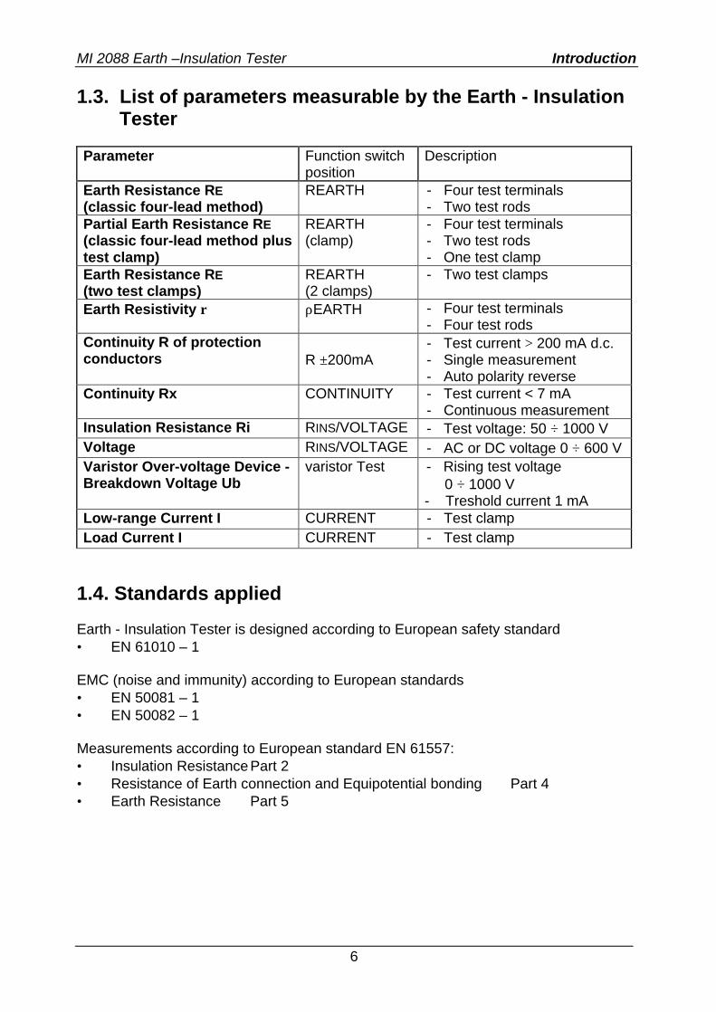
1.3. List of parameters measurable by the Earth - Insulation Tester
Parameter Function switch
position Description
Earth Resistance RE (classic four-lead method)
REARTH - Four test terminals - Two test rods
Partial Earth Resistance RE (classic four-lead method plus test clamp)
REARTH (clamp)
- Four test terminals - Two test rods - One test clamp
Earth Resistance RE (two test clamps)
REARTH (2 clamps)
- Two test clamps
Earth Resistivity ρ ρEARTH - Four test terminals - Four test rods
Continuity R of protection conductors
R ±200mA
- Test current > 200 mA d.c. - Single measurement - Auto polarity reverse
Continuity Rx CONTINUITY - Test current < 7 mA - Continuous measurement
Insulation Resistance Ri RINS/VOLTAGE - Test voltage: 50 ÷ 1000 V Voltage RINS/VOLTAGE - AC or DC voltage 0 ÷ 600 V Varistor Over-voltage Device -Breakdown Voltage Ub
varistor Test - Rising test voltage 0 ÷ 1000 V - Treshold current 1 mA
Low-range Current I CURRENT - Test clamp Load Current I CURRENT - Test clamp
1.4. Standards applied Earth - Insulation Tester is designed according to European safety standard • EN 61010 – 1 EMC (noise and immunity) according to European standards • EN 50081 – 1 • EN 50082 – 1 Measurements according to European standard EN 61557: • Insulation Resistance Part 2 • Resistance of Earth connection and Equipotential bonding Part 4 • Earth Resistance Part 5
MI 2088 Earth –Insulation Tester Instrument description
7
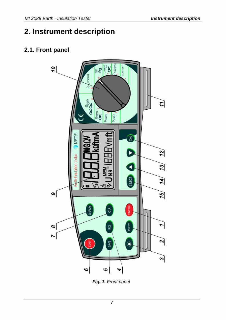
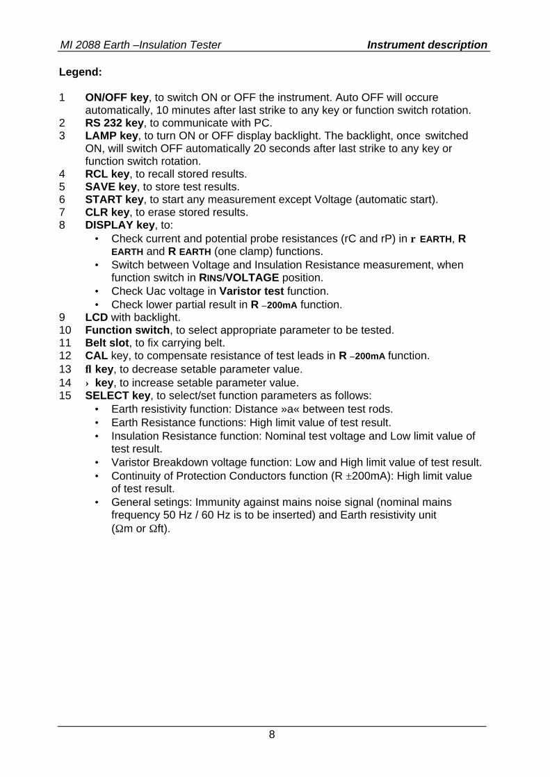
2. Instrument description 2.1. Front panel
Fig. 1. Front panel
MI 2088 Earth –Insulation Tester Instrument description
8
Legend: 1 ON/OFF key, to switch ON or OFF the instrument. Auto OFF will occure
automatically, 10 minutes after last strike to any key or function switch rotation. 2 RS 232 key, to communicate with PC. 3 LAMP key, to turn ON or OFF display backlight. The backlight, once switched
ON, will switch OFF automatically 20 seconds after last strike to any key or function switch rotation.
4 RCL key, to recall stored results. 5 SAVE key, to store test results. 6 START key, to start any measurement except Voltage (automatic start). 7 CLR key, to erase stored results. 8 DISPLAY key, to:
• Check current and potential probe resistances (rC and rP) in ρ EARTH, R EARTH and R EARTH (one clamp) functions.
• Switch between Voltage and Insulation Resistance measurement, when function switch in RINS/VOLTAGE position.
• Check Uac voltage in Varistor test function. • Check lower partial result in R ±200mA function.
9 LCD with backlight. 10 Function switch, to select appropriate parameter to be tested. 11 Belt slot, to fix carrying belt. 12 CAL key, to compensate resistance of test leads in R ±200mA function. 13 ↓ key, to decrease setable parameter value. 14 ↑ key, to increase setable parameter value. 15 SELECT key, to select/set function parameters as follows:
• Earth resistivity function: Distance »a« between test rods. • Earth Resistance functions: High limit value of test result. • Insulation Resistance function: Nominal test voltage and Low limit value of
test result. • Varistor Breakdown voltage function: Low and High limit value of test result. • Continuity of Protection Conductors function (R ±200mA): High limit value
of test result. • General setings: Immunity against mains noise signal (nominal mains
frequency 50 Hz / 60 Hz is to be inserted) and Earth resistivity unit (Ωm or Ωft).
MI 2088 Earth –Insulation Tester Instrument description
9
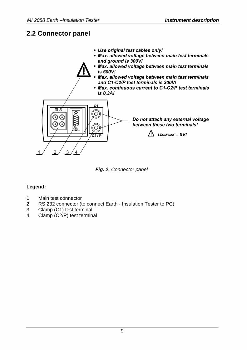
2.2 Connector panel
Fig. 2. Connector panel
Legend: 1 Main test connector 2 RS 232 connector (to connect Earth - Insulation Tester to PC) 3 Clamp (C1) test terminal 4 Clamp (C2/P) test terminal
MI 2088 Earth –Insulation Tester Instrument description
10
2.3. Bottom side
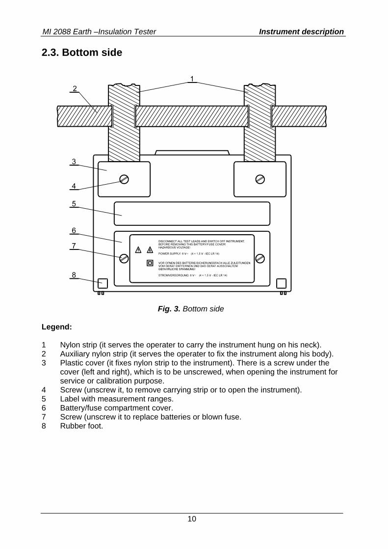
Fig. 3. Bottom side
Legend: 1 Nylon strip (it serves the operater to carry the instrument hung on his neck). 2 Auxiliary nylon strip (it serves the operater to fix the instrument along his body). 3 Plastic cover (it fixes nylon strip to the instrument). There is a screw under the
cover (left and right), which is to be unscrewed, when opening the instrument for service or calibration purpose.
4 Screw (unscrew it, to remove carrying strip or to open the instrument). 5 Label with measurement ranges. 6 Battery/fuse compartment cover. 7 Screw (unscrew it to replace batteries or blown fuse. 8 Rubber foot.
MI 2088 Earth –Insulation Tester Instrument description
11
2.4. Standard accessories See attached sheet, to compare received set of accessories with listed one. 2.5. Optional accessories See attached sheet, to check the list of available optional accessories, which may be supplied upon request.
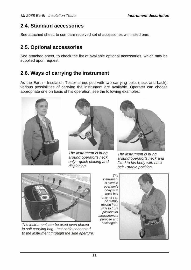
2.6. Ways of carrying the instrument As the Earth - Insulation Tester is equiped with two carrying belts (neck and back), various possibilities of carrying the instrument are available. Operater can choose appropriate one on basis of his operation, see the following examples:
The instrument is hung around operator's neck only - quick placing anddisplacing.
The instrument is hung around operator's neck and fixed to his body with back belt - stable position.
The instrument can be used even placed in soft carrying bag - test cable connectedto the instrument throught the side aperture.
The instrument is fixed to operator's body with back belt
only - it canbe simply
moved from side to frontposition for
measurement purpose andback again.
MI 2088 Earth –Insulation Tester Measurement instructions
12
3. Measurement instructions 3.1. Insulation Resistance There are different objects, where Insulation Resistance is to be measured, in order to assure safety of electric installation and appliances. Let’s list a few examples: • Insulation Resistance between installation conductors L1, L2, L3, N, PE (all • combinations). • Insulation Resistance of non-conductive rooms (walls and floors). • Insulation Resistance of ground cables. • Resistance of semiconductive (antistatic) floors. For additional general information concerning Insulation Resistance measurement, refer to enclosed handbook Measurements on electric installations in practice and theory. Warnings! • Make sure tested object to be deenergized (mains voltage disconnected) before
starting the measurement! • When measuring Insulation Resistance between conductors, all loads must be
disconnected and all switches closed! • Do not touch tested object while testing it, risk of electric schock! • Do not connect test terminals to external voltage higher than 600 V a.c. or d.c.,
in order not to damage the test instrument! • In case of capacitive test object (capacitive compensation of reactive power,
long tested cable etc.), automatic discharge of the object may not be done immediatelly after finishing the measurement. Falling voltage will be displayed in that case – do not disconnect test leads until the voltage drops below 50V!
How to carry out the measurement ? Step 1 • Connect test cable (Split test leads or Tip Commander) to Earth - Insulation
Tester. • Set function switch to RINS, VOLTAGE position, the following menu will be
displayed:
MI 2088 Earth –Insulation Tester Measurement instructions
13
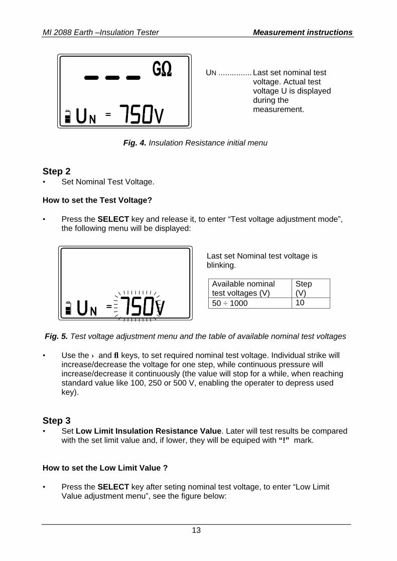
Fig. 4. Insulation Resistance initial menu
Step 2 • Set Nominal Test Voltage. How to set the Test Voltage? • Press the SELECT key and release it, to enter “Test voltage adjustment mode”,
the following menu will be displayed:
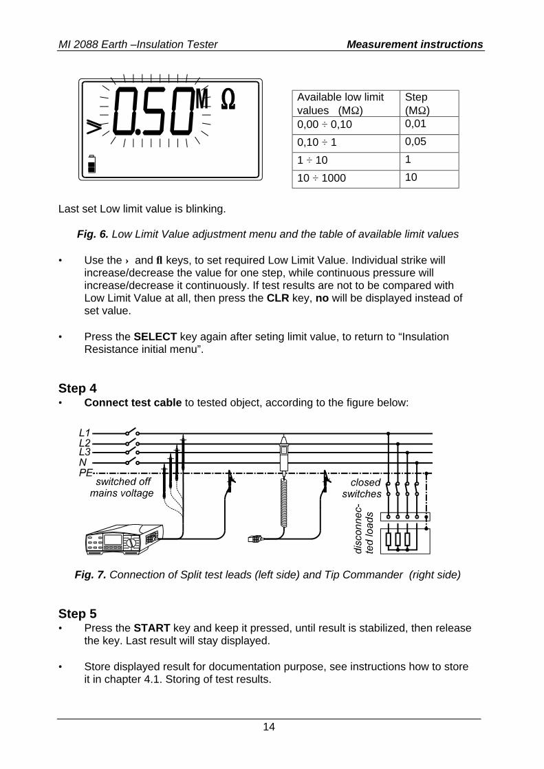
Fig. 5. Test voltage adjustment menu and the table of available nominal test voltages • Use the ↑ and ↓ keys, to set required nominal test voltage. Individual strike will
increase/decrease the voltage for one step, while continuous pressure will increase/decrease it continuously (the value will stop for a while, when reaching standard value like 100, 250 or 500 V, enabling the operater to depress used key).
Step 3 • Set Low Limit Insulation Resistance Value. Later will test results be compared
with the set limit value and, if lower, they will be equiped with “!” mark. How to set the Low Limit Value ? • Press the SELECT key after seting nominal test voltage, to enter “Low Limit
Value adjustment menu”, see the figure below:
UN ............... Last set nominal test voltage. Actual test voltage U is displayed during the measurement.
Last set Nominal test voltage is blinking.
Available nominal test voltages (V)
Step (V)
50 ÷ 1000 10
MI 2088 Earth –Insulation Tester Measurement instructions
14
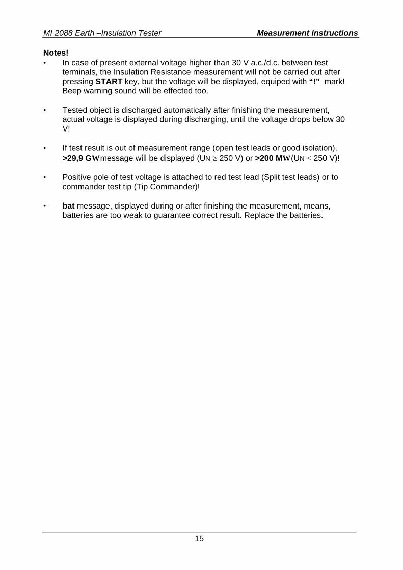
Last set Low limit value is blinking.
Fig. 6. Low Limit Value adjustment menu and the table of available limit values
• Use the ↑ and ↓ keys, to set required Low Limit Value. Individual strike will increase/decrease the value for one step, while continuous pressure will increase/decrease it continuously. If test results are not to be compared with Low Limit Value at all, then press the CLR key, no will be displayed instead of set value.
• Press the SELECT key again after seting limit value, to return to “Insulation
Resistance initial menu”. Step 4 • Connect test cable to tested object, according to the figure below:
Fig. 7. Connection of Split test leads (left side) and Tip Commander (right side)
Step 5 • Press the START key and keep it pressed, until result is stabilized, then release
the key. Last result will stay displayed. • Store displayed result for documentation purpose, see instructions how to store
it in chapter 4.1. Storing of test results.
Available low limit values (MΩ)
Step (MΩ)
0,00 ÷ 0,10 0,01
0,10 ÷ 1 0,05
1 ÷ 10 1
10 ÷ 1000 10
MI 2088 Earth –Insulation Tester Measurement instructions
15
Notes! • In case of present external voltage higher than 30 V a.c./d.c. between test
terminals, the Insulation Resistance measurement will not be carried out after pressing START key, but the voltage will be displayed, equiped with “!” mark! Beep warning sound will be effected too.
• Tested object is discharged automatically after finishing the measurement,
actual voltage is displayed during discharging, until the voltage drops below 30 V!
• If test result is out of measurement range (open test leads or good isolation),
>29,9 GΩ message will be displayed (UN ≥ 250 V) or >200 MΩ (UN < 250 V)! • Positive pole of test voltage is attached to red test lead (Split test leads) or to
commander test tip (Tip Commander)! • bat message, displayed during or after finishing the measurement, means,
batteries are too weak to guarantee correct result. Replace the batteries.
MI 2088 Earth –Insulation Tester Measurement instructions
16
3.2. Voltage Voltage measurement is common function, often often, for example, when locating installation faults or, as a safety measure, before starting any installation adaptation activity. Warning! • Do not connect test terminals to external voltage higher than 600 V a.c. or d.c.,
in order not to damage the test instrument! How to carry out the measurement? Step 1 • Connect test cable (Split test leads or Tip Commander) to Earth - Insulation
Tester. • Set function switch to RINS, VOLTAGE position, Insulation Resistance initial
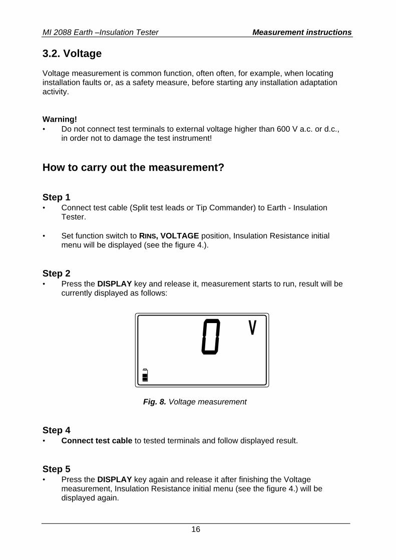
menu will be displayed (see the figure 4.). Step 2 • Press the DISPLAY key and release it, measurement starts to run, result will be
currently displayed as follows:
Fig. 8. Voltage measurement
Step 4 • Connect test cable to tested terminals and follow displayed result. Step 5 • Press the DISPLAY key again and release it after finishing the Voltage
measurement, Insulation Resistance initial menu (see the figure 4.) will be displayed again.
MI 2088 Earth –Insulation Tester Measurement instructions
17
Instead of pressing DISPLAY key, it is also possible to start Insulation Resistance measurement directly, pressing the START key. • Store displayed result for documentation purpose, see instructions how to store
it in chapter 4.1. Storing of test results. Notes! • AC (effective value) or DC voltage, up to 600V can be measured. Polarity, in
case of DC voltage, will not be displayed! • If measured voltage is higher than 600V, >600V message will be displayed! • bat message, displayed during or after finishing the measurement, means,
batteries are too weak to guarantee correct result. Replace the batteries.
MI 2088 Earth –Insulation Tester Measurement instructions
18
3.3. Continuity of Protection Conductors Continuity of protection conductors is to be measured, before mains voltage is connected to tested installation (new or adapted installations). Max. allowed resistance value depends on the power of connected loads, used installation system (TN, TT) etc. For additional general information concerning Continuity measurement, refer to enclosed handbook Measurements on electric installations in practice and theory. Warning! • Make sure tested object to be deenergized (mains voltage disconnected) before
starting the measurement! How to carry out the measurement ? Step 1 • Connect test cable (Split test leads or Tip Commander) to Earth - Insulation
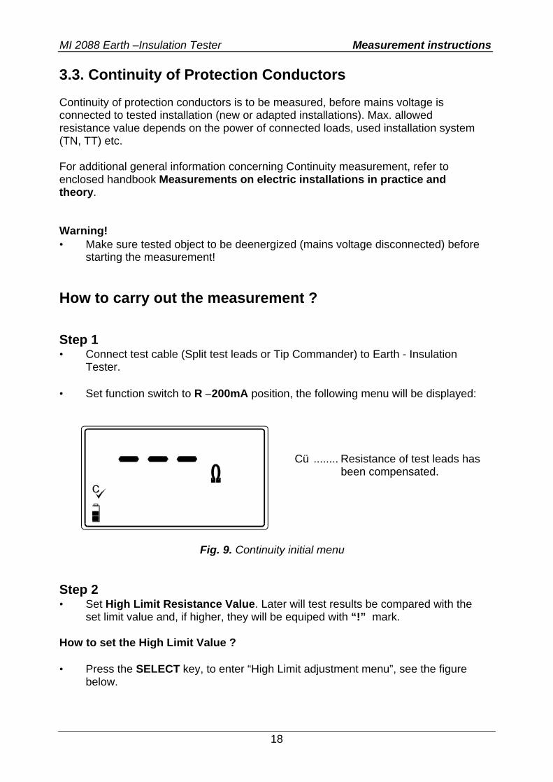
Tester. • Set function switch to R ±200mA position, the following menu will be displayed:
Fig. 9. Continuity initial menu
Step 2 • Set High Limit Resistance Value. Later will test results be compared with the
set limit value and, if higher, they will be equiped with “!” mark. How to set the High Limit Value ? • Press the SELECT key, to enter “High Limit adjustment menu”, see the figure
below.
Cü ........ Resistance of test leads has been compensated.
MI 2088 Earth –Insulation Tester Measurement instructions
19
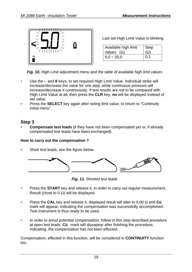
Fig. 10. High Limit adjustment menu and the table of available high limit values
• Use the ↑ and ↓ keys, to set required High Limit Value. Individual strike will
increase/decrease the value for one step, while continuous pressure will increase/decrease it continuously. If test results are not to be compared with High Limit Value at all, then press the CLR key, no will be displayed instead of set value.
• Press the SELECT key again after seting limit value, to return to “Continuity initial menu”.
Step 3 • Compensate test leads (if they have not been compensated yet or, if already
compensated test leads have been exchanged). How to carry out the compensation ? • Short test leads, see the figure below.
Fig. 11. Shorted test leads
• Press the START key and release it, in order to carry out regular measurement.
Result (close to 0 Ω) will be displayed. • Press the CAL key and release it, displayed result will alter to 0,00 Ω and Cü
mark will appear, indicating the compensation was successfully accomplished. Test instrument is thus ready to be used.
• In order to annul potential compensation, follow in this step described procedure
at open test leads. Cü mark will dissapear after finishing the procedure, indicating, the compensation has not been effected.
Compensation, effected in this function, will be considered in CONTINUITY function too.
Last set High Limit Value is blinking.
Available high limit values (Ω)
Step (Ω)
0,0 ÷ 20,0 0,1
MI 2088 Earth –Insulation Tester Measurement instructions
20
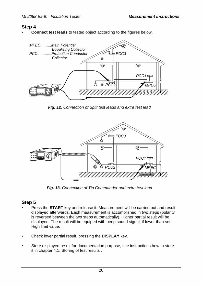
Step 4 • Connect test leads to tested object according to the figures below.
Fig. 12. Connection of Split test leads and extra test lead
Fig. 13. Connection of Tip Commander and extra test lead
Step 5 • Press the START key and release it. Measurement will be carried out and result
displayed afterwards. Each measurement is accomplished in two steps (polarity is reversed between the two steps automatically). Higher partial result will be displayed. The result will be equiped with beep sound signal, if lower than set High limit value.
• Check lover partial result, pressing the DISPLAY key. • Store displayed result for documentation purpose, see instructions how to store
it in chapter 4.1. Storing of test results .
MI 2088 Earth –Insulation Tester Measurement instructions
21
Notes! • In case of present external voltage higher than 9 V a.c./d.c. between test
terminals, the Continuity measurement will not be carried out after pressing START key, but the voltage will be displayed, equiped with “!” mark! Beep warning sound will be effected too.
• If resistance value higher than 5 Ω (measured with not-compensated instrument)
is displayed, compensation will not be carried out after pressing CAL key, even more, already effected compensation will be annuled (Cü mark will disappear)!
• If test result is out of measurement range (open test leads), >1999 Ω message
will be displayed! • bat message, displayed during or after finishing the measurement, means,
batteries are too weak to guarantee correct result. Replace the batteries.
MI 2088 Earth –Insulation Tester Measurement instructions
22
3.4. Continuity The function is intended to be used especially when arranging terminal to terminal connections, mentaining and reparing electric equipment, carrying out auxiliary measurements etc. The function operates continuously and serves as ordinary Ω-meter with low test current. For additional general information concerning Continuity measurement, refer to enclosed handbook Measurements on electric installations in practice and theory. Warning! • If test tips are connected to mains voltage during the measurement is running,
fuse M 0,315 A / 250 V (mounted in vertikal plastic cilinder under battery cover) will blow (see the chapter 5.2. Fuses ).
How to carry out the measurement ? Step 1 • Connect test cable (Split test leads or Tip Commander) to Earth - Insulation
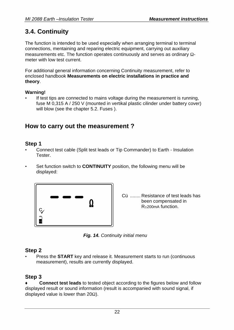
Tester. • Set function switch to CONTINUITY position, the following menu will be
displayed:
Fig. 14. Continuity initial menu
Step 2 • Press the START key and release it. Measurement starts to run (continuous
measurement), results are currently displayed. Step 3 ♦ Connect test leads to tested object according to the figures below and follow displayed result or sound information (result is accompanied with sound signal, if displayed value is lower than 20Ω).
Cü ........ Resistance of test leads has been compensated in R±200mA function.
MI 2088 Earth –Insulation Tester Measurement instructions
23
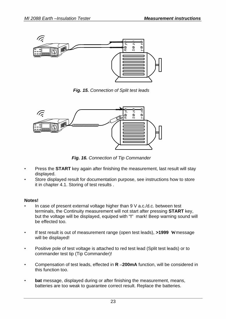
Fig. 15. Connection of Split test leads
Fig. 16. Connection of Tip Commander
• Press the START key again after finishing the measurement, last result will stay
displayed. • Store displayed result for documentation purpose, see instructions how to store
it in chapter 4.1. Storing of test results . Notes! • In case of present external voltage higher than 9 V a.c./d.c. between test
terminals, the Continuity measurement will not start after pressing START key, but the voltage will be displayed, equiped with “!” mark! Beep warning sound will be effected too.
• If test result is out of measurement range (open test leads), >1999 Ω message
will be displayed! • Positive pole of test voltage is attached to red test lead (Split test leads) or to
commander test tip (Tip Commander)! • Compensation of test leads, effected in R ±200mA function, will be considered in
this function too. • bat message, displayed during or after finishing the measurement, means,
batteries are too weak to guarantee correct result. Replace the batteries.
MI 2088 Earth –Insulation Tester Measurement instructions
24
3.5. Earth Resistance (internal generator) The Earth - Insulation Tester is able to carry out Earth Resistance measurement using three different methods. The appropriate one is to be selected by the operater on basis of concrete earthing system to be tested. Main advantages of Internal-generator system against external (mains)- test voltage one are: • Test instrument operates autonomously (regardless of present or not present
mains voltage). • Partial Earth Resistances can be measured, using test clamp (without
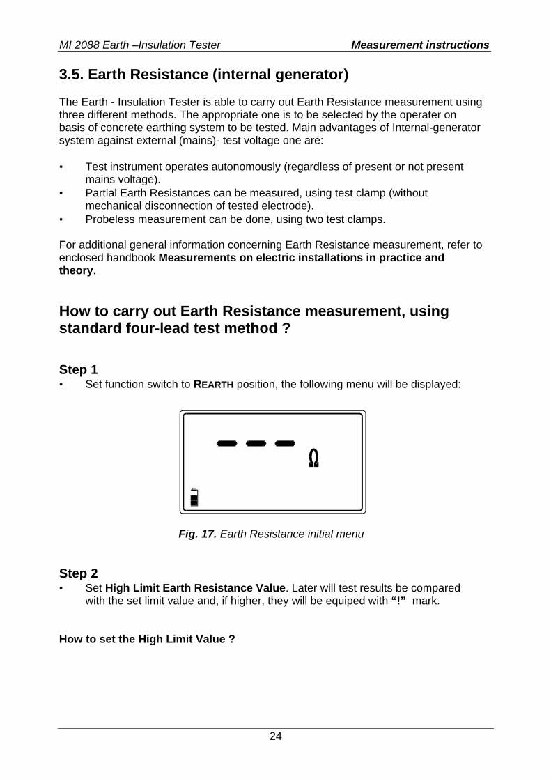
mechanical disconnection of tested electrode). • Probeless measurement can be done, using two test clamps. For additional general information concerning Earth Resistance measurement, refer to enclosed handbook Measurements on electric installations in practice and theory. How to carry out Earth Resistance measurement, using standard four-lead test method ? Step 1 • Set function switch to REARTH position, the following menu will be displayed:
Fig. 17. Earth Resistance initial menu
Step 2 • Set High Limit Earth Resistance Value. Later will test results be compared
with the set limit value and, if higher, they will be equiped with “!” mark.
How to set the High Limit Value ?
MI 2088 Earth –Insulation Tester Measurement instructions
25
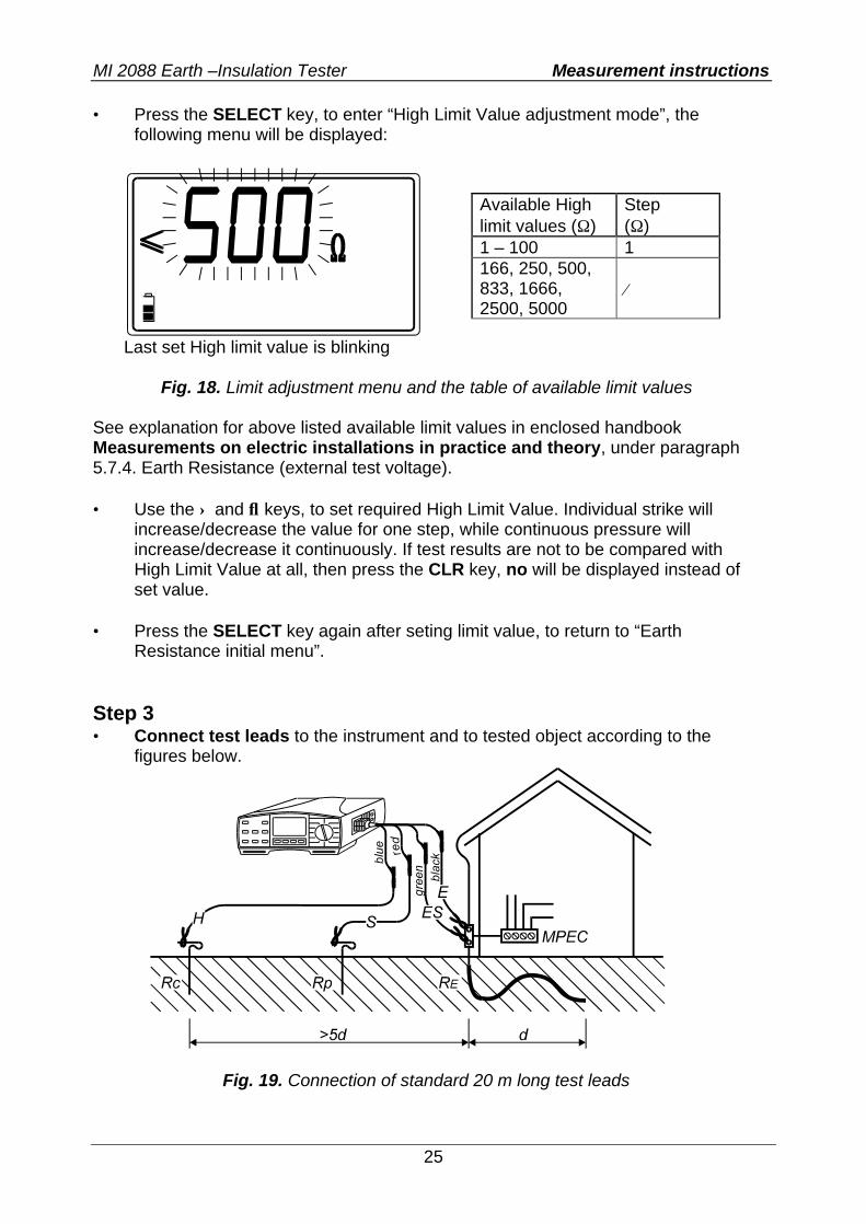
• Press the SELECT key, to enter “High Limit Value adjustment mode”, the following menu will be displayed:
Last set High limit value is blinking
Fig. 18. Limit adjustment menu and the table of available limit values See explanation for above listed available limit values in enclosed handbook Measurements on electric installations in practice and theory, under paragraph 5.7.4. Earth Resistance (external test voltage). • Use the ↑ and ↓ keys, to set required High Limit Value. Individual strike will
increase/decrease the value for one step, while continuous pressure will increase/decrease it continuously. If test results are not to be compared with High Limit Value at all, then press the CLR key, no will be displayed instead of set value.
• Press the SELECT key again after seting limit value, to return to “Earth
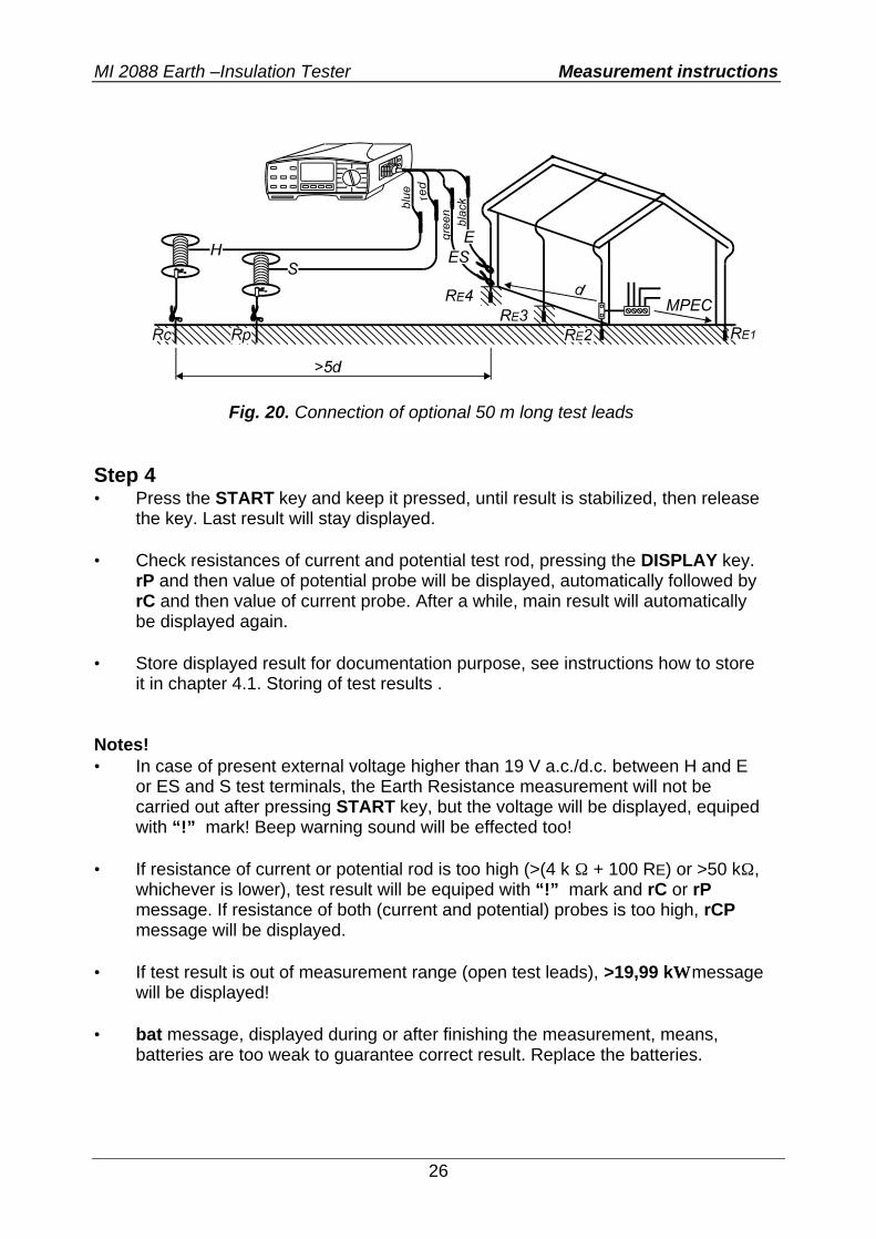
Resistance initial menu”. Step 3 • Connect test leads to the instrument and to tested object according to the
figures below.
Fig. 19. Connection of standard 20 m long test leads
Available High limit values (Ω)
Step (Ω)
1 – 100 1 166, 250, 500, 833, 1666, 2500, 5000
⁄
MI 2088 Earth –Insulation Tester Measurement instructions
26
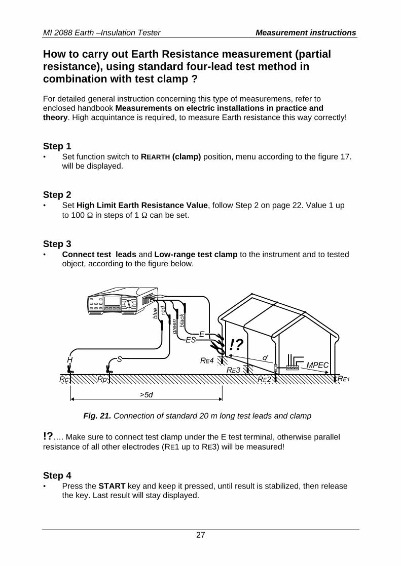
Fig. 20. Connection of optional 50 m long test leads
Step 4 • Press the START key and keep it pressed, until result is stabilized, then release
the key. Last result will stay displayed. • Check resistances of current and potential test rod, pressing the DISPLAY key.
rP and then value of potential probe will be displayed, automatically followed by rC and then value of current probe. After a while, main result will automatically be displayed again.
• Store displayed result for documentation purpose, see instructions how to store
it in chapter 4.1. Storing of test results . Notes! • In case of present external voltage higher than 19 V a.c./d.c. between H and E
or ES and S test terminals, the Earth Resistance measurement will not be carried out after pressing START key, but the voltage will be displayed, equiped with “!” mark! Beep warning sound will be effected too!
• If resistance of current or potential rod is too high (>(4 k Ω + 100 RE) or >50 kΩ,
whichever is lower), test result will be equiped with “!” mark and rC or rP message. If resistance of both (current and potential) probes is too high, rCP message will be displayed.
• If test result is out of measurement range (open test leads), >19,99 kΩ message
will be displayed! • bat message, displayed during or after finishing the measurement, means,
batteries are too weak to guarantee correct result. Replace the batteries.
MI 2088 Earth –Insulation Tester Measurement instructions
27
How to carry out Earth Resistance measurement (partial resistance), using standard four-lead test method in combination with test clamp ? For detailed general instruction concerning this type of measuremens, refer to enclosed handbook Measurements on electric installations in practice and theory. High acquintance is required, to measure Earth resistance this way correctly! Step 1 • Set function switch to REARTH (clamp) position, menu according to the figure 17.
will be displayed. Step 2 • Set High Limit Earth Resistance Value, follow Step 2 on page 22. Value 1 up
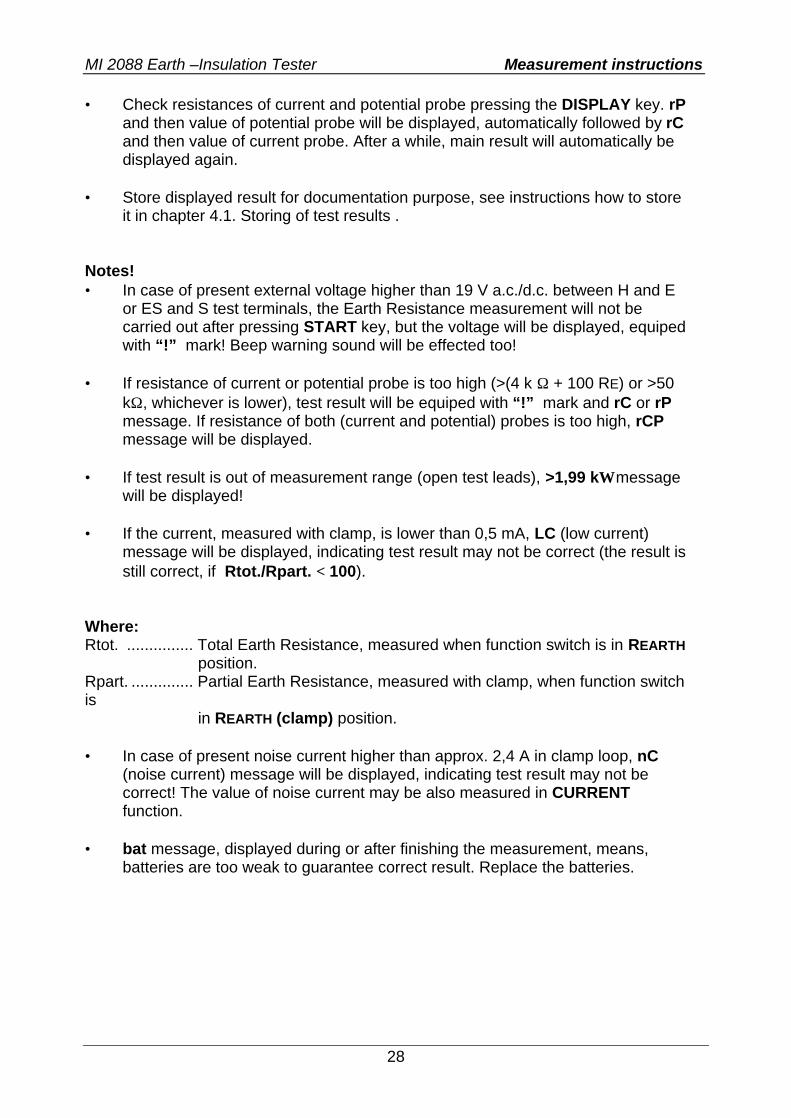
to 100 Ω in steps of 1 Ω can be set. Step 3 • Connect test leads and Low-range test clamp to the instrument and to tested
object, according to the figure below.
Fig. 21. Connection of standard 20 m long test leads and clamp
!?…. Make sure to connect test clamp under the E test terminal, otherwise parallel resistance of all other electrodes (RE1 up to RE3) will be measured! Step 4 • Press the START key and keep it pressed, until result is stabilized, then release
the key. Last result will stay displayed.
MI 2088 Earth –Insulation Tester Measurement instructions
28
• Check resistances of current and potential probe pressing the DISPLAY key. rP and then value of potential probe will be displayed, automatically followed by rC and then value of current probe. After a while, main result will automatically be displayed again.
• Store displayed result for documentation purpose, see instructions how to store
it in chapter 4.1. Storing of test results . Notes! • In case of present external voltage higher than 19 V a.c./d.c. between H and E
or ES and S test terminals, the Earth Resistance measurement will not be carried out after pressing START key, but the voltage will be displayed, equiped with “!” mark! Beep warning sound will be effected too!
• If resistance of current or potential probe is too high (>(4 k Ω + 100 RE) or >50
kΩ, whichever is lower), test result will be equiped with “!” mark and rC or rP message. If resistance of both (current and potential) probes is too high, rCP message will be displayed.
• If test result is out of measurement range (open test leads), >1,99 kΩ message
will be displayed! • If the current, measured with clamp, is lower than 0,5 mA, LC (low current)
message will be displayed, indicating test result may not be correct (the result is still correct, if Rtot./Rpart. < 100).
Where: Rtot. ............... Total Earth Resistance, measured when function switch is in REARTH position. Rpart. .............. Partial Earth Resistance, measured with clamp, when function switch is in REARTH (clamp) position. • In case of present noise current higher than approx. 2,4 A in clamp loop, nC
(noise current) message will be displayed, indicating test result may not be correct! The value of noise current may be also measured in CURRENT function.
• bat message, displayed during or after finishing the measurement, means,
batteries are too weak to guarantee correct result. Replace the batteries.
MI 2088 Earth –Insulation Tester Measurement instructions
29
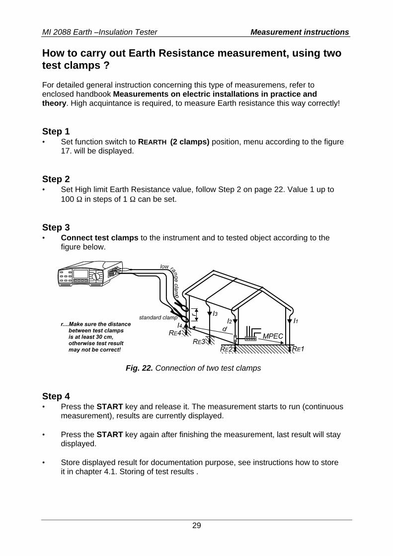
How to carry out Earth Resistance measurement, using two test clamps ? For detailed general instruction concerning this type of measuremens, refer to enclosed handbook Measurements on electric installations in practice and theory. High acquintance is required, to measure Earth resistance this way correctly! Step 1 • Set function switch to REARTH (2 clamps) position, menu according to the figure
17. will be displayed. Step 2 • Set High limit Earth Resistance value, follow Step 2 on page 22. Value 1 up to
100 Ω in steps of 1 Ω can be set. Step 3 • Connect test clamps to the instrument and to tested object according to the
figure below.
Fig. 22. Connection of two test clamps
Step 4 • Press the START key and release it. The measurement starts to run (continuous
measurement), results are currently displayed. • Press the START key again after finishing the measurement, last result will stay
displayed. • Store displayed result for documentation purpose, see instructions how to store
it in chapter 4.1. Storing of test results .
MI 2088 Earth –Insulation Tester Measurement instructions
30
Notes! • In case of present external voltage higher than 19 V a.c./d.c. between H and E
or ES and S test terminals, the Earth Resistance measurement will not be carried out after pressing START key, but the voltage will be displayed, equiped with “!” mark! Beep warning sound will be effected too!
• In case of the ratio Noise current / Measurement current > 100, nC (noise
current) message will be displayed, indicating test result may not be correct! The value of noise current may be also measured in CURRENT function.
• If test result is out of measurement range (open test leads), >99,9 Ω message
will be displayed! • If the current, measured with clamp, is lower than 0,5 mA, LC (low current)
message will be displayed, indicating test result may not be correct! • bat message, displayed during or after finishing the measurement, means,
batteries are too weak to guarantee correct result. Replace the batteries.
MI 2088 Earth –Insulation Tester Measurement instructions
31
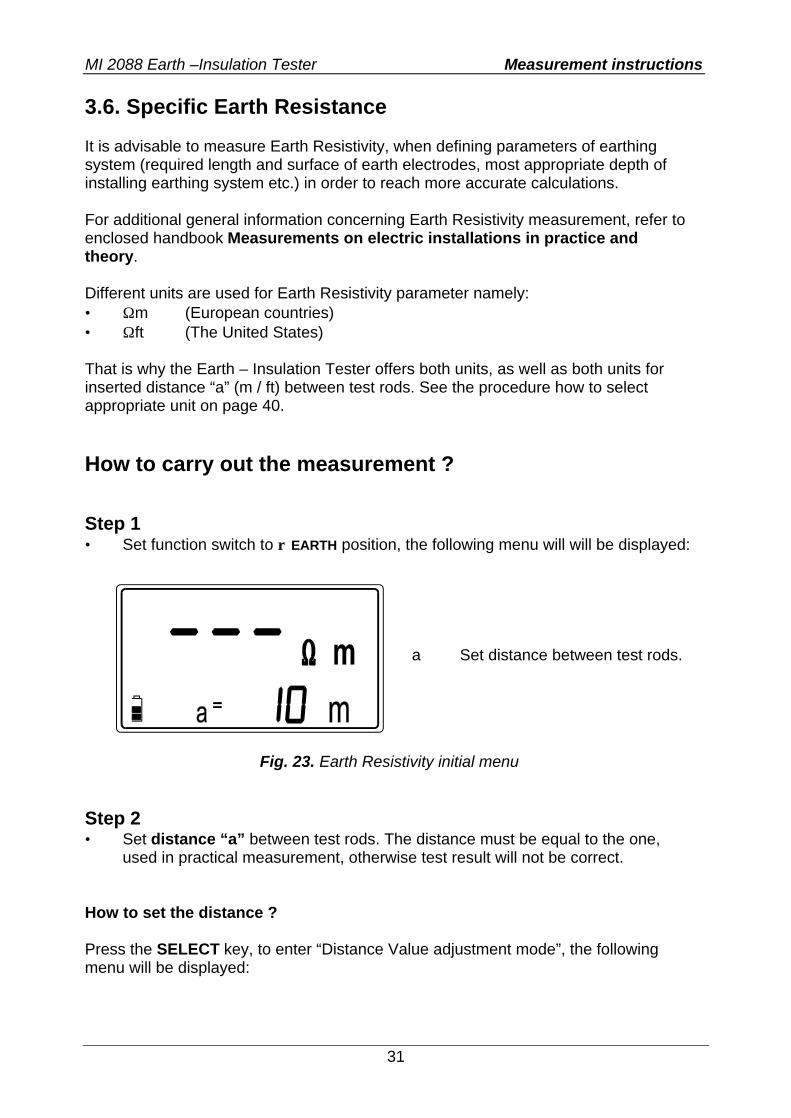
3.6. Specific Earth Resistance It is advisable to measure Earth Resistivity, when defining parameters of earthing system (required length and surface of earth electrodes, most appropriate depth of installing earthing system etc.) in order to reach more accurate calculations. For additional general information concerning Earth Resistivity measurement, refer to enclosed handbook Measurements on electric installations in practice and theory. Different units are used for Earth Resistivity parameter namely: • Ωm (European countries) • Ωft (The United States) That is why the Earth – Insulation Tester offers both units, as well as both units for inserted distance “a” (m / ft) between test rods. See the procedure how to select appropriate unit on page 40. How to carry out the measurement ? Step 1 • Set function switch to ρ EARTH position, the following menu will will be displayed:
Fig. 23. Earth Resistivity initial menu
Step 2 • Set distance “a” between test rods. The distance must be equal to the one,
used in practical measurement, otherwise test result will not be correct. How to set the distance ? Press the SELECT key, to enter “Distance Value adjustment mode”, the following menu will be displayed:
a Set distance between test rods.
MI 2088 Earth –Insulation Tester Measurement instructions
32
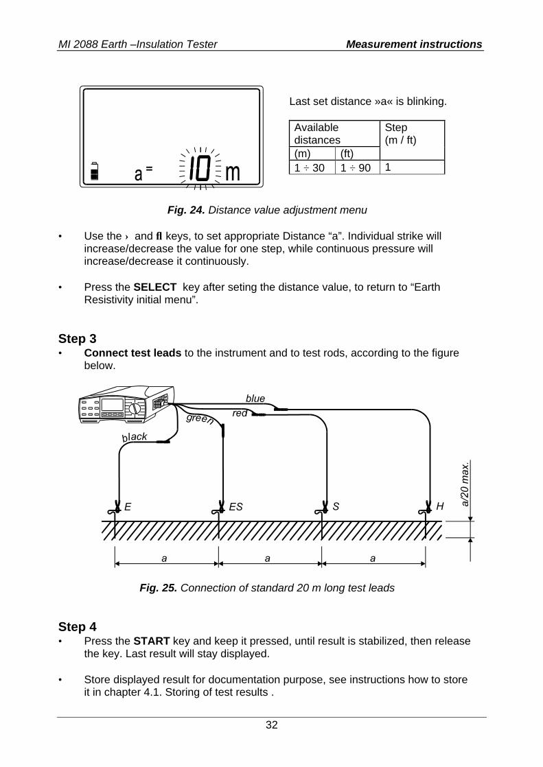
Fig. 24. Distance value adjustment menu
• Use the ↑ and ↓ keys, to set appropriate Distance “a”. Individual strike will
increase/decrease the value for one step, while continuous pressure will increase/decrease it continuously.
• Press the SELECT key after seting the distance value, to return to “Earth
Resistivity initial menu”. Step 3 • Connect test leads to the instrument and to test rods, according to the figure
below.
Fig. 25. Connection of standard 20 m long test leads
Step 4 • Press the START key and keep it pressed, until result is stabilized, then release
the key. Last result will stay displayed. • Store displayed result for documentation purpose, see instructions how to store
it in chapter 4.1. Storing of test results .
Last set distance »a« is blinking. Available distances (m) (ft)
Step (m / ft)
1 ÷ 30 1 ÷ 90 1
MI 2088 Earth –Insulation Tester Measurement instructions
33
Notes! • In case of present external voltage higher than 19 V a.c./d.c. between H and E
or ES and S test terminals, the Earth Resistivity measurement will not be carried out after pressing START key, but the voltage will be displayed, equiped with “!” mark! Beep warning sound will be effected too!
• If resistance of current or potential probe is too high (>(4 k Ω + 100 RE) or >50
kΩ, whichever is lower), test result will be equiped with “!” mark and • rC or rP message. If resistance of both (current and potential) probes is too high,
rCP message will be displayed. • If test result is out of measurement range (for example open test leads), then
>999 kΩm (a < 8m) / >1999 kΩm (a ≥ 8m) or > 999 kΩft (a < 8ft) / >1999 kΩft • (a ≥ 8m) message will be displayed! • bat message, displayed during or after finishing the measurement, means,
batteries are too weak to guarantee correct result. Replace the batteries.

MI 2088 Earth –Insulation Tester Measurement instructions
34
3.7. Current (True RMS) For general information concerning the measurement, refer to enclosed handbook Measurements on electric installations in practice and theory. Warning! • Do not attach any external voltage between C1 and C2(P) test terminals! How to carry out the measurement ? Step 1 • Connect current / current (1000:1) test clamp to Earth - Insulation Tester, see
the figure 27. Be aware that low-range test clamp, supplied by METREL, can cover the range 0,5 mA up to 200 A, while standard-range test clamp can measure within 10 mA and 200 A.
• Set function switch to CURRENT (clamp) position, the following menu will be
displayed:
Fig 26. Current function initial menu
Step 2 • Connect test clamp to tested object, according to the figure below.
Fig. 27. Connection of test clamp
IL Leakage current. I Phase
current.
MI 2088 Earth –Insulation Tester Measurement instructions
35
Step 3 • Press the START key and release it. Measurement starts to run (continuous
measurement), result is currently displayed. • Press the START key again after finishing the current measurement, last result
will stay displayed. • Store displayed result for documentation purpose, see instructions how to store
it in chapter 4.1. Storing of test results . Note! • bat message, displayed during or after finishing the measurement, means,
batteries are too weak to guarantee correct result. Replace the batteries.
MI 2088 Earth –Insulation Tester Measurement instructions
36
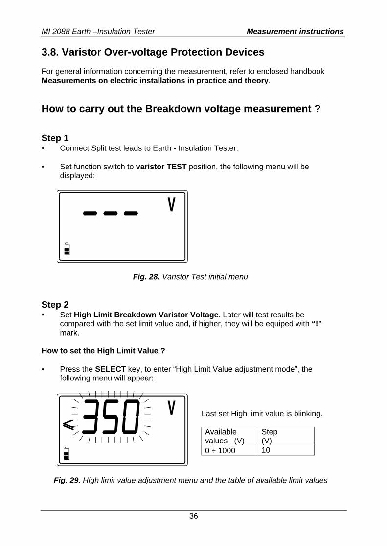
3.8. Varistor Over-voltage Protection Devices For general information concerning the measurement, refer to enclosed handbook Measurements on electric installations in practice and theory. How to carry out the Breakdown voltage measurement ? Step 1 • Connect Split test leads to Earth - Insulation Tester. • Set function switch to varistor TEST position, the following menu will be
displayed:
Fig. 28. Varistor Test initial menu
Step 2 • Set High Limit Breakdown Varistor Voltage. Later will test results be
compared with the set limit value and, if higher, they will be equiped with “!” mark.
How to set the High Limit Value ? • Press the SELECT key, to enter “High Limit Value adjustment mode”, the
following menu will appear:
Fig. 29. High limit value adjustment menu and the table of available limit values
Last set High limit value is blinking. Available values (V)
Step (V)
0 ÷ 1000 10
MI 2088 Earth –Insulation Tester Measurement instructions
37
• Use the ↑ and ↓ keys, to set required High Limit Value. Individual strike will increase/decrease the value for one step, while continuous pressure will increase/decrease it continuously. If test results are not to be compared with High Limit Value at all, then press the CLR key, no will be displayed instead of set value.
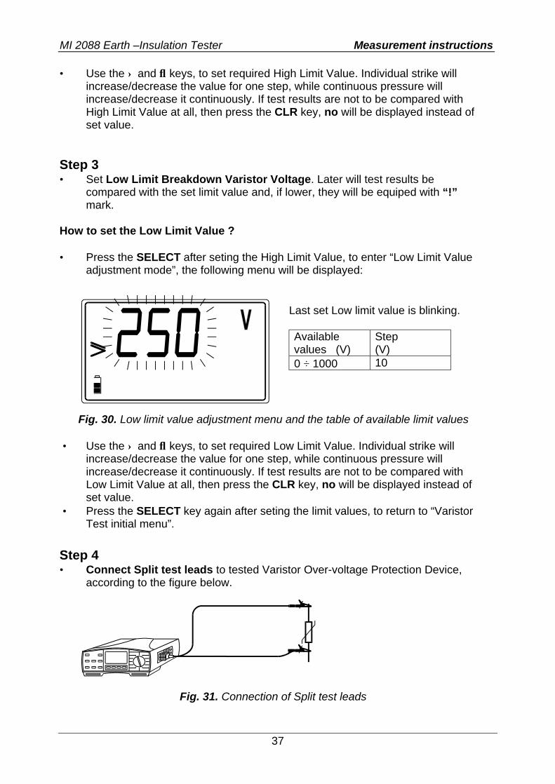
Step 3 • Set Low Limit Breakdown Varistor Voltage. Later will test results be
compared with the set limit value and, if lower, they will be equiped with “!” mark.
How to set the Low Limit Value ? • Press the SELECT after seting the High Limit Value, to enter “Low Limit Value
adjustment mode”, the following menu will be displayed:
Fig. 30. Low limit value adjustment menu and the table of available limit values
• Use the ↑ and ↓ keys, to set required Low Limit Value. Individual strike will
increase/decrease the value for one step, while continuous pressure will increase/decrease it continuously. If test results are not to be compared with Low Limit Value at all, then press the CLR key, no will be displayed instead of set value.
• Press the SELECT key again after seting the limit values, to return to “Varistor Test initial menu”.
Step 4 • Connect Split test leads to tested Varistor Over-voltage Protection Device,
according to the figure below.
Fig. 31. Connection of Split test leads
Last set Low limit value is blinking. Available values (V)
Step (V)
0 ÷ 1000 10
MI 2088 Earth –Insulation Tester Measurement instructions
38
Step 5 • Press the START key and release it. Test voltage starts to rise (500 V/s) and as
soon as varistor’s forward current reaches the value of 1 mA (Breakdown Voltage is defined at that current), the voltage will be displayed. Generator will stop to generate test voltage.
• Check the Breakdown voltage scaled to a.c. value called Uac presing the
DISPLAY key. Uac = Ubreakdown (main result) / 1,6 Meaning of the Uac voltage: Protection devices intended for a.c. network are usually dimensioned approx. 20% of nominal mains voltage above peak value of nominal mains voltage. Example: Nominal mains voltage Un = 230V Upeak = 230V⋅1,41 = 324V Ubreakdown = (Upeak + 0,2⋅Un) ≅ Un⋅1,6 = 368V Uac voltage may be directly compared with the voltage declared on tested protection device. • Store displayed result for documentation purpose, see instructions how to store
it in chapter 4.1. Storing of test results . Notes! • In order test result not to be influenced by connected loads, tested Over-voltage
Device must be removed from installation, before testing it. • If the Over-voltage Protection Device to be tested, is not possible to be removed
from installation (permanent connection), make sure to disconnect all other elements connected to installation, which may influence on test result.
• bat message, displayed during or after finishing the measurement, means,
batteries are too weak to guarantee correct result. Replace the batteries.
MI 2088 Earth –Insulation Tester Memory and other operations
39
4. Memory and other operations 4.1. Storing of test results All test results can be stored, for later documentation purpose except Voltage and CONTINUITY measurements (auxiliary functions). How to store displayed test result? Once test result is displayed, the following procedure is to be realized:
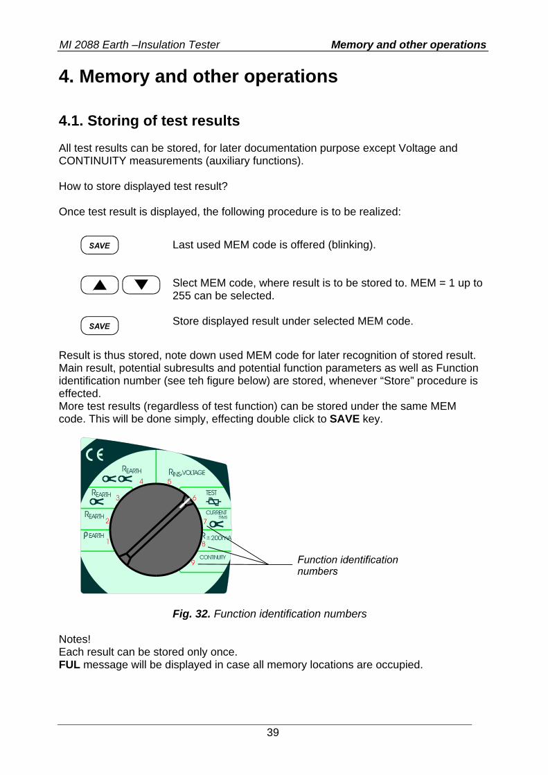
Result is thus stored, note down used MEM code for later recognition of stored result. Main result, potential subresults and potential function parameters as well as Function identification number (see teh figure below) are stored, whenever “Store” procedure is effected. More test results (regardless of test function) can be stored under the same MEM code. This will be done simply, effecting double click to SAVE key.
Fig. 32. Function identification numbers
Notes! Each result can be stored only once. FUL message will be displayed in case all memory locations are occupied.
Last used MEM code is offered (blinking). Slect MEM code, where result is to be stored to. MEM = 1 up to 255 can be selected. Store displayed result under selected MEM code.
MI 2088 Earth –Insulation Tester Memory and other operations
40
4.2. Recalling of stored results Stored results can be displayed whenever needed for visual check. Main result, potential subresult and potential function parameter can be recalled. How to recall stored results?
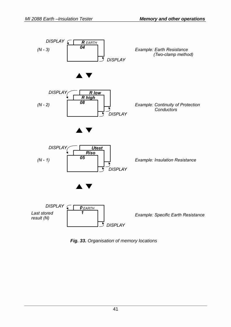
If there is no stored result at all, no message will be displayed for a while, after pressing RCL key. If there is no stored result under set MEM code, no message will be displayed for a while whenever the code is changed. Organisation of memory locations, under a certain MEM code, is presented on the figure below.
MEM code will be offered (blinking). Function identification number of last result, stored under offered MEM code, will be displayed. Set MEM code, Function identification number will follow set MEM code currently. MEM code will stop blinking. Check main result, subresult and function parameter, hidden behind displayed Function identification number. Move to other test results, stored under the same MEM code. Function identification number must be displayed (set by DISPLAY key), before using the ↑ and ↓ keys. Check main result, subresult and function parameter, hidden behind displayed Function identification number. MEM code starts blinking again, repeat the whole procedure, to recall results, stored under other MEM codes.
MI 2088 Earth –Insulation Tester Memory and other operations
41
Fig. 33. Organisation of memory locations
MI 2088 Earth –Insulation Tester Memory and other operations
42
4.3. Erasing of stored results Two modes of erasing stored results are available namely: All stored results can be erased in one step A certain stored result only, can be erased How to erase all stored results? Press the CLR key, Clr ALL MEM message starts to blink. Confirm erasing, pressing the CLR key again, all stored results will be erased. How to erase only a certain stored result? Recall a certain result to be erased, following the procedure described in paragraph 4.2. Recalling of stored results.
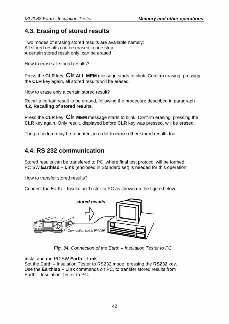
Press the CLR key, Clr MEM message starts to blink. Confirm erasing, pressing the CLR key again. Only result, displayed before CLR key was pressed, will be erased. The procedure may be repeated, in order to erase other stored results too. 4.4. RS 232 communication Stored results can be transfered to PC, where final test protocol will be formed. PC SW EarthIso – Link (enclosed in Standard set) is needed for this operation. How to transfer stored results? Connect the Earth – Insulation Tester to PC as shown on the figure below.
Fig. 34. Connection of the Earth – Insulation Tester to PC
Instal and run PC SW Earth – Link. Set the Earth – Insulation Tester to RS232 mode, pressing the RS232 key. Use the EarthIso – Link commands on PC, to transfer stored results from Earth – Insulation Tester to PC.
MI 2088 Earth –Insulation Tester Memory and other operations
43
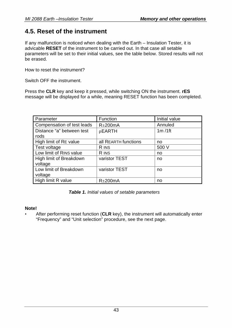
4.5. Reset of the instrument If any malfunction is noticed when dealing with the Earth – Insulation Tester, it is advicable RESET of the instrument to be carried out. In that case all setable parameters will be set to their initial values, see the table below. Stored results will not be erased. How to reset the instrument? Switch OFF the instrument. Press the CLR key and keep it pressed, while switching ON the instrument. rES message will be displayed for a while, meaning RESET function has been completed.
Parameter Function Initial value Compensation of test leads R±200mA Annuled Distance “a” between test rods
ρEARTH 1m /1ft
High limit of RE value all REARTH functions no Test voltage R INS 500 V Low limit of RINS value R INS no High limit of Breakdown voltage
varistor TEST no
Low limit of Breakdown voltage
varistor TEST no
High limit R value R±200mA no
Table 1. Initial values of setable parameters Note! • After performing reset function (CLR key), the instrument will automatically enter
“Frequency” and “Unit selection” procedure, see the next page.
MI 2088 Earth –Insulation Tester Memory and other operations
44
4.6. General setings Usually, there are noise voltages/currents present on measured objects, caused by mains voltage somewhere in near or far neighbourhood. Mains voltage frequency is different in different countries (50 Hz in European countries etc., 60 Hz in the United States etc.). In order, test results to be stabile and correct, regardless of present noise, it is necessary to insert nominal frequency of mains system. On basis of set frequency will the Earth – Insulation Tester automatically adjust integrating timing, in order to reach high immunity against mains noise. The frequency once set, will stay set, even after replacing batteries. How to insert the frequency of mains voltage (50/60 Hz) and the unit of Specific Earth Resistance parameter (Ωm/Ωft)? • Switch OFF the instrument. • Press the SELECT key and keep it pressed while switching ON the instrument,
until 50 or 60 value (last selected) starts to blink. Select appropriate frequency of mains voltage using the ↑ or ↓ key.
• Press the SELECT key, unit m or ft (last selected), used in Earth Resistivity
measurement, starts to blink. Select appropriate unit using the ↑ or ↓ key. • Press the SELECT key again, to abandom “Frequency” and “Unit selection
menu”, the instrument is ready for regular measurements. New selection is also offered after each reseting of the instrument, see the procedure in chapter 4.5.Reset of the instrument!
MI 2088 Earth –Insulation Tester Maintenance
45
5. Maintenance 5.1. Batteries
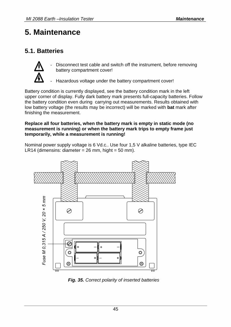
Battery condition is currently displayed, see the battery condition mark in the left upper corner of display. Fully dark battery mark presents full-capacity batteries. Follow the battery condition even during carrying out measurements. Results obtained with low battery voltage (the results may be incorrect) will be marked with bat mark after finishing the measurement. Replace all four batteries, when the battery mark is empty in static mode (no measurement is running) or when the battery mark trips to empty frame just temporarily, while a measurement is running! Nominal power supply voltage is 6 Vd.c.. Use four 1,5 V alkaline batteries, type IEC LR14 (dimensins: diameter = 26 mm, hight = 50 mm).
Fig. 35. Correct polarity of inserted batteries
- Disconnect test cable and switch off the instrument, before removing battery compartment cover!
- Hazardous voltage under the battery compartment cover!
MI 2088 Earth –Insulation Tester Maintenance
46
One set of full-capacity batteries can supply the instrument approx. 50 hours at the ratio measurement / pause = 5s / 25s. Notes! • Insert batteries correctly, otherwise test instrument will not operate and batteries
may be discharged, see the figure 35. for correct battery polarity. • Transfer stored results to PC, before removing the batteries! • The results will be lost, when the batteries are removed and all setable
parameters will be set to their initial values after replacing the batteries, see the paragraph 4.5. Reset of the instrument!
In order not to loose stored data, follow the next procedure, when replacing the batteries: • Switch OFF the instrument. • Replace the batteries within one minute. • Switch ON the instrument, Clr mem message will not be displayed, indicating
stored data has not been erased. 5.2. Fuses There is one fuse under battery compartment cover (see the figure 35.). It is intended to protect internal circuitry of the test instrument, if test tips are connected to mains voltage by mistake, when function switch in R ±200mA or CONTINUITY position. Fuse type: M 0,315A/250V, 20 × 5 mm Check the fuse if “FUS” message is displayed. Warning! • Replace blown fuse with original one only, otherwise the instrument may be
damaged and/or operater’s safety impaired! 5.3. Cleaning Use soft patch, slightly moistened with soap water or alcohol, to clean the surface of Earth - Insulation Tester and leave the instrument to dry totally before using it. Notes! • Do not use liquids based on petrol or hydrocarbons! • Do not spill cleaning liquid over the instrument!
MI 2088 Earth –Insulation Tester Maintenance
47
5.4. Periodic calibration It is essential, that all measurement instruments are regularly calibrated. For occasional daily use, we recommend an annual calibration to be carried out. When the instrument is used continuously every day, we recommend that calibration is carried out every sixth months. 5.5. Service Repairs under or out of waranty time: Please contact your distributor for further information. Distributor’s address: Producer’s address: METREL d.d. Ljubljanska 77 SI-1354 Horjul Tel.: +386 1 75 58 200 Fax.: +386 1 75 49 226 E-mail: [email protected] http://www.metrel.si Unauthorised person is not allowed to open the Earth - Insulation Tester. There are no user replacable components inside the instrument, except the fuse, refer to paragraph 5.2. Fuses.
MI 2088 Earth –Insulation Tester Technical specification
48
6. Technical specification
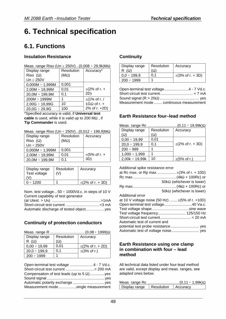
6.1. Functions Insulation Resistance Meas. range Riso (Un ≥ 250V) .. (0,008 ÷ 29,9k)MΩ Display range Riso (Ω) Un ≥ 250V
Resolution (MΩ)
Accuracy*
0,000M ÷ 1,999M 0,001 2,00M ÷ 19,99M 0,01 20,0M ÷ 199,9M 0,1
±(2% of r. + 2D)
200M ÷ 1999M 1 2,00G ÷ 19,99G 10 20,0G ÷ 29,9G 100
±(1% of r. / 1GΩ of r. + 2% of r. +2D)
*Specified accuracy is valid, if Universal test cable is used, while it is valid up to 200 MΩ , if Tip Commander is used. Meas. range Riso (Un < 250V) ..(0,012 ÷ 199,9)MΩ Display range Riso (Ω) Un < 250V
Resolution (MΩ)
Accuracy
0,000M ÷ 1,999M 0,001 2,00M ÷ 19,99M 0,01 20,0M ÷ 199,9M 0,1
±(5% of r. + 3D)
Display range Test voltage (V)
Resolution (V)
Accuracy
0 ÷ 1200 1 ±(2% of r. + 3D) Nom. test voltage...50 ÷ 1000Vd.c. in steps of 10 V Current capability of test generator (at Utest. > UN) ..............................................>1mA Short-circuit test current ................................<3 mA Automatic discharge of tested object..................yes Continuity of protection conductors Meas. range R ................................. (0,08 ÷ 1999)Ω Display range R (Ω)
Resolution (Ω)
Accuracy
0,00 ÷ 19,99 0,01 ±(2% of r. + 2D) 20,0 ÷ 199,9 0,1 200 ÷ 1999 1
±(3% of r.)
Open-terminal test voltage ......................4 - 7 Vd.c. Short-circuit test current ...........................> 200 mA Compensation of test leads (up to 5 Ω)..............yes Sound signal .......................................................yes Automatic polarity exchange ..............................yes Measurement mode.................single measurement
Continuity Display range R (Ω)
Resolution (Ω)
Accuracy
0,0 ÷ 199,9 0,1 200 ÷ 1999 1
±(3% of r. + 3D)
Open-terminal test voltage.......................4 - 7 Vd.c. Short-circuit test current............................... < 7 mA Sound signal (R > 20Ω) ..................................... yes Measurement mode........ continuous measurement Earth Resistance four–lead method Meas. range RE ............................(0,11 ÷ 19,99k)Ω Display range (Ω)
Resolution (Ω)
Accuracy
0,00 ÷ 19,99 0,01 20,0 ÷ 199,9 0,1 200 ÷ 999 1 1,000 ÷ 1,999 1
±(2% of r. + 3D)
2,00k ÷ 19,99k 10 ±(5% of r.) Additional spike resistance error at Rc max. or Rp max. ................. ±(3% of r. + 10D) Rc max......................................... (4kΩ + 100RE) or 50kΩ (whichever is lower) Rp max......................................... (4kΩ + 100RE) or 50kΩ (whichever is lower) Additional error at 10 V voltage noise (50 Hz) ....... ±(5% of r. +10D) Open-terminal test voltage..........................40 Va.c. Test voltage shape...................................sine wave Test voltage frequency.......................... 125/150 Hz Short-circuit test current............................. < 20 mA Automatic test of current and potential test probe resistance........................... yes Automatic test of voltage noise.......................... yes Earth Resistance using one clamp in combination with four – lead method All technical data listed under four-lead method are valid, except display and meas. ranges, see adapted ones below. Meas. range RE .............................. (0,11 ÷ 1,99k)Ω Display range Resolution Accuracy
MI 2088 Earth –Insulation Tester Technical specification
49
(Ω) (Ω) 0,00 ÷ 19,99 0,01 20,0 ÷ 199,9 0,1 200 ÷ 999 1 1,00k ÷ 1,99k 10
±(2% of r. + 3D)
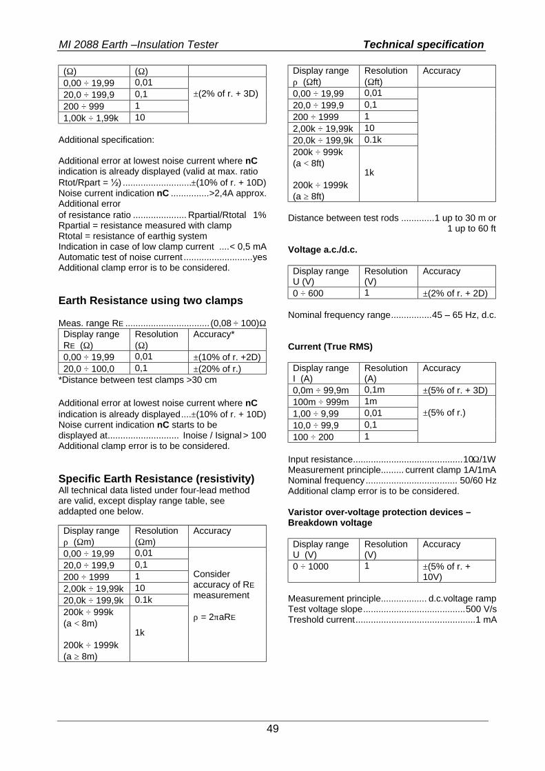
Additional specification: Additional error at lowest noise current where nC indication is already displayed (valid at max. ratio Rtot/Rpart = ½) ...........................±(10% of r. + 10D) Noise current indication nC ...............>2,4A approx. Additional error of resistance ratio ..................... Rpartial/Rtotal ⋅ 1% Rpartial = resistance measured with clamp Rtotal = resistance of earthig system Indication in case of low clamp current ....< 0,5 mA Automatic test of noise current ...........................yes Additional clamp error is to be considered. Earth Resistance using two clamps Meas. range RE ................................. (0,08 ÷ 100)Ω Display range RE (Ω)
Resolution (Ω)
Accuracy*
0,00 ÷ 19,99 0,01 ±(10% of r. +2D) 20,0 ÷ 100,0 0,1 ±(20% of r.)
*Distance between test clamps >30 cm Additional error at lowest noise current where nC indication is already displayed....±(10% of r. + 10D) Noise current indication nC starts to be displayed at............................ Inoise / Isignal > 100 Additional clamp error is to be considered. Specific Earth Resistance (resistivity) All technical data listed under four-lead method are valid, except display range table, see addapted one below. Display range ρ (Ωm)
Resolution (Ωm)
Accuracy
0,00 ÷ 19,99 0,01 20,0 ÷ 199,9 0,1 200 ÷ 1999 1 2,00k ÷ 19,99k 10 20,0k ÷ 199,9k 0.1k 200k ÷ 999k (a < 8m) 200k ÷ 1999k (a ≥ 8m)
1k
Consider accuracy of RE measurement ρ = 2πaRE
Display range ρ (Ωft)
Resolution (Ωft)
Accuracy
0,00 ÷ 19,99 0,01 20,0 ÷ 199,9 0,1 200 ÷ 1999 1 2,00k ÷ 19,99k 10 20,0k ÷ 199,9k 0.1k 200k ÷ 999k (a < 8ft) 200k ÷ 1999k (a ≥ 8ft)
1k
Distance between test rods .............1 up to 30 m or 1 up to 60 ft Voltage a.c./d.c. Display range U (V)
Resolution (V)
Accuracy
0 ÷ 600 1 ±(2% of r. + 2D) Nominal frequency range................45 – 65 Hz, d.c. Current (True RMS) Display range I (A)
Resolution (A)
Accuracy
0,0m ÷ 99,9m 0,1m ±(5% of r. + 3D) 100m ÷ 999m 1m 1,00 ÷ 9,99 0,01 10,0 ÷ 99,9 0,1 100 ÷ 200 1
±(5% of r.)
Input resistance...........................................10Ω/1W Measurement principle......... current clamp 1A/1mA Nominal frequency.................................... 50/60 Hz Additional clamp error is to be considered. Varistor over-voltage protection devices – Breakdown voltage Display range U (V)
Resolution (V)
Accuracy
0 ÷ 1000 1 ±(5% of r. + 10V)
Measurement principle.................. d.c.voltage ramp Test voltage slope........................................500 V/s Treshold current...............................................1 mA
MI 2088 Earth –Insulation Tester Technical specification
50
6.2. General characteristics Power supply .. 6 Vd.c. (4 × 1,5V battery IEC LR14) Automatic comparation of test result with set high and low limit value ......................................yes Vizual and sound warnings.................................yes Dimensions (w × h × d)............ 26,5 × 11 × 18,5 cm Weight (without accessories, with batteries) .. 1,7kg Display ...................................... LCD with backlight Memories ........................ over 1000 measurements Computer connection .................................. RS 232
Protection classification ................double insulation Over-voltage chateg. .. CATIII/300V or CATII/600 V Polution degree...................................................... 2 Degree of protection ........................................IP 44 Working temp. range.................................0 ÷ 40 °C Nominal (reference) temp. range............10 ÷ 30 °C Max. humidity ..........................85 % RH (0 ÷ 40°C) Nominal (reference) hum. range....... 40 ÷ 60 % RH Auto power off.................................................... yes

