early detection of wheel flats using wagon body
DESCRIPTION
EARLY DETECTION OF WHEEL FLATS USING WAGON BODY Acceleration MeasurementsTRANSCRIPT
Conference On Railway Engineering Wellington, Sept 12-15, 2010
EARLY DETECTION OF WHEEL FLATS USING WAGON BODY ACCELERATION MEASUREMENTS
Yan Sun*, Colin Cole**, and Chris Bosomworth***
*PhD, **PhD & Prof., NPER-3, RPEQ, *** Engineer, Centre for Railway Engineering, CQ University
North Rockhampton, QLD 4702, Australia
SUMMARY
A wagon train health system, based on the acceleration measurements on a wagon car body, has been designed to monitor the wagon safety performance indexes – derailment ratio, car body or bogie hunting, speed, maximum dynamic wheel load and wheel unloading due to long-wavelength track geometry irregularities. In this paper, the possibility to monitor the wheel impacts due to short-wavelength defects such as wheel flats using such a system is theoretically presented through the simulations using a comprehensive non-linear vehicle-track interaction dynamics model. The method is restricted to traditional three piece bogie rollingstock. A coal wagon is modeled and a section of track with the geometry irregularity class 5 is selected for the simulations. The simulation results show that the original acceleration measurements on the wagon car body include very high frequency components contributed by the friction elements in the wagon components, which hide the useful messages coming from the wheel impact. A filter has been designed to extract these useful messages. The processed data shows that the wheel impact patterns, even those caused by the smaller wheel flats, can be detected. As expected, wheel impact detection using this approach is limited at lower speeds.
1. INTRODUCTION
Wheel impacts due to wheel flats are particularly pernicious since they input high loads to the track and wheel with each revolution they make, leading to very high frequency dynamic loads. These loads can cause serious damage to vehicle and track components. A wheel flat can be thought of as a short flat spot or loss of roundness on the wheel tread surface, formed on a braked wheelset by abrasion as it slides along the rail.
The vast majority of wheel flats increase in severity over time until they reach the alarm limit. At that point much more material must be removed from the wheel to salvage it than if it had been attended to earlier. This shortens the overall life of the wheel and places a wheel that has been subjected to extreme stress back into operation. It was pointed out [1] that martensite was found beneath all flats and cracks observed in most cases. So, the risk for future spalling should be considered for all wheelsets with flats. A damaged wheelset should be taken out of service as quickly as possible. When re-profiling the wheels, all martensite and an additional layer of several millimetres should be machined off. In addition, wheelsets adjacent to those with severe flats have a high probability of developing defects. It is not uncommon for an adjacent wheelset to show minor impacts just before the condemned one beside it is serviced.
The early detection of wheel flats has become of increased importance to freight and mass transit operators because of economic pressures to raise productivity, usually through longer or more
frequent trains with higher speed and higher axle loads. As a result, the increased likelihood of serious damage to rails, track structure and rolling stock is of major concern to the operator for maintenance and safety reasons. In addition, the increased use of concrete sleepers has resulted in track structures having a much lower compliance, or higher stiffness. This, in turn, exacerbates the effects of impact loading on rails, sleepers and fasteners.
Various approaches to prevention, detection and management have been developed. Control technology has been applied to upgrade the control performance of brake systems on railway vehicles to avoid the generation of wheel flats during braking [2, 3]. On other hand, there have been several recent advancements in wayside detector technology [4-7] that promise to provide the improvement in the early detection of wheel flats. One of the most significant is the Wheel Impact Load Detector (WILD) [7] that came out of the AAR Vehicle Track Systems Research Program. In such a system, accelerometers and strain gauges were installed in a selected track section. When a train passes through this section, the system triggers and then measures and records the passing wheel loads. It was evident from the results that accelerometers were a superior sensor because they provided better frequency response and linearity than strain gauges.
In our research on the early detection of wheel flats has considered a wagon train health advisory system [8-10] and theoretical simulations. The system monitors wagon performance through the
Yan Sun, Colin Cole and Chris Bosomworth EARLY DETECTION OF WHEEL FLATS USING Centre for Railway Engineering, CQ University WAGON BODY ACCELERATION MEASUREMENTS
Conference On Railway Engineering Wellington, Sept 12-15, 2010
wagon car body acceleration measurements to detect derailment ratio, car body or bogie hunting speed, maximum dynamic wheel load and wheel unloading due to long-wavelength track geometry irregularities. Currently, there have been several mathematical models [11-14] used to investigate the wheel impacts due to wheel flats.
The wheel impact simulation can provide the cost-effective way to do the research. The purposes in our research lie in two aspects through the simulations on: (1). the possibility in detecting wheel impacts due to wheel flats using the wagon car body acceleration measurements. (2). the possibility in developing a condemning criteria for wheel flats. This paper only deals with the first aspect. The single wheel flat is assumed to occur on the one wheel. The simulations in this paper have been carried out using a comprehensive three-dimensional wagon-track system dynamics model. The paper will present this model and wheel flat modelling.
2. NOTATION
DoF is the degree of freedom, C� is the Hertz contact coefficient, W� and W� are the vertical displacements of rail and wheel at the contact point, µ�x is the function representing the wheel or rail defects, a is the depth of wheel flat, L� is the rounded length of wheel flat, � is the start position of the wheel flat, L� is the fresh flat length corresponding to the length of a chord of a circle, R is the wheel radius, M� and M�, C� and C�, and K� and K� are the mass, damping and stiffness matrices of wagon and track modelling, n� is the number of modes of the rail beam, d� is the displacement vector of the wagon subsystem, d� is the displacement vector displacement of the track subsystem that includes the modal and physical displacements, F�� is the wheel-rail interface force vector consisting of the wheel-rail normal contact forces, tangent creep forces and creep moments, F��� is the combined wheel-rail interface force vector.
3. VEHICLE-TRACK MODELLING
In this section, the vehicle-track modelling is briefly illustrated and described. Our previous work on wagon-track interaction dynamics has given a full description of the differential equations [15-16]. The modelling is deployed as in-house FORTRAN code, simply called CRE-3DVTSD model.
3.1 Wagon Modelling
The model is for a three-piece bogie rigid body wagon with constant side bearers and friction damping as generally seen for freight or coal
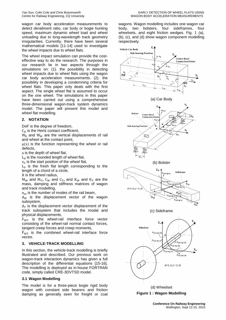
wagons. Wagon modelling includes one wagon car body, two bolsters, four sideframes, four wheelsets, and eight friction wedges. Fig. 1 (a), (b), (c), and (d) show wagon component modelling respectively.
(a) Car Body
(b) Bolster
(c) Sideframe
(d) Wheelset
Figure 1 : Wagon Modelling
Xc
Yc
Zc
x1
Hc
LcrLcf
Side-bearing Position
Centre BowlConnection Points
Vehicle Car Body
VS
kc
kc
Lcp
x2
x3
x4
x5
x6
Xb
YbZb
x6i+1
Hb1
Side-bearing Position
Centre BowlConnection Points
Bolster
x6i+2
x6i+3
x6i+4
x6i+5
x6i+6
Hb2
2Bss
2Lss
Hbw
x12i+6j+1
Sideframe
XSf
YSf
ZSf
Hsfb
Hsfa
x12i+6j+2
x12i+6j+3
x12i+6j+4
x12i+6j+5
x12i+6j+6
(i=1, 2; j = 1, 2)
Xw
YwZw
Wheelset
(i=1, 2; j = 1, 2)
x12i+6j+25
x12i+6j+26
x12i+6j+27
x12i+6j+28
x12i+6j+29
x12i+6j+30
Yan Sun, Colin Cole and Chris Bosomworth EARLY DETECTION OF WHEEL FLATS USING Centre for Railway Engineering, CQ University WAGON BODY ACCELERATION MEASUREMENTS
Conference On Railway Engineering Wellington, Sept 12-15, 2010
All components are modelled as rigid bodies with six degrees of freedom (DoF) (lateral, vertical and longitudinal displacements, and roll, pitch and yaw rotations). The wagon car body, as shown in Fig. 1 (a), rests on two bolsters through two centre bowls and four constant-contact side bearings on the bolster, and is longitudinally connected with two couplers, which are represented as springs. Each centre bowl is modelled with four point contacts through spring and friction elements along the longitudinal, lateral and vertical directions. The constant-contact side bearing is simplified as spring elements in the vertical direction. The bolster as shown in Fig. 1 (b) is supported by the suspension. The sideframe as shown in Fig. 1 (c) is an intermediate structure that provides seating for the suspension and connects to the wheelsets Fig. 1 (d) through steel-steel contacts that are represented as springs with large stiffness. Two kinds of bogie rotations are also taken into account – yaw and lozenge rotations. Nonlinear connection characteristics such as vertical lift-off and lateral and longitudinal impacts between sideframe and wheelset, sideframe and bolster, and bolster and wagon car body are fully considered.
In Fig. 1, represents the DoF, and its subscript indicates the number of DoF. A total of 66 DoF are used to describe the movements of all wagon components. For the wagon car body, the centre bowl connection is considered as a four point lift-off, modelled as a steel-steel contact between car body and bolster along X, Y and Z directions. Side bearings are also included as a lift-off connection as shown in Fig. 1 (a) and (b). The constant-damping friction wedges are taken into account in the modelling but are not shown in Fig. 1(b) and (c) [17-18].
(a) (b)
(c)
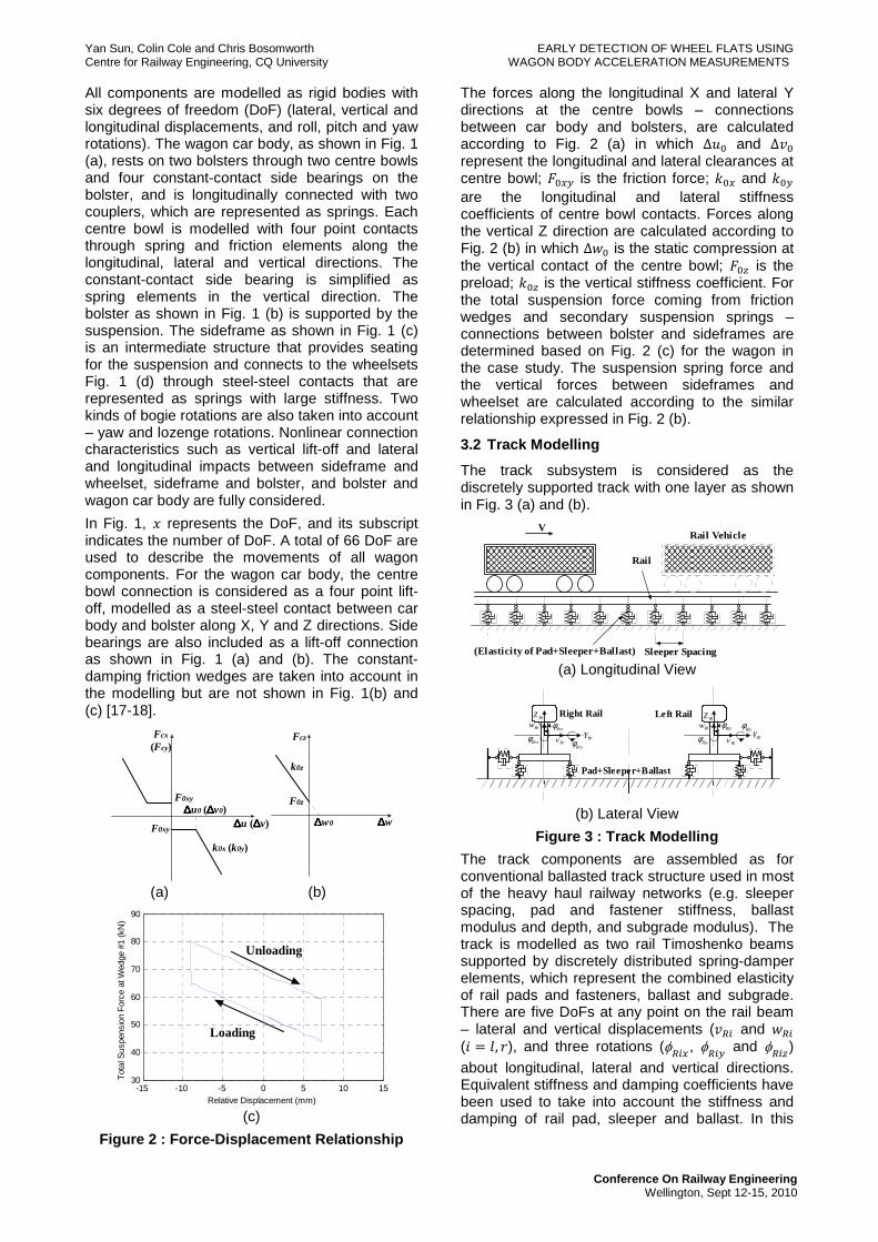
Figure 2 : Force-Displacement Relationship
The forces along the longitudinal X and lateral Y directions at the centre bowls – connections between car body and bolsters, are calculated according to Fig. 2 (a) in which ∆�� and ∆�� represent the longitudinal and lateral clearances at centre bowl; ���� is the friction force; ��� and ��� are the longitudinal and lateral stiffness coefficients of centre bowl contacts. Forces along the vertical Z direction are calculated according to Fig. 2 (b) in which ∆ � is the static compression at the vertical contact of the centre bowl; ��! is the preload; ��! is the vertical stiffness coefficient. For the total suspension force coming from friction wedges and secondary suspension springs – connections between bolster and sideframes are determined based on Fig. 2 (c) for the wagon in the case study. The suspension spring force and the vertical forces between sideframes and wheelset are calculated according to the similar relationship expressed in Fig. 2 (b).
3.2 Track Modelling
The track subsystem is considered as the discretely supported track with one layer as shown in Fig. 3 (a) and (b).
(a) Longitudinal View
(b) Lateral View
Figure 3 : Track Modelling
The track components are assembled as for conventional ballasted track structure used in most of the heavy haul railway networks (e.g. sleeper spacing, pad and fastener stiffness, ballast modulus and depth, and subgrade modulus). The track is modelled as two rail Timoshenko beams supported by discretely distributed spring-damper elements, which represent the combined elasticity of rail pads and fasteners, ballast and subgrade. There are five DoFs at any point on the rail beam – lateral and vertical displacements (�"# and "# ($ % &, (), and three rotations (φ
"#�, φ
"#� and φ
"#!)
about longitudinal, lateral and vertical directions. Equivalent stiffness and damping coefficients have been used to take into account the stiffness and damping of rail pad, sleeper and ballast. In this
∆∆∆∆u (∆∆∆∆v)
Fcx
(Fcy)
∆∆∆∆u0 (∆∆∆∆v0)
k0x (k0y)
∆∆∆∆w
Fcz
k0z
F0z
∆∆∆∆w0F0xy
F0xy
-15 -10 -5 0 5 10 1530
40
50
60
70
80
90
Tot
al S
uspe
nsio
n F
orce
at W
edge
#1
(kN
)
Relative Displacement (mm)
Unloading
Loading
V
(Elasticity of Pad+Sleeper+Ballast)
Rail
Sleeper Spacing
Rail Vehicle
Left RailRight RailRlZ
RlYRlw
Rlv
Rlzφ
Rlxφ
Rrzφ
RrxφRly
φRrw
Rrv
RrZ
RrY
Pad+Sleeper+Ballast
Rryφ
Yan Sun, Colin Cole and Chris Bosomworth EARLY DETECTION OF WHEEL FLATS USING Centre for Railway Engineering, CQ University WAGON BODY ACCELERATION MEASUREMENTS
Conference On Railway Engineering Wellington, Sept 12-15, 2010
track model, the effect of sleeper and ballast masses has not been considered.
For simplicity, the dynamic equilibrium equations of the rail beam have been expanded using a Fourier series in the longitudinal (X) direction by assigning an equal number of terms (n�, also known as the number of modes of the rail beam) for both the linear displacements and the angular rotations.
3.3 Wheel-Rail Interface Modelling
For the wheel-rail interface, the normal force due to wheel-rail rolling contact is determined using Hertz static contact theory. The creep forces and the creep moments are defined using Kalker’s linear creep theory. The comprehensive model includes the vertical and lateral velocities of the rail in the definition of the creepages in the lateral and spin directions. As Kalker’s linear theory best defines the creep forces for very small creepages only, Johnson-Vermeulen’s approach is used to further modify the creep forces. In this paper, the normal contact force F��) is determined using Hertz contact theory and can be expressed in following equation:
[ ]
<µ−−>µ−−µ−−=0)x(wwif0
0)x(wwif)x(wwCF
wR
wR2/3
wRHWTn
(1)
3.4 Wheel Flat Modelling
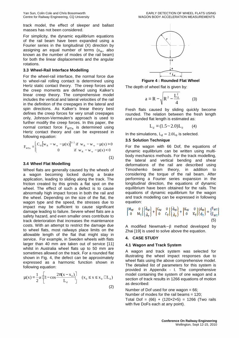
Wheel flats are generally caused by the wheels of a wagon becoming locked during a brake application, leading to sliding along the track. The friction created by this grinds a flat spot on the wheel. The effect of such a defect is to cause abnormally high impact forces in both the rail and the wheel. Depending on the size of the flat, the wagon type and the speed, the stresses due to impact may be sufficient to cause significant damage leading to failure. Severe wheel flats are a safety hazard, and even smaller ones contribute to track deterioration that increases the maintenance costs. With an attempt to restrict the damage due to wheel flats, most railways place limits on the allowable length of the flat that might stay in service. For example, in Sweden wheels with flats larger than 40 mm are taken out of service [11] whilst in Australia wheel flats up to 50 mm are sometimes allowed on the track. For a rounded flat shown in Fig. 4, the defect can be approximately expressed as a harmonic function shown in following equation:
)Lxxx(L
)xx(2cos1a
2
1)x( d00
d
0 +≤≤
−π−⋅=µ
(2)
Figure 4 : Rounded Flat Wheel
The depth of wheel flat is given by:
4
LRRa
202 −−= (3)
Fresh flats caused by sliding quickly become rounded. The relation between the fresh length and rounded flat length is estimated as:
0d L)0.2~5.1(L = (4)
In the simulations, L� % 2.0L� is selected.
3.5 Solution Technique
For the wagon with 66 Dof, the equations of dynamic equilibrium can be written using multi-body mechanics methods. For the track modelling, the lateral and vertical bending and shear deformations of the rail are described using Timoshenko beam theory, in addition to considering the torque of the rail beam. After performing a Fourier series expansion in the longitudinal direction, the equations of dynamic equilibrium have been obtained for the rails. The equations of dynamic equilibrium for the wagon and track modelling can be expressed in following equation:
(5)
A modified Newmark-β method developed by Zhai [19] is used to solve above the equation.
4. CASE STUDY
4.1 Wagon and Track System
A wagon and track system was selected for illustrating the wheel impact responses due to wheel flats using the above comprehensive model. The detailed list of parameters for this system is provided in Appendix - I. The comprehensive model containing the system of one wagon and a section of track results in 1266 equations of motion as described:
Number of Dof used for one wagon = 66; Number of modes for the rail beams = 120; Total Dof = (66) + (120×2×5) = 1266 (Two rails with five DoFs each at any point).
r
a
a
Ld

Yan Sun, Colin Cole and Chris Bosomworth EARLY DETECTION OF WHEEL FLATS USING Centre for Railway Engineering, CQ University WAGON BODY ACCELERATION MEASUREMENTS
Conference On Railway Engineering Wellington, Sept 12-15, 2010
4.2 Simulation Scheme On one wheel, a single wheel flat is assumed and modelled using Eqs. (3) and (4). The simulations were conducted as follows:
• Based on Eq. (3) and (4), the relationship between the wheel flat length and width at the wheel diameter of 850mm was plotted in Fig. 5. The simulations were firstly carried out using the wheel flat sizes shown in Fig. 5 with the right wheel on the first wheelset only having a flat and the wagon with speed of 80 km/h.
Figure 5 : Wheel Flat Sizes
• The simulations were then carried out with the two wheels on the first wheelset having the same flat, with a wagon speed of 80 km/h. The wagon speeds of 60 and 70 km/h were also used along with two wheel flat sizes to examine the effect of various speed-flat combinations.
The above simulations were all conducted with an irregularity spectrum Class 5 track condition. The track top profile irregularities of the track section are shown in Fig. 6.
Figure 6 : Track top profile irregularities
5. DATA PROCESSING
The simulation results – the wheel-rail impact factor (impact force divided by the static wheel load) and the accelerations at the wagon car body front and rear locations above the two bogies were presented to illustrate the data processing.
5.1 Raw Data
The wheel-rail impact factors on the right and left wheels of the first wheelset, with the right wheel having a flat with the length of 50mm, and a wagon speed of 80 km/h, was shown in the below upper and middle plots in Fig. 7. The corresponding FFT magnitude for the impact factor on the right wheel was shown in the bottom plot. It
could be seen that the main frequencies of wheel impact were about 76 Hz for P2 force and 125 Hz for P1 force.
Figure 7 : Wheel load and Its FFT
The vertical acceleration of wagon car body at the front was shown in the upper plot of Fig. 8. The corresponding FFT magnitude was also shown in the lower plot.
Figure 8 : Car Body Acceleration and Its FFT
It could be seen that the main frequencies of car body acceleration include two values. One was very low and about 2 Hz, which came from the vertical natural frequency of bogie suspension system. The other was very high and about 370 Hz, which might be contributed from the vertical friction among the wagon components such as car body and centre bowls on bolsters. From the upper plot in Fig. 8, we could not obtain any useful information.
5.2 Filter Design
In order to draw useful information of wheel impact from the car body accelerations, data filtering of the car body accelerations should be conducted to eliminate the very low (e.g. 2 Hz) and very high (e.g. 370 Hz) frequency components. A filter was designed as shown below Fig. 9. The band pass frequency is between 10 Hz and 200 Hz.

Yan Sun, Colin Cole and Chris Bosomworth EARLY DETECTION OF WHEEL FLATS USING Centre for Railway Engineering, CQ University WAGON BODY ACCELERATION MEASUREMENTS
Conference On Railway Engineering Wellington, Sept 12-15, 2010
Figure 9 : Band-pass Filter
5.3 Filtered Data
The filtered data – the car body accelerations at the front (upper plot) and the back (middle plot) and the right wheel-rail impact factor (bottom plot) were shown in Fig. 10.
Figure 10 : Filtered Data
From Fig. 10, after the very high frequency component was filtered out, the wheel-rail impact factors were in the range of 0.6 ~ 1.5 (the bottom plot in Fig. 10). At the instances of about 0.44s, 0.56s and 0.68s, the right wheel periodically impacted on the rail due to the flat. It could be seen that the accelerations at the front and the back on the car body (the upper and middle plots in Fig. 10) followed the impact pattern, and acceleration impact values measured corresponded. However, the amplitudes of acceleration impacts were not consistent due to the effect of the track irregularity (shown in Fig. 6) and the wagon component friction characteristics including wedge friction (shown in Fig. 2 (c)).
6. Simulation Results
6.1 Single Wheel Flat
In order to detect the early stages of a wheel flat, the simulations had been conducted for a single flat on the right wheel of the first wheelset with the lengths of 10mm to 70mm respectively at the wagon speed of 80 km/h. Fig. 11 (a) ~ (e) showed the accelerations at the car body front and back points, and the right wheel-rail impact factors after filtering. Note that in all cases the wagon body
accelerations is presented for both the front (upper plot) and rear (second plot) of the wagon. The reasoning is that any practical wagon health device will be mounted at just one location, in most cases at one end of the wagon. In these plots, the acceleration readings from the back of the wagon combined with analysis of wheel flats on the leading bogie indicate the worst case for comparison.
(a) Wheel flat = 10mm
(b) Wheel flat = 20mm
(c) Wheel flat = 30mm
Yan Sun, Colin Cole and Chris Bosomworth EARLY DETECTION OF WHEEL FLATS USING Centre for Railway Engineering, CQ University WAGON BODY ACCELERATION MEASUREMENTS
Conference On Railway Engineering Wellington, Sept 12-15, 2010
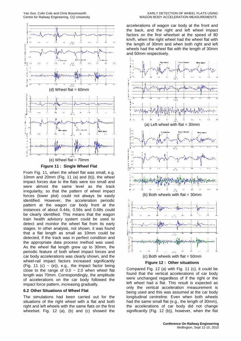
(d) Wheel flat = 60mm
(e) Wheel flat = 70mm
Figure 11 : Single Wheel Flat
From Fig. 11, when the wheel flat was small, e.g. 10mm and 20mm (Fig. 11 (a) and (b)), the wheel impact forces due to the flats were too small and were almost the same level as the track irregularity, so that the pattern of wheel impact forces (lower plot) could not always be easily identified. However, the acceleration periodic pattern at the wagon car body front at the instances of about 0.44s, 0.56s and 0.68s could be clearly identified. This means that the wagon train health advisory system could be used to detect and monitor the wheel flat from its early stages. In other analysis, not shown, it was found that a flat length as small as 10mm could be detected, if the track was in perfect condition and the appropriate data process method was used. As the wheel flat length grew up to 30mm, the periodic feature of both wheel impact forces and car body accelerations was clearly shown, and the wheel-rail impact factors increased significantly (Fig. 11 (c) ~ (e)), e.g., the impact factor being close to the range of 0.0 ~ 2.0 when wheel flat length was 70mm. Correspondingly, the amplitude of accelerations on the car body followed the impact force pattern, increasing gradually.
6.2 Other Situations of Wheel Flat
The simulations had been carried out for the situations of the right wheel with a flat and both right and left wheels with the same flats on the first wheelset. Fig. 12 (a), (b) and (c) showed the
accelerations of wagon car body at the front and the back, and the right and left wheel impact factors on the first wheelset at the speed of 80 km/h, when the right wheel had the wheel flat with the length of 30mm and when both right and left wheels had the wheel flat with the length of 30mm and 50mm respectively.
(a) Left wheel with flat = 30mm
(b) Both wheels with flat = 30mm
(c) Both wheels with flat = 50mm
Figure 12 : Other situations
Compared Fig. 12 (a) with Fig. 11 (c), it could be found that the vertical accelerations of car body were unchanged regardless of if the right or the left wheel had a flat. This result is expected as only the vertical acceleration measurement is being used and this was assumed at the car body longitudinal centreline. Even when both wheels had the same small flat (e.g., the length of 30mm), the accelerations of car body did not change significantly (Fig. 12 (b)), however, when the flat
Yan Sun, Colin Cole and Chris Bosomworth EARLY DETECTION OF WHEEL FLATS USING Centre for Railway Engineering, CQ University WAGON BODY ACCELERATION MEASUREMENTS
Conference On Railway Engineering Wellington, Sept 12-15, 2010
length increased (e.g., 50mm), both accelerations of the car body and the wheel impact force did change significantly (Fig. 12 (c)).
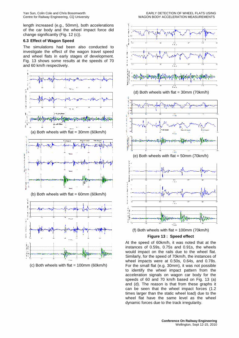
6.3 Effect of Wagon Speed
The simulations had been also conducted to investigate the effect of the wagon travel speed and wheel flats in early stages of development. Fig. 13 shows some results at the speeds of 70 and 60 km/h respectively.
(a) Both wheels with flat = 30mm (60km/h)
(b) Both wheels with flat = 60mm (60km/h)
(c) Both wheels with flat = 100mm (60km/h)
(d) Both wheels with flat = 30mm (70km/h)
(e) Both wheels with flat = 50mm (70km/h)
(f) Both wheels with flat = 100mm (70km/h)
Figure 13 : Speed effect
At the speed of 60km/h, it was noted that at the instances of 0.59s, 0.75s and 0.91s, the wheels would impact on the rails due to the wheel flat. Similarly, for the speed of 70km/h, the instances of wheel impacts were at 0.50s, 0.64s, and 0.78s. For the small flat (e.g. 30mm), it was not possible to identify the wheel impact pattern from the acceleration signals on wagon car body for the speeds of 60 and 70 km/h based on Fig. 13 (a) and (d). The reason is that from these graphs it can be seen that the wheel impact forces (1.2 times larger than the static wheel load) due to the wheel flat have the same level as the wheel dynamic forces due to the track irregularity.

Yan Sun, Colin Cole and Chris Bosomworth EARLY DETECTION OF WHEEL FLATS USING Centre for Railway Engineering, CQ University WAGON BODY ACCELERATION MEASUREMENTS
Conference On Railway Engineering Wellington, Sept 12-15, 2010
However, as the wheel flat increased, the wheel impacts and corresponding wagon car body acceleration impacts could be identified at the speed of 60 km/h for the wheel flat with 60mm (Fig. 13 (b)) and at the speed of 70km/h for the wheel flat with 50mm (Fig. 13 (e)). Fig. 13 (c) and (f) showed the wheel impacts and the wagon car body acceleration impacts at the speeds of 60 and 70 km/h for the wheel flat with 100mm, which clearly showed the periodic patterns.
7. CONCLUSION
A comprehensive wagon and track model has been used to explore the possibility of wheel flat early detection just using the measurement of wagon car body accelerations. The acceleration signals of wagon car body included high frequency components due to the friction between wagon components and low frequency components due to suspension dynamics characteristics. Therefore, the signal processing must be carried out to design suitable data analysis methods. It was found that with appropriate band pass filtering wheel flats could be detected.
The simulations show that the acceleration impact due to wheel flat length as small as 10 or 20mm in the case study can be detected using the acceleration signals of wagon car body provided the wagon was travelling at sufficient speed, (e.g. ~80kph). The case study showed that the wheel flats larger than 30mm were clearly detected form both acceleration signals of the wagon car body. The wheel flat with 30mm should be much less than the alarm wheel flat (e.g., 40mm [11]). The further simulations showed that the periodic pattern of car body acceleration due to wheel flat would be affected by the wagon travel speed and the wheel flat sizes.
REFERENCE
[1] J Jergéus, C Odenmarck, R Lundén, P Sotkovszki, B Karlsson, P Gullers, 1999. Full-scale railway wheel flat experiments. Proceedings of the Institution of Mechanical Engineers, Part F: Journal of Rail and Rapid Transit, Vol. 213, No. 1, pp. 1-13
[2] Masanobu Nankyo, Tadashi Ishihara and Hikaru Inooka, 2006. Feedback Control of Braking Deceleration on Railway Vehicle. Journal of Dynamic Systems, Measurement, and Control, Vol. 128, No. 2, pp. 244-250.
[3] Kawaguchi, K., 2006. Development of WSP system for freight trains. Railway Technology Avalanche, No. 12, July 31, pp. 7
[4] A Bracciali and G Cascini, 1997. Detection of corrugation and wheelflats of railway wheels using energy and cepstrum analysis of rail acceleration. Proceedings of the Institution of Mechanical Engineers, Part F: Journal of Rail and Rapid Transit. Vol. 211, No. 2, pp. 109-116.
[5] D. Barke and W. K. Chiu, 2005. Structural Health Monitoring in the Railway Industry: A Review. Structural Health Monitoring, Vol. 4, No. 1, pp. 81-93.
[6] Karoumi, R., Wiberg, J. and Liljencrantz, A., 2005.Monitoring traffic loads and dynamic effects using an instrumented railway bridge. Engineering Structures, Vol. 27, pp. 1813-1819.
[7] Gary W., 1998. Derailment prevention: early detection is the key, Railway Age, Feb, 1998.
[8] http://www.railinnovation.com.au/innovation/technologies/healthcard.html
[9] F Xia, C Cole and P Wolfs, 2007. An inverse railway wagon model and its applications. Vehicle System Dynamics, Vol. 45, No. 6, pp. 583-605.
[10] F Xia, C Cole and P Wolfs, 2008. Wheel Rail Contact Forces Prediction and Validation with Field Tests. Conference on Railway Engineering, Perth, Australia, 7-10 September 2008, pp. 73-82.
[11] M. Fermér and J.C.O. Nielsen, Vertical interaction between train and track with soft and stiff rail pads—full-scale experiments and theory. Proceedings of the Institution of Mechanical Engineers. Part F—Journal of Rail and Rapid Transit. 209 (1995), pp. 39–47.
[12] A. Johansson and J.C.O. Nielsen, Out-of-round railway wheels—wheel-rail contact forces and track response from full-scale measurements and numerical simulations. Proceedings of the Institution of Mechanical Engineers. Part F—Journal of Rail and Rapid Transit 217 (2003), pp. 135–146.
[13] Dukkipati R.V. and Dong R., 1999. Impact Loads due to Wheel Flats and Shells. Vehicle System Dynamics, Vol. 31, No. 1, pp. 1-22(22)
[14] Wu, T.X. and Thompson, D.J., 2002. A hybrid model for the noise generation due to railway wheel flats. Journal of Sound and Vibration, 251, (1), pp. 115-139.
[15] Sun, Y.Q. and Cole, C., 2007. Wagon-Track Modelling for Simulation of Three-Piece Bogie Suspension Dynamics. Proc. Instn Mech. Engrs., Vol. 221, Part C, 905-917.
[16] Sun, Y.Q., Dhanasekar, M., 2002. A dynamic model for the vertical interaction of the rail track and wagon system. International Journal of Solids and Structures, Vol. 39, 1337-1359.
[17] Sun, Y.Q. and Cole, C., 2007. Comprehensive wagon-Track Modelling for Simulation of Three-Piece Bogie Suspension Dynamics. Proc. Instn Mech. Engrs., Vol. 221, Part C, 905-917.
[18] Sun, Y.Q. and Cole, C., 2008. Vertical Dynamic Behaviour of Three-Piece Wagon Suspensions with Two Types of Friction

Yan Sun, Colin Cole and Chris Bosomworth EARLY DETECTION OF WHEEL FLATS USING Centre for Railway Engineering, CQ University WAGON BODY ACCELERATION MEASUREMENTS
Conference On Railway Engineering Wellington, Sept 12-15, 2010
Wedge. Journal of Multibody Syst Dyn, Vol. 19, 365-382
[19] Zhai, W., 1997. Vehicle-Track Coupling Dynamics. China Railway Publisher, ISBN 7-113-02458-0 (in Chinese).
Appendix - I All Parameters for a Wagon and
Track System
Parameter Value
Wagon Subsystem Wagon car body mass 61000 kg Mass moment of inertia of wagon car body about X axis
86576 kgm2
Mass moment of inertia of wagon car body about Y axis
647182 kgm2
Mass moment of inertia of wagon car body about Z axis
652982 kgm2
Mass of front bolster 465 kg
Mass of rear bolster 365 kg Mass moment of inertia of front bolster about X axis
175 kgm2
Mass moment of inertia of front bolster about Z axis
176 kgm2
Mass moment of inertia of rear bolster about X axis
137 kgm2
Mass moment of inertia of rear bolster about Z axis
138 kgm2
Mass of sideframe 447.5 kg The mass moment of inertia of sideframe about X axis
100.4 kgm2
The mass moment of inertia of sideframe about Y axis
115.6 kgm2
The mass moment of inertia of sideframe about Z axis
115.6 kgm2
Wheelset mass 1120 kg Mass moment of inertia of wheelset about X, Z axis
420.1 kgm2
Mass moment of inertia of wheelset about Y axis
100.4 kgm2
Stiffness coefficient of secondary suspension along Z axis
2.555×10⁶ N/m
Parallelogram stiffness of bogie 5.15×10⁷ N/m Longitudinal distance from the mass centre of wagon car body to the mass centre of the front and the rear bolsters
5.18 m
Semi lateral distance between the left and the right secondary suspensions in a bogie
0.8001 m
Height between the mass centre of the wagon car body and the bolster
0.8 m
Height between the mass centre of the sideframe and the bottom of secondary suspension
0.1786 m
Height between the mass centre of the wheelset and the sideframe
0.05 m
Semi longitudinal distance between wheelsets in a bogie
0.8375 m
Semi lateral distance between the left and the right primary suspensions
0.8001 m
Wheel diameter 0.85 m Track Subsystem
Rail mass per meter 60 kg/m Rail cross-section area 7.77×10⁻³ m2 Elastic modulus of rail 2.07×10¹¹ N/m2 Shear modulus of rail 8.1×10¹⁰ N/m2 Rail second moment of area about Y axis 2.94×10⁻⁵ m4 Rail second moment of area about Z axis 4.9×10⁻⁶ m4 Timoshenko shear coefficient 0.34 Pad stiffness 450 MN/m Sleeper spacing 0.685 m Height of ballast 0.30 m
Height of subballast 0.15 m Elastic modulus of ballast 130×106 N/m2 Elastic modulus of subballast 200×106 N/m2 Subballast modulus 50×106 N/m2 Density of ballast 2600 kg/m3 Density of subballast 2600 kg/m3
Interface Subsystem Hertz spring constant 0.87×10¹¹N/m3/2